
Digital Twin-Driven Reconfigurable Fixturing Optimization for Trimming Operation of Aircraft Skins


School of Mechanical and Material Engineering, North China University of Technology, Beijing 100144, China
Aerospace 2022, 9(3), 154; https://doi.org/10.3390/aerospace9030154
Submission received: 3 February 2022
/
Revised: 25 February 2022
/
Accepted: 1 March 2022
/
Published: 9 March 2022
(This article belongs to the Section Aeronautics)
Abstract
:The incomplete constraint induced by multipoint reconfigurable fixturing and the inherently weak rigidity of thin shell parts significantly hinder the stability of flexible fixturing systems. In particular, during the trimming operation, the number of effective locators may change with the progressive separation of the desired shape from that of the blank part, which easily produces the cliff effect (instantaneous dramatic reduction) of the system stiffness. As a result, the location layout becomes a main crux in reality. Regarding this issue, the author herein presents a digital twin-based decision-making methodology to generate reconfigurable fixturing schemes through integrating virtual and physical information. Considering the intrinsic features of the trimming process, such as the time-varying propagation of the system stiffness and the coupling effects of multiattribute process parameters, the hidden Markov model was introduced to cope with reconfigurable fixturing optimization. To achieve fast convergence and seek a feasible solution, local information (where low system rigidity occurs) was extracted and shared to guide the optimization process in a front-running simulation. To demonstrate the presented method, trimming experiments were performed on a large-size compliant workpiece held by a reconfigurable fixturing system that was developed independently by our research group. The experimental results indicate that the proposed method could adaptively iterate out the optimal locating schema and process control reference from the virtual fixturing and trimming simulation to guarantee the time-varying stability of the trimming process in the real world. Clearly, the digital twin-based reconfigurable fixturing planning approach generated a high possibility of building a context-specific, closed-loop decision-making paradigm and allowing the reconfigurable fixturing system to behave in a more adaptable and flexible manner.
1. Introduction
Large-size thin shell parts are among the most widely used components in industrial applications such as aircraft skins, vehicle cover panels, rocket outer shells, and ship curved panels. Therefore, they cannot be seen as rigid bodies, as they are inherently compliant and usually have complex curved surfaces. The design of fixturing and holding schemes is a critical task during the operations of machining, welding, handling, assembly, and inspection. Traditionally, single-purpose tooling or dedicated fixtures are employed in real manufacturing scenes, but this is not economical for small-batch production and is likely to cause long lead times. Therefore, flexible tooling solutions such as reconfigurable fixtures (RFs), modular fixtures, and robotized fixtures have attracted increasing attentions [1,2], as they are changeable, reconfigurable, programmable, or reusable to suit the dimension and shape changes of compliant parts.
The fact that compliant sheet metal parts are of low stiffness means that they no longer meet the general assumptions around rigid bodies in terms of positioning and constraints; that is to say, the general “3-2-1” location principle cannot provide sufficient constraints. To this end, the “N-2-1” (N ≥ 3) fixture layout principle was proposed [3] and is widely accepted to characterize the positioning and constraining of thin shell or thin sheet parts [4,5]. Clearly, if the number “N” of locators on the primary datum approaches infinity, the locating fixture becomes the traditional single-purpose rigid mold. However, another important problem should be pointed out: in most process operations, such as assembling, laser scribing, welding, and measuring, the effective locators of the “N-2-1” locating schema remain almost the same from the beginning to the end, while during the trimming operation, the effective locators may change with the cutting separation of the desired shape from the original part [6]. In this case, “N” is no longer a constant but a dynamic time-varying variable, so the author suggested replacing “N” with “X” and called this particular location fashion the “X-2-1” location principle [7].
Besides the aforementioned differences in locating principles, the “N-2-1”or “X-2-1” fixturing schemes with inherent multidimensional or dynamic variables make the decision making of the locator layout (i.e., location and number of locators) especially troublesome. The first difficulty is that there does not always exist an analytical or form-closed expression between the fixture layout and the concerned workpiece deformations under the actions of manufacturing process loads such as assembly loading or machining forces [8]. Therefore, most researchers have formulated optimization models of multipoint fixture layouts to achieve the minimum workpiece deformation and computed the deflection under different fixture layouts by the finite element method (FEM). To further solve optimization formulations, many different types of optimization algorithms have been introduced, such as the genetic algorithm [9,10], particle swarm optimization [11], the bat algorithm [12], the nondominated sorting genetic algorithm [13,14], the cuckoo search algorithm [15], and the grey prediction model [16]. All in all, extensive research has been conducted to optimize the fixture layout of thin shell parts by using probability optimization algorithms coupled with FEM. However, these studies are not directly applicable to the case in which the effective locators dynamically change throughout the trimming operation. From the grand vision of smart manufacturing or Industry 4.0, the epistemology of digital twin-embedded cyber-physical systems (CPSs) would bring out extraordinary smart and reconfigurable capabilities for new-generation intelligent manufacturing [17]. The motivation of the current work was triggered by this insight, and the author intended to explore the reconfiguration planning methodology for trimming operations on large-size thin shell parts held by programmable flexible fixtures.
The remainder of this article is organized as follows. Section 2 reviews related works about reconfigurable manufacturing systems and the digital twin modeling method. Section 3 presents the digital twin-based reconfigurable fixturing method and, in particular, the location layout optimization method. Section 4 discusses the experimental work to verify the developed methods. Section 5 presents a further discussion and avenues for forthcoming work. This article concludes in Section 6.
2. Related Works
2.1. Reconfigurable Manufacturing Systems
As a recommended alternative to dedicated manufacturing systems or flexible manufacturing systems, reconfigurable manufacturing systems (RMSs) are advocated to respond to sudden changes in the market or regulatory requirements using basic process modules (hardware and software) that can be recoupled quickly and reliably [18]. More broadly, besides reconfigurable machine tools, reconfigurable robots, conveyors, tooling and fixtures, and inspection machines are the underlying components and key enablers of RMSs. Over a long period in the past, the core reconfigurable characteristics of RMSs were defined by scalability, convertibility, diagnosability, flexibility, integrability, and modularity [19,20]. The reconfiguration driven by the variants of part families in RMSs is usually divided into levels: machine-level and system-level (processes, machine layouts, and resource scheduling) [21]. The true reconfigurability of RMSs largely depends on the quality of decision making: the macroprocess planning, which determines the best sequence among multiple different processing steps and setups, and the microprocess planning, which determines the best process parameters of each individual operation [22]. Thus, reconfigurable process planning and scheduling become very complex when the manufacturing environment is full of heterogeneous, changeable, and multiscale elements and information. It therefore makes sense that although production systems seem to be designed to be reconfigurable, many manufacturing floor shops still lack positive reconfiguration [23].
More recently, the integration of smart technologies under the concept of Industry 4.0 such as Internet of Things (IoT), big data and analytics, artificial intelligence (AI), cloud computing, and autonomous robots might significantly contribute to the full or high-level reconfigurability and flexibility of manufacturing systems [24,25]. For example, the digital twin-enabled reconfigurable modeling approach presented by Zhang et al. [26] provides the possibility to solve the inconsistency between the traditional reconfigurable solutions and the actual situation due to the lack of actual data and constraints. Aiming at the problem of when to reconstruct the RMS, Liu et al. [27] proposed a digital twin-based reconfiguration time point prediction method. Magnanini et al. [28] presented a novel digital twin-based methodology for tactical and strategical decisions in manufacturing systems. Leng et al. [29] demonstrated a digital twin and manufacturing simulation integrated platform embedded in a CPS. Obviously, although the main concerned issues in industrial production systems do not really change, increasingly complex production environments demand the emerging decision-making paradigm and thinking mindset for tackling the connected issues.
2.2. Digital Twin Modeling Method
Initially, as the presenter of the digital twin concept stated, a digital twin is a digital informational construct that is embedded within the physical system itself and connected with the physical counterpart through the system lifecycle [30]. Nearly since 2017, this attractive metaphor has gained increasing attention. Through embedding a digital twin into the CPS, the acquisition and sharing of information have the potential to identify and eliminate the unpredicted undesirable problems of complex systems and then greatly reduce the waste of physical resources (e.g., time, energy, and material). Consequently, digital twins are increasingly regarded as a core part or an implementation manner of CPSs; that is, their frontiers are increasingly overlapping [31]. Digital twin-embedded CPSs hereby generate a high possibility to reshape the manufacturing processes into a deeply digital and smart paradigm transformation. This requires us to have more interdisciplinary factors than just mechanics, electronics, modeling, and simulation, and informatics in particular should be gathered under the umbrella of cybernetics [32].
However, owing to the intrinsic heterogeneity, concurrency, and sensitivity to the timing of CPSs, twinning the conventional and well-known automation system into a digital twin-embedded CPS is full of challenges [33,34]. Digital twin modeling is difficult to achieve overnight; hereby, this means that the “truth” of digital twins is an evolving process throughout the system lifecycle. Madni et al. [35] divided the maturity of digital twins into four levels: pre-digital twin, digital twin, adaptive digital twin, and intelligent digital twin. Currently, there are no specific criteria or universal reference architectures to standardize the digital twinning process. According to the survey, there are mainly four types of representative architectures to offer guidelines and procedures for digital twinning: the generalized layered architecture [36,37], system development lifecycle-based method [38,39], Asset Administration Shell (AAS) framework [40,41], and ISO 23247 digital twin architecture [42]. In fact, whatever they say, the basic configuration of a digital twin system consists of three main parts: a physical entity (asset, process, or system) in real space (physical twin); a digital representation of the physical counterpart in cyberspace; and the cross-space entity to fuse and align the data and information between the physical side and virtual space. Every type of digital replica to mirror the real entity of different granularities can be seen as a twin; thus, it is possible and often also quite advisable for a CPS to match multiple digital twins.
3. Digital Twin-Based Reconfigurable Fixturing Method
3.1. Digital Twin-Driven Paradigm of Reconfigurable Fixturing
The efficiency and effectiveness of reconfiguration planning are some of the most important issues in RMSs [43]. Regarding the reconfigurable fixturing planning for the trimming operation of thin shell parts, its basic task is to transfer the information of the desired model into the location information of the reconfigurable fixture, but the parallel and very different requirements of location accuracy and holding stability throughout the whole process of trimming make the decision making of deterministic locating thorny. For instance, due to the complex interaction dynamics that involves the multipoint location, the low rigidity of thin shell parts, and the ongoing separation of the desired shape, the cliff effect where the stiffness of the fixturing system obviously steps down is very likely to emerge unexpectedly [7]. This emergent behavior would bring out potentially harmful effects or waste expensive large-size thin shell parts owing to out-tolerance, so it needs to be eliminated through reconfigurable fixturing planning. Previous works of modeling and “front-running” simulation analysis provide the necessary foundations for the decision making of reconfiguration planning [6,7,44], but the concept of digital twins tends to integrate the multidisciplinary and multiscale models and bottom-up data of the production site into an actionable continuum. Largely speaking, especially according to our engineering practice in the reconfigurable manufacturing of aircraft skins [2], transforming an RMS into a digital twin-embedded CPS is a natural transition, not a disruptive leap.
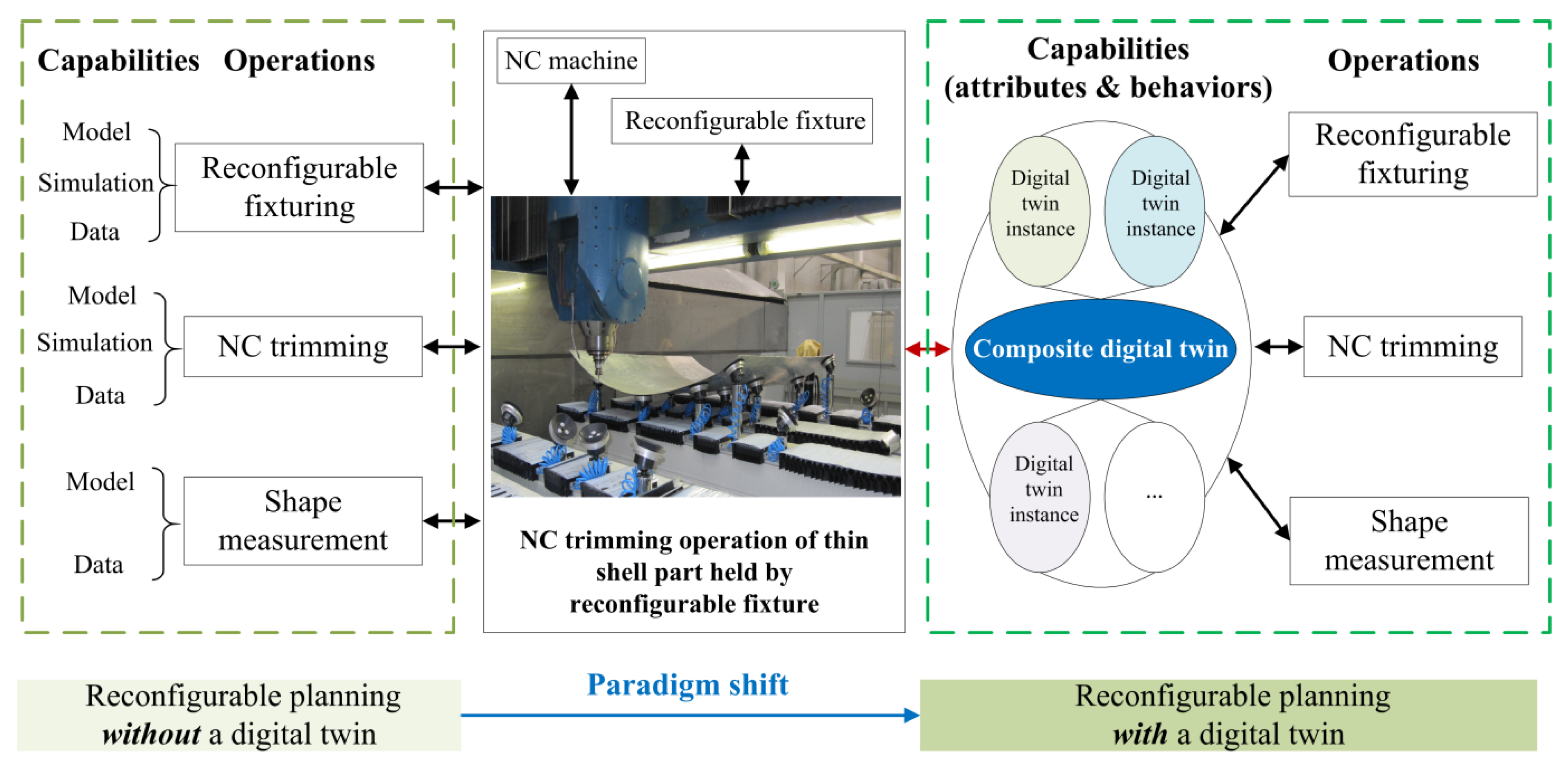
Figure 1 distinguishes what is truly new here and what is not. Without a digital twin, the data and models about an entity are usually scattered, and this leads to broken information flowing across the lifecycle of the entity. Additionally, some information may be repetitive, conflicting, and even missing. Moreover, this may result in decision making of a low efficiency or poor quality. For example, in order to ensure the accurate transmission of the geometric information of the skin part from the stretch forming process to the trimming operation, after the skin part is formed, two to four datum holes need to be punched out as positioning references through the hole-making device on the forming tooling. Relying on the alignment of datum holes and positioning pins on the reconfigurable fixturing tooling, across-space coordination of the part-holding posture between the digital space and reality can be achieved. However, this information transmission of positioning data cannot be obtained directly from the product lifecycle management (PLM) system, and it is only extracted after the stretch forming process. If this information is missed, the information flow of the geometric data would be broken. Additionally, information silos hinder the adoption of advanced techniques such as big data analytics and AI, which require accessing a large amount of information. If there is a digital twin, it would help to cope with the information silo problem. A digital twin serves as a proxy that collects data centrally for every entity and then significantly contributes to the production transparency and near-real-time optimization. The digital twin of an entity is a means of, and the single interface to, accessing its lifecycle information [45]. As said, there may be separate digital twins for a single entity because the context is different and the information is used in different ways.
3.2. Digital Twin-Driven Reconfigurable Fixturing Planning
Following the ISO 23247 digital twin architecture [42], the domain- and entity-based digital twin framework was adopted to describe the digital twinning method of the reconfigurable fixturing planning for the trimming operation of thin shell parts, as shown in Figure 2. Domains refer to a set of functional entities (FEs), which are mainly classified into three categories: the observable physical domain, digital (core) domain, and cross-space domain. Each domain has a logical group of tasks and functions, which are performed by the functional entities or sub-entities of a lower level.
(1) Physical domain. The observable manufacturing domain, alternatively called the physical domain, connects the observable manufacturing elements (OMEs) (e.g., reconfigurable fixture, five-axis numerical control (NC) machine, and blank part) into a real manufacturing system. The available functions of the involved hardware and their embedded software systems belong to the physical domain. Here, the reconfigurable fixturing system was developed independently by our research group, and the moveable and stoppable vacuum end effectors can be accurately controlled in three directions by the computer control system. Meanwhile, the end effectors can swivel up to 45° in any direction; thus, they can adaptively contact and support the free-form workpiece. The working parameters of the developed reconfigurable fixture are listed in Table 1. The physical domain definitely determines the maximum possible capability frontier of the real production system.
(2) Digital domain. The digital domain, or the cyberspace domain, is responsible for the overall operation and management of digital twins (e.g., digital twin of reconfigurable fixturing, digital twin of NC trimming). The digital twin of reconfigurable fixturing hosts core functions such as model-based feature extraction, location allowance judging, part-holding posture design, and reconfigurable layout optimization. The model-based feature extraction is to collect the geometric information of blank and as-designed parts such as the trimming lines and contour edges. The location allowance judging method, part-holding posture determination method, and FEM simulation method were developed in a previous work [7] and are not further covered here. The reconfigurable layout optimization method is introduced in Section 3.3. The simulation and optimization in the digital domain are responsible for generating a layout solution and control compliance for the real process.
(3) Cross-space domain. The cross-space domain is responsible for the absolute data translation and information interactions between the virtual model and real entity: for example, the layout design data and NC program. The recent advances in industrial information and communication technologies such as fieldbuses, Ethernet, and Open Platform Communications (OPC) substantially consolidated the technological foundation of real-time, reliable, and secure transmission of different types of data. The alignment and fusion of simulated data, measured data, and master data of the RF and different semantic information (e.g., system stiffness, layout, and accuracy) enable the physical entities and virtual models to be integrated into a whole system. In this work, to measure the time-varying stiffness of the in-process fixturing system, the dynamic displacements of key reference points (KRPs) were real-time monitored by the eddy current displacement sensors. Through aligning the measured displacements of KRPs with the simulated displacements of the corresponding KRPs, the time-varying stiffness of the in-process fixturing system is clearly controlled within the allowable range as the front-running simulation optimization results predict.
3.3. Reconfigurable Fixturing Optimization Method
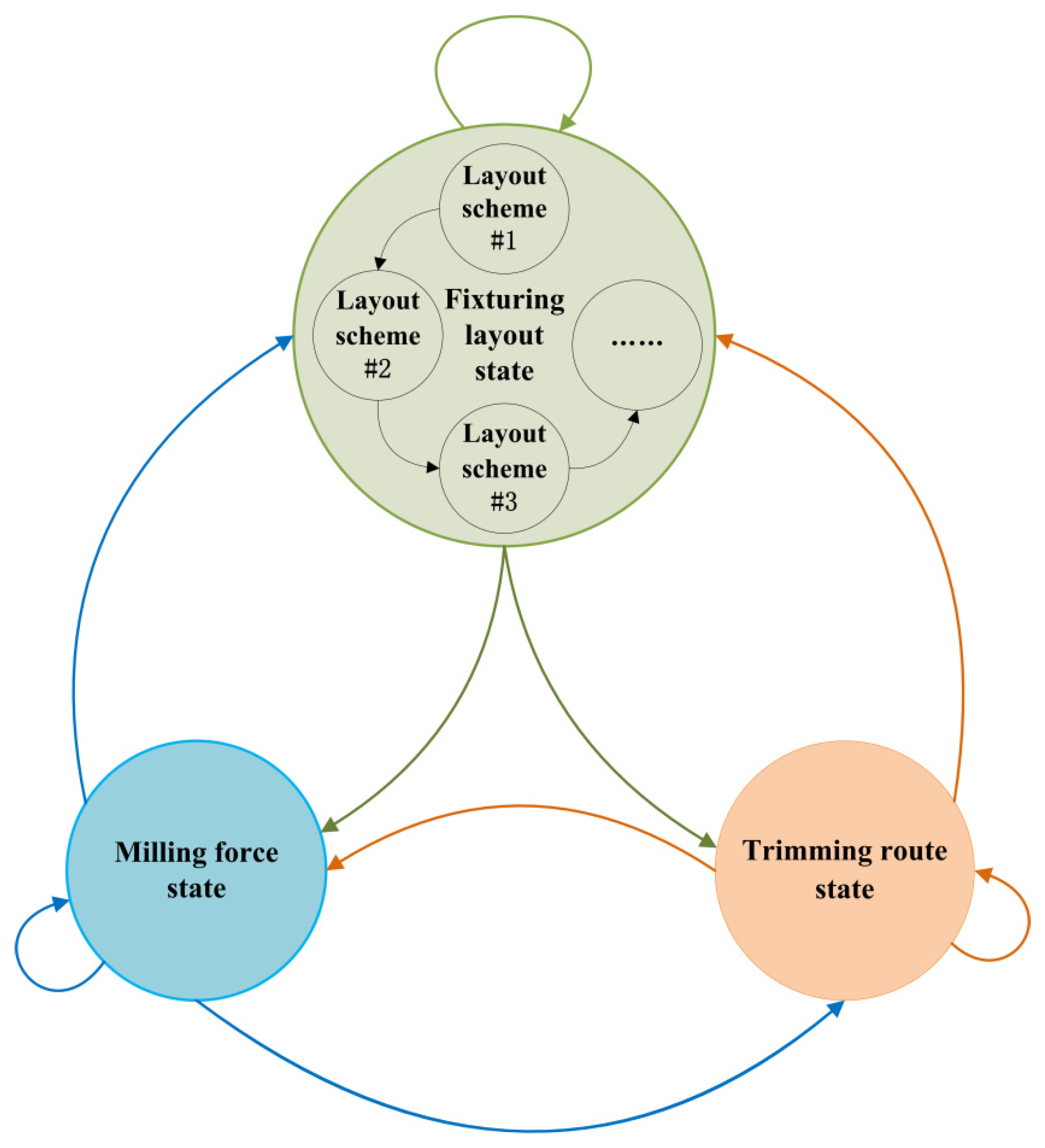
From the foregoing discussion, owing to the progressive separation of the desired shape from that of the blank part throughout the whole trimming process, the interaction dynamics of the whole trimming process is highly time-variably nonlinear and has a complex state space that involves heterogeneous variables such as the location layout, machining forces, and trimming route. Obviously, the stiffness representation of the fixturing system cannot be directly characterized by an analytic method, so the hidden Markov model (HMM) was used to describe the complex coupling effects of heterogeneous variables on the in-process stiffness of the fixturing system (see Figure 3). Further, the FEM simulation model was adopted to simulate the material removal process and estimate the maximum fluctuation amplitude of the dynamic deformations [7]. The FEM method can perform batch simulation calculations of the in-process stiffness of the fixturing system, and according to the simulated results, the HMM further drives the combinational optimization of heterogeneous variables with the conditional probabilities in the allowable state spaces. That is to say, the interaction dynamics model of the whole trimming process is built in the virtual space by the combination of HMM and FEM. The FEM simulation method was developed in a previous work [7] and is not further covered here. Next, the layout optimization method of RFs is introduced.
Given a 3D free-form surface part with the trimming contours, the layout optimization problem of locators can be formulated as
where denotes the position coordinates of the allowable locators. In the array , the first subscript is the number of the movable frame, and the second subscript is the number of the telescopic rods in the same movable frame. To avoid the excessive fluctuation of the fixturing system’s stiffness, as many locators as possible should be arranged according to the size of the thin shell blank workpiece. Once the number of allowable locators is confirmed, the remaining task is to determine their positions. The function “” denotes the FEM simulation process containing the boundary constraints, material removal, solution, and stiffness evaluation of the in-process system. As stated, in order to quantitatively characterize the system stiffness, a certain number of KRPs are defined along the trimming path, and the standard deviation of their normal deflections is viewed as the indicator of the fixturing system’s stiffness. In the constraints, denotes the allowed region on the part surface that can be sucked by the suction cups; and are the minimum intervals of the X-axis and Y-axis, respectively (see Table 1); is the maximum allowable fluctuation value considering the system stability and the contour accuracy.
In the FEM simulation of the trimming process, according to the element life and death technique, the basic principle of material removal is to sequentially “kill” the elements on the trimming paths to simulate the cutting separation process of the desired part. Meanwhile, the milling forces are exerted on the elements that would be “killed” in the next step. The milling forces’ magnitude is modeled by the experimental measurement data [46]. Every time the trimming simulation may result in a very long computation time, this renders the application of large-scale population-dependent global optimization algorithms unfeasible. An insight is the opinion that the reconfigurable layout process is not entirely stochastic, and the optimizing direction of the locator layout reconfiguration should change to the local regions where the KRPs’ normal deflections are serious. Indeed, the probability density function of the locator layout is high-dimensional and unknown. To this end, we introduced the Markov chain Monte Carlo (MCMC) sampling method to generate the new potential samples that depend on a transition probability [47]. The sequence of layout samples explores the state space following a Markov chain mechanism to imitate a target distribution. The differential evolution sequence of the locator layout reconfiguration is formulated by
where the state transition probability denotes the probability array , which is defined according to the Manhattan distance between the locators and KRPs’ position (, ) where the normal deflections are serious; denotes the deformation array [] of numbers of KRPs, which is calculated from the FEM simulation, where the closer the locators to the regions where the normal deflections are serious, the bigger the transition probability adjusting these locators; is the predefined step size to adjust the locators. The transition probability array is now approximated by
where and are the coefficients of the preferred movement direction. Since the movement of one X-axis frame of the RF would cause the collective movement of the rods in the same frame, is defined as 0.2 and is preferred to be 0.8 to prioritize the adjustment of the Y-axis. Further, the adjustment of locators also needs to confirm the status transition direction , which is defined by
Obviously, in the presented Markov chain, given an initial layout and the transition probabilities, the optimized layout could be predicted. In particular, the information extraction of the fixturing system stiffness distribution helps to update the location layout and accelerate the convergence of the iteration process. Once the standard deviation of KRPs’ normal deflections reaches the acceptable range, the differential evolution procedure can stop. To implement the simulation optimization in Abaqus software, a plug-in program was developed to conduct the iterative procedures by using the Python scripting.
4. Experiment
4.1. Process Planning in Digital Space
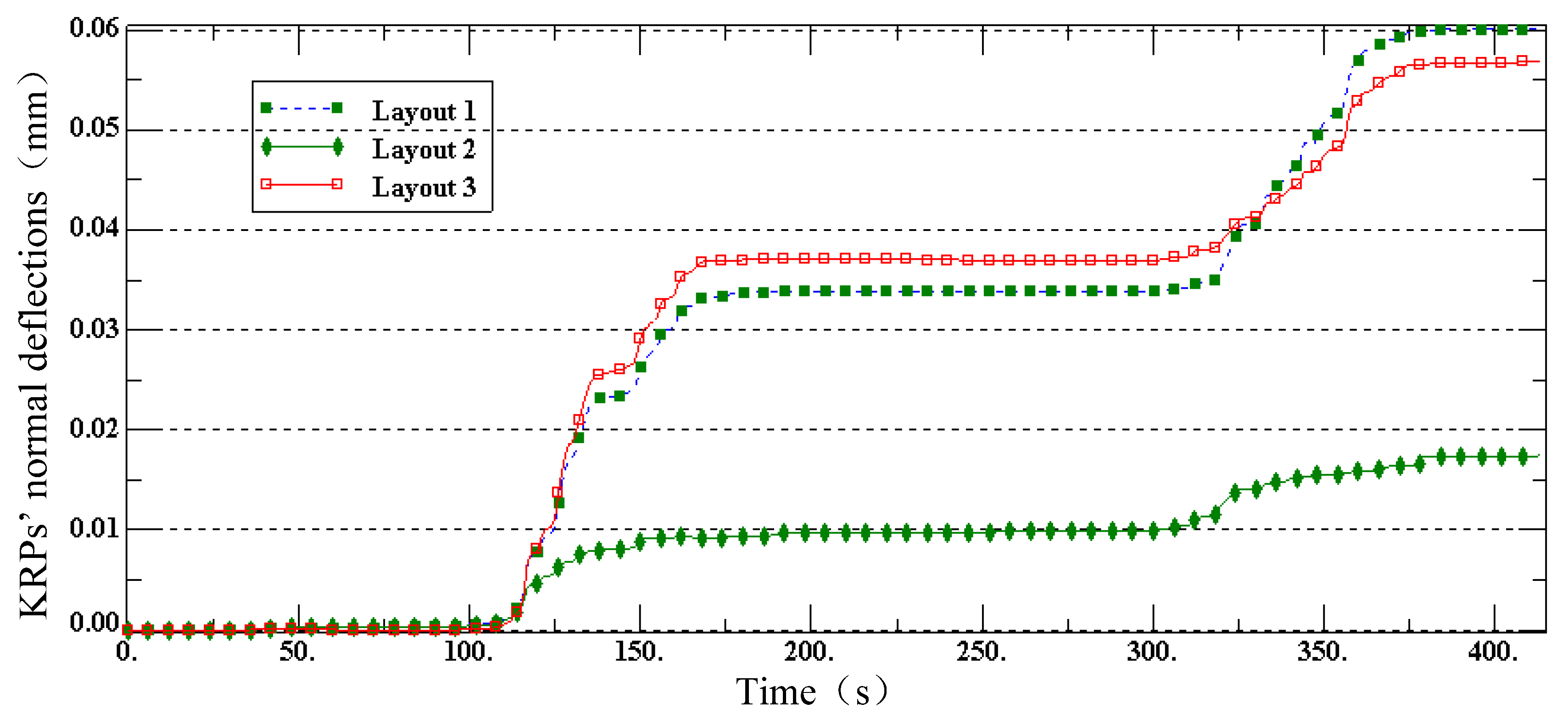
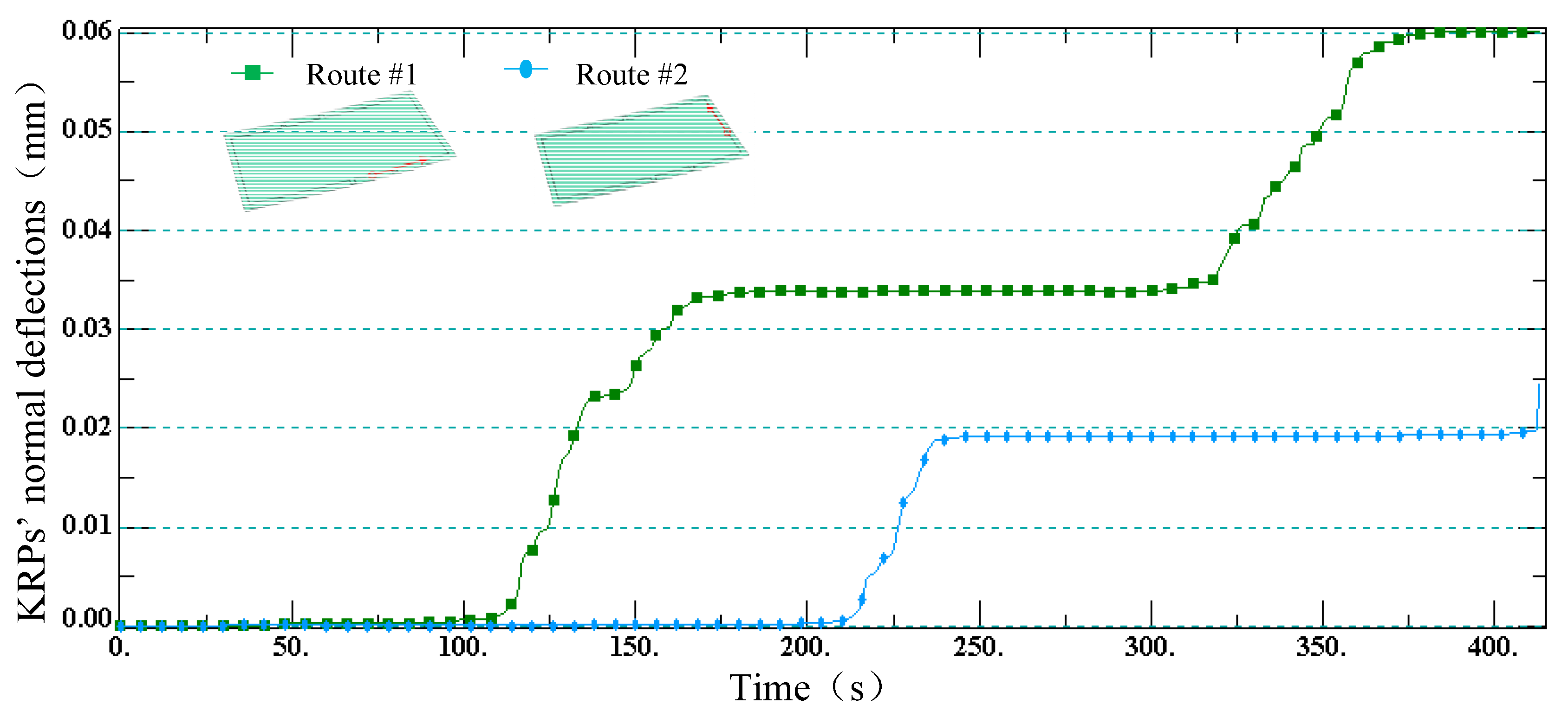
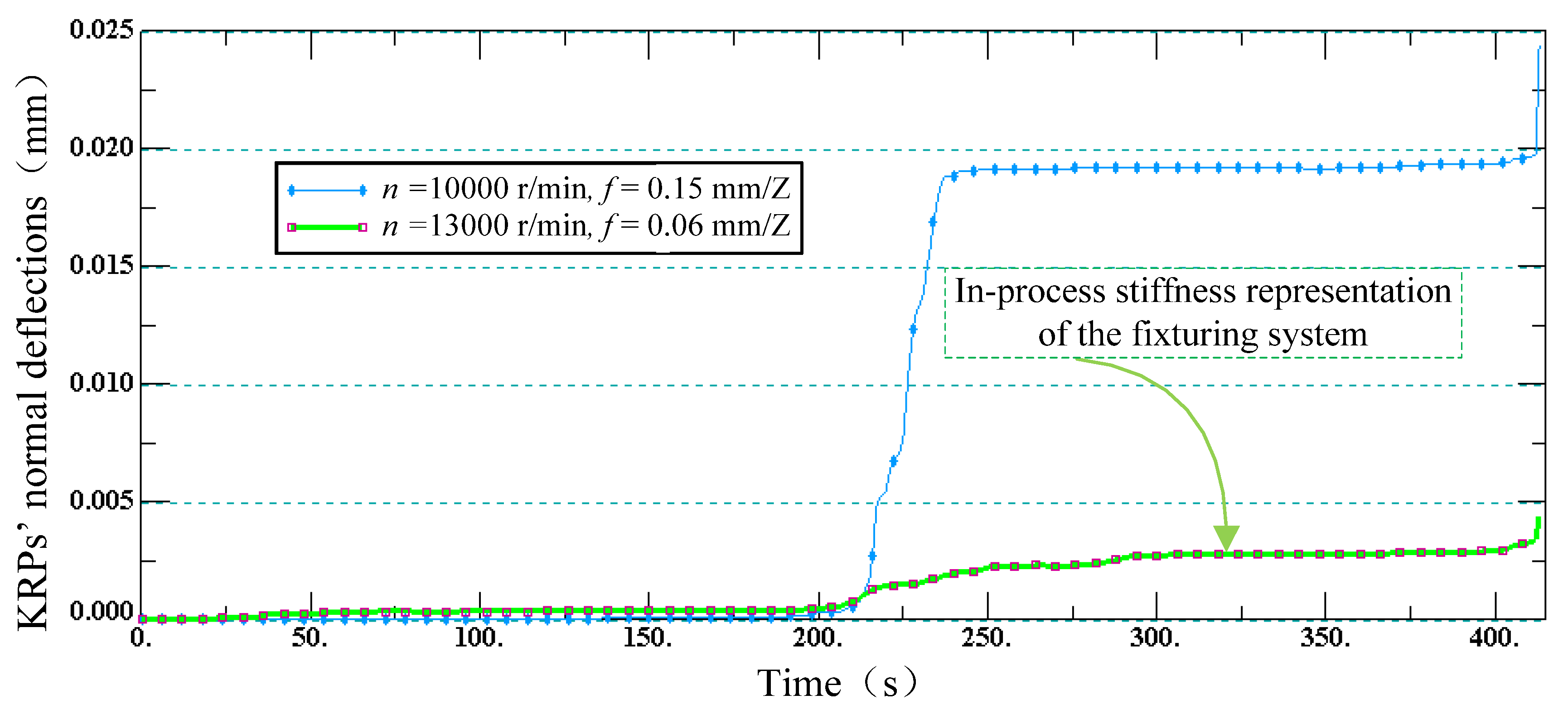
As a proof of concept, an aluminum alloy (2B06) skin part with a thickness of 1.27 mm was selected to be held by the reconfigurable fixturing system, then to be trimmed by the five-axis high-speed milling machine. The milling cutter is a solid carbide endmill with two teeth, an 8 mm diameter, and a 30° helix angle. According to the presented method, in the virtual domain, the time-varying stiffness of the in-process fixturing system was measured by the KRPs’ deformations. Three aspects of process parameters including the location layout, trimming routes, and cutting parameters were considered in the decision-making process with the HMM. Here, the transition probabilities of the milling force state and the trimming route state were equally distributed in the given options. Figure 4, Figure 5 and Figure 6 visually present the evolution sequence of the time-varying stiffness of the in-process fixturing system.
Clearly, after the optimization prediction, it can be seen that the cliff effects of the in-process dynamic stiffness almost disappeared and the standard deviation of KRPs’ normal deflections was less than 0.005 mm (see Figure 6), which was far less than the required limit value of 0.5 mm. The final optimized process scheme is shown in Table 2.
4.2. In-Process Monitoring and Results in Physical Space
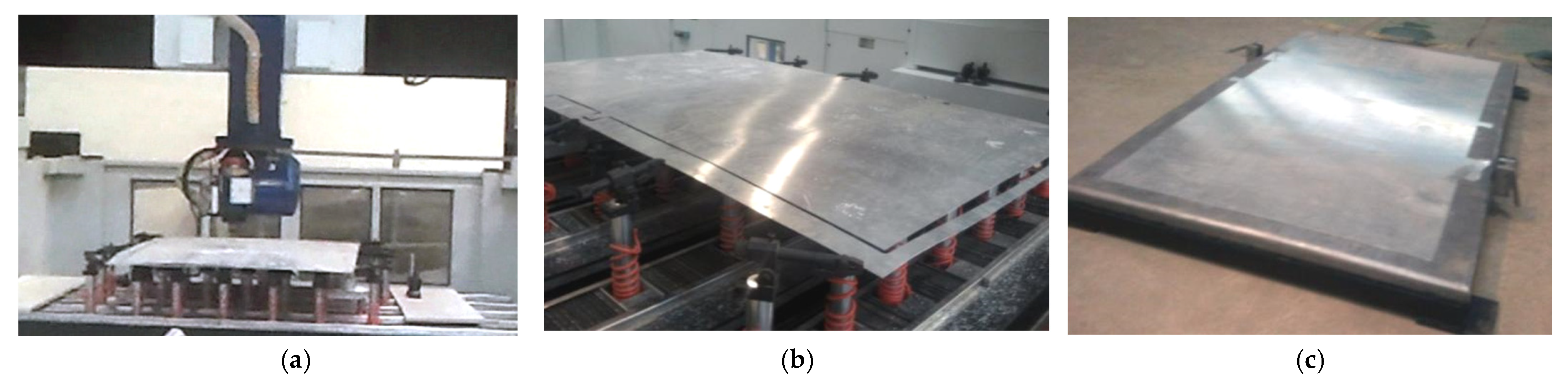
Figure 7a,b show the in-operation trimming process. The real-time displacements of the KRPs were real-time monitored by the eddy current displacement sensors. The measured data of KRPs’ vibration amplitudes in the real process were less than the simulated data of counterparts in the virtual simulation; that is to say, the fixturing system showed good stability during the whole process. After that, the finalized part was placed on the stretching tool, and the trimming accuracy was checked by the datum profile and datum holes, as shown in Figure 7c. The edge dimension error was less than 0.1 mm in the measurement with the filler gauge. This suggests that the optimized process scheme successfully ensured the “first pass“, and the experimental results are very exciting. Undoubtedly, the proposed solution contributed to reducing the blindness and experience dependence of the complex process planning.
5. Discussions
No matter how magnificent the vision of the digital twin metaphor is, its vitality lies in the industrial applications. However, owing to the complexities of twinning the reality with a fully peer-to-peer digital avatar, the digital twin applications in production systems have not progressed enough in recent years [48]. Obviously, as a positive practice of the digital twin concept, a digital twin-driven reconfigurable fixturing optimization method was presented. The contributions, novelty, and limitations of this work are summarized in Table 3. For better future research, the author keeps a more open mind to discuss what this exploration means to the smartness enhancement of RMSs.
Embedding a digital twin into an RMS demonstrates powerful potential to enable the RMS to be both smarter and reconfigurable to unpredictable or complex changes. The bidirectional information fusion brings about more information gains to guide the decision making and produce the closed-loop process control that merges the virtual space and real world. In this work, although the time-varying stiffness of the fixturing system could not be modeled by analytical methods and be controlled by the universal control law, it can be predicted to serve as a reference to the real-time control. This suggestion could be also introduced into the complex product assembly to ensure stability [49] and generate the optimal assembly sequence [50,51]. The tight coupling between the simulation and optimization in cyberspace and the sensory feedback in the physical world opens new opportunities to build system-level reconfigurable and intelligent manufacturing systems with high-dimensional, nonlinear, and heterogeneous features or elements. This demands the digital twin-driven all-round development view of products, processes, and resources, just as illustrated in Figure 1.
The digital twin concept helps to reshape the design development of reconfigurable machines. For a long time, the integrability, modularity, reconfigurability, and other flexible capabilities have been the representative pursuits to develop reconfigurable equipment. In engineering practice, the planning, development, execution, measurement, and analysis are separate and serial, and the same is true for our previous research. Without the high-level information fusion, the adaptability of RMSs to uncertain and complex events cannot be sufficiently shown. The reason may be the lack of sensors, but the underlying reason is the inability to know in advance what decisions should be taken or how to synthesize the measured data. The available information, in-process feedback, changeable modular structures, and embedded intelligence should be seamlessly integrated to bridge the gaps between virtual and physical systems toward the new generation of industry.
6. Conclusions
Industry 4.0 indicates that future manufacturing is becoming smart to autonomously adapt to uncertain and unpredictable changes. The ambition of reconfigurable manufacturing systems and the pursuit of smart manufacturing converge at this point. Embedding a digital twin into a cyber-physical production system generates new opportunities for the decision-making mechanism, optimization, and control of manufacturing processes. On the basis of earlier research, this research endeavored to extend the digital twin concept to an engineering practice, and this tiny progress has contributed to the better reconfigurability and flexibility of a reconfigurable fixturing system.
Specifically, the complex interaction dynamics that involves multipoint holding, the low rigidity of the thin shell part, and the ongoing separation of the desired shape causes the reconfigurable fixturing and trimming process to be full of high complexity and uncertainty. To alleviate this, a digital twin-based reconfigurable fixturing planning framework was presented by combining the simulation optimization method and the online measurement in the real process. The simulation optimization in the virtual space successfully generated a layout recommendation and a reference criterion for the real process control. The unpredicted undesirable problem that the stiffness of the fixturing system dramatically drops down was successfully identified and eliminated. Clearly, the digital twin-based model that characterizes the whole environment could provide a holistic and contextual insight into the complex process, rather than simple abstractions of reality investigated in a highly fragmented fashion. Philosophically, this indicates that industrial modeling and cybernetics are transcending the traditional rigid system into the digital ecosystem.
Funding
This project was supported by the cooperation project between industry and universities approved by the Ministry of Education of China (Grant No. 202002148005), and by the National Key Research and Development Program of China (Grant No. 2021YFE0103800).
Data Availability Statement
All data generated or analyzed during this study are included in this article.
Conflicts of Interest
The author declares no conflict of interest.
Abbreviations
| AI | Artificial intelligence |
| AAS | Asset Administration Shell |
| CPS | Cyber-physical system |
| DT | Digital twin |
| FEM | Finite element method |
| FE | Functional entity |
| HMM | Hidden Markov model |
| ISO | International Organization for Standardization |
| IoT | Internet of Things |
| KRP | Key reference point |
| MCMC | Markov chain Monte Carlo |
| NC | Numerical control |
| OME | Observable manufacturing element |
| OPC | Open Platform Communications |
| PLM | Product lifecycle management |
| RF | Reconfigurable fixture |
| RMS | Reconfigurable manufacturing system |
References
- Shirinzadeh, B. Flexible fixturing for workpiece positioning and constraining. Assem. Autom. 2002, 22, 112–120. [Google Scholar] [CrossRef]
- Jonsson, M.; Ossbahr, G. Aspects of reconfigurable and flexible fixtures. Prod. Eng. 2010, 4, 333–339. [Google Scholar] [CrossRef]
- Cai, Z.Y.; Wang, S.H.; Xu, X.D.; Li, M.Z. Numerical simulation for the multi-point stretch forming process of sheet metal. J. Mater. Proces. Technol. 2009, 209, 396–407. [Google Scholar] [CrossRef]
- Ceglarek, D.; Li, H.F.; Tang, Y. Modeling and Optimization of End Effector Layout for Handling Compliant Sheet Metal Parts. J. Manuf. Sci. Eng. 2001, 123, 473–480. [Google Scholar] [CrossRef] [Green Version]
- Das, A.; Franciosa, P.; Ceglarek, D. Fixture Design Optimisation Considering Production Batch of Compliant Non-Ideal Sheet Metal Parts. Procedia Manuf. 2015, 1, 157–168. [Google Scholar] [CrossRef] [Green Version]
- Hu, F.; Li, D.; Li, X.; Zhu, M. Locating simulation for aircraft skins NC trimming based on flexible holding fixture. Comput. Integr. Manufact. Syst. 2012, 18, 993–998. [Google Scholar] [CrossRef]
- Hu, F. Location Issues of Thin Shell Parts in the Reconfigurable Fixture for Trimming Operation. J. Aerosp. Technol. Manag. 2014, 6, 319–331. [Google Scholar] [CrossRef] [Green Version]
- Rezaei Aderiani, A.; Hallmann, M.; Wärmefjord, K.; Schleich, B.; Söderberg, R.; Wartzack, S. Integrated Tolerance and Fixture Layout Design for Compliant Sheet Metal Assemblies. Appl. Sci. 2021, 11, 1646. [Google Scholar] [CrossRef]
- Ahmad, Z.; Zoppi, M.; Molfino, R. Fixture layout optimization for large metal sheets using genetic algorithm. World Acad. Sci. Eng. Technol. 2013, 79, 1487–1492. [Google Scholar]
- Lu, C.; Zhao, H.W. Fixture layout optimization for deformable sheet metal workpiece. Int. J. Adv. Manuf. Technol. 2015, 78, 85–98. [Google Scholar] [CrossRef]
- Xing, Y.; Wang, Y. Fixture layout design based on two-stage method for sheet metal components. Proc. Inst. Mech. Eng. Part B J. Eng. Manuf. 2013, 227, 162–172. [Google Scholar] [CrossRef]
- Wang, Z.; Yang, Y.; Yang, B.; Kang, Y. Optimal sheet metal fixture locating layout by combining radial basis function neural network and bat algorithm. Adv. Mech. Eng. 2016, 8, 1687814016681905. [Google Scholar] [CrossRef] [Green Version]
- Xing, Y.; Hu, M.; Zeng, H.; Wang, Y. Fixture layout optimisation based on a non-domination sorting social radiation algorithm for auto-body parts. Int. J. Prod. Res. 2014, 53, 3475–3490. [Google Scholar] [CrossRef]
- Yang, Y.; Wang, Z.; Yang, B.; Jing, Z.; Kang, Y. Multiobjective Optimization for Fixture Locating Layout of Sheet Metal Part Using SVR and NSGA-II. Math. Probl. Eng. 2017, 2017, 7076143. [Google Scholar] [CrossRef] [Green Version]
- Yang, B.; Wang, Z.; Yang, Y.; Kang, Y.; Li, X. Optimum fixture locating layout for sheet metal part by integrating kriging with cuckoo search algorithm. Int. J. Adv. Manuf. Technol. 2016, 91, 327–340. [Google Scholar] [CrossRef]
- Yang, B.; Wang, Z.; Yang, Y.; Jing, Z.; Kang, Y. Determination of the Number of Fixture Locating Points for Sheet Metal By Grey Model. MATEC Web Conf. 2017, 95, 07018. [Google Scholar] [CrossRef] [Green Version]
- Morgan, J.; Halton, M.; Qiao, Y.; Breslin, J.G. Industry 4.0 smart reconfigurable manufacturing machines. J. Manuf. Syst. 2021, 59, 481–506. [Google Scholar] [CrossRef]
- Pansare, R.; Yadav, G.; Nagare, M.R. Reconfigurable manufacturing system: A systematic review, meta-analysis and future research directions. J. Eng. Des. Technol. 2021. [Google Scholar] [CrossRef]
- Koren, Y.; Ulsoy, A.G. Vision, principles and impact of reconfigurable manufacturing systems. Powertrain Int. 2002, 5, 14–21. [Google Scholar]
- Koren, Y.; Shpitalni, M. Design of reconfigurable manufacturing systems. J. Manuf. Syst. 2010, 29, 130–141. [Google Scholar] [CrossRef]
- Ameer, M.; Dahane, M. Reconfigurability improvement in Industry 4.0: A hybrid genetic algorithm-based heuristic approach for a co-generation of setup and process plans in a reconfigurable environment. J. Intell. Manuf. 2021, 1–23. [Google Scholar] [CrossRef]
- Khezri, A.; Benderbal, H.H.; Benyoucef, L. Towards a sustainable reconfigurable manufacturing system (SRMS): Multi-objective based approaches for process plan generation problem. Int. J. Prod. Res. 2021, 59, 4533–4558. [Google Scholar] [CrossRef]
- Maganha, I.; Silva, C.; Ferreira, L.M.D. Understanding reconfigurability of manufacturing systems: An empirical analysis. J. Manuf. Syst. 2018, 48, 120–130. [Google Scholar] [CrossRef]
- Singh, A.; Gupta, P.; Asjad, M. Reconfigurable manufacturing system (rms): Accelerate towards industries 4.0. In Proceedings of the International Conference on Sustainable Computing in Science, Technology and Management (SUSCOM), Amity University Rajasthan, Jaipur, India, 26–28 February 2019. [Google Scholar] [CrossRef]
- Rojko, A. Industry 4.0 concept: Background and overview. Int. J. Interact. Mobile Technol. 2017, 11, 77–90. [Google Scholar] [CrossRef] [Green Version]
- Zhang, C.; Xu, W.; Liu, J.; Liu, Z.; Zhou, Z.; Pham, D.T. Digital twin-enabled reconfigurable modeling for smart manufacturing systems. Int. J. Comput. Integr. Manuf. 2019, 34, 709–733. [Google Scholar] [CrossRef]
- Liu, Z.; Wang, T.; Zhou, Y.; Zhao, W.; Zheng, M.; Ke, Z.; Zhao, X. Digital Twin-Based Reconfiguration Time Point Prediction Method for Reconfigurable Manufacturing Systems. J. Phys. Conf. Ser. 2022, 2173, 012058. [Google Scholar] [CrossRef]
- Magnanini, M.C.; Tolio, T.A.M. A model-based Digital Twin to support responsive manufacturing systems. CIRP Ann. 2021, 70, 353–356. [Google Scholar] [CrossRef]
- Leng, B.; Sun, H.; Si, G.; Xia, T.; Wang, H. Digital Twin and Manufacturing Simulation Integrated Platform embedded in cyber-physical system. J. Phys. Conf. Ser. 2021, 1983, 012117. [Google Scholar] [CrossRef]
- Grieves, M.; Vickers, J. Digital twin: Mitigating unpredictable, undesirable emergent behavior in complex systems. In Transdisciplinary Perspectives on Complex Systems; Springer: Cham, Switzerland, 2017; pp. 85–113. [Google Scholar]
- Uhlemann, H.J.; Lehmann, C.; Steinhilper, R. The Digital Twin: Realizing the Cyber-Physical Production System for Industry 4.0. Proc. CIRP 2017, 61, 335–340. [Google Scholar] [CrossRef]
- Hu, F. Mutual information-enhanced digital twin promotes vision-guided robotic grasping. Adv. Eng. Inform. 2022, 52, 101562. [Google Scholar] [CrossRef]
- Derler, P.; Lee, E.A.; Vincentelli, A.S. Modeling cyber–physical systems. Proc. IEEE 2011, 100, 13–28. [Google Scholar] [CrossRef]
- Ribeiro, L.; Bjorkman, M. Transitioning From Standard Automation Solutions to Cyber-Physical Production Systems: An Assessment of Critical Conceptual and Technical Challenges. IEEE Syst. J. 2017, 12, 3816–3827. [Google Scholar] [CrossRef] [Green Version]
- Madni, A.M.; Madni, C.C.; Lucero, S.D. Leveraging digital twin technology in model-based systems engineering. Systems 2019, 7, 7. [Google Scholar] [CrossRef] [Green Version]
- Zhang, X.; Zhu, W. Application framework of digital twin-driven product smart manufacturing system: A case study of aeroengine blade manufacturing. Int. J. Adv. Robot. Syst. 2019, 16, 1729881419880663. [Google Scholar] [CrossRef] [Green Version]
- Tao, F.; Zhang, M.; Liu, Y.; Nee, A.Y.C. Digital twin driven prognostics and health management for complex equipment. CIRP Ann. 2018, 67, 169–172. [Google Scholar] [CrossRef]
- Qamsane, Y.; Moyne, J.; Toothman, M.; Kovalenko, I.; Balta, E.C.; Faris, J.; Tilbury, D.M.; Barton, K. A Methodology to Develop and Implement Digital Twin Solutions for Manufacturing Systems. IEEE Access 2021, 9, 44247–44265. [Google Scholar] [CrossRef]
- Moyne, J.; Qamsane, Y.; Balta, E.C.; Kovalenko, I.; Faris, J.; Barton, K.; Tilbury, D.M. A Requirements Driven Digital Twin Framework: Specification and Opportunities. IEEE Access 2020, 8, 107781–107801. [Google Scholar] [CrossRef]
- Cavalieri, S.; Salafia, M.G. A model for predictive maintenance based on asset administration shell. Sensors 2020, 20, 6028. [Google Scholar] [CrossRef]
- Jacoby, M.; Jovicic, B.; Stojanovic, L.; Stojanović, N. An Approach for Realizing Hybrid Digital Twins Using Asset Administration Shells and Apache Stream Pipes. Information 2021, 12, 217. [Google Scholar] [CrossRef]
- Shao, G. Use Case Scenarios for Digital Twin Implementation Based on ISO 23247; National Institute of Standards: Gaithersburg, MD, USA, 2021. [CrossRef]
- Kurniadi, K.A.; Lee, S.; Ryu, K. Digital Twin Approach for Solving Reconfiguration Planning Problems in RMS. In Proceedings of the IFIP International Conference on Advances in Production Management Systems, Seoul, Korea, 26–30 August 2018; Springer: Cham, Switzerland, 2018; pp. 327–334. [Google Scholar] [CrossRef]
- Hu, F.; Li, D.; Li, X.; Zhu, M. Process planning of aircraft skins NC trimming based on reconfigurable fixture. J. Beijing Univ. Aeronaut. Astronaut. 2012, 38, 675–680. [Google Scholar] [CrossRef]
- Industrial Internet Consortium, Digital Twins for Industrial Application, an Industrial Internet Consortium White Paper. Available online: https://www.iiconsortium.org/pdf/IIC_Digital_Twins_Industrial_Apps_White_Paper_2020-02-18.pdf (accessed on 25 February 2021).
- Hu, F.; Li, D. Modelling and Simulation of Milling Forces Using an Arbitrary Lagrangian–Eulerian Finite Element Method and Support Vector Regression. J. Optim. Theory Appl. 2012, 153, 461–484. [Google Scholar] [CrossRef]
- Moreno, L.; Martín, F.; Muñoz, M.L.; Garrido, S. Differential Evolution Markov Chain Filter for Global Localization. J. Intell. Robot. Syst. 2016, 82, 513–536. [Google Scholar] [CrossRef] [Green Version]
- Xia, K.; Sacco, C.; Kirkpatrick, M.; Saidy, C.; Nguyen, L.; Kircaliali, A.; Harik, R. A digital twin to train deep reinforcement learning agent for smart manufacturing plants: Environment, interfaces and intelligence. J. Manuf. Syst. 2021, 58, 210–230. [Google Scholar] [CrossRef]
- Bahubalendruni, M.V.A.; Biswal, B.B. An efficient stable subassembly identification method towards assembly sequence generation. Natl. Acad. Sci. Lett. 2018, 41, 375–378. [Google Scholar] [CrossRef]
- Bahubalendruni, M.V.A.; Gulivindala, A.K.; Varupala, S.S.V.; Palavalasa, D.K. Optimal assembly sequence generation through computational approach. Sādhanā 2019, 44, 174. [Google Scholar] [CrossRef] [Green Version]
- Bahubalendruni, M.R.; Gulivindala, A.; Kumar, M.; Biswal, B.B.; Annepu, L.N. A hybrid conjugated method for assembly sequence generation and explode view generation. Assem. Autom. 2019, 39, 211–225. [Google Scholar] [CrossRef]
Figure 1.
Digital twin-driven paradigm of reconfiguration planning.

Figure 2.
Digital twin-based reconfigurable fixturing for trimming operation of aircraft skins.

Figure 3.
Interaction dynamics state space of the fixturing system based on hidden Markov model.

Figure 4.
KRPs’ normal deflections with different fixturing layouts.

Figure 5.
KRPs’ normal deflections of trimming routes with layout #2.

Figure 6.
KRPs’ normal deflections of milling parameters with layout #2 and trimming route #2.

Figure 7.
Trimming experiment of large-size aircraft skin: (a) in-operation; (b) end of trimming; (c) contour accuracy checkout.
Figure 7.
Trimming experiment of large-size aircraft skin: (a) in-operation; (b) end of trimming; (c) contour accuracy checkout.


Table 1.
Master data of reconfigurable fixture.
| Parameter | Value | ||
|---|---|---|---|
| Number of locators | X-axis: 6 movable frames; Y-axis: 5 adjustable telescopic rods per mobile frame | ||
| Range of movements | X-axis: 4000 mm; Y-axis: 1800 mm; Z-axis: 450 mm | ||
| Minimum intervals | X-axis two adjacent frames: 380 mm; Y-axis two adjacent rods: 230 mm | ||
| Diameter of suction cup | 100 mm or 60 mm available | ||
| Maximum conical angle of end effector swing | 45° | ||
| Allowable weight | 110 Kg | ||
| Duration per reconfiguration | <10 min | ||
| Speed and accuracy | Axis | Speed (mm/min) | Positioning accuracy (mm) |
| X | 1000 | ±0.1 | |
| Y | 1000 | ±0.1 | |
| Z | 500 | ±0.1 | |
Table 2.
Optimized process scheme.
| Locators’ position (mm) | Frame No. | |||||||
| −800 | 0 | 360 | 680 | 1000 | 1320 | 1640 | ||
| 0 | 0 | 340 | 660 | 1020 | 1340 | 1660 | ||
| 550 | 0 | 345 | 675 | 1000 | 1310 | 1620 | ||
| 1050 | 0 | 310 | 620 | 990 | 1350 | 1670 | ||
| 1750 | 0 | 330 | 630 | 995 | 1380 | 1680 | ||
| Trimming route |  | |||||||
| Milling parameters | Spindle speed (r/min) | 13,000 | ||||||
| Feed rate (mm/Z) | 0.06 | |||||||
Table 3.
Overview of digital twin-driven reconfigurable fixturing method.
| Item | Description |
|---|---|
| Contributions |
|
| Novelty |
|
| Limitations |
|
Publisher’s Note: MDPI stays neutral with regard to jurisdictional claims in published maps and institutional affiliations. |
© 2022 by the author. Licensee MDPI, Basel, Switzerland. This article is an open access article distributed under the terms and conditions of the Creative Commons Attribution (CC BY) license (https://creativecommons.org/licenses/by/4.0/).
Share and Cite
MDPI and ACS Style
Hu, F. Digital Twin-Driven Reconfigurable Fixturing Optimization for Trimming Operation of Aircraft Skins. Aerospace 2022, 9, 154. https://doi.org/10.3390/aerospace9030154
AMA Style
Hu F. Digital Twin-Driven Reconfigurable Fixturing Optimization for Trimming Operation of Aircraft Skins. Aerospace. 2022; 9(3):154. https://doi.org/10.3390/aerospace9030154
Chicago/Turabian StyleHu, Fuwen. 2022. "Digital Twin-Driven Reconfigurable Fixturing Optimization for Trimming Operation of Aircraft Skins" Aerospace 9, no. 3: 154. https://doi.org/10.3390/aerospace9030154
Note that from the first issue of 2016, this journal uses article numbers instead of page numbers. See further details here.