
TDE-Based Adaptive Integral Sliding Mode Control of Space Manipulator for Space-Debris Active Removal


Abstract
:1. Introduction
- The PID-type integral sliding mode surface is designed to effectively reduce the steady-state errors and ensure the robustness of motion throughout the state space.
- The asymptotic performance of the controller is improved by the exponential reaching law and the sliding mode surface can be reached in finite time.
- A new adaptive law is utilized to update the gain parameters in response to the system’s dynamic changes, improving the closed-loop system’s tracking accuracy and stability.
2. Problem Formulation and Preliminaries
3. TDE-Based AISMC
3.1. Controller Design
3.2. Stability Analysis
3.3. Comparison Schemes
4. Numerical Simulation
5. Conclusions
Author Contributions
Funding
Institutional Review Board Statement
Informed Consent Statement
Data Availability Statement
Conflicts of Interest
References
- Liou, J.C. An active debris removal parametric study for LEO environment remediation. Adv. Space Res. 2011, 47, 1865–1876. [Google Scholar] [CrossRef]
- Kessler, D.J.; Cour-Palais, B.G. Collision frequency of artificial satellites: The creation of a debris belt. J. Geophys. Res. Space Phys. 1978, 83, 2637–2646. [Google Scholar] [CrossRef]
- Kessler, D.J.; Johnson, N.L.; Liou, J.C.; Matney, M. The kessler syndrome: Implications to future space operations. Adv. Astronaut. Sci. 2010, 137, 2010. [Google Scholar]
- Zhong, R.; Zhu, Z.H. Dynamics of nanosatellite deorbit by bare electrodynamic tether in low earth orbit. J. Spacecr. Rocket. 2013, 50, 691–700. [Google Scholar] [CrossRef]
- Kang, J.; Zhu, Z.H.; Wang, W.; Wang, C.; Li, A. Dynamics and de-spin control of massive target by single tethered space tug. Chin. J. Aeronaut. 2019, 32, 653–659. [Google Scholar] [CrossRef]
- Zhao, P.Y.; Liu, J.G.; Wu, C.C. Survey on research and development of on-orbit active debris removal methods. Sci. China Technol. Sci. 2020, 63, 2188–2210. [Google Scholar] [CrossRef]
- Luo, J.; Xu, R.; Wang, M. Detumbling and stabilization of a tumbling target using a space manipulator with joint-velocity limits. Adv. Space Res. 2020, 66, 1689–1699. [Google Scholar] [CrossRef]
- Flores-Abad, A.; Ma, O.; Pham, K.; Ulrich, S. A review of space robotics technologies for on-orbit servicing. Prog. Aerosp. Sci. 2014, 68, 1–26. [Google Scholar] [CrossRef] [Green Version]
- Li, S.; She, Y. Recent advances in contact dynamics and post-capture control for combined spacecraft. Prog. Aerosp. Sci. 2021, 120, 100678. [Google Scholar] [CrossRef]
- Liu, C.; Yue, X.; Yang, Z. Are nonfragile controllers always better than fragile controllers in attitude control performance of post-capture flexible spacecraft? Aerosp. Sci. Technol. 2021, 118, 107053. [Google Scholar] [CrossRef]
- Yan, L.; Xu, W.; Hu, Z.; Liang, B. Virtual-base modeling and coordinated control of a dual-arm space robot for target capturing and manipulation. Multibody Syst. Dyn. 2019, 45, 431–455. [Google Scholar] [CrossRef]
- Wang, M.; Luo, J.; Yuan, J.; Walter, U. Detumbling strategy and coordination control of kinematically redundant space robot after capturing a tumbling target. Nonlinear Dyn. 2018, 92, 1023–1043. [Google Scholar] [CrossRef]
- Huang, P.; Lu, Y.; Wang, M.; Meng, Z.; Zhang, Y.; Zhang, F. Postcapture Attitude Takeover Control of a Partially Failed Spacecraft with Parametric Uncertainties. IEEE Trans. Autom. Sci. Eng. 2019, 16, 919–930. [Google Scholar] [CrossRef]
- Liu, Y.; Liu, X.; Cai, G.; Chen, J. Trajectory planning and coordination control of a space robot for detumbling a flexible tumbling target in post-capture phase. Multibody Syst Dyn. 2020, 52, 281–311. [Google Scholar] [CrossRef]
- Feng, Q.; Zhu, Z.H.; Pan, Q.; Liu, Y. Pose and motion estimation of unknown tumbling spacecraft using stereoscopic vision. Adv. Space Res. 2018, 62, 359–369. [Google Scholar] [CrossRef]
- Xie, Z.; Sun, T.; Kwan, T.; Wu, X. Motion control of a space manipulator using fuzzy sliding mode control with reinforcement learning. Acta Astronaut. 2020, 176, 156–172. [Google Scholar] [CrossRef]
- Zhang, T.; Yue, X.; Yuan, J. An online one-step method to identify inertial parameters of the base and the target simultaneously for space robots in postcapture. IEEE Access 2020, 8, 189913–189929. [Google Scholar] [CrossRef]
- Yang, C.; Jiang, Y.; Na, J.; Li, Z.; Cheng, L.; Su, C.Y. Finite-Time Convergence Adaptive Fuzzy Control for Dual-Arm Robot with Unknown Kinematics and Dynamics. IEEE Trans. Fuzzy Syst. 2019, 27, 574–588. [Google Scholar] [CrossRef]
- Yao, Q. Adaptive fuzzy neural network control for a space manipulator in the presence of output constraints and input nonlinearities. Adv. Sp. Res. 2021, 67, 1830–1843. [Google Scholar] [CrossRef]
- Zhu, Y.; Qiao, J.; Guo, L. Adaptive sliding mode disturbance observer-based composite control with prescribed performance of space manipulators for target capturing. IEEE Trans. Ind. Electron. 2019, 66, 1973–1983. [Google Scholar] [CrossRef]
- Roy, S.; Baldi, S.; Fridman, L.M. On adaptive sliding mode control without a priori bounded uncertainty. Automatica 2020, 111, 108650. [Google Scholar] [CrossRef]
- Hsia, T.C.; Gao, L.S. Robot manipulator control using decentralized linear time-invariant time-delayed joint controllers. In Proceedings of the IEEE International Conference on Robotics and Automation, Cincinnati, OH, USA, 13–18 May 1990; pp. 2070–2075. [Google Scholar] [CrossRef]
- Hsia, T.C.; Lasky, T.A.; Guo, Z. Robust Independent Joint Controller Design for Industrial Robot Manipulators. IEEE Trans. Ind. Electron. 1991, 38, 21–25. [Google Scholar] [CrossRef]
- Li, M.; Chen, Y. Robust Adaptive Sliding Mode Control for Switched Networked Control Systems with Disturbance and Faults. IEEE Trans. Ind. Inform. 2019, 15, 193–204. [Google Scholar] [CrossRef]
- Roy, S.; Kar, I.N. Adaptive sliding mode control of a class of nonlinear systems with artificial delay. J. Frankl. Inst. 2017, 354, 8156–8179. [Google Scholar] [CrossRef]
- Ahmed, S.; Wang, H.; Tian, Y. Adaptive High-Order Terminal Sliding Mode Control Based on Time Delay Estimation for the Robotic Manipulators with Backlash Hysteresis. IEEE Trans. Syst. Man Cybern. Syst. 2021, 51, 1128–1137. [Google Scholar] [CrossRef]
- Chen, G.; Jin, B.; Chen, Y. Nonsingular fast terminal sliding mode posture control for six-legged walking robots with redundant actuation. Mechatronics 2018, 50, 1–15. [Google Scholar] [CrossRef]
- Baek, J.; Jin, M.; Han, S. A New Adaptive Sliding-Mode Control Scheme for Application to Robot Manipulators. IEEE Trans. Ind. Electron. 2016, 63, 3628–3637. [Google Scholar] [CrossRef]
- Bae, H.J.; Jin, M.; Suh, J.; Lee, J.Y.; Chang, P.H.; Ahn, D.S. Control of robot manipulators using time-delay estimation and fuzzy logic systems. J. Electr. Eng. Technol. 2017, 12, 1271–1279. [Google Scholar] [CrossRef] [Green Version]
- Roy, S.; Kar, I.N.; Lee, J.; Jin, M. Adaptive-Robust Time-Delay Control for a Class of Uncertain Euler-Lagrange Systems. IEEE Trans. Ind. Electron. 2017, 64, 7109–7119. [Google Scholar] [CrossRef]
- Lee, J.; Chang, P.H.; Jin, M. Adaptive Integral Sliding Mode Control With Time-Delay Estimation for Robot Manipulators. IEEE Trans. Ind. Electron. 2017, 64, 6796–6804. [Google Scholar] [CrossRef]
- Xie, Z.; Sun, T.; Kwan, T.H.; Mu, Z.; Wu, X. A New Reinforcement Learning Based Adaptive Sliding Mode Control Scheme for Free-Floating Space Robotic Manipulator. IEEE Access 2020, 8, 127048–127064. [Google Scholar] [CrossRef]
- Xu, W.; Liang, B.; Xu, Y. Survey of modeling, planning, and ground verification of space robotic systems. Acta Astronaut. 2011, 68, 1629–1649. [Google Scholar] [CrossRef]
- Hsia, T.C. Simple robust schemes for cartesian space control of robot manipulators. Int. J. Robot. Autom. 1994, 9, 167–174. [Google Scholar]
- Cho, G.R.; Chang, P.H.; Park, S.H.; Jin, M. Robust tracking under nonlinear friction using time-delay control with internal model. IEEE Trans. Control Syst. Technol. 2009, 17, 1406–1414. [Google Scholar] [CrossRef]
- Wang, A.; Jia, X.; Dong, S. A new exponential reaching law of sliding mode control to improve performance of permanent magnet synchronous motor. IEEE Trans. Magn. 2013, 49, 2409–2412. [Google Scholar] [CrossRef]
- Zhang, X.; Ming, Z. Trajectory Planning and Optimization for a Par4 Parallel Robot Based on Energy Consumption. Appl. Sci. 2019, 9, 2770. [Google Scholar] [CrossRef] [Green Version]
- Jia, S.; Shan, J. Finite-Time Trajectory Tracking Control of Space Manipulator under Actuator Saturation. IEEE Trans. Ind. Electron. 2020, 67, 2086–2096. [Google Scholar] [CrossRef]
- Qiao, J.; Wu, H.; Yu, X. High-precision attitude tracking control of space manipulator system under multiple disturbances. IEEE Trans. Syst. Man Cybern. Syst. 2021, 51, 4274–4284. [Google Scholar] [CrossRef]
- Viveiros, C.; Melício, R.; Igreja, J.M.; Mendes, V.M.F. Performance Assessment of a Wind Turbine Using Benchmark Model: Fuzzy Controllers and Discrete Adaptive LQG. Procedia Technol. 2014, 17, 487–494. [Google Scholar] [CrossRef] [Green Version]


| Parameters | Value |
|---|---|
| Mass of the spacecraft base | |
| Inertia of the spacecraft base | |
| Mass of the links of the arm | |
| Length of the links of the arm | |
| Mass of the target | |
| Inertia of the target | |
| Spacecraft base’s initial position | |
| Spacecraft base’s initial attitude | |
| Arm joints’ initial angle | |
| Spacecraft base’s target position | |
| Spacecraft base’s target attitude | |
| Arm joints’ target angle | |
| Disturbances applied on the position of base | |
| Disturbances applied on the attitude of base | |
| Disturbances applied on the robotic arm |
| Disturbance | Controller | Proposed | AISMC | ASMC | TDC |
|---|---|---|---|---|---|
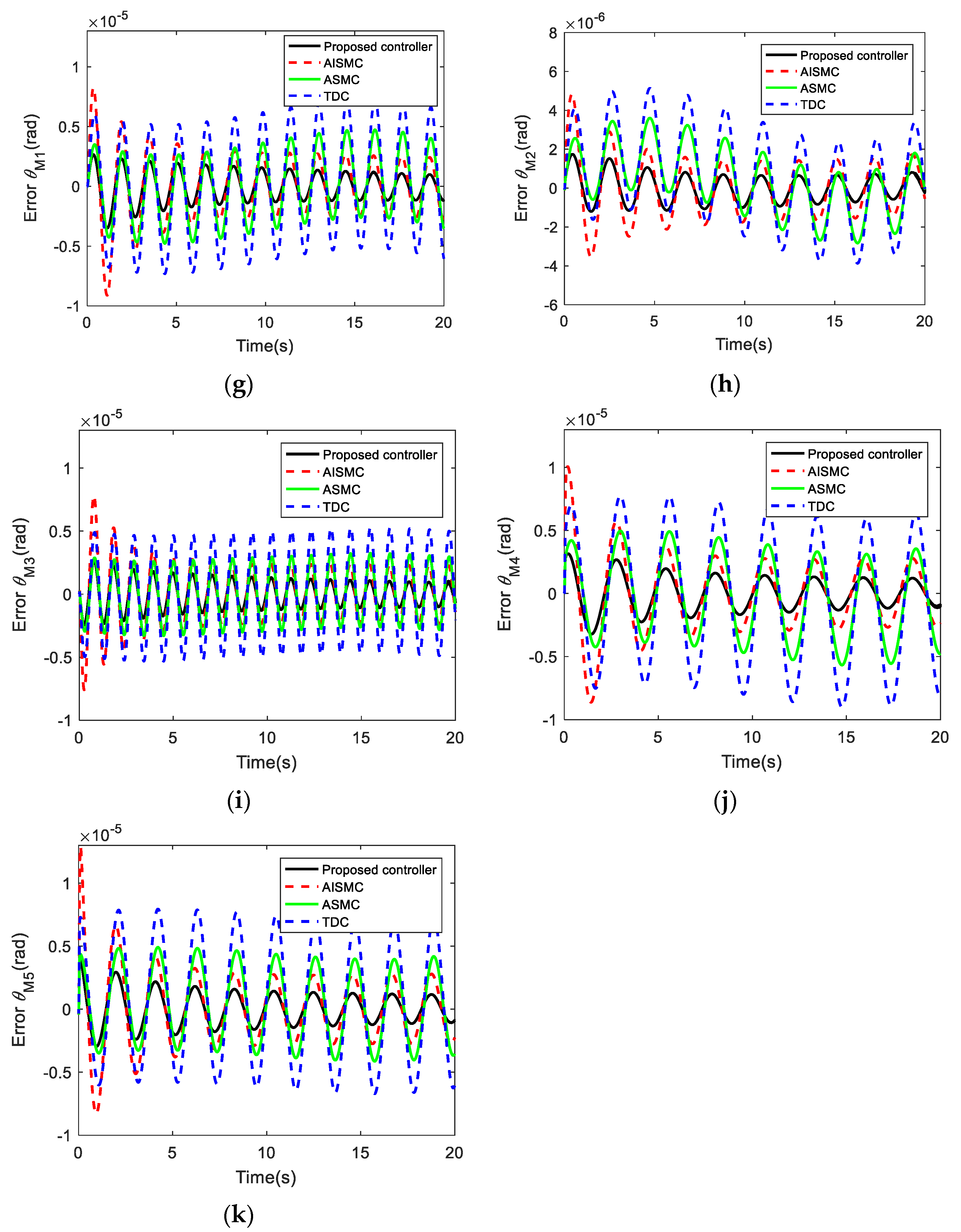
| ITAE | * 1.041 × 10⁻³ | 1.913 × 10⁻³ | 4.725 × 10⁻³ | 6.264 × 10⁻³ | |
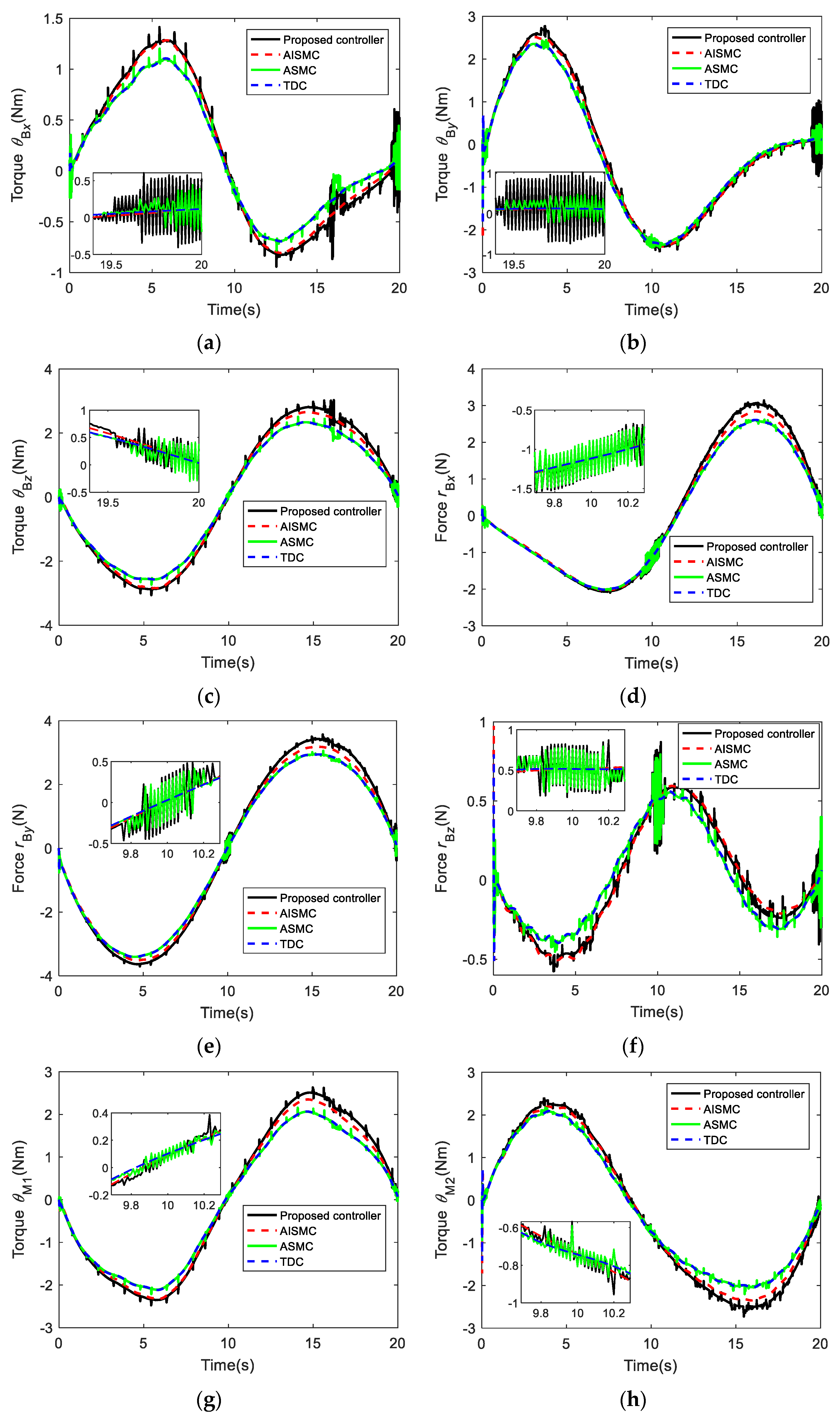
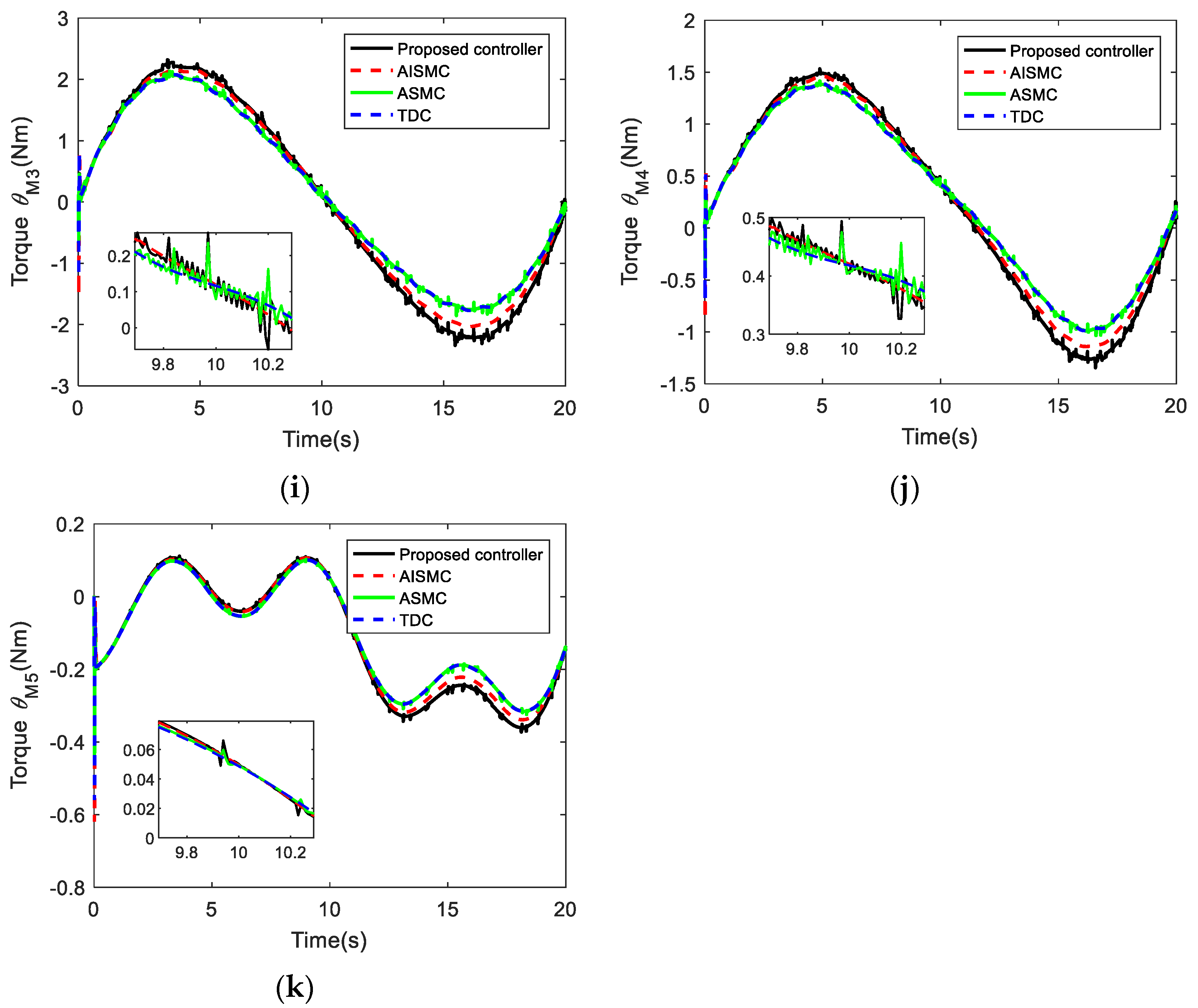
| ISV | 393.9 | 387.2 | 377.6 | * 377.2 | |
| ITAE | * 1.041 × 10⁻³ | 1.912 × 10⁻³ | 4.726 × 10⁻³ | 6.263 × 10⁻³ | |
| ISV | 368.2 | 361.3 | 351.7 | * 351.3 | |
| ITAE | * 1.041 × 10⁻³ | 1.914 × 10⁻⁴ | 4.726 × 10⁻³ | 6.264 × 10⁻³ | |
| ISV | 489.1 | 482.4 | 472.8 | 472.4 |
Publisher’s Note: MDPI stays neutral with regard to jurisdictional claims in published maps and institutional affiliations. |
© 2022 by the authors. Licensee MDPI, Basel, Switzerland. This article is an open access article distributed under the terms and conditions of the Creative Commons Attribution (CC BY) license (https://creativecommons.org/licenses/by/4.0/).
Share and Cite
Zhang, Z.; Li, X.; Wang, X.; Zhou, X.; An, J.; Li, Y. TDE-Based Adaptive Integral Sliding Mode Control of Space Manipulator for Space-Debris Active Removal. Aerospace 2022, 9, 105. https://doi.org/10.3390/aerospace9020105
Zhang Z, Li X, Wang X, Zhou X, An J, Li Y. TDE-Based Adaptive Integral Sliding Mode Control of Space Manipulator for Space-Debris Active Removal. Aerospace. 2022; 9(2):105. https://doi.org/10.3390/aerospace9020105
Chicago/Turabian StyleZhang, Zhibin, Xinhong Li, Xun Wang, Xin Zhou, Jiping An, and Yanyan Li. 2022. "TDE-Based Adaptive Integral Sliding Mode Control of Space Manipulator for Space-Debris Active Removal" Aerospace 9, no. 2: 105. https://doi.org/10.3390/aerospace9020105