1. Introduction
Unmanned aerial vehicles (UAVs), or drones, have grown tremendously in popularity in recent years. Drones are involved in performing missions such as reconnaissance, search and rescue, surveillance, and survey of remote or dangerous locations [
1]. Multirotor drones are popular for their maneuverability, vertical take-off and landing, and hovering capabilities. However, the limited flight endurance restricts multirotor drones from completing time-sensitive and long, persistent missions. This limitation is present in multirotor drones due to their reliance on batteries as their sole power source for their high efficiency, long service life, and simplicity [
2]. Batteries have a low energy density, leading to short endurance and long charging time [
3]. Current commercial multirotor drones can fly for around 25 min with batteries [
4].
Hybrid propulsion technology, including fuel cells, solar panels, fossil fuel, supercapacitors, and battery combinations, has been an area of intense research in recent years [
5]. The hybrid propulsion system combines at least two power sources in a certain way. Hybridization is mainly used in UAVs to increase drones’ efficiency, extend flight time, and reduce energy consumption rates without degrading flight performance.
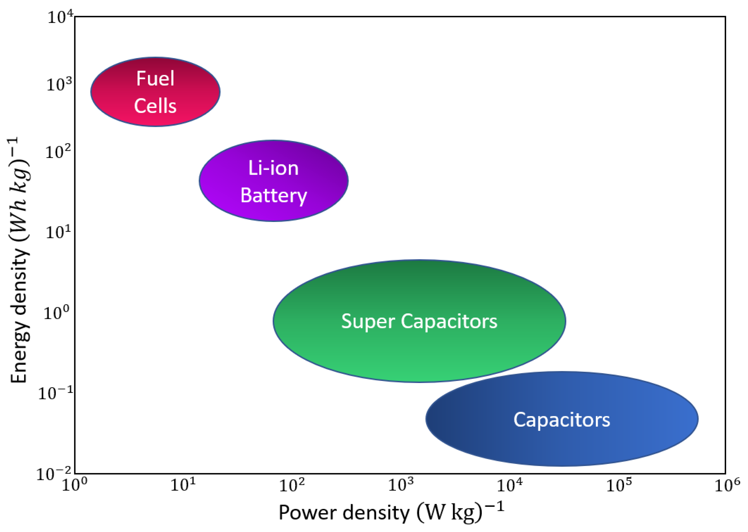
At present, hydrogen fuel cell drones have promising flight endurances but low power densities limit their abilities. The power density represents the power amount that the source can provide in a particular instance [
6]. It has a crucial impact on the drone’s performance because it controls the peak speed, altitude, rate of climbing, and load capacity [
7]. On the other hand, energy density is the amount of power a source can provide within a certain period, directly affecting flight endurance. The energy densities for fuel cells and batteries are higher than the supercapacitors. Therefore, supercapacitors can offer a large amount of power for a short period, allowing the UAV to perform maneuvers requiring fast power response. However, fuel cells and batteries can provide a lower power amount than capacitors but for a longer period.
Figure 1 shows the power and energy densities for different propulsion sources [
8].
Another important source of energy is solar cells, which convert sunlight into electricity. The advantage of this technology is that the transformation process can be carried out without polluting the earth’s environment [
9]. However, these solar cells have lower energy and power densities compared with gasoline. Furthermore, the power obtained from the cell depends on its surface area. Therefore, solar cells are typically implemented on aircraft with wings. Even so, this poses challenges: the area of the wings of an aircraft operating only with solar cells must be larger than the area necessary to generate sufficient lift [
10]. Thus, solar cells are not a promising solution to increasing the flight time of multirotor drones.
For years, batteries with electric drives have been the only propulsion system in UAVs. Electric drives have almost no power plant noise emissions except for propeller noise. They are reliable, clean, simple, and contain no flammable substances [
11]. However, the energy densities for batteries are much lower than some other energy sources, such as gasoline. Thus, the flight endurances for electric UAVs are short and not suitable to perform long-duration flights. Gasoline has a very high energy density at 12.2 kWh/kg compared to lithium polymer batteries (LiPo), which are around 150–250 Wh/kg [
12,
13,
14,
15,
16]. Therefore, harnessing gasoline to provide the lift force for the drones is a desirable solution. Using gasoline to extend the flight time of a multirotor drone is the main object of this paper.
Hence, in this paper, a hybrid multirotor prototype was designed and implemented to exploit the advantages of both gasoline and electric power sources and to balance their limitations. This study aims to determine how the addition of a low-cost commercial-of-the-shelf (COTS) gasoline propulsion system improves the flight time of an electric multirotor drone. The hybrid propulsion system was modeled and simulated to predict flight time and investigate the energy reserves required to achieve the maximum flight time. Furthermore, experimental studies were performed to evaluate the flight time and verify the simulation.
Hybrid-electric propulsion systems have three main configurations: series, parallel, and power-split configuration. Each design has its advantages and drawbacks. In the series configuration, all propellers are driven only by electric motors, and the mechanical energy of the internal combustion engines is converted into electrical energy by the generator. This configuration is relatively easy to control. However, its operating capabilities are limited and its architecture results in inefficiency and increases system weight [
17]. The parallel configuration includes a single drive from each propulsion system. Both are coupled mechanically to drive the same propeller. This configuration allows for a variety of operating modes and permits higher matching to power requirements. However, this configuration suffers from the extra mass of the coupling module and requires an advanced drive control system [
18].
The power-split configuration completely separates the two propulsion systems. This is the simplest method of hybridization, but introduces some structural complexity and requires sophisticated control schemes [
19]. In this paper, the prototype is constructed in the power-split configuration. Its electric and gasoline propulsion systems components independently drive their own set of propellers, and each system has its own fuel source. This setup uses minimal necessary custom parts. Furthermore, this setup is a basic form of hybridization that allows for individual characterization of both propulsion systems.
The remainder of this paper is organized as follows: We review the related work in
Section 2.
Section 3 presents the prototype implementation, including the flight controller modifications to accommodate the gasoline engines. The characterization process of the actuators is introduced in
Section 4 to investigate their thrust output relative to their energy consumption.
Section 5 discusses the minimum thrust required from each propulsion system to achieve a reliable flight performance. After that, the system model determines the recommended battery capacity and fuel volume to carry onboard in
Section 6. The simulation results are verified experimentally and discussed in
Section 7. Finally,
Section 8 summarizes the conclusions and presents future work.
2. Related Work
Recently, drones have shown promise in various fields. Therefore, flight endurance is the focus of several types of research. Said research provided several techniques to increase the flight time, such as swapping [
20,
21], tethering [
22,
23], laser-beam inflight recharging [
24,
25], and hybridization [
26,
27,
28]. Swapping is a technique that involves replacing a discharged battery with a charged one, but this technique requires stationary or mobile ground stations distributed in specific locations. In tethering, the endurance is unlimited because the flying drone will be connected directly to the power supply ground station, but this technique restricts the mobility of the drone. In the laser beam technique, flying drones receive light power through laser beams emitted from ground stations. While less restricting than tethering, this technique still limits the drone’s range.
Hybridization is a technique that combines the advantages of two or more energy sources to increase flight endurance and energy usage efficiency and achieve high-performance operations. Furthermore, no ground stations are necessary as in the previous techniques. Koster et al. developed a green aircraft technology called Hyperion [
29]. This 3-m aircraft includes a new hybrid gas/biodiesel–electric power train operating in internal combustion, hybrid, or electric mode. Gong et al. presented a flight test of a triple-hybrid propulsion system UAV consisting of a fuel cell, a battery, and a supercapacitor [
30]. This triple hybrid propulsion system combines the performance benefits of each power source. These sources are installed in parallel to enable load sharing between each of the three power sources. Harvey et al. showed that although the application of photovoltaic cells on the aircraft caused a slight increase in weight, the addition of photovoltaic cells to the hybrid drone (fuel cell and battery) would increase the flight endurance as it saves 59% of the h2 fuel [
31]. Shiau et al. improved an experimental UAV flight endurance by designing a battery-backed solar power management system to supply the necessary power to the onboard electronic system components [
32].
Some researchers have combined gasoline and electric power in UAVs due to the enormous endurance they can achieve with gasoline. Lu et al. introduced a novel hybrid gas–electric propulsion system for a micro triple tilt-rotor vertical take-off and landing (VTOL) prototype [
33]. This UAV can operate as a parallel hybrid configuration according to the driving conditions in motor mode, engine mode, or hybrid mode. However, all energies are used directly. In other words, there are no fuel power generation processes. National Cheng Kung University developed another hybrid gas–electric drone in 2017 [
34]. Preliminary tests have shown that it can fly for about 60 minutes with no payload. This research focuses on controllability and targets this amount of time. The number and arrangement of rotors, number of batteries, thrust distribution, size, and weight of this drone significantly differs from the prototype in our study.
3. Prototype Implementation
The gasoline–electric hybrid drone was constructed from the Tarot 680 Pro hexacopter platform, 695 mm in diameter. First, the prototype was constructed as a fully electric quadcopter. It was characterized, and then the gasoline system was added to create the hybrid prototype. Although built for electric-only drones, the Pixhawk was suitable for this UAV. Pixhawk is a high-performance, all-in-one control system that allows a drone to maneuver agilely [
35]. In addition, it has open-source hardware and software, enabling us to modify the software to accommodate the gasoline engines of the drone.
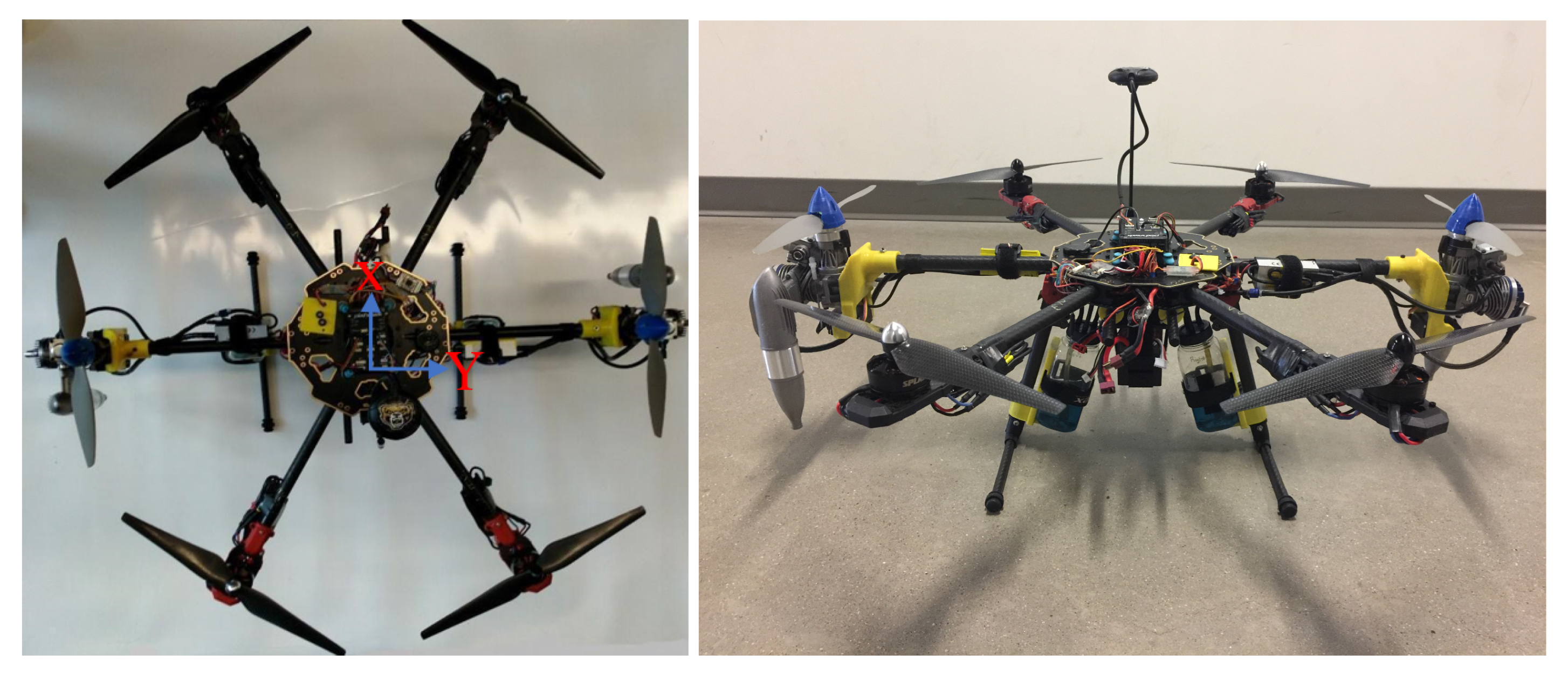
Figure 2 shows the prototype with the two gas engines installed on the Y-axis of the drone frame to distribute their weights, and four electric motors placed as the quadcopter. Each gasoline engine weighs 0.96 pounds, and the entire gas system, including fuel tanks, mounts, and driving components, weighs 4.65 pounds. The fundamental drone components, including the frame and electrical system, weighs 5.33 pounds. In total, the hybrid drone weighs 9.98 pounds.
Despite the 87% increase in weight from the addition of the gasoline system, thoughtful operation of the hybrid propulsion system can significantly increase the drone’s flight time. The gas engines operate on a constant thrust to provide the majority of the lifting force. Hence, the electric motors provide stability and maneuverability, as they have a faster response time. The gas engines and electric motors independently produce thrust, so in
Section 5 we identify the optimal thrust ratio between the two propulsion systems.
3.1. Electric Propulsion System
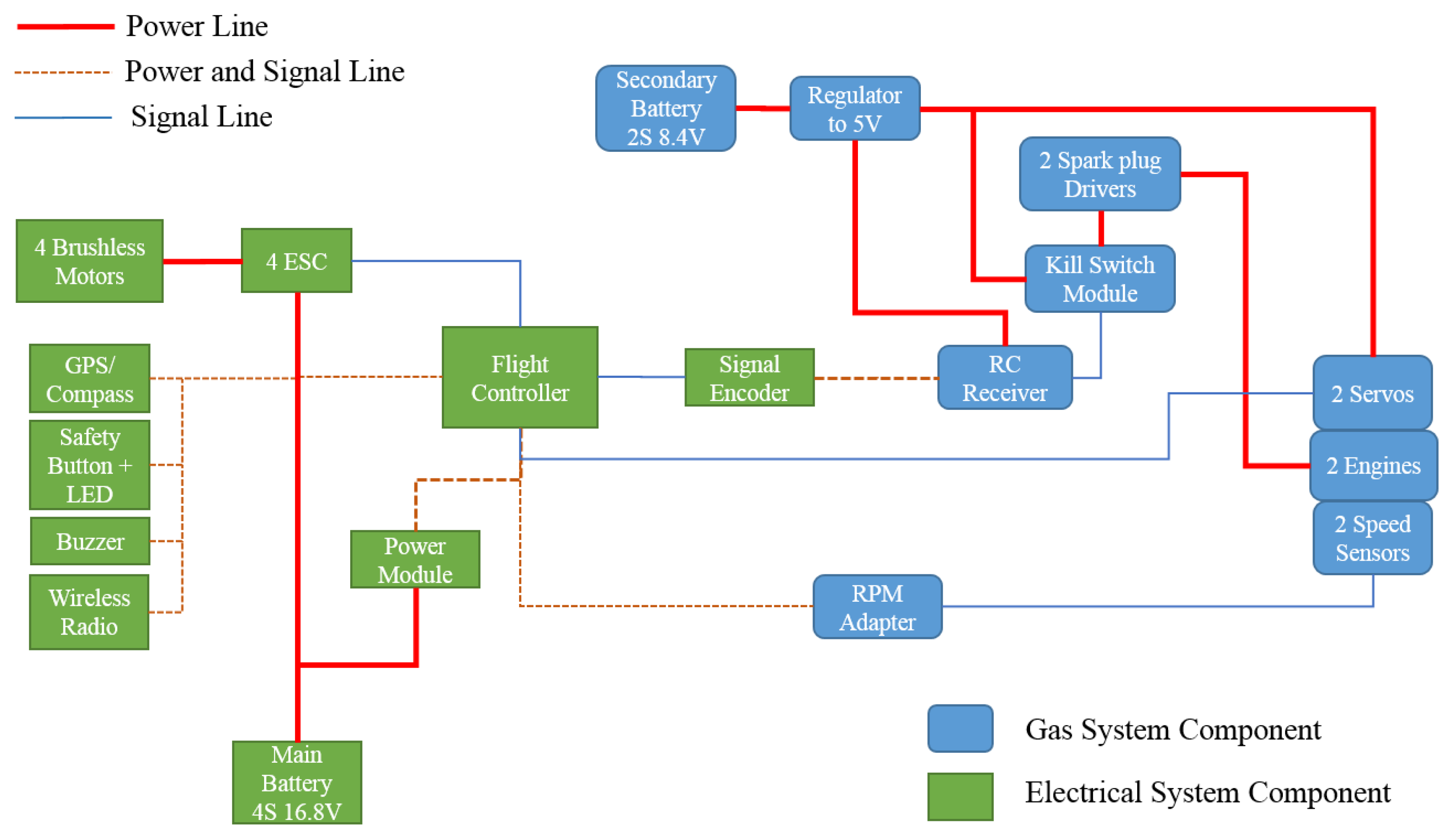
The electric propulsion system consists of four brushless Swellpro 3508 650 kv DC motors with DJI carbon fiber 12 × 4.2 propellers, which comply with the recommendations by the Tarot 680 distributor. These motors primarily control the drone’s stability and maneuverability, and they produce partial thrust. A main 4 s 7500 mAh LiPo battery is used to power these motors through four electronic speed controllers (ESCs) designed to invert the DC power to a three-phase source to control the motors.
Figure 3 illustrates the wiring diagram between the electrical components on the prototype. The main battery also powers the flight controllers and the primary electronic devices. A secondary, lower voltage battery powers the gas system’s electrical components such as servos, spark plugs, and engine safety failsafe.
Several procedures have been taken on this prototype to protect it from electromagnetic interference (EMI). EMI may arise due to the high current running through the power lines, which can heavily disturb the signal lines, particularly the magnetometer sensor reading, which is essential to determine the yaw heading of the drone. Therefore, a separation between signal and power lines was implemented as often as possible to mitigate the EMI disturbances. Furthermore, the magnetometer sensor was installed 17.5 cm above the drone platform, as shown in
Figure 2.
3.2. Gas Propulsion System
The two EVO10GX2 gas engines provide most of the lift force for the drone. This engine is a 10 cc single-cylinder 2-stroke engine. It is relatively small in size and light in weight to fit into the tight space of the drone [
36]. The gasoline engines come with an ignition module, ignition sensor, spark plug, and a high-resolution Hall-effect sensor, which determines the spark plug firing time and provides an accurate reading for the engine’s revolutions per minute (RPM). Setting the RPM occurs by controlling the air intake on the carburetor through a servo attached to a single rod.
The fuel for this engine requires a mix of 20:1 gas to oil, and 87 octane is suitable for this engine. Each gasoline engine came with an 8 oz fuel tank from Evolution Engines. The manufacturer also produces solutions to avoid the fuel bubbles problem. The fuel bubbles may cause quivers, sporadic instability in the gasoline engine, and maybe a shutdown [
34]. EVO10GX2 comes with a felt filter clunk used in the fuel tank to stop the air bubbles from reaching the carburetor via the fuel delivery pipes. This filter is pivotal and is designed to give a reliable flight for the hybrid drone.
Installing the two gas engines on the opposite sides of an electric quadcopter requires that their propellers’ rotation directions are opposite to each other. One is clockwise, and the other is counterclockwise to cancel the torque and minimize the yaw correction provided by the motors. One difficulty we faced with these gas engines was the rotation direction. As manufactured, these gas engines rotate only in the counterclockwise route. Therefore, we manufactured a new crankshaft to reverse the rotation direction of one gasoline engine. We replicated the original crankshaft design but repositioned the air intake hole to the mirrored location of the original crankshaft. The engine successfully rotates in the clockwise direction after reallocating the Hall-effect sensor for proper ignition timing.
The gasoline engine’s fuel flow was tuned manually by adjusting the low-speed and high-speed needles. Therefore, under the same conditions, each engine performs somewhat differently. However, the modified engine also showed less fuel efficiency due to the imperfect replication of the crankshaft and the difficulty of replicating the exact size of the air intake hole.
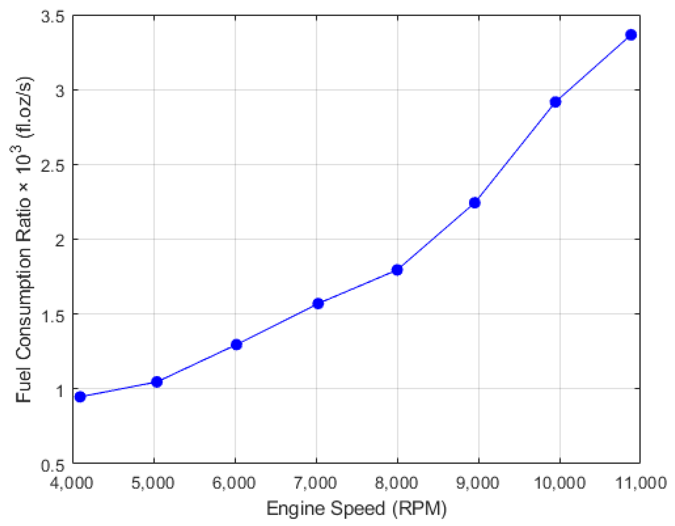
Table 1 shows the fuel consumption rates for both gas engines. The engines were tested outdoors with identical Gefman 11 × 4.5 plastic propellers, discussed below.
Selecting the appropriate propellers puts less stress on the engines and economizes fuel consumption. As the recommended propellers are designed only for counterclockwise rotation, we chose new propellers due to the modification applied to one gasoline engine to rotate within the clockwise course. The recommended propeller for these engines ranges from 10 × 6 to 13 × 8 [
36], and they use propellers designed for electric motors. A Gefman 11 × 4.5 plastic propeller was selected as it has a low pitch value with less turbulence, thus providing more stability for the drone, less fuel consumption, and increasing flight time [
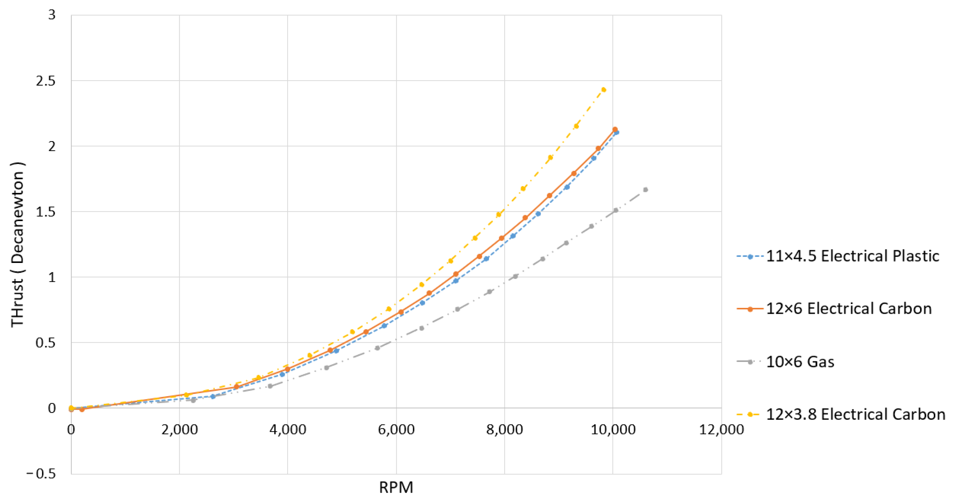
37]. Furthermore, it has an appropriate size that will provide the lift needed for the drone without consuming much fuel. The 11 × 4.5 electrical plastic propeller performed similarly to the 12 × 6 electrical carbon propeller, but it is more durable. The material used in the propeller’s construction may affect its efficiency at various RPMs.
Figure 4 shows an experimental test for different propellers and shows that the 11 × 4.5 plastic propeller originally manufactured for electrical motors was suitable for the gas engine. Note that 12 × 3.8 has better thrust than 11 × 4.5, but it consumes more fuel as it sweeps more air and responds slower to the input.
Because the engines are not intended for implementation on a drone frame, placing them on the drone’s y-axis necessitated a novel mount design. The mount needs to connect to the drone’s cylindrical arm and have flat surfaces to mount the engine and carburetor-controlling servo. Two design iterations are shown in
Figure 5. Initially, an aluminum mount was designed for robustness. Holes were drilled out to reduce its weight, but each mount still weighed 0.22 pounds. A lightweight and easy-to-manufacture alternative used ABS plastic, which was 3D printed into a mount. This is significantly lighter in weight, but ABS plastic has a lower Young’s modulus than aluminum, thus making it more susceptible to fracture. Young’s modulus, which is essentially the material’s stiffness, is crucial to be considered with this mount [
38]. After performing finite element analysis to locate the weakest spot, a flange was attached to this mount to reinforce it. The final mount, made of ABS plastic, weighs 0.10 pounds. Hence, this mount is light in weight and less susceptible to fractures.
Even though gas engines can lead to increased flight time, the gas engine’s vibrations can severely affect the drone’s performance. These vibrations could dramatically affect flight stability, break the engines apart at high RPMs, and damage the frame structure [
39]. Rubber mount shock absorbers with bolts extending from both sides of a rubber center were placed between the gas engine and its mount to mitigate these vibrations. These absorbers are light in weight and have a large elasticity which can effectively protect the structure. Various shock absorbers are available, including spring dampers, wire rope isolators, and air isolators. As a result, the shock-absorbing system might be developed further to assure structure longevity.
The flight controller, Pixhawk, is responsible for providing reliable flight stabilization. To ensure a stable flight, the vibrations read by the accelerometer sensor should not rise above/below ±3 m/
, which confirms that the shock absorbers are necessary for drone stabilization.
Figure 6 plots the vibrations along the drone’s x-axis when the engines run for a while. As shown in
Figure 6, the pulses are excessive before lifting off the ground, caused by the collision between the drone’s frame and the floor. However, the vibration experiences a dramatic reduction when leaving the ground and stays within limits.
3.3. Controller Modifications
The primary electronic device on the prototype is the flight controller, Pixhawk. It is a high-performance autopilot device provided with an ARM Cortex-M4 processor running at 168 MHz, executing advanced control algorithms [
40]. Due to the Pixhawk being open source for both hardware and software, it was suitable for the prototype, as modifying the software is necessary to incorporate the two gas engines.
The essential role of the gas propulsion system is to provide the lift force for the prototype. It is also necessary that the two gas engines rotate opposite each other to minimize the yaw correction provided by the motors. The engines received the desired RPM from the user input. However, the RPM for both engines will not be identical because each gasoline engine was manually tuned. Hence, two PI loop functions were added to Pixhawk’s software v1.8.2 to control the engines’ RPM.
The prototype’s Pixhawk was configured for a quadcopter, thus providing the automatic stabilizing feature for the electric propulsion system. The two PI loop functions receive the RPM feedback readings from the Hall-effect sensors and adjust the servos that control the throttle opening of the engine. Several experimental tests were conducted to tune the performance of these PI functions and achieve a ±200 RPM error margin, which is shown in
Figure 7. The derivative gain was not used because the inertia of the gas engines rendered D largely ineffective in providing stability. Note that in
Figure 7 the response time for the gas engines to go from around 4400 RPM to 8000 RPM is approximately 3 s. However, this is not a primary concern as the gas propulsion system is intended to provide constant thrust during the flight.
5. Gas/Electric Ratio Optimization
One of the most significant factors affecting the hybrid prototype’s flight time is the thrust required from each propulsion system. The gas-to-electric thrust ratio is a parameter that expresses the thrust output required from each propulsion system. For example, a 75:25 thrust ratio means the gasoline propulsion system produces 75% of the total thrust force, and the electric propulsion system produces the remaining 25%. Operating at any given thrust ratio affects the rate of fuel and the battery capacity consumed.
Since the prototype should achieve maximum flight endurance, the motors should consume enough current to stabilize the drone and fly agilely. Due to the prototype’s significant moment of inertia (MOI), as it is equipped with two gasoline engines, the torque needed to rotate the drone and recover from any disturbance is high; thus, more current is required for the motor to stabilize the drone. As a result, the thrust produced by the gasoline propulsion system was experimentally selected by determining the minimal amount of current required for the electric motors to stabilize the drone effectively.
Several simulations and experiments were conducted to find the optimal thrust ratio. Furthermore, this ratio determined the amount of fuel in each tank. Filling the tanks with extra fuel decreases flight time and consumes more current from the battery as the drone’s weight increases. Hence, filling the tanks with the exact amount of fuel makes the prototype deplete all the energy reserves simultaneously and achieve maximum flight time.
6. System Modeling
The mathematical model of the prototype was simulated and analyzed utilizing MATLAB Simulink. The model investigated how the weight and energy density of the gasoline and battery carried onboard affected the prototype’s flight time for different gas-to-electric thrust ratios. Adding further energy reserves requires more thrust from each propulsion system to produce the necessitated lifting force and stabilization. The simulation showed that maximum flight time is achieved when the drone operates at a high gas-to-electric thrust ratio and all the energy reserves are depleted simultaneously.
6.1. Model Development
Mathematical model simulation can efficiently predict the prototype behavior without extensive testing.
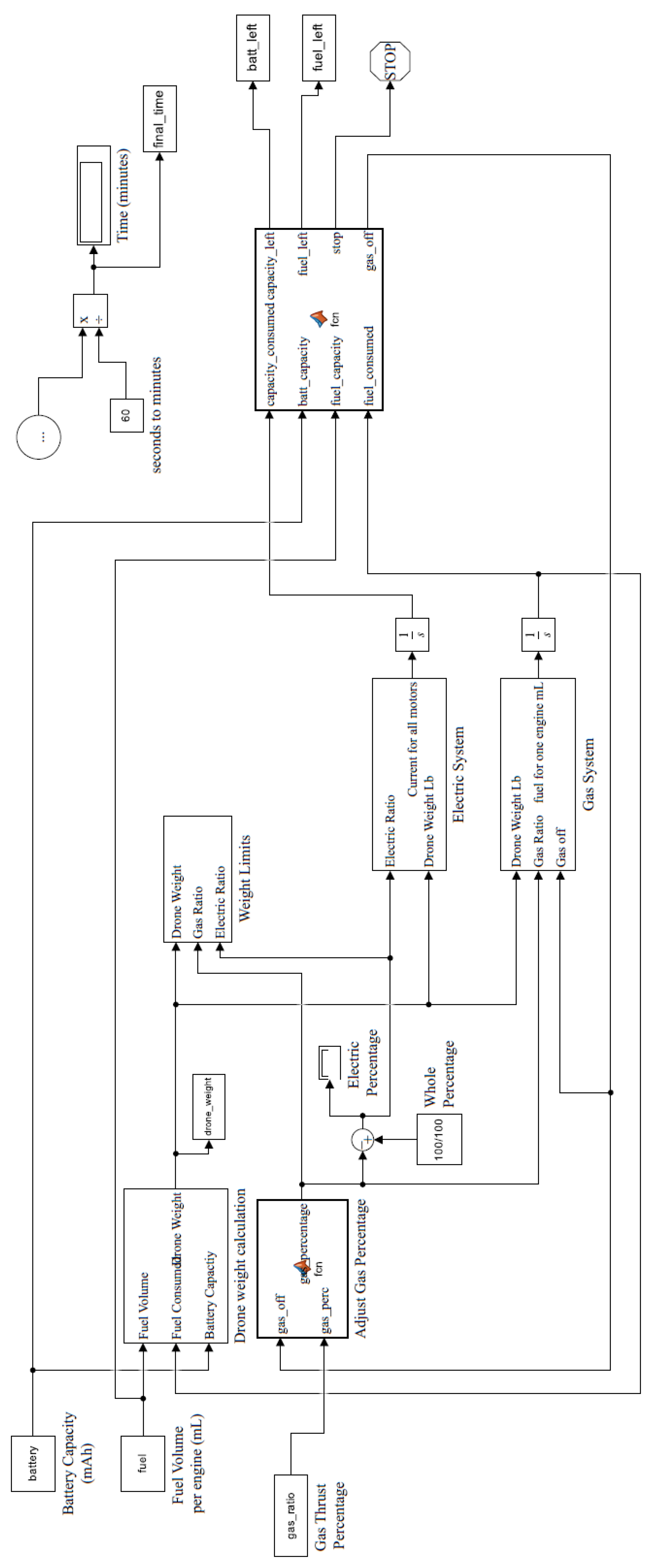
Figure 14 shows the model that examines the relationship between thrust output, energy consumption rates, and the varying prototype’s weight throughout the flight. Battery capacity, fuel volume, and gas-to-electric thrust ratio are the model’s inputs, with the flying time being the output. For simplicity, the only operating scenario considered was hovering in ideal conditions with no external disturbances, so the model neglects the drone’s responsive behavior and physical dimensions.
The required thrust from each subsystem is determined by the weight of the drone and the gas-to-electric thrust ratio. If the required thrust exceeds the motor thrust limit, a stop signal is generated. In other words, if the simulation inputs of fuel weight and battery capacity exceed the maximum weight that the motors/engines can lift, the simulation will be terminated.
If the inputs will allow the prototype to fly, the next relevant blocks are the gasoline system, electric system, and drone weight calculation blocks. The gasoline and electric system blocks employ the equations derived by the characterization processes for each actuator to calculate the energy reserves needed when a specific thrust force is required. Third-degree polynomial functions were fitted for this purpose using the MATLAB curve fitting toolbox. The simulation multiplies the performance of a single electric motor by four when calculating the amount of energy required, which is consistent with the ideal hovering assumption. Furthermore, the model assumes that the battery voltage stays at 15.34 V for the entire simulation run, which is the same voltage used in the motor characterization test. In the gasoline system block, both gas engines are assumed to perform according to the unmodified engine. This decision was made to demonstrate the potential of the prototype in the case where engines are commercially manufactured in both clockwise and counterclockwise rotation directions.
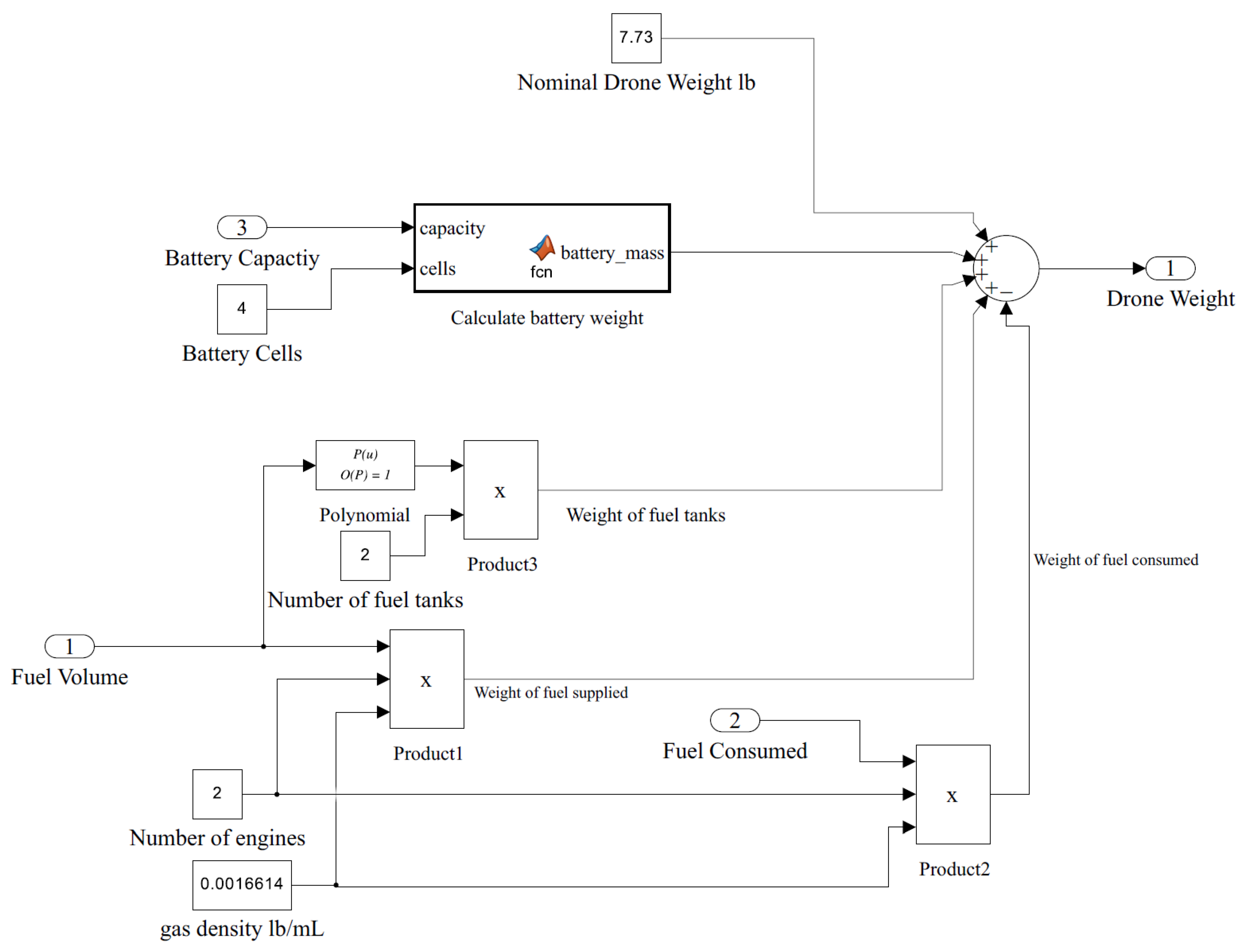
The drone weight calculation block is crucial in the simulation because multirotor drones must actively overcome their weight. It is shown in detail in
Figure 15. The initial weight is calculated from the fuel amount, battery capacity, and fuel tank size while keeping all other fixed weights. The battery mass depends on cell count, cell configuration, and cell capacities and is calculated using the following equation [
42]:
where
c is the battery capacity,
s is the battery cell count,
P is 0.026373, and
P is 2.0499 × 10
. The weight of the fuel tank was estimated using a proper function based on vendor specifications [
43]. Note that in
Figure 15, the only variable that changes the drone’s weight while the model is running is the weight of fuel consumed. As the prototype consumes fuel, its weight decreases, so the drone weight calculation block iteratively calculates the prototype’s weight. This decrease in weight results in less thrust required to lift the prototype, thus prolonging flight time.
The weight limits block after the drone weight calculation block determines whether or not the required thrust from each motor engine can be achieved. This is important for determining whether the inputted battery and fuel amounts are feasible for hovering.
The final block in the simulation compares the energy consumption to the remaining fuel and battery capacity. The simulation terminates the flight when the prototype entirely consumes the battery. The prototype can fly in two modes, either hybrid or fully electric. Therefore, the simulation also ends if there is still energy in the battery, but the fuel is depleted and the electric motors’ total thrust is insufficient to lift the prototype.
6.2. Simulation Results
The hybrid gasoline–electric hexacopter performance was evaluated by conducting extensive simulations.
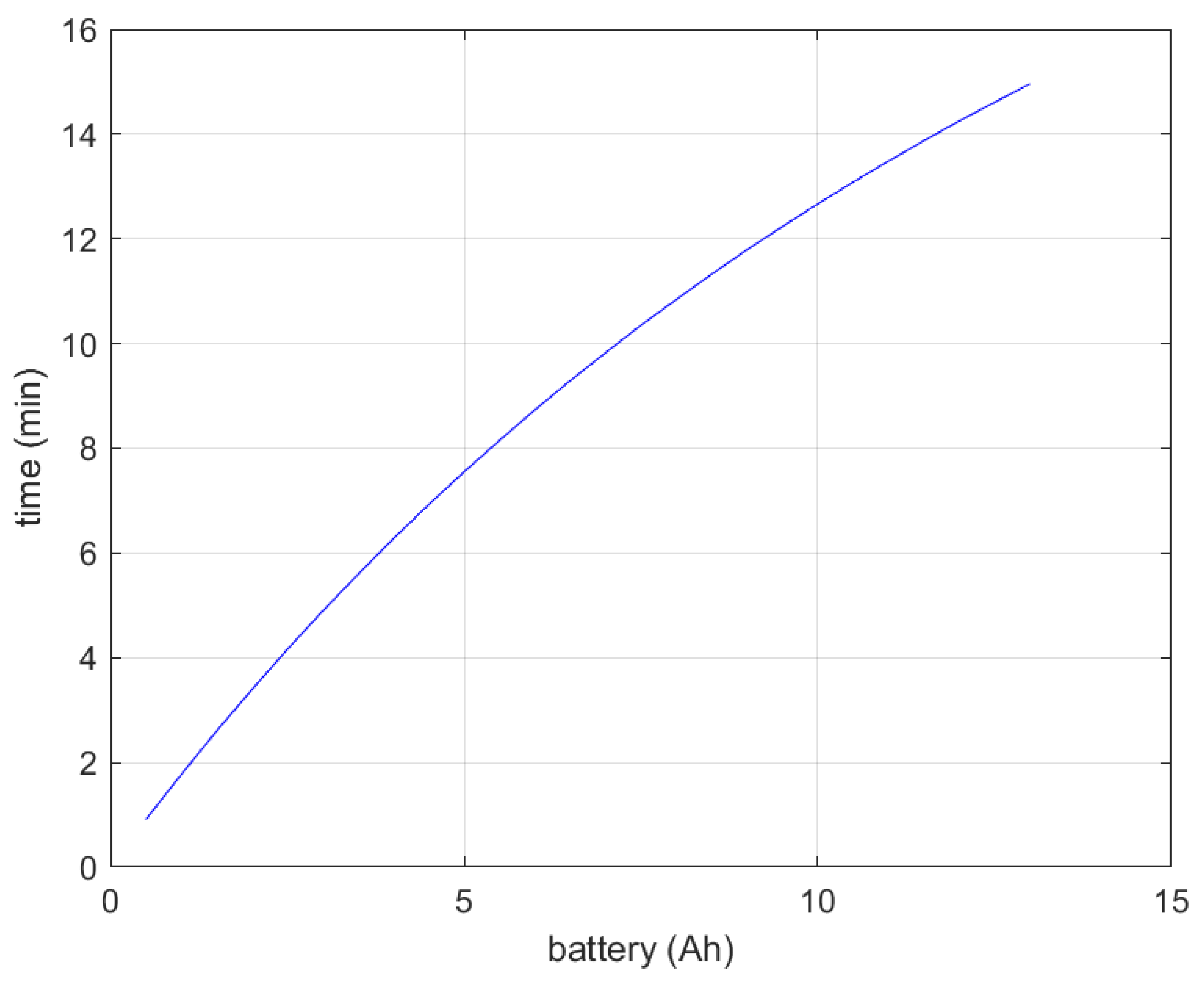
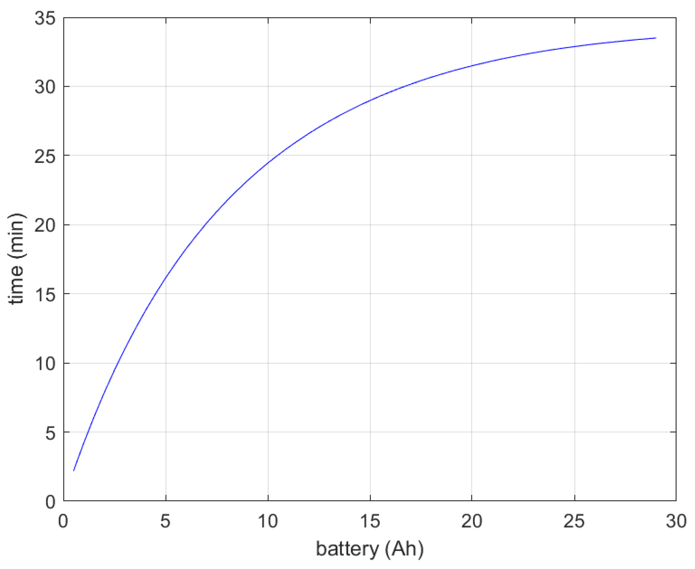
Figure 16 shows the fully electric flight simulation while the gasoline propulsion system is off. This result indicates that the maximum battery capacity the prototype can carry is 13 Ah. Thereafter, more thrust is required to overcome the drone’s weight, which the electric motors cannot provide.
Figure 17 shows the fully electric flight simulation when the gasoline system is excluded from the drone. This decreases the drone’s weight by 5.33 pounds and has a maximum flight time of 33 min. This figure aims to show the flight time improvement achieved by adding the gasoline propulsion system.
One crucial function of the simulation is determining the proper weight of fuel and battery capacity for a specific gas-to-electric thrust ratio. This ensures no extra weight is carried onboard and results in maximum flight time.
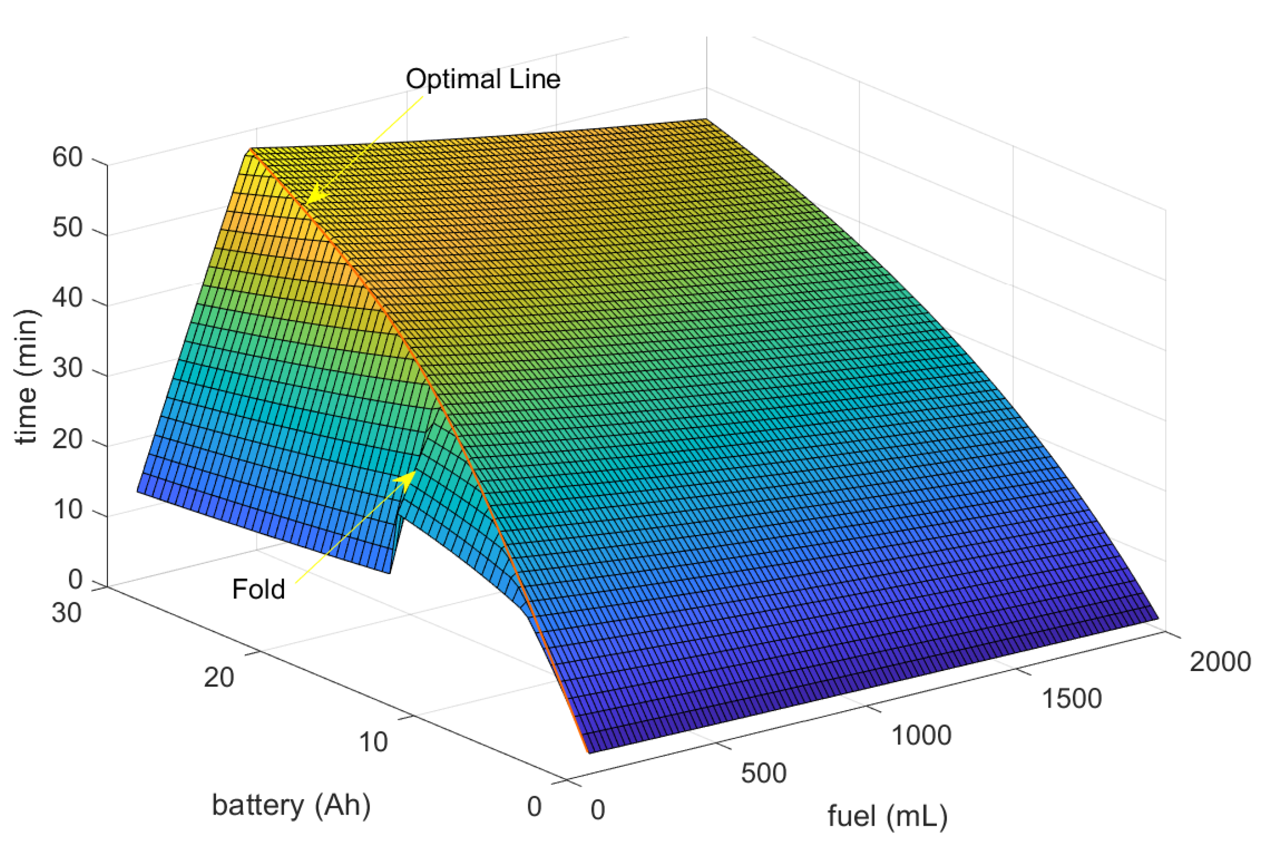
Figure 18 illustrates the flight time for a range of fuel volumes and battery capacities with a 50:50 gas-to-electric thrust ratio. Note that there is an optimal line that bends the 3D plot into a pyramid shape. This line shows fuel and battery capacities that are depleted simultaneously, which provides optimal fuel and battery capacity estimates to carry onboard the drone. Using these points on this line facilitates the hybrid electric and gas propulsion systems design for drones with the same components and configuration as the introduced prototype.
The region to the right of the optimal line in
Figure 18 shows the points at which the battery drained first. Meanwhile, the left part represents the points when fuel is exhausted first. An empty fuel tank forces the prototype to switch to a fully electric operation. However, the total thrust generated by the electric motor is insufficient to lift the prototype when the battery is above 13 Ah, as previously shown in
Figure 16. This case is clearly shown in
Figure 18 as there is a step down to lower flight times after switching to the fully electric operation with a 13 Ah battery or higher. The 50:50 ratio achieves a simulated flight time of 26 min with a 7500 mAh 4-cell LiPo battery and 90 mL of fuel. This short flight time is because the 50:50 gas-to-electric ratio is insufficient to utilize the gasoline propulsion system. Furthermore, adding more gasoline fuel at this rate will increase the prototype’s weight, reduce flight time, increase pressure on the electrical system to stabilize the drone, and drain the battery faster.
Increasing the thrust required from the gasoline engines is necessary to utilize the gasoline propulsion system further. This increase allows the gasoline engines to provide more lift to the prototype and reduces the current drawn by the electric motors.
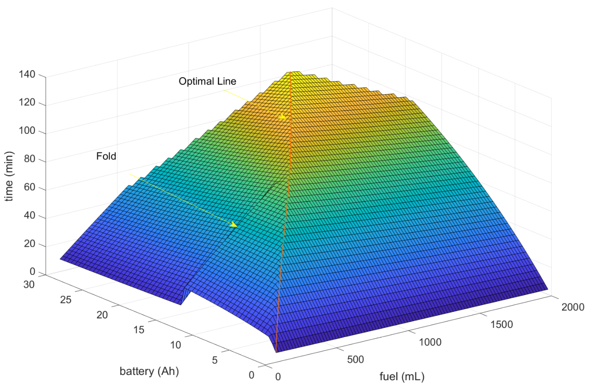
Figure 19 shows the flight times after increasing the gas-to-electric thrust ratio to 75:25. This ratio achieves a simulated flight time of 60 min with a 7500 mAh 4-cell battery and 480 mL of fuel, 240 mL in each tank, which equals the prototype’s fuel tank size. As a result, this ratio achieved nearly triple the drone’s flight time with no gas propulsion system, as shown previously in
Figure 17. Following the optimal line provides a reasonable estimate of the required energy reserves. Replacing the battery with a 15,000 mAh LiPo battery and increasing the fuel tanks size to accommodate 470 mL of fuel, 940 in total, caused the simulated flight time to rise to nearly 98 min instead of 28 min achieved with the electric-only flight time.
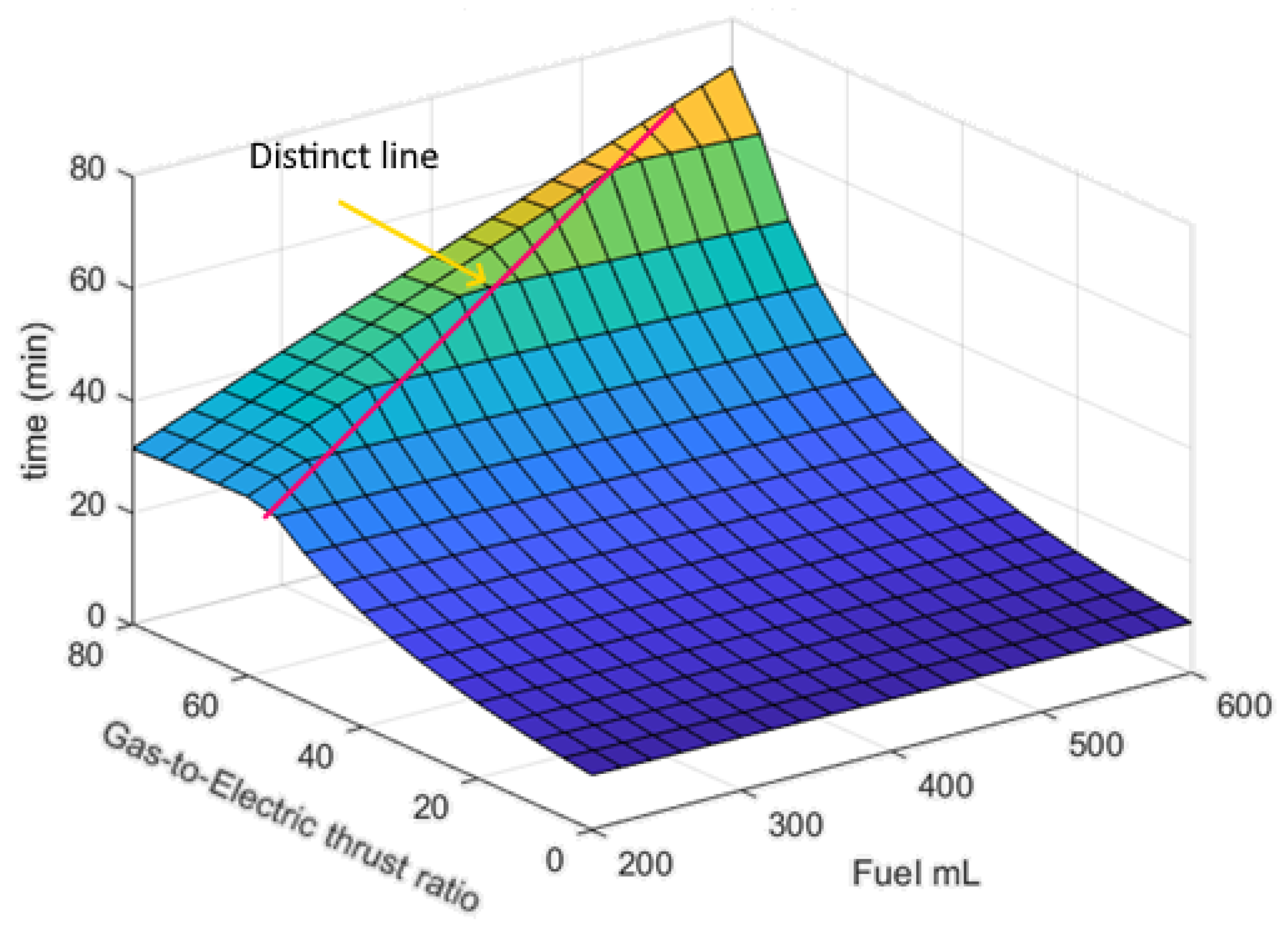
The simulation also determines the optimal gas-to-electric thrust ratio for a given battery capacity and fuel tank size. The prototype is equipped with a 7500 mAh LiPo battery and two 8-ounce, 240 mL fuel tanks.
Figure 20 shows the flight times using a 7500 mAh LiPo battery with varying fuel volumes and thrust ratios. It also shows the optimum gas-to-electric thrust ratio for the prototype, which is found at 75:25 for this particular battery capacity. A distinct line that divides the plot into two parts represents the optimal gas-to-electric thrust ratios for the 7500 mAh battery with different fuel amounts. The left side of this optimal line shows that as the gas-to-electric thrust ratio increases, fuel is consumed before the battery is depleted. Hence, a reduction in the flight times occurs as the prototype switches to function fully electrically, causing battery drain. Note that the prototype MOI is high due to the presence of the gas propulsion components. Experiments show that increasing this ratio beyond 80:20 will impair the stability of the drone. Reducing the electric thrust below 20% will slow down the angular recovery rate when stabilizing the drone and affect maneuverability performance.
7. Experimental Evaluation and Conclusions
Several experiments were performed to evaluate the effect of the gasoline system on the prototype’s flight time. These included restrained tests that forced the prototype to hover ideally and free flight tests where the prototype was faced with true-to-life conditions. Furthermore, experiments were compared to the simulation results to assess the validity of the model and predict the drone’s flight time in ideal conditions.
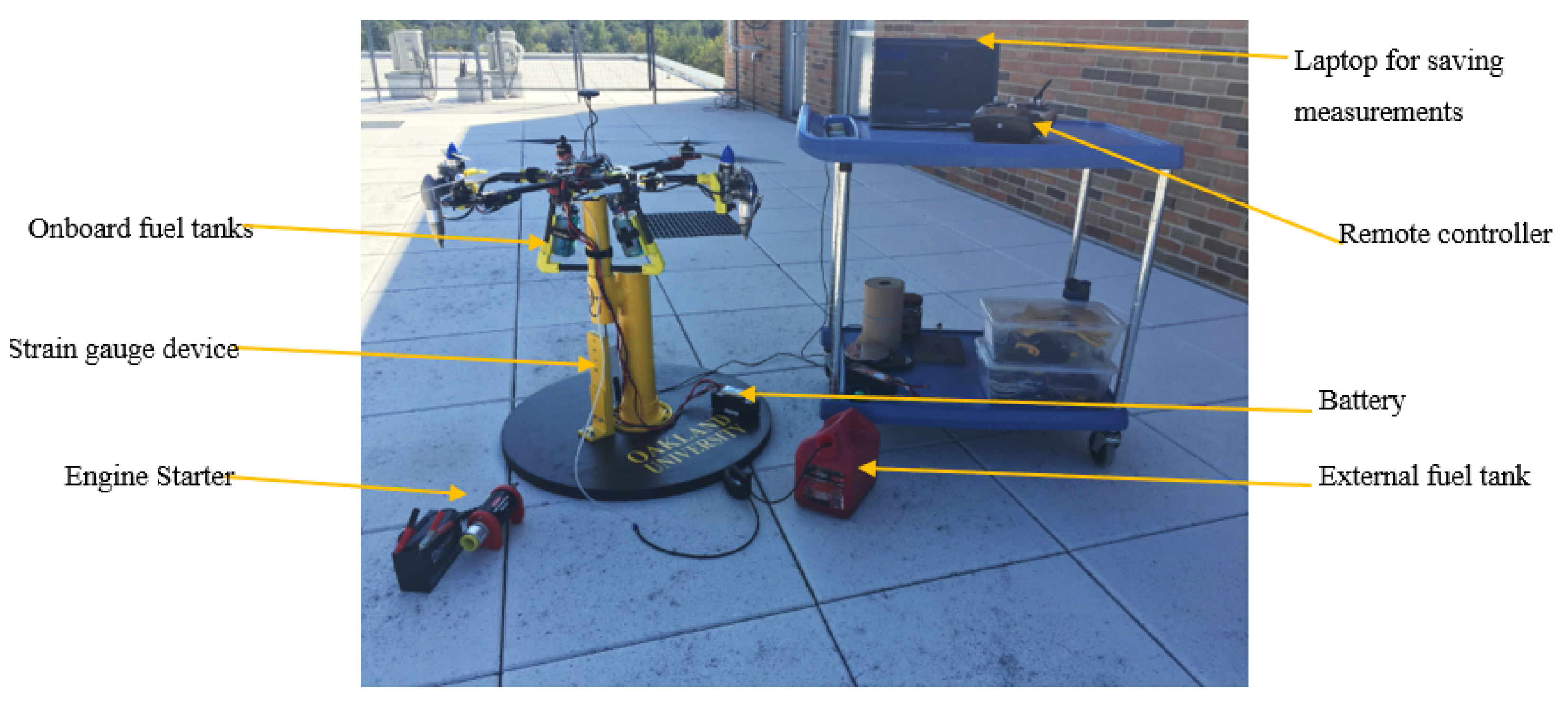
Figure 21 shows the components used when testing the drone in ideal hovering conditions. The test stand restricts roll, pitch, and yaw movements to mimic the hovering conditions in the simulation, and the drone is directly coupled to a strain gauge to measure its pulling force, which corresponds to the lift force produced by the drone. When the lifting force on the strain gauge incrementally exceeded the drone’s weight, the drone was considered to be hovering. The Pixhawk collects the overall current consumption of the electrical components and RPMs for the gasoline engines. Since one of the gasoline engines has a modified crankshaft, which reduces its efficiency, the data analysis only considered the unmodified gasoline engine’s fuel tank. This is consistent with the assumption made in the simulation model and serves to predict the behavior of the prototype in the ideal case where engines are available in both rotational directions.
To operate at a specific thrust ratio, the gas engines’ speed and the current drawn by the electric motors were determined from the simulation’s calculations. The test began with the startup of all actuators at a low speed. The RPM of the gasoline engine was increased via the remote control to reach the required RPM. Then the electric motors’ speed was increased and tuned until the total current measurement matched the current requirement specified in the simulation. The strain gauge measurement verified that the prototype was “hovering”. Timing began when the gasoline engines started and continued until one or both energy reserves were completely depleted. The recorded time represented the flight time of the drone.
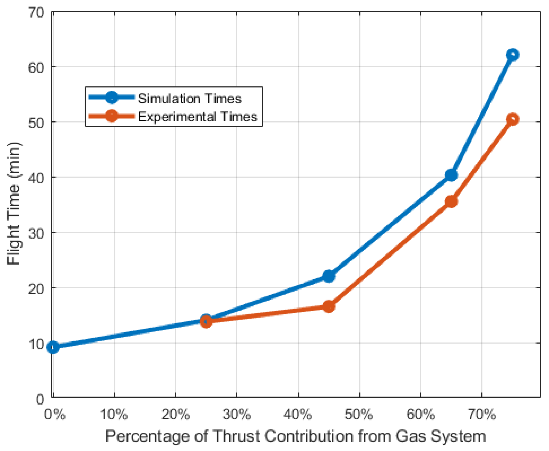
Figure 22 shows how four experimental tests compare the simulation model at various gas-to-electric thrust ratios. All tests were conducted with a 7500 mAh battery, a full 8-ounce fuel tank on the unmodified engine, and an external fuel tank on the modified engine. As expected, long flight times were achieved with high values for the gas-to-electric thrust ratio. As the gas-to-electric thrust ratio was increased, the current draw on the motors decreased while dependence on the gasoline system increased. Because gasoline has a higher energy density, the prototype was able to operate longer when it derived more of its lift from the gasoline system, resulting in significant flight times. A total of 50 min of operation was achieved on the test stand with a 75:25 gas-to-electric thrust ratio, which was determined to be the optimal gas-to-electric thrust ratio. This flight time is a significant improvement upon battery-only flight times and shows that hybridizing a multirotor drone with a gasoline system can increase flight time.
Note also that the actual flight times in
Figure 22 almost consistently show lower values than the simulation results. While both the experiment and the model enforced conditions for hovering, there are several minor discrepancies between the two that likely aggregate into the observable difference in
Figure 22. First, the assumptions in the simulation do not reflect how the voltage changed in the battery during operation. Next, weather conditions were not included in the model. Temperature and humidity affect the performance of the engines and thrust output of the propellers, which likely caused them to underperform in comparison to the characterization tests. Nevertheless, the matching trend between the simulated and experimental results shows that the model captured the basic behavior of the hybrid prototype. Thus, the suggestions made from the simulation in
Section 6.2 can be used as a starting point for future gasoline–electric hybrid drone designs.
To compare the flight time of the prototype with conventional drones,
Table 2 shows select fully-electric drones from different manufacturers. It is apparent that the hybrid gasoline–electric multirotor drone can outlast the other multirotor drones. More specifically, the hybrid prototype provides a 25% longer flight time when compared to one of the top-performing commercial drones, the DJI Matrice 100, which is equipped with two Intelligent Flight TB48D batteries [
44]. The prototype in this study has a 44% higher weight than the DJI Matrice, which is due to the gas propulsion system’s parts, such as gas engines, fuel tanks, and drive components discussed in
Section 3. While the commercial drone is likely at its peak flight time of 40 min, there is more opportunity to improve the prototype performance further, as discussed as future work in
Section 8.
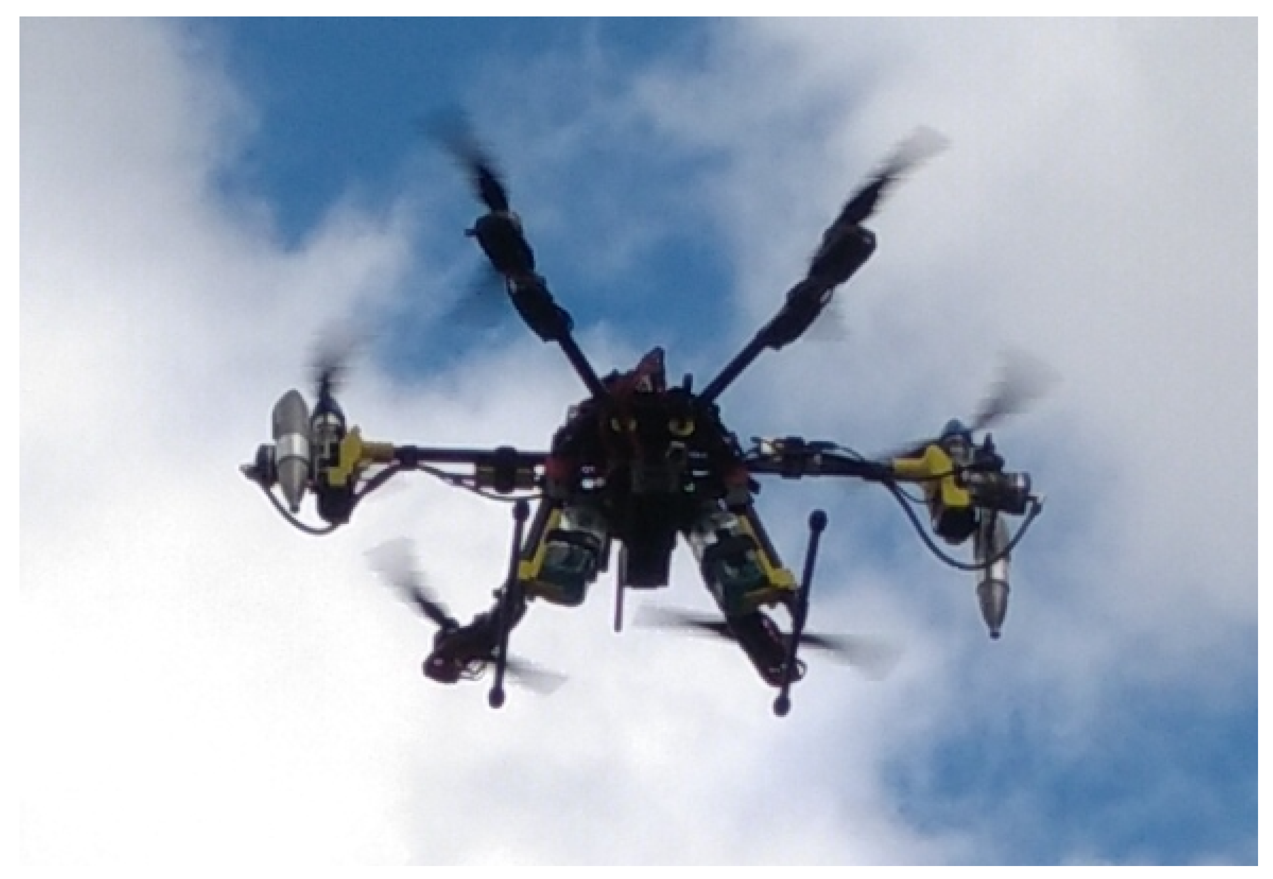
The prototype was also tested without a test stand.
Figure 23 shows that the prototype successfully flew with a 75:25 gas-to-electric thrust ratio. While it could hover, careful control was consistently required from the pilot. Thus, the prototype was unable to sustain long flight times during free flight due to challenges with control. This was likely because the system was configured for ideal operation with no wind, and future work includes refining the control system to ease the strain on the pilot.
8. Summary and Future Work
A gasoline–electric hybrid multirotor drone was designed, modeled, tested, and analyzed to determine how the addition of a gasoline system affects the flight time of an electric multirotor drone. The hybrid prototype exploits the advantages of electric and gasoline propulsion systems to achieve a long flight time. The fast-response electric motors provide stability to the prototype, while the gasoline propulsion system provides the majority of the lift force. Operating the prototype with 75% of the lift coming from the gas system and 25% of the lift coming from the electric system maximized its flight time, which was 50 min on a controlled test stand.
The simulation and the experimental results specified the optimal gas-to-electric thrust ratio, the fuel amount, and the battery capacity in which all the energy reserves were depleted simultaneously. This ratio can differ from one design to another based on the fuel tank size, battery capacity used, motors and engine types, and drone weight. However, each propulsion system should have sufficient thrust to execute its function fully.
With information from the optimal line, the proposed prototype can be reconfigured to enhance its flight performance and reduce energy consumption rates. Future work related to this study includes more detailed testing on engine performance, thrust distribution, and controller enhancement.


