Article

Structural and Aeroelastic Studies of Wing Model with Metal Additive Manufacturing for Transonic Wind Tunnel Test by NACA 0008 Example

1
Aeronautical Directorate, Japan Aerospace Exploration Agency (JAXA), Mitaka, Tokyo 181-0015, Japan
2
Department of Aeronautics and Astronautics, The University of Tokyo, Hongo, Tokyo 131-8656, Japan
3
Aeronautical Directorate, Japan Aerospace Exploration Agency (JAXA), Chofu, Tokyo 182-8522, Japan
*
Author to whom correspondence should be addressed.
Aerospace 2021, 8(8), 200; https://doi.org/10.3390/aerospace8080200
Submission received: 28 June 2021 / Revised: 22 July 2021 / Accepted: 23 July 2021 / Published: 25 July 2021
(This article belongs to the Special Issue Metal Additive Manufacturing for Aerospace Applications)

Abstract

:
Additive manufacturing (AM) technology has a potential to improve manufacturing costs and may help to achieve high-performance aerospace structures. One of the application candidates would be a wind tunnel wing model. A wing tunnel model requires sophisticated designs and precise fabrications for accurate experiments, which frequently increase manufacturing costs. A flutter wind tunnel testing, especially, requires a significant cost due to strict requirements in terms of structural and aeroelastic characteristics avoiding structural failures and producing a flutter within the wind tunnel test environment. The additive manufacturing technique may help to reduce the expensive testing cost and allows investigation of aeroelastic characteristics of new designs in aerospace structures as needed. In this paper, a metal wing model made with the additive manufacturing technique for a transonic flutter test is studied. Structural/aeroelastic characteristics of an additively manufactured wing model are evaluated numerically and experimentally. The transonic wind tunnel experiment demonstrated the feasibility of the metal AM-based wings in a transonic flutter wind tunnel testing showing the capability to provide reliable experimental data, which was consistent with numerical solutions.

1. Introduction

Flutter is a phenomenon involving fluid–structure interaction, which sometimes leads to critical aircraft incidents [1]. Therefore, aeroelastic stability (flutter) analysis plays an important role in the design of aircraft to ensure its safety. Since recent aircraft fly at a cruise speed in transonic regime, aeroelastic stability of aircraft in a transonic regime must be ensured for safety. Flutter characteristics can be evaluated by numerical analysis, and those analytical results are often verified by wind tunnel experiments with wing models. Those wing models must satisfy strict requirements in terms of structural and aeroelastic characteristics avoiding structural failure and producing flutter within the wind tunnel test environment in order to observe/evaluate aeroelastic characteristics. Due to the strict requirements, flutter wing models tend to have significant cost and limited numbers of observations. In particular, an aeroelastic system in a transonic regime involves shocks and corresponding flow separations on wing surfaces, which lead to non-linear phenomena such as the limit cycle oscillation [2] and the transonic dip [3]. Therefore, a wing model for a transonic flutter testing requires extra efforts and costs to satisfy experimental objectives.
With the advancement in AM technology, sophisticated structures that had been conceptual and difficult to realize are ready to be fabricated at low cost [4]. The AM technology has shown a potential to facilitate structural research and development [5]. Therefore, this technology may make it possible to create effective wing models for flutter wind tunnel testing while saving manufacturing costs [6]. With the potential improvement of manufacturing costs and performance of aerospace structures [4,7], AM technology has already been applied to actual aerospace vehicles [8,9]. Among the AM techniques, the powder bed fusion (PBF) process (e.g., direct metal laser sintering (DMLS), electron beam melting (EBM), selective laser melting (SLM), and selective laser sintering (SLS), etc.) are the popular fabrication techniques with compatibility to metal alloys offering practical stiffness and strength properties.
Although the AM technique is useful for constructing complicated structures, mechanical characteristics of structures and materials created with the AM technique are known to be susceptible to process variables involving the manufacturing process [10,11,12]. Therefore, a precise understanding of correlations between the process variables and properties of structures fabricated by AM is important. In addition, it is common to adopt a wing design assembling a uniform spar with multiple flanges and additional masses in a traditional wind tunnel testing to achieve required aeroelastic characteristics. On the other hand, the AM technique enables a development of wing models with sophisticated structures based on an unconventional design approach, which would provide structural and aerodynamic characteristics more suitable for the objective of the experiment [13].
In this paper, a metal wing model with the EBM technique for a transonic flutter test is studied. The objective of the paper is to demonstrate the feasibility and capability of the metal AM-based wings to provide reliable experimental data, which is consistent with numerical solutions, in a transonic flutter wind tunnel testing. To obtain the structural properties of AM-based metal structure with Ti6Al4V, a series of tensile experiments were performed. The manufacturing accuracy of the AM-based wing model was then investigated. Furthermore, a wing model for a transonic flutter wind tunnel experiment was designed and fabricated. The aeroelastic stability of the designed wing model was analyzed by numerical and experimental evaluation.

2. Structural Evaluation

In this section, a series of tensile experiments were performed to evaluate the structural properties of AM-based metal structure with Ti6Al4V powder. The manufacturing accuracy of AM-based wing model was then investigated based on a simple vibration test and observations of surface roughness.

2.1. Structural Evaluation of Metal Additive Manufacturing (AM) Structures

Tensile test specimens to evaluate structural characteristics of AM-based structures were fabricated based on EBM using ArcamQ20 (Arcam, Gothenburg, Sweden). Tensile tests with the specimens were performed for the evaluations of their tensile properties in accordance with Japanese Industrial Standards (JIS) Z2201 [14]. The geometry of specimens was a dumbbell shape (No. 5) with the gage length of 50 mm and the thickness of 4 mm. The main process variables are summarized in Table 1. The specimens were additively manufactured with Ti6Al4V powder. The tensile tests were performed with five specimens. A picture of the experimental setup is shown in Figure 1. The strain was measured using a 50-mm gage length extensometer (Instron Corp., Norwood, MA, USA). The crosshead speed was 1.0 mm/min.
Stress-strain curves of the tensile tests are shown in Figure 2. Good reproducibility was observed according to the results, demonstrating the capability of the metal additive manufacturing to provide enough accuracy in terms of structural properties with the constant process variables. Note that the result of Specimen 1 is from the second trial because the first test was aborted due to a loose grip of the crosshead. Tensile properties obtained by the experiments are summarized in Table 2. Properties of a common titanium material (Ti6Al4V Grade 5) [15] are also provided as a reference. Most values are averages of the five specimens, while the yield strength is an average of four specimens without the result of Specimen 1. The values in the parentheses are the standard deviations.

2.2. Structural Evaluation of A Metal AM Wing Model

To evaluate a quality of a wing model fabricated by EBM prior to design and build an actual flutter wind tunnel model, a thin tapered wing model was constructed as upper and lower surfaces were shell structures with the thickness of 0.90 mm. The wing model used for the evaluation is shown in Figure 3. With this configuration, the aeroelastic characteristics and stability can be controlled by the single variable (i.e., shell thickness). Since it was aimed to evaluate only the structural properties, not aerodynamic characteristics, a post-process for surface treatment was not performed for the wing model. The span was 189.57 mm, while the root and tip chords were 64.18 and 20.84 mm, respectively. The aspect ratio was 8.93. The sweep angle of the leading edge and the incident angle were 0°. The wing tip was closed with a 0.9-mm wall. The airfoil profile was NACA0010 [16]. The process variables and material used were the same as those for the tensile specimens. Poisson’s ratio was assumed to be 0.33. Note that Poisson’s ratio was assumed by referring to values reported in previous studies [17,18] since the value was not measured in the tensile tests.
A vibration test was carried out to obtain the natural frequency of the first bending mode for the wing model. The test result was compared with a solution of modal simulation obtained by MSC.Nastran (MSC Software Corp., Newport Beach, CA, USA) [19]. In the finite element analysis, a wing model was discretized into 2096 elements using triangular shell elements as shown in Figure 4. A constant thickness of 0.9 mm was given for each flat element. Since the wing model was constructed with a base, which could be installed in a measurement section of a wind tunnel, the base was tightly clamped in order to set the cantilevered boundary condition. The six degrees of freedom of nodes on the wing root were fixed in the finite element model. With the same boundary condition, a uniaxial accelerometer (PCB Piezotronics of North Caroline, Inc., Halifax, NC, USA) was installed at a 3 mm distance from the wing tip at mid-chord to measure the uniaxial acceleration. An impulsive load was applied on the tip, and the acceleration data was processed through a fast Fourier transform analyzer (Ono Sokki Co., Ltd.) using a signal conditioner (PCB Piezotronics of North Caroline, Inc.). The frequency resolution was 0.1 Hz. Table 3 compares the measured natural frequency and a solution of modal analysis from MSC.Nastran. The measured and simulated natural frequencies of the first bending mode were also in a good agreement with an error less than 1%. The result ensured that a hollow wing model could be accurately built by additive manufacturing with Ti6Al4V in terms of vibration characteristics (i.e., stiffness and mass distributions), which relates to characteristics of aeroelastic stability. On the other hand, aeroelastic performance is determined not only by the first bending mode but the other bending and torsional modes. However, the lower torsional and other bending modes were not evaluated since those measurements require a more sophisticated measurement system. Those characteristics were studied in the actual flutter wing model.
Furthermore, surface roughness of the metal wing model fabricated with the additive manufacturing without post-surface treatments was measured to decide if the post-processing was necessary. The values of surface roughness in the area of 2.0 mm × 2.0 mm were measured using a one-shot 3D measuring microscope (Keyence Corp., Osaka, Japan) as shown in Figure 5. Table 4 lists the measured results at different surface locations of the wing model. The average roughness was 46.4 μm, while the standard deviation was 16.95 μm. It was confirmed that post-surface treatments were necessary for an actual wind tunnel wing model since the surface was not smooth enough for a wind tunnel testing. Note that surface roughness on wing models for subsonic and transonic wind tunnel testing is required to be less than 10 μm in general [20,21].

3. Transonic Wind Tunnel Testing

Based on the evaluation results, a wing model for a transonic flutter wind tunnel experiment was designed and fabricated. The aeroelastic stability of the designed wing model was analyzed by numerical and experimental evaluation.

3.1. Wing Model Fabricated by Metal AM for Transonic Flutter Testing

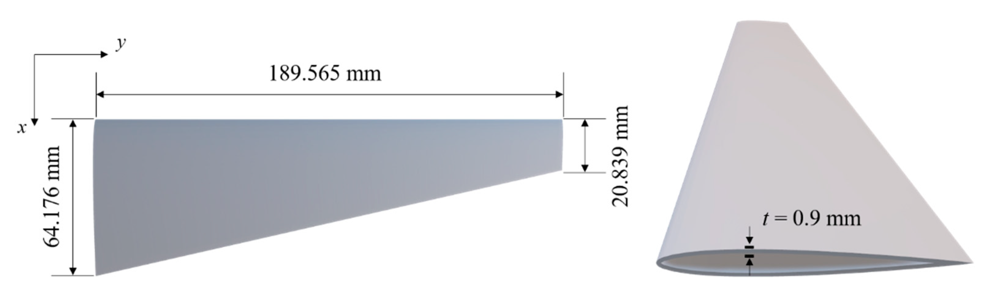
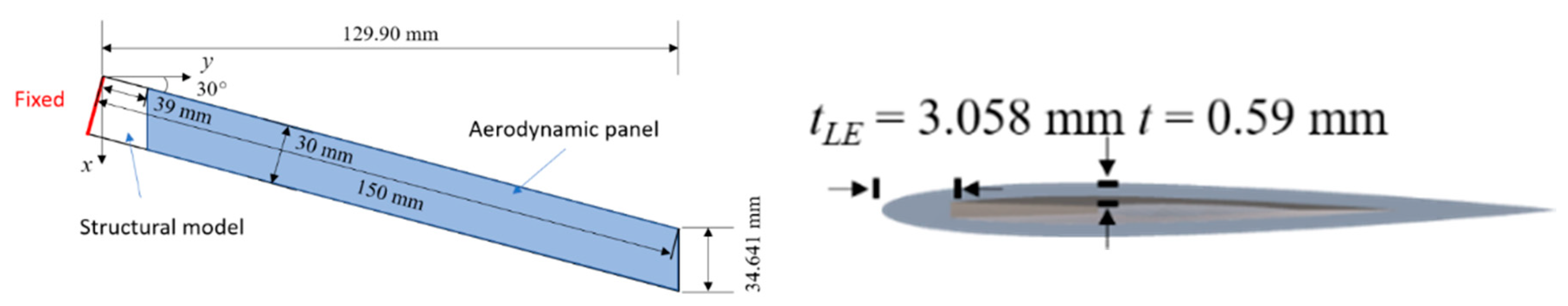
A wind tunnel wing model for a transonic flutter test was designed to investigate the flutter characteristics of a wing model fabricated by the metal AM technology. Numerical simulations were then performed to evaluate the structural and aeroelastic characteristics of the designed wing model. The designed thin rectangular wing model is shown in 
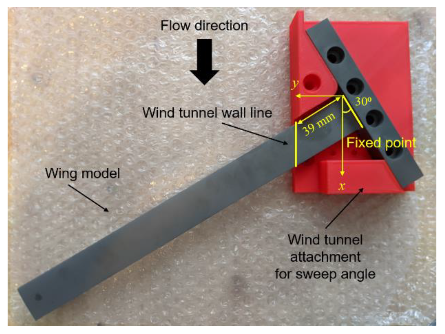
Figure 6. The aft portion of the wing was designed as shell structures with the thickness of 0.59 mm. The front section (up to about 3 mm from the leading-edge) was modeled as a solid structure. The wing root was integrated with a base for installation to a wing tunnel, which produced a sweep angle of 30° and an incident angle of 1°, with a holding jig as shown in Figure 7. Note that an aluminum jig was used in the actual experiment instead of the plastics. When the wing was installed in the wind tunnel, only the highlighted area in Figure 6, which was a 39-mm location from the root to the tip, was exposed in a flow. The flow was aligned to the x direction. In the AM process, the wing model was built by going from the base to the tip in the spanwise direction. The tip was then cut so that the tip was also aligned to the flow direction (i.e., the x direction). The span and chord lengths were 129.90 mm and 34.641 mm, respectively. The aspect ratio was 7.50. The process variables and material properties were the same as those for the tensile specimens. The wing model was fabricated by JAMPT Corp. (Miyagi, Japan).
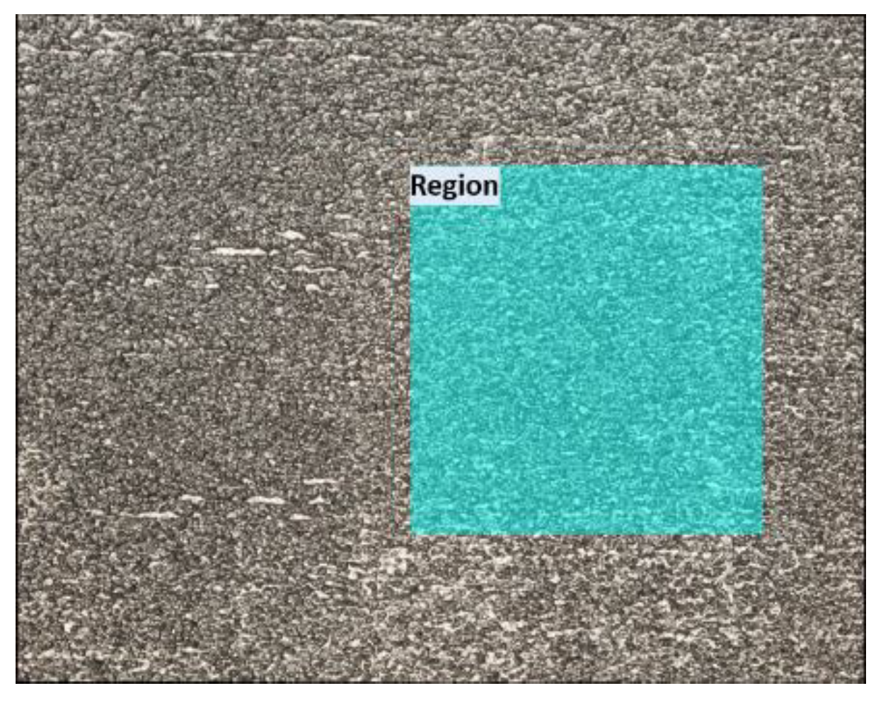
The geometry of the fabricated wing was measured by a digital caliper and the ATOS 3D scanner (GOM, Braunschweig, Germany). The average chord was 29.54 mm. The difference to the model was ±0.46 mm. In other words, the percent error to the model was almost less than 1.5%. A part of the geometrical error was attributed to the surface finish by mechanical metal polishing. Surface roughness of the flutter wing at locations 60 mm distant from the tip on the upper and lower surfaces were then measured using the one-shot 3D measuring microscope. The values of surface roughness were measured in the area of 2.0 mm × 2.0 mm (Sa) and on the lines of 2.0 mm (Ra) in the chordwise and spanwise directions. Table 5 summarizes the measurements. The averages of the roughness on the line profiles in the chordwise and spanwise directions were 0.9 μm and 0.8 μm for the upper and lower surfaces, while the standard deviations were 0.25 μm and 0.24 μm. The average roughness and standard deviation in the measured area were 1.1 μm and 0.11 μm. Therefore, the surfaces were smooth enough for a transonic flutter test.
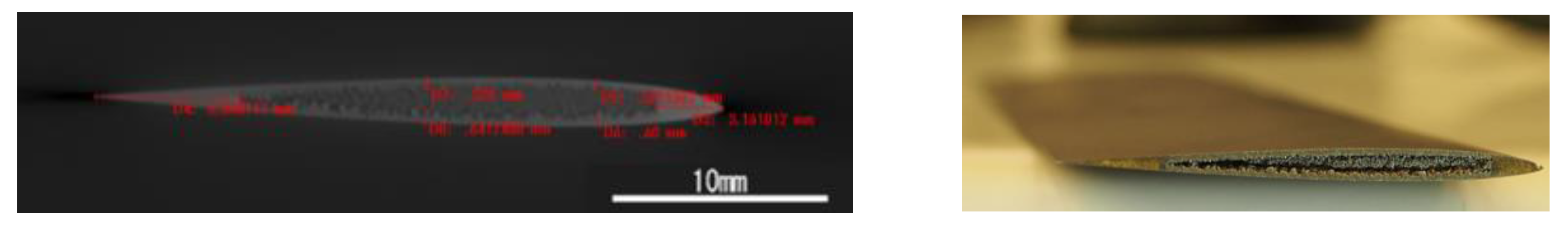
In addition, the internal geometry and the shell thickness were measured by an X-ray computer tomography scanner (TOSCANNER-32300μFPD by Toshiba IT and Control Systems Corp., Tokyo, Japan). The scanned cross-section is shown in Figure 8. The solid front section ended at a location 3.161 mm from the leading edge, and the average shell thickness was 0.5707 mm. Therefore, it was confirmed that the wing model was built reasonably accurately by the AM and the surface treatment. However, as shown in Figure 8, an imperfect removal of metal powder during the fabrication caused residual particles in the hollow of the wing. The effects of the residual particles were considered in the following analysis as these particles did not contribute to stiffness of the wing but increased mass.
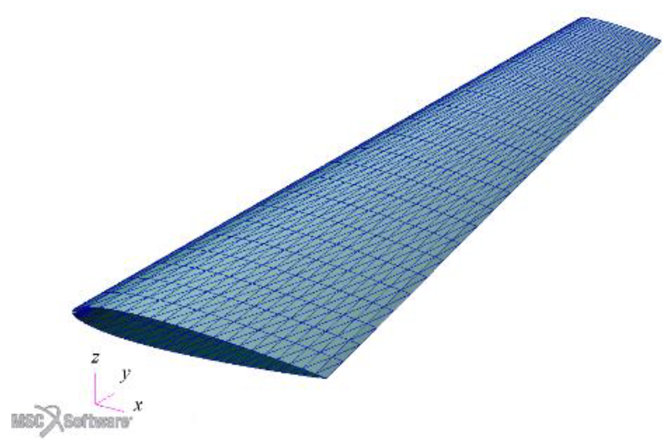
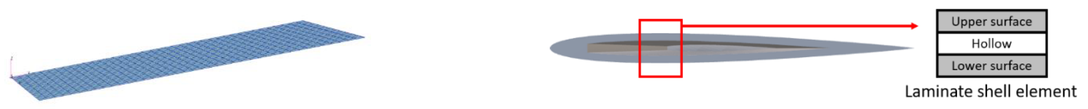
In order to precisely capture and evaluate the wing characteristics, a finite element model as shown in Figure 9 was constructed with 800 rectangular shell elements. Individual shell elements in the chordwise direction had constant thicknesses corresponding to NACA0008 profile. The thickness of a chordwise element was determined by calculating thicknesses of the airfoil at each nodal location and averaging the thicknesses of the adjacent nodes in each element. Also, elements in which the hollow section was included were modelled using a three-layered composite laminate element with the middle layer having zero stiffness (Young’s modulus = 0). The layer thickness of the upper and lower surfaces was 0.57 mm. Effects of the imperfect removal of metal powder were considered by assuming that metal powder with the half-density was filled in the hollow layer.
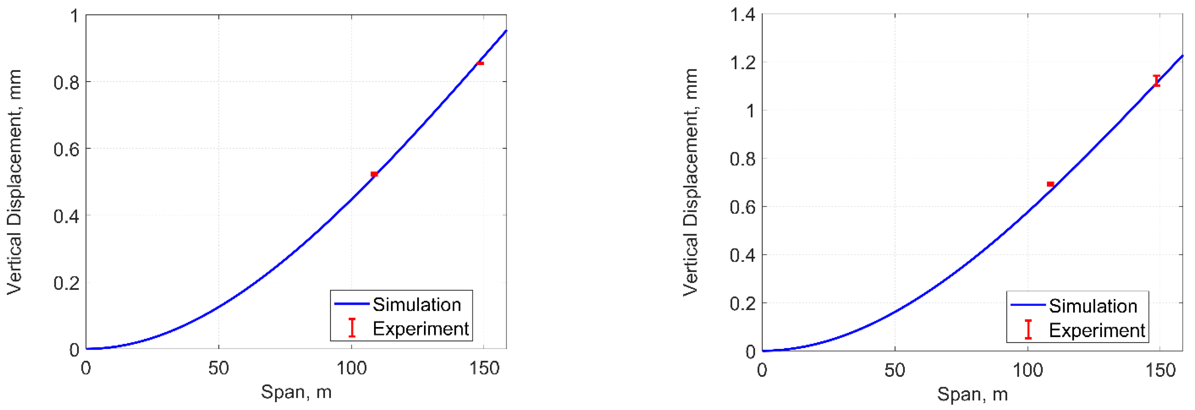
A static load test with the wing model was performed to evaluate its structural characteristics. The test results were compared with solutions of static structural simulations obtained by MSC.Nastran (MSC Software Corp., Newport Beach, CA, USA). Since the wing model was constructed with a base, that could be installed in a measurement section of a wind tunnel, the basement was tightly clamped in order to set the cantilevered boundary condition. All nodes on the wing root were fixed in the finite element model. A 0.7- or 0.9-N weight was installed on the tip of the wing at mid-chord. The mid-chord vertical displacements at 10, 50, and 100 mm from the tip were measured using a laser displacement sensor (Keyence Corp., Osaka, Japan), the resolution of which was 2 μm. Figure 10 shows the measured and simulated vertical displacements along the span with the different loads. Each measurement was obtained three times. The error bars showed that the measurements were consistent with minimal deviations. The results showed good agreements with errors of 0.14% and 2.56% at the most under 0.7 and 0.9 N loading.
A modal analysis was also performed to obtain the natural frequencies of the wing model with a cantilevered boundary condition. The ground vibration test (GVT) was also performed by installing the fabricated flutter wing model in the wind tunnel to evaluate natural frequencies of the wing. A frequency resolution of the GVT measurement was 0.15 Hz. Table 6 shows the simulated and measured natural frequencies of the lower modes. The differences between the solutions and the measurements with respect to the first and second out-of-plane bending modes were less than 4%. There were discrepancies between the solutions and the measurements in terms of the first torsion and the third out-of-plane bending modes due to the remaining metal powder in the hollow and the geometrical difference in the shell thickness. In future work, improvements on an AM method for a better geometrical accuracy and a removal of the internal powder residual will be considered.
A linear flutter analysis was then carried out to evaluate the aeroelastic stability of the designed wing by MSC.Nastran. In the simulation, the PK-method was used to predict aeroelastic instabilities. The unsteady aerodynamics was considered by the Doublet Lattice Method (DLM). Aerodynamic panels were constructed only on the region exposed in a flow as shown in Figure 6. 
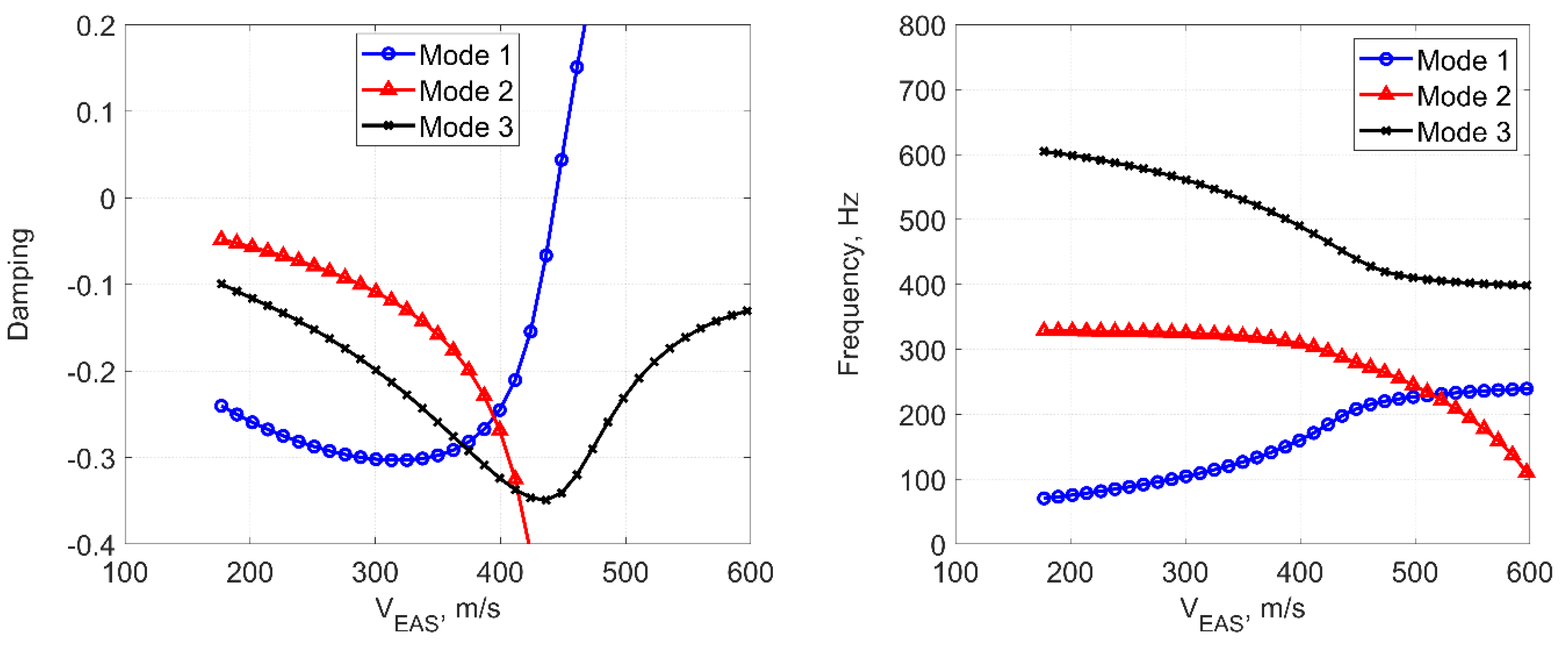
Figure 11 shows the V-g and V-f plots obtained from the analysis with the total temperature P0 = 288.15 K, the total pressure P0 = 400 kPa, the reference air density ρref = 1.225 kg/m3, and mach number M = 0.9. According to the result, it was predicted that the wing model would encounter aeroelastic instability at the equivalent airspeed VEAS = 443.91 m/s with the flutter frequency ωf = 203.94 Hz.

3.2. Transonic Flutter Testing

A transonic flutter wind tunnel test with the additively manufactured wing model was performed to evaluate its aeroelastic characteristics. In addition, the test result was compared with the analysis. The wind tunnel test was conducted in the Transonic Flutter Wind Tunnel at the Japan Aerospace Exploration Agency (JAXA). The wind tunnel was a blow-down type and had a 0.6 m × 0.6 m closed test section. 
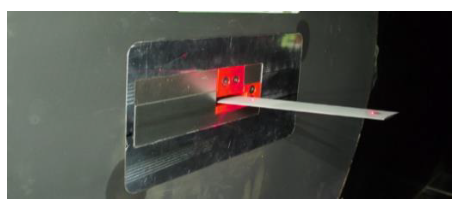
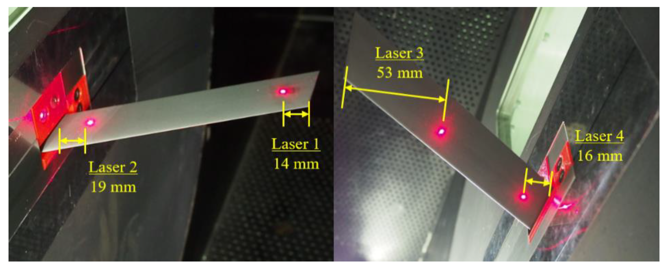
Figure 12 shows the test environment for the wind tunnel experiment. In the experiment, aeroelastic vertical deformations of the wing model at four locations on the upper and lower surfaces around the mid-chord as shown in Figure 13 were measured using laser displacement sensors (Keyence Corp., Osaka, Japan), which had a minimum resolution of 2 μm. Two measurements were at 14 mm and 53 mm from the wing tip on the upper and lower surfaces, while the others were at 19 mm and 16 mm from the wall on the upper and lower surfaces. In addition, strain gages (rosettes) were installed on the wing root on the upper and lower surfaces to measure strains related to bending and torsional deformations. Note that the GVT for the wing model was conducted using the displacement measurements obtained by the laser sensors. The total pressure P0 was increased until an aeroelastic instability was observed with a constant mach number M. 
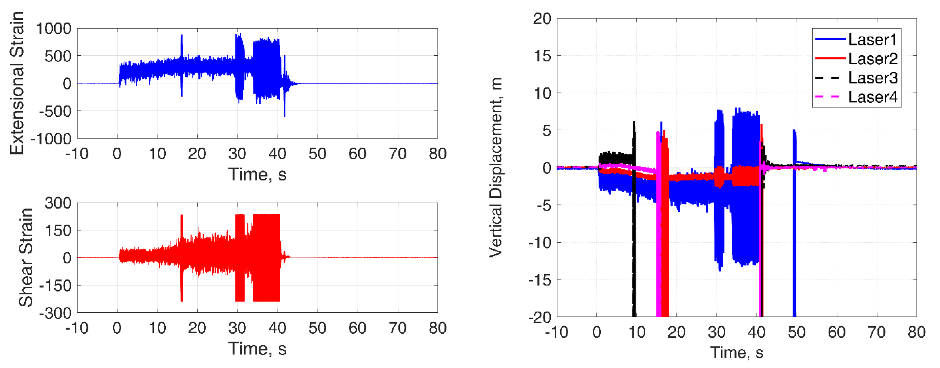
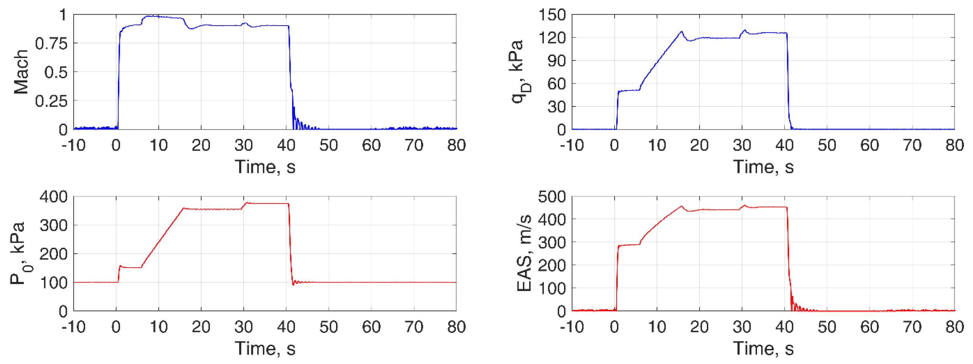
Figure 14 shows the outputs of the strain gages and the laser displacement sensors during the aeroelastic instability in the flutter test. Also, the total pressure and mach number with the corresponding dynamic pressure qD and equivalent speed VEAS are shown in Figure 15. The tensile strain output indicated that the wing experienced a limit cycle oscillation (LCO) although the shear strain output was saturated during the aeroelastic instability. The LCO was observed in the outputs of the laser sensors around 35–40 s. The flutter frequency ωf was 205.60 Hz. The flutter occurred at qD = 125.80 kPa and VEAS = 453.19 m/s with M = 0.90 and P0 = 374.21 kPa. A solution of a flutter analysis with the same aerodynamic condition gave qD = 120.29 kPa and VEAS = 443.13 m/s, and ωf = 203.84 Hz, whose differences to the experimental results were 4.58%, 2.27%, and 0.86%. Therefore, it is concluded that the proposed methodology to obtain transonic flutter characteristics using the flutter wing model fabricated with the AM method could provide appropriate results.
Key characteristics required to a flutter wing model for a transonic wind tunnel testing are (1) flutter occurs in a range of aerodynamic condition, in which one wants to evaluate and an available wind tunnel can realize, (2) experimental data with respect to aeroelastic characteristics can be obtained without structural failures (at least the model should withstand the loads until the completion of the test). It was concerned that structural failure might occur during the transonic flutter testing based on local strength reductions due to void residuals attributed to the metal AM process. However, a visual inspection and a GVT conducted after the wind tunnel testing have proven that the wing model had enough strength to withstand a transonic flutter testing and the capability to provide reliable and informative experimental data without any cracks and deteriorations in vibration characteristics. It was confirmed that reliable experimental results consistent with the numerical predictions by MSC.Nastran could be obtained with the proposed methodology.

4. Conclusions

This paper studied a metal wing model with the EBM technique for the flutter test. Structural/aeroelastic characteristics and geometrical accuracy of an additively manufactured wing model were evaluated numerically and experimentally. The wing, whose aeroelastic characteristics were controlled by the shell thickness, was modeled based on the simple design approach as a shell structure and fabricated by the metal AM technique. The numerical and experimental results can be summarized as follows:
  • The metal AM technique could provide enough accuracy to fabricate the designed structures with good reproducibility under constant printing conditions.
  • The wing model fabricated by the EBM technique with Ti6A4V powder could achieve the designed elastic and vibration characteristics, appropriate for wind tunnel testing. However, additional surface treatment was needed to achieve a reasonable surface roughness level for wind tunnel testing.
  • The transonic wind tunnel experiment demonstrated the feasibility of the metal AM-based wing in a transonic flutter wind tunnel test showing the capability to provide reliable experimental data, which was consistent with the numerical solutions by MSC.Nastran.
Although the wing design used in this study can control its aeroelastic characteristics by a single parameter (i.e., shell thickness), the model requires special attention to metal powder residuals in the structure for a precise realization of the designed characteristics. Therefore, a fabrication method minimizing the power residual will be considered in future work. Also, evaluations of the feasibility for applications of AM-based wings in transonic flutter testing should not be limited to a single flutter point. A further investigation with multiple points on flutter boundaries will be performed to fully explore the capabilities. A flutter in the transonic regime exhibits complicated phenomena such as transonic dip. An investigation of such phenomena with AM-based wing models will also be studied in comparison with numerical non-linear simulations. Moreover, a design independently controlling bending and torsional stiffnesses, which are related to the aeroelastic stability, will be considered so that more design freedom in a transonic flutter wind tunnel model can be realized taking advantage of the metal AM technique.

Author Contributions

Conceptualization, N.T., K.S. and K.N.; Data curation, N.T.; Funding acquisition, N.T.; Investigation, N.T.; Methodology, N.T.; Software, N.T.; Supervision, K.S., H.A. and K.N.; Writing—original draft, N.T.; Writing—review and editing, K.S., H.A. and K.N. All authors have read and agreed to the published version of the manuscript.

Funding

Part of the research was conducted under the financial support of Grant-in-Aid for Scientific Research (19K15216) by Japan Society for the Promotion of Science.

Acknowledgments

The authors would like to acknowledge JAMPT Corp. for fabrications of the AM-based specimens and wing models.

Conflicts of Interest

The authors declare no conflict of interest.

References

  1. Kehoe, M.W. A Historical Overview of Flight Flutter Testing; NASA TM-4720; NASA: Edwards, CA, USA, 1995.
  2. Dowell, E.H.; Thomas, J.P.; Hall, K.C. Transonic Limit Cycle Oscillation Analysis Using Reduced Order Aerodynamic Models. J. Fluid. Struct. 2004, 19, 17–27. [Google Scholar] [CrossRef]
  3. Isogai, K. On the Transonic-Dip Mechanism of Flutter of a Sweptback Wing. AIAA J. 1979, 17, 793–795. [Google Scholar] [CrossRef]
  4. Berger, J.B.; Wadley, H.N.G.; McMeeking, R.M. Mechanical Metamaterials at the Theoretical Limit of Isotropic Elastic Stiffness. Nature 2017, 543, 533–537. [Google Scholar] [CrossRef] [PubMed] [Green Version]
  5. Goh, G.D.; Agarwala, S.; Goh, G.L.; Dikshit, V.; Sing, S.L.; Yeong, W.Y. Additive Manufacturing in Unmanned Aerial Vehicles (UAVs): Challenges and Potential. Aerosp. Sci. Technol. 2017, 63, 140–151. [Google Scholar] [CrossRef]
  6. Moioli, M.; Reinbold, C.; Sørensen, K.; Breitsamter, C. Investigation of Additively Manufactured Wind Tunnel Models with Integrated Pressure Taps for Vortex Flow Analysis. Aerospace 2019, 6, 113. [Google Scholar] [CrossRef] [Green Version]
  7. Bauer, J.; Meza, L.R.; Schaedler, T.A.; Schwaiger, R.; Zheng, X.; Valdevit, L. Nanolattices: An Emerging Class of Mechanical Metamaterials. Adv. Mater. 2017, 29, 1701850. [Google Scholar] [CrossRef] [PubMed]
  8. Banfield, C.; Kidd, J.; Jacob, J.D. Design and Development of a 3d Printed Unmanned Aerial Vehicle. In Proceedings of the 54th AIAA Aerospace Sciences Meeting, San Diego, CA, USA, 4–8 January 2016. [Google Scholar]
  9. McSwain, R.G.; Geuther, S.C.; Howland, G.; Patterson, M.D.; Whiteside, S.K.; North, D.D.; Glaab, L.J.; Rhew, R.D. An Experimental Approach to a Rapid Propulsion and Aeronautics Concepts Testbed; NASA TM-2020-220437; NASA: Hampton, VA, USA, 2020.
  10. Rodriguez, J.; Thomas, J.; Renaud, J. Maximizing the Strength of Fused-Deposition ABS Plastic Parts. In Proceedings of the 10th Solid Freeform Fabrication Symposium (SFF), Austin, TX, USA, 9–11 August 1999. [Google Scholar]
  11. Adelnia, R.; Daneshmand, S.; Aghanajafi, S. Production of Wind Tunnel Testing Models with Use of Rapid Prototyping Methods. In Proceedings of the 6th WSEAS International Conference on Robotics, Control and Manufacturing Technology, Hangzhou, China, 16–18 April 2006. [Google Scholar]
  12. Cuan-Urquizo, E.; Barocio, E.; Tejada-Ortigoza, V.; Pipes, R.B.; Rodriguez, C.A.; Roman-Flores, A. Characterization of the Mechanical Properties of FFF Structures and Materials: A Review on the Experimental, Computational and Theoretical Approaches. Materials 2019, 12, 895. [Google Scholar] [CrossRef] [PubMed] [Green Version]
  13. Zhu, W. Models for Wind Tunnel Tests Based on Additive Manufacturing Technology. Prog. Aeosp. Sci. 2019, 110, 100541. [Google Scholar] [CrossRef]
  14. Association, J.S. Test Pieces for Tensile Test for Metalic Materials, JIS Z 2201; Japanese Standards Association: Tokyo, Japan, 2004; p. 227. [Google Scholar]
  15. ASM Aerospace Specification Metals, Inc., Titanium Ti-6Al-4V (Grade 5), Annealed. Available online: Asm.matweb.com (accessed on 22 June 2021).
  16. Polentz, P.P. Comparison of the Aerodynamic Characteristics of the Naca 0010 and 0010-64 Airfoil Sections at High Subsonic Mach Numbers; NACA RM-A9G19; NASA: Moffett Field, CA, USA, 1949.
  17. Wang, X.; Gong, X.; Chou, K. Scanning Speed Effect on Mechanical Properties of Ti-6Al-4V Alloy Processed by Electron Beam Additive Manufacturing. Procedia Manuf. 2015, 1, 287–295. [Google Scholar] [CrossRef] [Green Version]
  18. Tiferet, E.; Ganor, M.; Zolotaryov, D.; Garkun, A.; Hadjadj, A.; Chonin, M.; Ganor, Y.; Noiman, D.; Halevy, I.; Tevet, O.; et al. Mapping the Tray of Electron Beam Melting of Ti-6Al-4V: Properties and Microstructure. Materials 2019, 12, 1470. [Google Scholar] [CrossRef] [PubMed] [Green Version]
  19. MSC Software Corp. MSC.Nastran 2004 Reference Manual; MSC Software Corp.: Newport Beach, CA, USA, 2004. [Google Scholar]
  20. Adelnia, R.; Aghanajafi, S.; Daneshmand, S.; Toosi, K. Evaluation of Surface Finish Affect on Aerodynamic Coefficients of Wind Tunnel Testing Models. In Proceedings of the 4th WSEAS International Conference on Fluid Mechanics and Aerodynamics, Elounda, Greece, 21–23 August 2006. [Google Scholar]
  21. Tsushima, N.; Tamayama, M.; Arizono, H.; Makihara, K. Geometrically Nonlinear Aeroelastic Characteristics of Highly Flexible Wing Fabricated by Additive Manufacturing. Aerosp. Sci. Technol. 2021, 117, 106923. [Google Scholar] [CrossRef]
Figure 1. Tensile test setup with the additively manufactured structure using Ti6Al4V.
Aerospace 08 00200 g001
Figure 2. Stress-strain curves the additively manufactured structures using Ti6Al4V.
Aerospace 08 00200 g002
Figure 3. Planform (left) and cross section at root (right) of the wing model.
Aerospace 08 00200 g003
Figure 4. Finite element model of the wing.
Aerospace 08 00200 g004
Figure 5. A picture of the upper wing surface in the vicinity of the root.
Aerospace 08 00200 g005
Figure 6. Planform (left) and cross section at root (right) of the flutter wing model.
Aerospace 08 00200 g006
Figure 7. A picture of the flutter model in the vicinity of the root.
Aerospace 08 00200 g007
Figure 8. CT scan (left) and picture (right) of the cross-section of the flutter wing.
Aerospace 08 00200 g008
Figure 9. Finite element model (left) and cross-section description of a hollow element (right).
Aerospace 08 00200 g009
Figure 10. Vertical displacements along the span from the experiment and simulation under the tip load of 0.7 N (left) and 0.9 N (right).
Aerospace 08 00200 g010
Figure 11. V−g (left) and V−f (right) plots with M = 0.9 and P0 = 400 kPa.
Aerospace 08 00200 g011
Figure 12. Wind tunnel test setup.
Aerospace 08 00200 g012
Figure 13. Measurement locations of the laser displacement sensors.
Aerospace 08 00200 g013
Figure 14. Outputs of the strain gages and the laser displacement sensors.
Aerospace 08 00200 g014
Figure 15. Aerodynamic conditions during the transonic flutter testing.
Aerospace 08 00200 g015
Table 1. Process variables.
PowderLayer Height, mmSpeed Function (SF)
Ti6Al4V0.0820
Table 2. Tensile properties of AM-based structures with Ti6Al4V.
PowderYoung’s Modulus, GPaYield Strength, MPaUltimate Tensile Strength, MPaElongation, %Density, g/cm3
Ti6Al4V (reference)113.8880950144.43
Ti6Al4V (powder)104.87 (2.9850)867.21 (6.6155)937.56 (5.0590)9.2627 (0.52993)4.3730 (0.0040139)
Table 3. Natural frequencies of the wing obtained from the test and simulation.
ResultNatural Frequency, Hz
Simulation164.7
Experiment163.5
Table 4. Surface roughness of the wing model at different locations.
Inner Upper Surface Sa, µmOuter Upper Surface Sa, µmInner Lower Surface Sa, µmOuter Lower Surface Sa, µm
22.647.254.061.8
Table 5. Surface roughness of the flutter wing model at different locations.
Upper Surface Sa, µmUpper Surface Ra (Chordwise), µmUpper Surface Ra (Spanwise), µmLower Surface Sa, µmLower Surface Ra (Chordwise), µmLower Surface Ra (Spanwise), µm
1.21.10.71.01.00.7
Table 6. Lower natural frequencies of the flutter wing with respect to bending and torsional modes.
Mode ID.ModeSimulation, HzGVT, Hz *
11st out-of-plane bending53.0553.7
22nd out-of-plane bending329.19318.4
31st torsion615.38700.5
41st edgewise bending762.29--
53rd out-of-plane bending916.74859.8
* The resolution of the measurement was 0.15 Hz.
Publisher’s Note: MDPI stays neutral with regard to jurisdictional claims in published maps and institutional affiliations.

