1. Introduction
The start of the New Space paradigm has changed the development philosophy of the worldwide space-engineering field. New Space refers to the recent commercialization of the space sector, which is mainly led by private industries, rather than government-funded organizations. These industries are driving a better, faster, cheaper, and lighter space-development paradigm [
1,
2,
3,
4]. One of the major accelerators of the New Space paradigm is the emergence of small satellite constellations. The large-volume production of small satellites, based on a standardized satellite platform and commercially available on-board hardware, has reduced the development cost and schedule. In addition, the total launch cost can be reduced as multiple small satellites are launched together. These advantages make the small-satellite platform attractive for various challenging missions that require high temporal system performance, e.g., real-time remote sensing, global internet services, and high-speed communications [
4].
All satellites undergo various dynamic loads during the launch phase. These loads involve steady-state acceleration caused by the engine thrust, sinusoidal vibration caused by the engine cutoff, and a self-excited vibration, called the pogo effect, from the combustion instability of the launcher. Random vibrations are caused by the noise of the thrust, and mechanical shock is induced by the separation of the launcher stages and spacecraft. Because these dynamic loads are extremely severe and complex, they are one of the major factors that cause satellites and components to malfunction [
5]. Therefore, a proper structural design is essential to ensure the structural safety of the satellite in the launch environment.
Two approaches are used to enhance the structural safety of satellites during the design phase. One traditional approach is to design the spacecraft structure such that it has sufficient strength and stiffness to endure mechanical loading. However, this approach faces the technical issue on limitation in minimizing the mass and volume of the satellite, especially in small satellites with design limitations of their volume and mass. These factors are related to the available number of satellites that can be launched within the lift capability of the launcher and, therefore, directly lead to an increase in launch costs. The other method involves reducing the launch loads transmitted to the satellite by applying a whole-spacecraft vibration isolator (WSVI). The WSVI is achieved by implementing a low-stiffness and high-damping capability, compared to the conventional concept, which is rigidly mounted between the satellite and launch adaptor. This makes it possible to effectively reduce the mass and volume of the satellite by minimizing the design load of vibration-sensitive components. In addition, it can contribute to reducing the satellite’s development cost and schedule by optimizing the conventional verification process, which accounts for a large portion of the time and cost of satellite-development programs. In addition, the on-ground test process can be optimized, e.g., simplifying and skipping the test phases of the subsystem-level verification. For example, verification can be performed at a higher system level of the integrated test because using the WSVI greatly reduces the potential technical risks to the vibration-sensitive components at the subsystem level. Another possible test schedule mitigation might also be expected on the notching process in the launch-vibration tests because creating a proper notched input level takes a large portion of the time. These potential advantages of WSVIs are attractive for the New Space based development trend to achieve the goal of cost-effective small satellite development.
Several previous studies have been conducted to realize whole-spacecraft vibration isolators. Johnson et al. [
6] proposed WSVI systems called SoftRide UniFlex and SoftRide MultiFlex to realize launch-vibration isolation for the MINOTAUR/JAWSAT program. SoftRide UniFlex consisted of a titanium flexure and a viscoelastic material to reduce the dynamic loads acting on the satellite along the launcher axial direction. To isolate both axial and lateral excitations from the launcher, SoftRide MultiFlex consisted of a pair of UniFlex isolators integrated with each other through a central post. The vibration in the launcher axial direction was isolated in the same manner as the UniFlex. Isolation in the lateral directions was achieved by vibrational-energy dissipation from the shear deformation of the constrained layers, as the dynamic bending of the flexure occurred. To enhance the performance of SoftRide MultiFlex, SoftRide OmniFlex was developed by Johal et al. [
7]. The major difference from the previous version was that the constrained layer was installed at the sides of the titanium flexure. This enabled the isolator to be more compact in volume, as well as enhancing the damping capability. Jun et al. [
8] proposed an isolation system using two serially connected flexure elements and a shear damping unit laminated with a metal plate and viscoelastic material. Isolation in the axial and lateral directions was achieved by the bending behavior of the titanium flexure and the shearing behavior of the damping unit, respectively. Mastroddi et al. [
9] proposed a multi-frequency dynamic absorber using a two-spring mechanism arranged in each axial and lateral direction. These mechanisms are connected with the oscillating mass for tuning the specific target frequency for the spacecraft during the launch phase. Rittweger et al. [
10] proposed an active payload adaptor compliant with the Ariane 5 space-launch vehicle, which was able to reduce the interface loads to the payload in the 5–100 Hz low frequency domain by more than a factor of four.
In actualizing a novel high damping three-axis passive launch vibration isolation for small satellite, we focused on the following two technical aspects. One is using the superelasticity of the shape memory alloy (SMA) material, and the other is applying multilayered thin plates with viscous lamina tapes to the SMA blades. The superelasticity is a unique characteristic of SMA material occurred by stress-induced phase transformation from the austenite to the martensite phase when the material is at above austenite finish temperature. It can be deformed considerably without being plastically deformed and recovers its original shape upon unloading. This makes it possible to ensure the structural safety of a satellite under the launch environment, even if the satellite is supported by a low-stiffness SMA application. In addition, this characteristic is associated with large hysteretic damping, owing to the phase transformation [
11].
The effectiveness of using superelastic SMA for vibration isolation in space applications has been demonstrated in several previous studies [
12,
13]. For example, Kwon et al. [
12] proposed a superelastic SMA gear wheel that applied a two-axis gimbal-type X-band antenna to enhance the micro-jitter isolation capability without undergoing plastic deformation under excessive loading conditions. Kwon et al. [
13] also proposed a blade-type cooler vibration isolator using a superelastic SMA material as a technical solution over ordinary titanium material. Then, the effectiveness of the superelastic SMA blade design was experimentally assessed and compared with that of an isolator made of titanium.
If the superelastic SMA is applied to the WSVI, it is possible to ensure the structural safety of the satellite in a launch environment, while implementing a low-stiffness isolator. However, the SMA exhibits effective hysteretic damping only when the stress exceeds the critical point at which a phase transformation occurs. This means that an isolator with SMA material may exhibit insufficient damping performance, if the deformation is not sufficiently large. Therefore, in this study, we proposed to apply multilayered thin plates with viscous lamina tapes to maximize the damping capability, even under a relatively small deformation.
The effectiveness of viscoelastic multilayered thin plates in enhancing the damping capability has been investigated in many studies [
14,
15,
16,
17]. Minesugi et al. [
14] proposed damping mechanisms of polyimide tape with a viscous lamina to reduce the vibration transmitted to the battery panel of the MUSES-A satellite. The experimental results showed that a five times higher damping performance was obtained when viscous lamina was applied, as compared to that without the lamina. Bhattarai et al. [
15] proposed a highly damped deployable solar-panel module using a multilayered stiffener with viscoelastic acrylic tape. The design effectiveness of the solar-panel module was validated through a launch-vibration test.
Park et al. [
16] proposed a high damping printed circuit board (PCB) with multilayered viscoelastic acrylic tapes for use in wedge lock applications. This PCB concept was effective in increasing the fatigue life of electronic packages, owing to the highly increased damping capability, as well as minimizing the volume and mass of the electronics. Stoudt et al. [
17] hypothesized that using nanoscale multilayer coatings could significantly increase the fatigue durability. To confirm this hypothesis, cyclic-loading fatigue tests were performed with Cu-coated films and different surface treatments, including a nanoscale Cu-Ni multilayer. The results of the fatigue tests showed that the Cu-Ni multilayer film had a fatigue life more than six times greater than that of the other general films under cyclic-loading conditions because the slip between each layer acted as a stress-energy–dissipation mechanism.
In this study, the basic characteristics of the passive WSVI with various number of interlaminated layers on the superplastic SMA blade, designed for vibration isolation of 40 kg class satellite, were obtained through static load tests. In addition, to validate the effectiveness of the design in terms of the launch-load attenuation, sine and random vibration tests were performed using a mass-simulating dummy satellite. These test results demonstrated that the proposed WSVI is effective for achieving a novel design goal of both superelastic and high damping capability.
2. WSVI Design Description
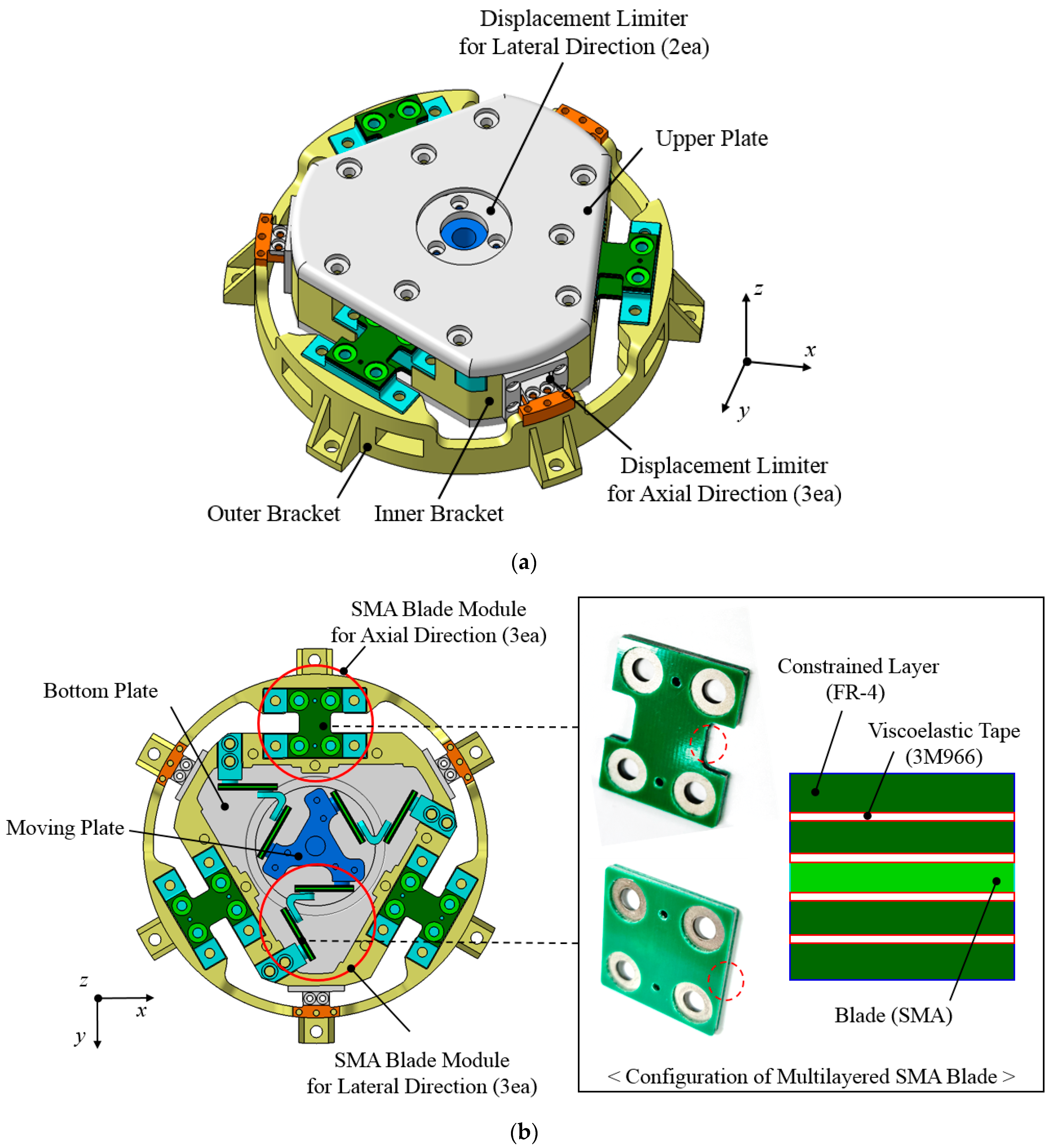
Figure 1a,b show isometric and internal views of the proposed WSVI. This WSVI was developed to reduce the launch loads above the range of the 28 Hz target cut-off frequency for a 40 kg class satellite. The design strategy of the isolator involves implementing a high damping capability by applying a superelastic SMA blade with a multilayered thin plate with viscous lamina tapes. The SMA material can be applied because it provides superelastic characteristics, high damping capability, and fatigue durability, compared to ordinary metal materials [
12]. Superelastic behavior is known to have complete reversibility for strains of up to 10–12% without being plastically deformed, which is a very uncommon feature in ordinary metal materials [
11]. Therefore, the SMA blade makes it possible to ensure the structural safety of the low stiffness blade of the isolator under the launch environment.
In addition, multilayered thin metal plates with viscous lamina tapes were utilized to increase the damping capability, which also helped distribute the stress release acting on the thin SMA blade. The proposed WSVI is mainly composed of SMA blade modules to achieve the required target cut-off frequency in the axial and lateral directions, a moving plate, upper and bottom plates, inner and outer brackets, and displacement limiters to limit the movement of the blades to within their allowable deflection range. The stiffness of the vibration isolator for each axis is significantly governed by the SMA blade modules. To achieve the required isolator stiffness, the SMA blade modules for the axial direction are connected between the inner and outer brackets at 120° intervals. The SMA blade modules for the lateral direction are arranged between the moving plate and inner bracket, in the same manner as those of the axial direction. The blade is made of superplastic SMA, and it provides a mechanical interface to attach viscoelastic adhesive tapes with thin constrained layers made of FR-4 material. Two constrained layers were applied to each side of the SMA blade. The physical contact between the constrained layers and adhesive tapes reduces the resultant stress acting on the SMA blade because the viscoelasticity resists additional deformations of the SMA blade. Furthermore, each boundary layer between the adhesive tapes and constrained layers experiences shear deformation when the multilayered SMA blade is deformed. This design contributes to the excellent damping performance and enhanced structural safety of the SMA blades. To limit the deformation of the blades within the allowable range of ±5 mm, displacement limiters made of high damping plastic material of Delrin [
18], with space heritages are included on the design, which is helpful to dissipate and mitigate launch vibration loads when slip and contact occur between the plastic and plastic materials. The mechanical properties of the SMA materials are summarized in
Table 1 [
12]. The viscoelastic tape used in this study was 3M966 double-sided acrylic tape (3M) [
19], as listed in
Table 2.
A static load test was performed at room temperature to evaluate the basic characteristics of the proposed WSVI. Two WSVI cases with different SMA blade thicknesses (1) 0.8 mm and (2) 1.5 mm were used in this test.
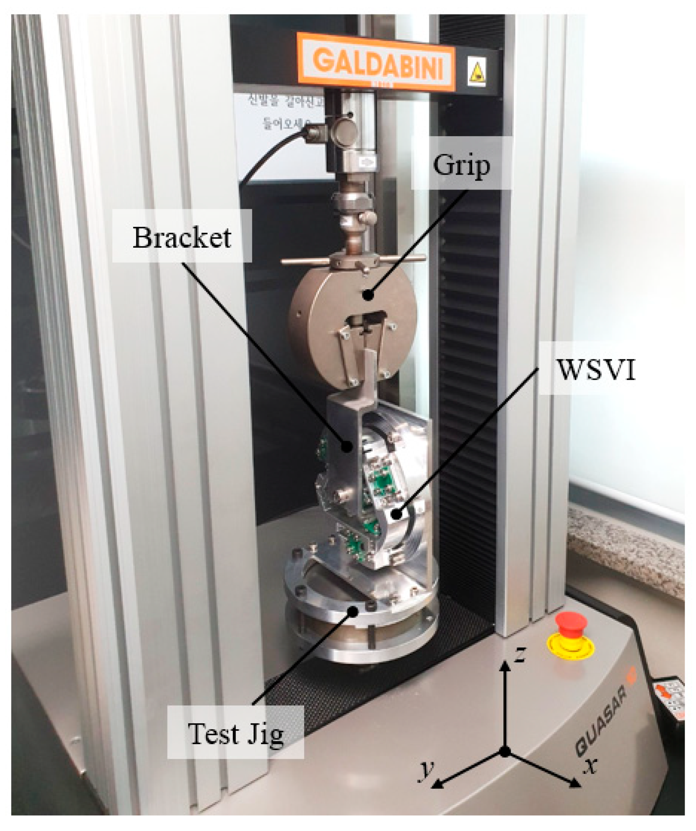
Figure 2 shows an example of a static load test setup for the lateral axis. The WSVI was connected to the load cell using a grip and a connector, which was mounted on the upper side of the static testing machine. In addition, the Delrin parts of the WSVI were intentionally removed to check the internal status of the blades during the test. Repeated translational loadings of three cycles in the positive and negative directions were applied to the WSVI in each axis to measure its basic characteristics. The translational displacements acting on the SMA blade modules in Cases (1) and (2) are ±4 mm and ±3 mm, respectively, with a velocity of 2 mm/min. The corresponding displacement ranges are the estimated maximum displacements derived from the launch vibration analysis.
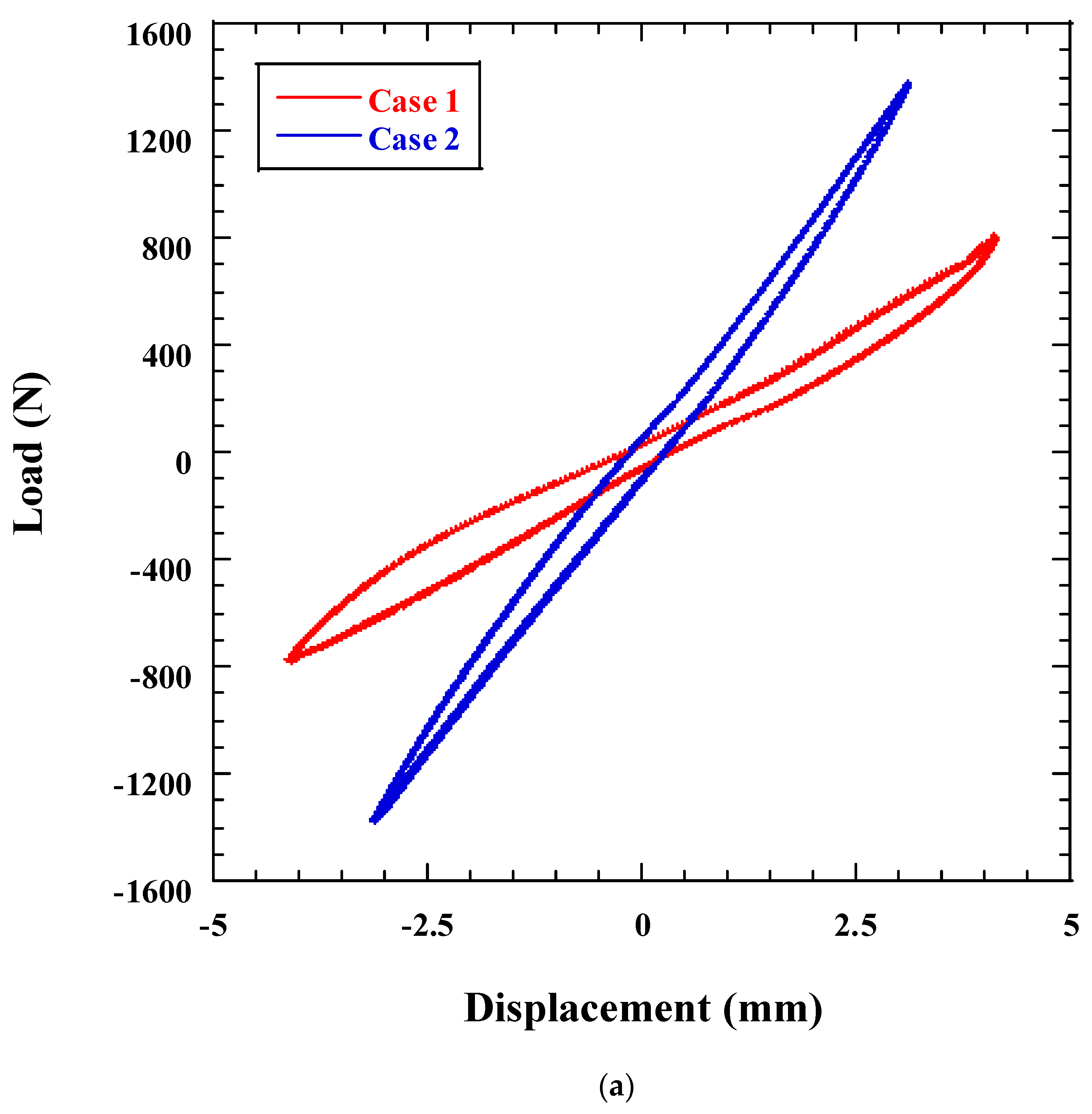
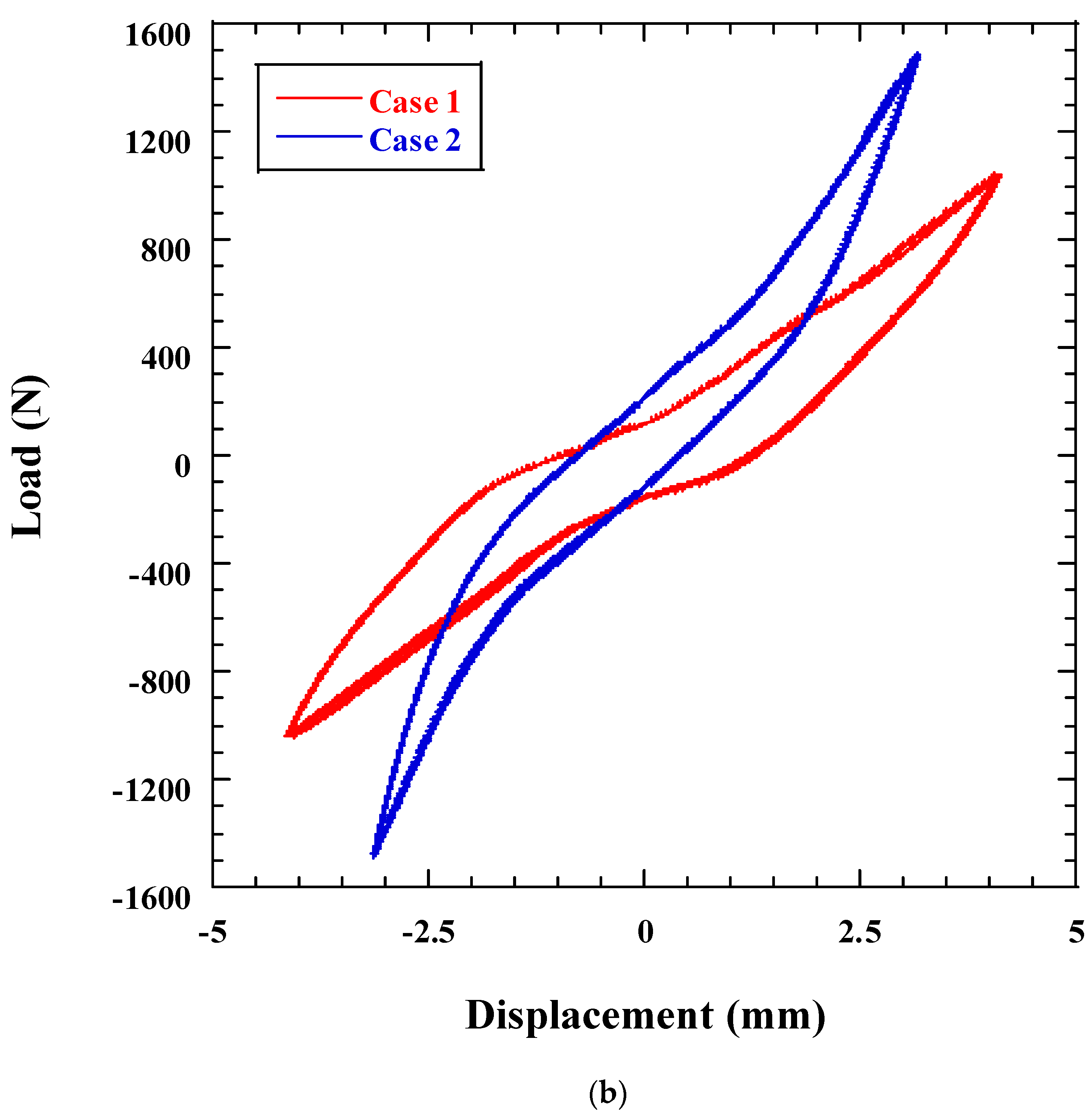
Figure 3a,b show the load displacement relations obtained from the static load test of the WSVI in the lateral and axial directions for Cases (1) and (2). These test results show that the equivalent stiffness of Case (2), with a blade thickness of 1.5 mm, is 1.7 times higher than that of Case (1), with a 0.8 mm blade. In the test, the boundary layers of the thin plates with viscous lamina tapes did not delaminate, and no plastic deformation was observed on the SMA blade within the tested range of translational loading. Because all subsequent curves completely coincided with the initial hysteresis curve, even though the structural analysis results from the blades made of titanium and aluminum showed a negative margin of safety. Furthermore, the results showed a much larger hysteresis area, which cannot be achieved by general metal materials, including superplastic SMA [
12]. This is because the slip and friction induced by strong molecular attraction forces between multi laminated plates with the viscous lamina tape helped enhance the damping capability of the WSVI, because of the larger shear deformation and strain on the multi- laminated SMA blades. In addition, the WSVI in the axial direction showed a much higher damping characteristic than that in the lateral direction because a 2.5 times larger area of the hysteresis curve was obtained. This can be explained by the fact that the shear deformation of the SMA blades arranged in the axial direction is larger than that in the lateral direction. A structural analysis of the SMA blade for the axial direction also showed a 2.2 times greater maximum strain than that of the blade for the lateral direction. The test results also showed that the hysteresis area obtained from Case (2) was almost the same or slightly less than that of Case (1). Moreover, a nonlinear characteristic induced by the phase transformation of the superplastic SMA blade was not observed within the tested displacement range. On the contrary, the stiffness of the WSVI in the axial direction increased as the displacement increased. This phenomenon seems to be mainly related to the WSVI design because the stiffness in the longitudinal direction of the SMA blade becomes dominant in determining the stiffness of the WSVI as the displacement increases. Therefore, these results from the static load test of the WSVI indicated that the design strategy of applying multi-layered viscous lamina to the SMA blades is a much more dominant factor in enhancing the damping of the isolator than the inherent damping performance of superelastic SMA. In addition, the multilayered viscous lamina contributes to reducing the stress acting on the thin SMA blade, owing to the viscoelasticity of the adhesive tapes [
17]. Furthermore, a previous study [
12] reported that a superelastic SMA developed for high damping SMA gear showed higher fatigue durability than titanium under cyclic loadings. Therefore, SMA blades may be useful for launch-vibration isolator applications.
The estimated values of the equivalent damping
for each case are summarized in
Table 3. The values of
in each direction were obtained by the following equivalent linearization method, in which the nonlinear stiffness and damping coefficients are translated into linear ones [
20].
where,
is estimated from the linear-curve fitting of the overall slope of the load-displacement curve.
is the area of the closed loop of the hysteresis curve and
is the amplitude of the displacement.
3. Design Validation Test
To verify the effectiveness of the proposed WSVI design under a launch vibration environment, i.e., performance of launch load reduction and structure safety of the WSVI, sine and random vibration tests were performed at the qualification level. Low Level Sine Sweep (LLSS) tests were performed before and after the vibration test to confirm the characteristic variations of the WSVI.
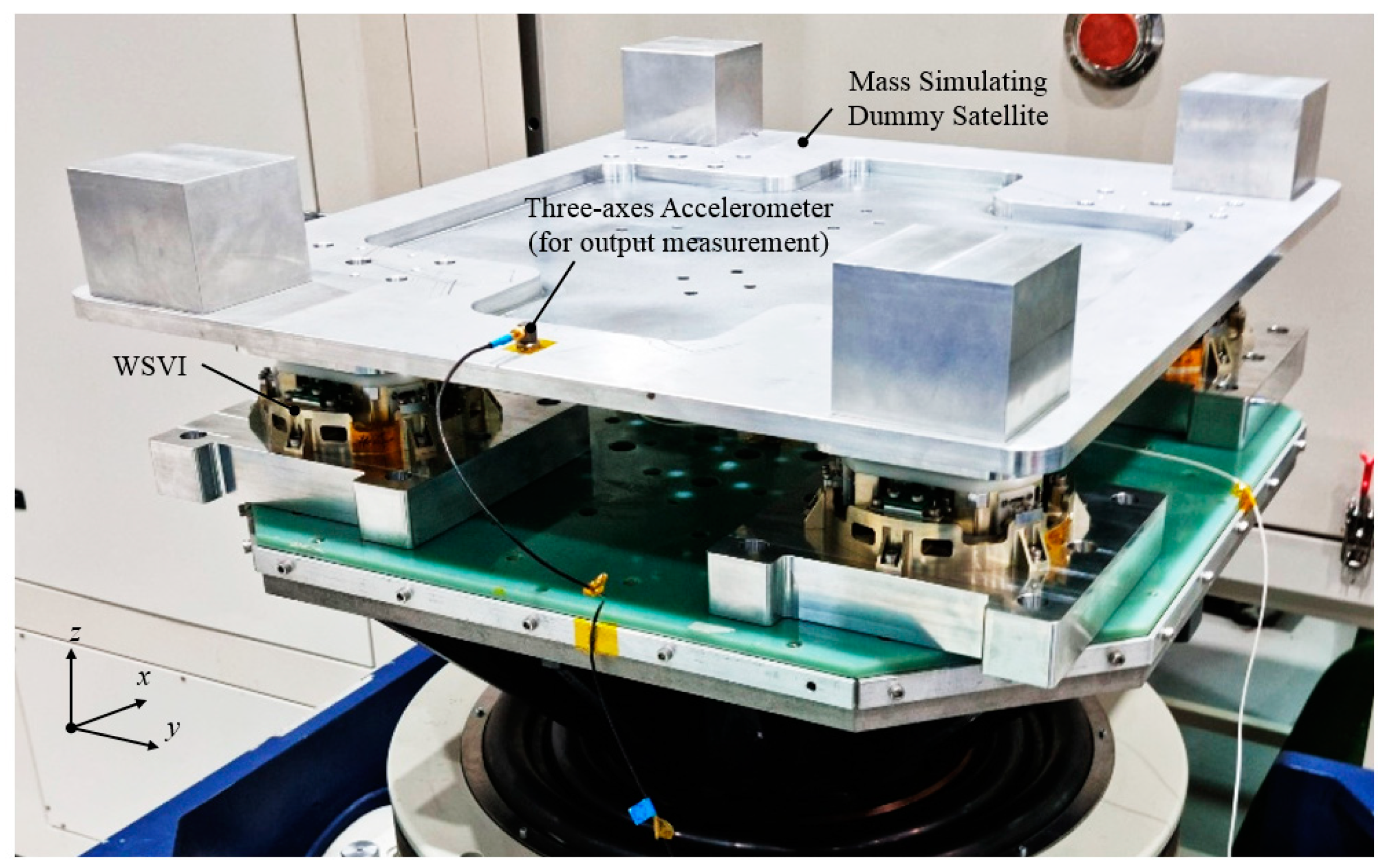
Figure 4 shows an example of the launch vibration test setup for the WSVI condition on the
z-axis. In the test setup, to achieve a 28 Hz cut-off frequency for a 40 kg class satellite, four WSVIs with the Case (1) design were integrated with a mass simulating dummy satellite. The dummy satellite was configured as a flat plate-type to implement the design concept of a small synthetic aperture radar (SAR) technology experimental project (S-STEP) satellite [
21]. The S-STEP satellite is an 80 kg class small SAR-satellite that provides a high resolution 1 m stripmap image. It was designed with a flat plate-type structure for mechanical design simplicity and high dimensional stability in orbit. In the test, the rigid mounted condition was also exposed to the vibration test for comparison with the WSVI. The vibration input from the vibration shaker was obtained from the reference accelerometer. The vibration responses for each axis of the WSVI were obtained from a three-axis accelerometer placed on the dummy satellite, as shown in
Figure 4. The qualification levels of the sine and random vibration test specifications applied to the design verification of the WSVI are listed in
Table 4 and
Table 5, and the axes of the test are shown in
Figure 4.
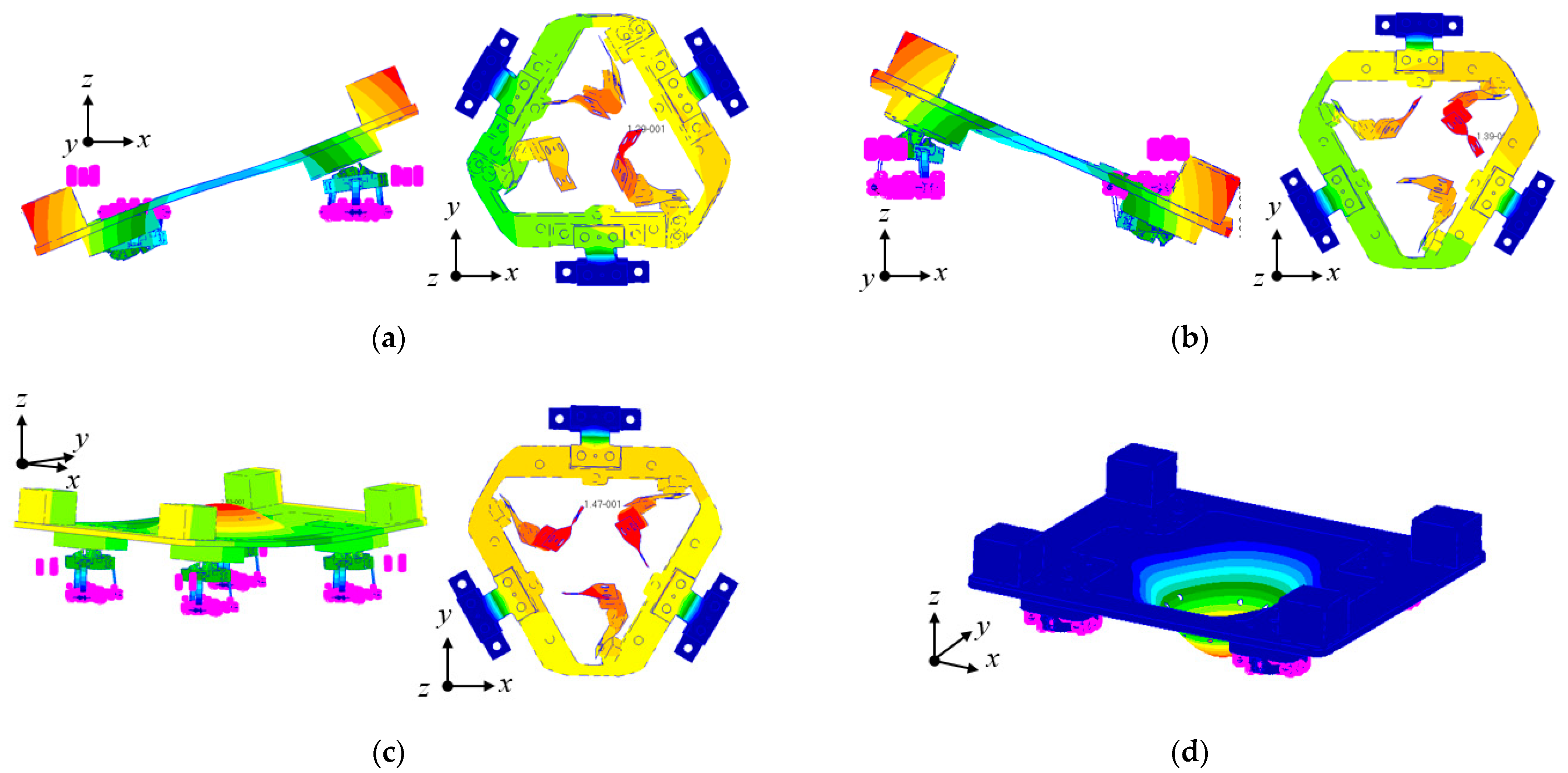
A modal analysis was performed to investigate the dynamic behavior of the dummy satellite combined with the WSVI.
Figure 5 shows the results of the modal analysis. The first and second modes at 28 and 30 Hz, respectively, mainly represent the bending mode of the blade modules for the lateral direction in the
x- and
y-axes. The third mode at 34 Hz indicates the bending mode of the blade modules of the WSVI in the axial direction along the
z-axis. The fourth mode at 40 Hz indicates the local bending mode of the center of the dummy satellite. These results were used to investigate the launch-vibration test results.
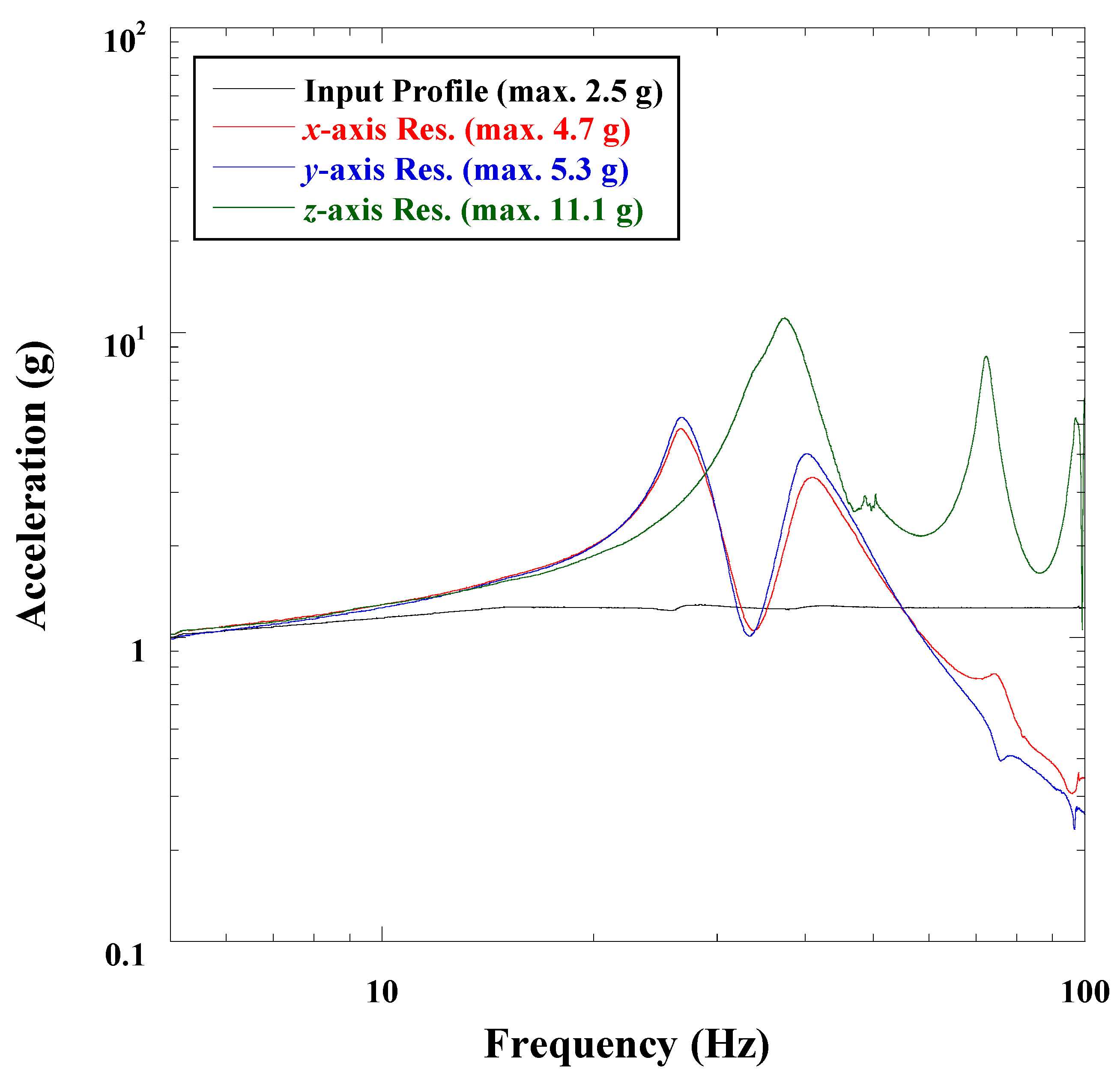
Figure 6 shows the sine vibration test results for the WSVI during the
x-,
y-, and
z-axis excitation. In the case of the
x-axis vibration response, the highest acceleration of the dummy satellite with the WSVI was 4.7 g at 28 Hz, which corresponds to the bending mode of the SMA blade modules for the lateral direction of the WSVI along the
x-axis. This value is almost similar to the estimated first eigenfrequency of 28 Hz from the modal analysis results shown in
Figure 5. In addition, the second response was followed by approximately 43 Hz, which was induced by the rotational mode of the SMA blade modules for the lateral direction of the WSVI along the
z-axis. The
y-axis response shows that the highest acceleration of 5.3 g was at 28 Hz. The overall tendency shows characteristics similar to the
x-axis result, owing to the symmetric configuration of the test setup. The
z-axis response shows the highest acceleration of 11.1 g at 35 Hz, which is similar to the estimated third eigenfrequency of 34 Hz. This response is higher than that of the
x- and
y-axes because of the coupling with the fourth mode of the structural elastic mode of 40 Hz for the test dummy structure. In addition, the second and third peak responses were followed at 72 and 98 Hz from the structural mode of the dummy satellite. From the sine-vibration test results, it can be seen that the highest acceleration response obtained from each of the
x-,
y-, and
z-axes did not exceed the design load of 23 g, derived from the mass acceleration curve (MAC) [
22]. This indicates that the WSVI is effective for attenuating sine vibration loads, as the design intends.
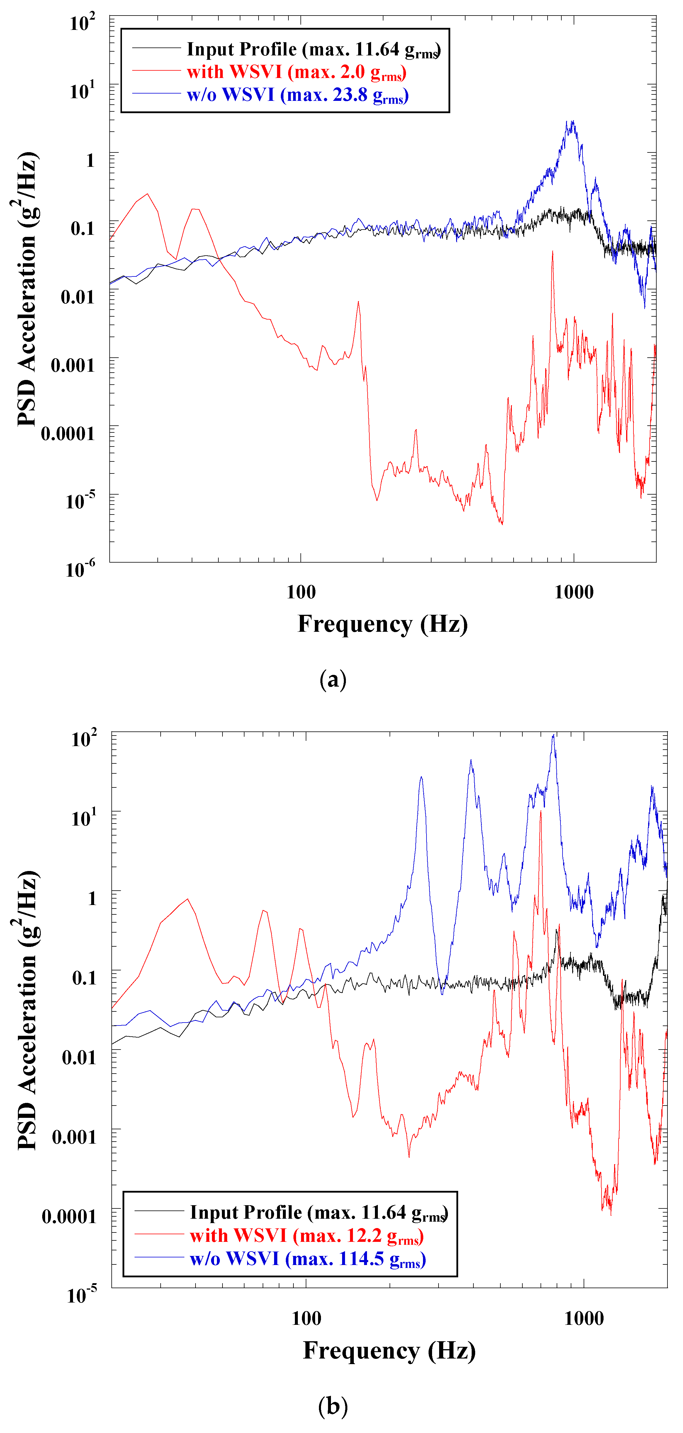
Figure 7a,b show the representative random-vibration test results for the WSVI during the
y- and
z-axis excitation. To compare the vibration-reduction capabilities of the WSVI, the test results obtained from the rigid-mounted condition are also plotted in the Figure. The
x-axis test result is not shown here, owing to the symmetrical configuration of the WSVI in the
x and
y planes, as mentioned in the sine-vibration test results. In the case of
Figure 7a, the first eigenfrequency of the dummy satellite without the WSVI was observed at 975 Hz and a maximum acceleration of 23.8 g
rms was observed, with respect to the random test input of 11.64 g
rms. However, the maximum acceleration was significantly decreased to 2.0 g
rms by applying the WSVI, and the random-vibration response was reduced by a factor of 11.9, comparing with the rigidly mounted condition. The maximum acceleration response along the
z-axis without the WSVI was 114.8 g
rms at 260 Hz. This response is higher than that of the
y-axis because the structural elastic modes of the dummy satellite are dominant along the
z-axis. However, the maximum acceleration of the dummy satellite with the WSVI was also significantly reduced to 12.2, as shown in
Figure 7b. This indicates that the output response is reduced by a factor of 9.4.
Table 6 summarizes the first eigenfrequencies of the dummy satellite with the WSVI in each axis, obtained through the LLSS tests performed before and after each vibration test. LLSS tests were performed to validate the structural safety of the SMA multilayered blade modules by investigating the dynamic responses of the dummy satellite with the WSVI. The results show that the maximum first eigenfrequency shift was within 3.9% throughout the test event, which was within the 5% criterion of the vibration test [
23]. This indicated that no mechanical failures of the WSVI were observed, e.g., the plastic deformation or delamination of the SMA multi-layered blades with viscous lamina. This is because the interlaminated surfaces with the double-sided adhesive are effective in resisting the shear force acting on the multilayered blade with energy-absorption effects. These launch-vibration test results indicate that the SMA multi-layered blade is effective for ensuring the structural safety of the WSVI itself and reducing the transmitted launch loads to the dummy satellite, as the design strategy intended.


