Article

Simulation of a GOx-GCH4 Rocket Combustor and the Effect of the GEKO Turbulence Model Coefficients

1
Moscow Aviation Institute, National Research University, 125993 Moscow, Russia
2
German Aerospace Center (DLR), Institute of Space Propulsion, 74239 Hardhausen, Germany
3
Institute of Turbomachinery and Flight Propulsion, Technical University of Munich, 80333 Garching, Germany
*
Author to whom correspondence should be addressed.
Aerospace 2021, 8(11), 341; https://doi.org/10.3390/aerospace8110341
Submission received: 9 September 2021 / Revised: 7 November 2021 / Accepted: 9 November 2021 / Published: 12 November 2021
(This article belongs to the Section Aeronautics)

Abstract

:
In this study, a single injector methane-oxygen rocket combustor is numerically studied. The simulations included in this study are based on the hardware and experimental data from the Technical University of Munich. The focus is on the recently developed generalized k–ω turbulence model (GEKO) and the effect of its adjustable coefficients on the pressure and on wall heat flux profiles, which are compared with the experimental data. It was found that the coefficients of ‘jet’, ‘near-wall’, and ‘mixing’ have a major impact, whereas the opposite can be deduced about the ‘separation’ parameter Csep, which highly influences the pressure and wall heat flux distributions due to the changes in the eddy-viscosity field. The simulation results are compared with the standard k–ε model, displaying a qualitatively and quantitatively similar behavior to the GEKO model at a Csep equal to unity. The default GEKO model shows a stable performance for three oxidizer-to-fuel ratios, enhancing the reliability of its use. The simulations are conducted using two chemical kinetic mechanisms: Zhukov and Kong and the more detailed RAMEC. The influence of the combustion model is of the same order as the influence of the turbulence model. In general, the numerical results present a good or satisfactory agreement with the experiment, and both GEKO at Csep = 1 or the standard k–ε model can be recommended for usage in the CFD simulations of rocket combustion chambers, as well as the Zhukov–Kong mechanism in conjunction with the flamelet approach.

1. Introduction

The recent and near-future developments in aerospace propulsion concern the use of high-energetic and simultaneously clean propellants. As one of such propellant, methane is proposed for wide use, while some aerospace engines and energetic systems already operate on the propellant combinations including methane. Alongside this, the numerical methodologies used to simulate combustion and its coupling with turbulence in either low- or high-pressure aerospace combustors are still incomplete, and a unique or straightforward methodology for application during the development and design processes still does not exist.
The application of the models for physical phenomena such as turbulence and combustion (and its interaction), as well as mixing, still poses many questions. Recently, much attention has been afforded to the choice of the approaches to model rocket propulsion-oriented cases.
Perakis et al. [1], using a multi-element combustor test case, compared the performance of two turbulence models–k-omega SST and k-epsilon in combination with the steady laminar flamelet combustion model. It was found that the k-epsilon model generally results in higher eddy-viscosity (EV) values than the SST model, and therefore resulting, through enhanced mixing, in higher absolute pressures and heat fluxes. In other works, Perakis et al. [2,3] studied the heat flux prediction in multi-element and single element hydrogen– and methane–oxygen combustors and demonstrated a satisfactory accuracy in the results, based on the Favre-averaged Navier–Stokes equations (FANS). They present a non-adiabatic flamelet model, which accounts for low-energy near-wall effects in terms of reaction kinetics, maintaining a low usage of computational resources and still accounting for finite rate kinetics.
Zhukov et al. [4] performed a simulation of a single injector methane–oxygen combustor using the adiabatic steady laminar flamelet and the k-epsilon turbulence models and by employing a chemical mechanism by Zhukov [5] for the flamelet generation. A good agreement of the 2D simulations with the experiment was observed for the chamber pressure and the wall heat flux.
Roth et al. [6] performed a comparative study of the combustion models, using the same single-injector coaxial combustor from TUM. The study, aiming to comparing a finite-rate model, a non-adiabatic flamelet model, and an equilibrium chemistry model in a FANS, found that the finite-rate approach resulted in the best performance. However, its unstable convergence and high CPU and RAM requirements compared to other models have led the authors to propose further enhancements of the non-adiabatic approach, which is found to be faster and more robust, and more suitable to everyday engineering simulations.
Several comparative studies have been made using both multi- and single-element combustors designed at the Technical University of Munich [7,8,9,10]. It was found that the FANS-based approaches continue to perform relatively well for such applications, both for the 2D and 3D settings, and the primary influence on the simulation results is introduced by the combustion model, the turbulence model, and the approach for the turbulence-chemistry interaction. Although, a significant impact of the turbulence diffusion coefficients has been found.
Similar 2-dimensional FANS studies have also been produced for other popular combustors, for example, Poschner and Pfitzner studied popular Mascotte O2/H2 combustor using 2D FANS simulations and showed the high impact of turbulence model coefficients on the flame shape [11].
Zhukov carried out the numerical study of the PennState combustor and the impact of the numerical model on results [12]. He found that the wall heat flux highly depends on the model of mixture transport properties.
De Giorgi et al. simulated the two Mascotte test cases (H2/O2 and CH4/O2) and compared the calculated and experimental flame shape based on a 2D case setting and obtained a good agreement with the experimental flame shape [13].
Some other papers present studies on the effects of the turbulence model for various combustion applications such as gas turbines, model flames, or energy systems [14,15,16,17,18] and illustrate the critical importance of the turbulence model, especially in Reynolds-averaged or Favre-averaged frameworks. Oftentimes, the impact of the turbulence model appears varied. It is important to note that it not only affects the pressure/velocity fields but that the energy and scalars (species) strongly depend on turbulence through the turbulent diffusion term.
Some recent papers describing simulations of the single- and multi-element methane–oxygen combustors from TUM also focus on the application of different combustion models, scale resolving methods for turbulence (such as LES-large eddy simulation, etc.), and data-assisted simulations.
Zips et al. [19] studied a multi-element combustor using LES and different combustion models, comparing the performance of a non-adiabatic, frozen flamelet method and a higher fidelity TPDF (transported probability density function method). The non-adiabatic model performed better in the calculation of wall heat fluxes than the frozen flamelet model. However, the TPDF was more accurate in WHF than the non-adiabatic flamelet method. Another interesting result is that all models were able to reflect the effect of wall heat losses for the flowfield, but the mixture compositions were dissimilar. For future studies, the authors still propose the development of more accurate non-adiabatic flamelet models, as it is more computationally affordable model compared to the TPDF model.
In a following study, Zips. et al. [20] used a frozen flamelet approach with an LES model for turbulence and several high-fidelity wall treatments-wall-modeled LES, wall-resolved LES, and the hybrid and RANS/LES IDDES to study the combustion process in a single-injector square cross-section TUM combustor. The authors found that all the applied approaches showed good agreement in representing the heat flux and the pressure data. For future research, the authors mention using high fidelity non-adiabatic extensions of the flamelet model and of accounting for radiative heat transfer.
N. Perakis et al. [21] examined the combustion process in a coaxial single-injector methane–oxygen combustor from TUM. The application of a non-adiabatic flamelet with an LES method for turbulent fluctuations allowed for good results for heat fluxes and pressures compared with the experiment. The importance of accounting for heat release by recombination reactions in the low-energy boundary regions has been highlighted, and further studies using direct numerical simulations through finite rate chemistry were recommended for a more detailed study of these processes.
Breda and Pfitzner [22] performed a thorough analysis of the non-adiabatic flamelet approach coupled with an LES-Improved Delayed Detached Eddy Simulation (IDDES) turbulence modeling method. First, the preliminary sensitivity studies of the non-adiabatic approach were performed using a laminar test case, after which the mesh resolution issues were studied in the context of the IDDES approach, and finally, a simulation on a single injector test case for TUM was performed. The main result is the reasonable applicability of the IDDES coupled with a non-adiabatic extension of the flamelet approach for the simulation of similar propulsion cases.
Indelicato et al. [23] performed a numerical study of a single-injector combustor from TUM using both 2D and 3D URANS approaches. A new non-adiabatic flamelet model was applied, which showed good agreement with the experimental data both for wall heat fluxes and pressures.
Chung et al. [24,25] proposed a data-assisted study of a single-injector methane–oxygen TUM combustor using a random forest classification algorithm. The objective was to test the usage of the random forest classifier method for dynamic combustion model assignment, based on the local scalar properties of the flowfield. The finite-rate chemistry combustion model was considered most accurate for the flamelet progress variable method and the inert mixing model, therefore the LES-based simulation with the FRC model served as the main learning dataset for classification. The results showed good performance and a high potential for application in future simulations. Moreover, more computationally efficient and accurate models were proposed for further studies.
Though the number of high-fidelity large eddy simulation studies is constantly growing based on the general computational power rising trends, Reynolds-averaged Navier-Stokes (and Favre-averaged in case of compressible flows) simulations are still used for a lot of aerospace propulsion problems due to the high complexity of the physics, and owing to their usefulness in engineering routine simulations. This is confirmed by new RANS turbulence models being developed constantly, one of these being the new GEKO (generalized equation k-omega) model, which has been recently implemented in ANSYS Fluent and ANSYS CFX. This model allows for the variation of the constants within the predefined limits without losing the model consistency, in contrast to currently adopted approaches, where the constants are defined on the model calibration stage using conventional test conditions, and their future change can affect the validity of the model. However, there have not yet been any thorough studies performed of this model as applied to reactive flows in combustors of any type. Therefore, this model was studied in this paper, to understand the impact of the coefficients in the reacting environment in a test case combustor.
As seen from previous studies, the combustion modeling approach is no less important than a turbulence model, and chemical mechanisms may lead to a considerable effect on the results. At the same time, PDF-based approaches, and, namely, the steady laminar flamelet model are widely used for simulations in propulsion applications and provide an advantage over finite-rate or eddy-dissipation concept model due to the requirement to solve fewer transport equations, meaning that it is more robust and less consuming. In this study, for the engineering approaches, i.e., the approaches that can be used for routine optimization studies, the flamelet model was used. In this paper, therefore, two reaction mechanisms are used to study the influence on the resulting flowfield: RAMEC [26] and Zhukov–Kong [5], which can be considered as a reduced version of RAMEC. Both mechanisms were validated across a wide range of conditions and are applicable for the current simulations, making a comparison of the reaction’s treatment and turbulence model constant effects easy to compare, which would be useful for the application of the approach to model.

2. Modelling Object and Methods

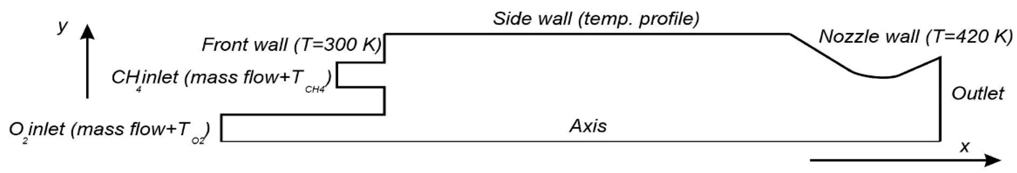
2.1. Object of Modelling

A single-element cylindrical combustor designed and experimentally studied at the Technical University of Munich (TUM) was used as a suitable test case [27,28]. The combustor operated on gaseous methane and oxygen, while the circular geometry and a single injector allow for the creation of axisymmetric 2D simulations, saving on computational resources and proving suitable for the objectives of the present study. Another advantage of the 2D-axisymmetric nature is that for the study of a turbulence model, such as GEKO, it eliminates uncertainties from 3D effects (near-wall secondary flow, etc.), and is therefore preferential for the primary turbulence model estimation (a 3D study of the GEKO model, nevertheless, would be desirable for future).
The pressure axial profiles are available in the experimental data, with the heat flux profile. The hot-runs were performed at different oxidizer-to-fuel ratios (ROF) both for the methane and hydrogen, and one operation point for methane is used for the simulations—ROF 2.2 because it has already been studied by other groups [4,29]. The present ROF = 2.2 employs the mass flow rates of methane and oxygen equal to 0.0153 kg/s and 0.0339 kg/s, respectively, and their temperatures are 268 K and 276 K, respectively. The measurement errors, mainly originating in the mass flow measurement uncertainty, have been reported by the authors [30] and analyzed by other researchers [4]. The estimated measurement errors amount to 4% for pressures and 10% for heat flux, being typical for test combustors of this type.

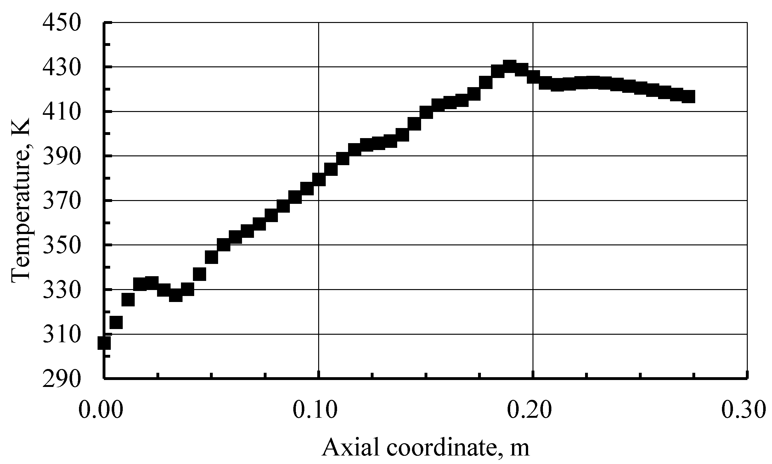
2.2. Boundary Conditions

The boundary conditions constitute the main difficulty in the CFD modeling of rocket combustion chambers. This issue affected the choice of the test case for the present study since the boundary conditions of this particular case are better described in comparison to other published experimental data. Due to the limited amount of data the pressure and wall heat-flux axial profiles and the calibration of the GEKO model will be performed with some uncertainty, and the additional contribution of boundary conditions uncertainty is negligible.
The scheme of the boundary conditions is shown in Figure 1. All of the walls are assumed to be smooth and non-slip. On the sidewall of the chamber, the temperature profile is applied. The real walls are, of course, not optimally smooth possess a certain temperature distribution along the surface that is not uniform. We assume that these differences insignificantly affect the numerical results. The experimental temperature profile is applied, which is shown in Figure 2, at the sidewall.

2.3. Numerical Setup

In this study, the Favre-averaged Navier-Stokes equations are solved using a pressure-based pseudo transient coupled ANSYS Fluent algebraic multigrid solver in a 2-dimensional axisymmetric problem formulation. The second-order discretization schemes are used for all species and energy scalars as well as for momentum, density, and pressure. The explicit under-relaxation factors of 0.1 are used for all equations. An automatic timescale method is used for the solution propagation, and a default value of 1 is applied to the timescale factor. These settings can be different for optimal convergence performance and a speed-up of the solution for other software, however, and are only presented here as a reference. The calculation is complete when the convergence of the residuals is at least 10−4 for all equations. A default non-adiabatic approach implemented in Fluent is used for the formation of the flamelet library file from CHEMKIN mechanism files [5,26]. The initial number of the grid of 25 and the maximum number of 200 are used to generate the look-up tables using automated grid refinement, whereas the values of 0.25 are used for the maximum changes in value and slope ratios. This default ‘non-adiabatic’ approach incorporates the dependency of mean temperature and density scalars on the mean enthalpy level in the look-up tables based on flamelet profiles, convoluted with the presumed probability density function to generate these tables. However, the mean species mass fractions do not depend on the enthalpy level and therefore the effect of heat/loss gain on the species mass fractions is not taken into account. Thus, the species concentrations are constant for different enthalpy levels and correspond with the concentration values equal to the adiabatic conditions. As the implementation of a fully non-adiabatic flamelet concept was not an objective in this paper, and because the study mainly focuses on the comparison of the turbulence model parameters, this approach is used here to simplify the setting.
A low-Re mesh criterion for the non-dimensional wall distance y+ ≤ 1 is satisfied along the combustor wall. The numerical mesh is completely analogous to the mesh used by Zhukov et al. for the same combustor [4]. Based on a preliminary mesh convergence study shown in Table 1 and Figure 3, a total grid size of 117,000 nodes (3rd grid) has been used.
The mixture viscosity and the thermal conductivity are calculated using the Wilke mixing law [31] and Mason and Saxena approach [32,33], respectively. The individual species properties are taken from McBride et al. [34]. The impact of radiative heat transfer and the wall roughness are disregarded in the present study for simplicity.
Here, as already noted, the steady laminar flamelet model is used for combustion whereas a probability density function approach based on the beta function is applied for the turbulence–combustion interaction, which is used in its default configuration in Fluent. Two chemical mechanisms are used to generate the look-up tables in the current study-the Zhukov and Kong reaction mechanism [5] and the well-known RAMEC mechanism. Both mechanisms have a well-established history of application and are selected here for a performance comparison and to estimate the impact of the kinetic mechanism compared to the impact of the turbulence modeling settings, which is the primary objective in this study.
The turbulent Prandtl and Schmidt numbers, equal to 0.9 and 0.7, respectively, are used for all simulations, regardless of their influence on the simulation results [35,36] as the current study did not require them to be varied, and it was chosen to keep constant settings throughout the simulations.
Finally, the turbulence effects are primarily modeled using the Generalized k-omega model, which has been recently introduced into ANSYS CFX and Fluent software. Original and detailed information on the model formulation is not yet available, however, according to the description provided in the documentation [37,38,39], it offers a researcher with a tool to manually set the model coefficients for the specific case without compromising the model consistency. Although no details are provided on the position of the coefficients in the equations, several main coefficients are given: Csep—“the separation parameter”, Cmix—“the mixing parameter”, Cjet—“the jet parameter” and Cnw-“the near-wall parameter”. As the turbulent reacting flow in any combustor and especially in the discussed combustor is very complex, all these coefficients can affect the flow and therefore impact the resulting pressure and heat flux profiles. Thus, all four of these parameters have been chosen for the variation. To compare the GEKO model performance with a conventional turbulence model, several additional simulations are created using the standard k-epsilon model [38] and the results are compared to the GEKO model. The governing differential equations for the GEKO model can be found via ANSYS Fluent as follows:
( ρ k ) t + ( ρ U j k ) x j = x j [ ( μ + μ t σ k ) k x j ] + P k C ρ ρ k ω
( ρ ω ) t + ( ρ U j ω ) x j = x j [ ( μ + μ t σ ω ) ω x j ] + C ω 1 F 1 ω k P k C ω 2 F 2 ρ ω 2 + C D F 3 ρ
here, the variable coefficients, which can be tuned for better model operation, are implemented through the F1, F2, F3 functions, but unfortunately, they are not yet described in the available literature. However, as is described in the documentation, the model performance has already been tested during preliminary validation on well-known canonical cases [37].

3. Discussion and Results

In this section, the results of the numerical simulations of the present single-injector combustor are presented. To study the effect of the GEKO model coefficients, the values of the four coefficients are varied so as to maintain the default settings for other parameters. The ranges of the parameter variation are based on the recommendations given in the release notes [37,38]. The default values of the parameters provided by Ansys FLUENT are Csep = 1.75, Cjet = 0.9, Cnw = 0.5, and Cmix is calculated either from Csep values being coupled in its performance or is equal to zero. As very little information is currently available regarding the position of these parameters in the model equations, the discussion of its influence is limited to the listed recommendations. Besides, two kinetic mechanisms are studied–the Zhukov–Kong [5] and RAMEC [28] mechanisms, to decipher the comparative effect of the chemistry model coupled with the variations of turbulence modeling approaches.

3.1. Effect of the “Near Wall” Parameter

The “near wall” Cnw coefficient, as proposed by the authors of the GEKO model can modify the near-wall model performance under non-equilibrium conditions, which should affect heat transfer in reattachment areas. As heat flux is of high interest for the considered case, three values of Cnw have been studied and the results are presented in Figure 4. It can be seen that the effect of this coefficient is nearly negligible (all simulation curves lie behind each other) under the current operating conditions both for the pressure and the heat flux estimations. In Figure 4, all simulation curves are positioned behind one other. Besides, a good agreement can be observed between the experimental profiles and the simulation results.
The authors of the GEKO model do not provide a comprehensive description, namely, the mathematical description of its coefficients [37,38,39]. That is why the coefficients of the GEKO model are treated as empirical parameters in our work. According to [37], the coefficient of Cnw is designed to adjust the heat transfer predictions in the reattachment and stagnation regions and to eliminate their impact on the normal (flat plate) boundary layer. In the combustion chamber, we have a flow similar to a backward-facing step flow with heat transfer, and there is a corresponding stagnation point on the sidewall, which is visible on the wall heat flux profile. However, due to the fact that the length of the combustion chamber is one hundred times (305 mm/3 mm) larger than the distance from the injector to the side wall [27], the flow at this stagnation region has a negligible effect on the heat transfer in the chamber as a whole.

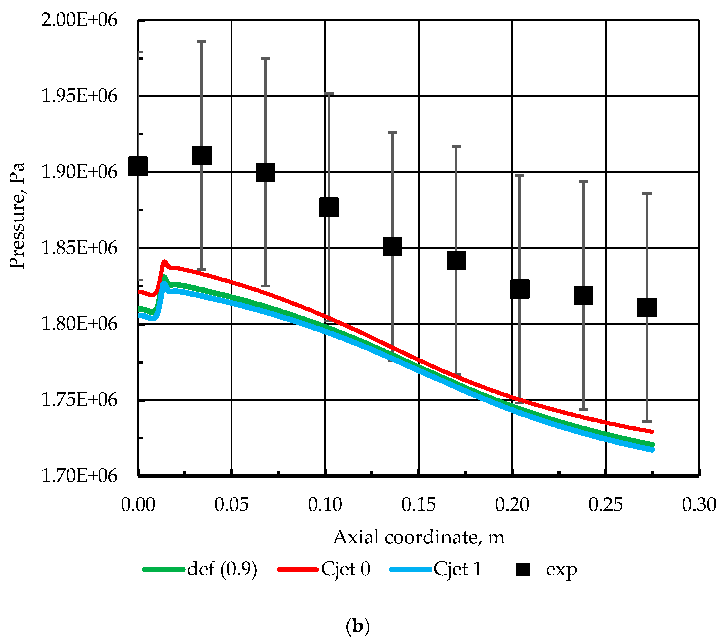
3.2. Effect of the “Jet” Parameter

The Cjet coefficient, based on the documentation guidelines, is not suggested to be a primary parameter for performance augmentation and might be important in regions with round jets. Due to the circumferential geometry and the presence of two concentric injectors in the discussed combustor, this coefficient is also chosen for variation. The results are presented in Figure 5. Here, a relatively small effect can be observed for the Cjet = 0 which is expressed in the 0.1 bar higher pressures in the near-injector region and in the slightly higher wall heat fluxes.

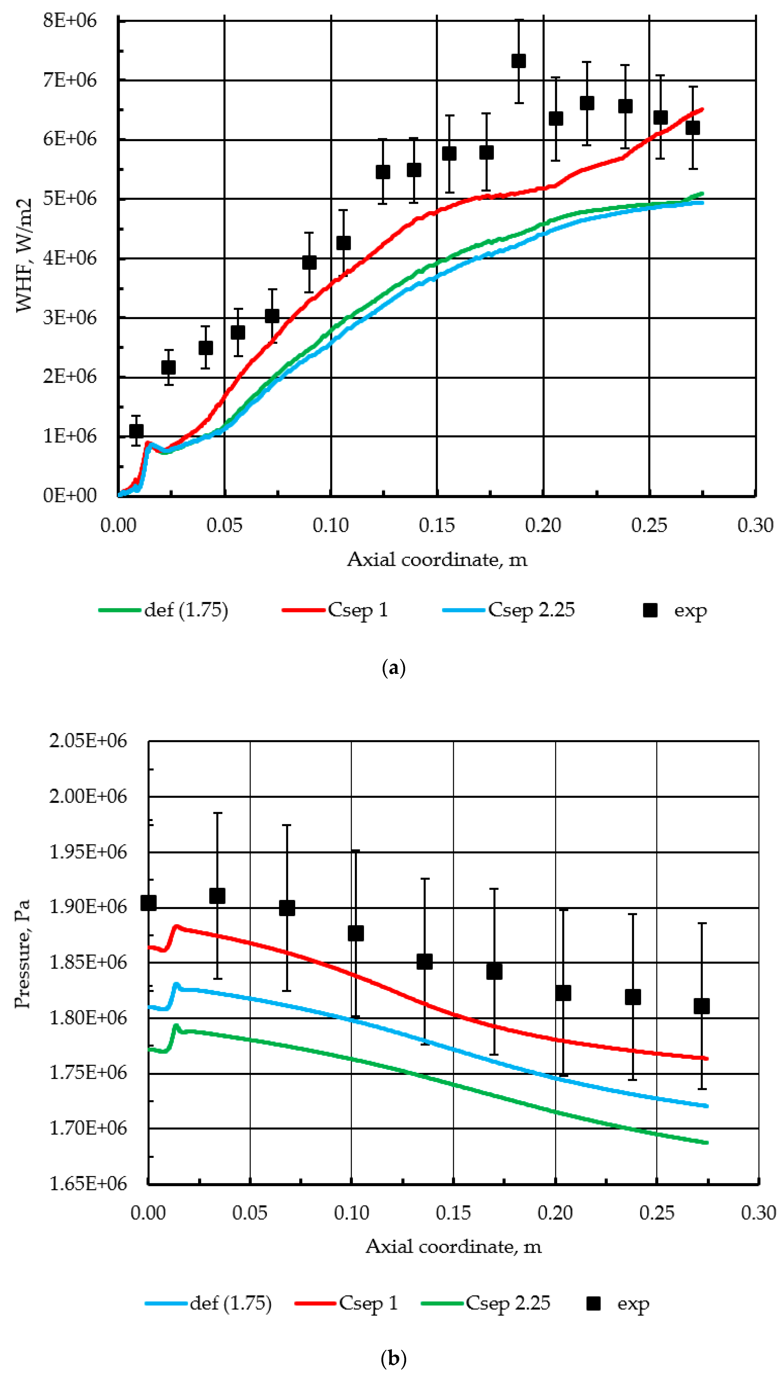
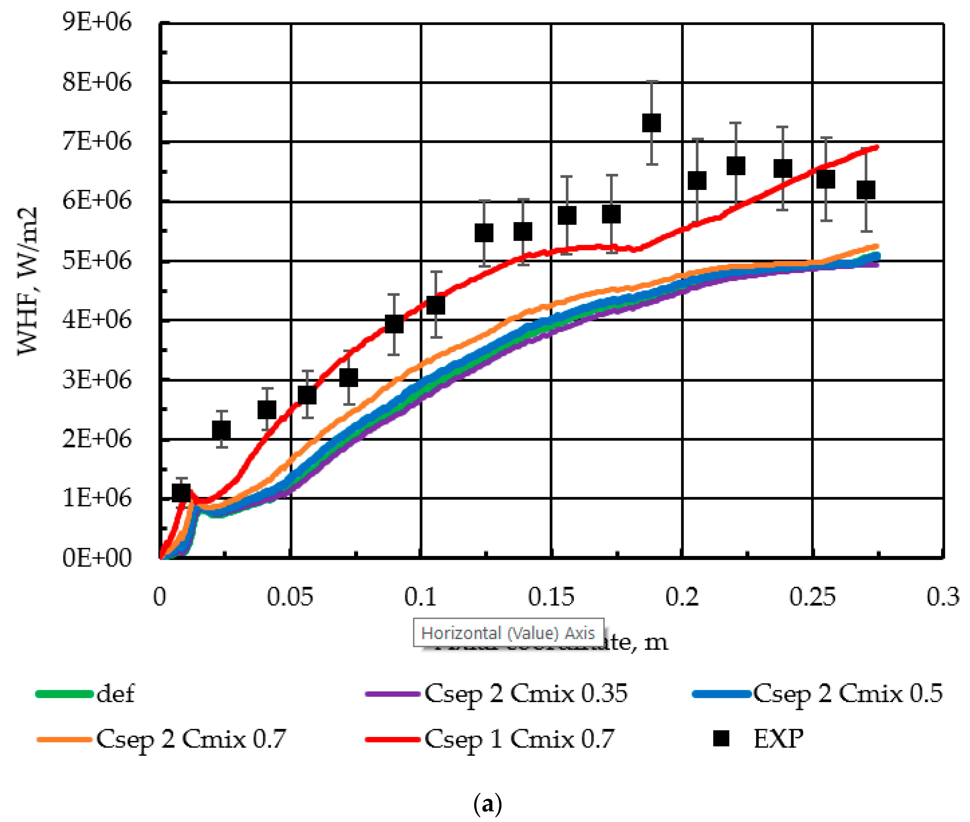
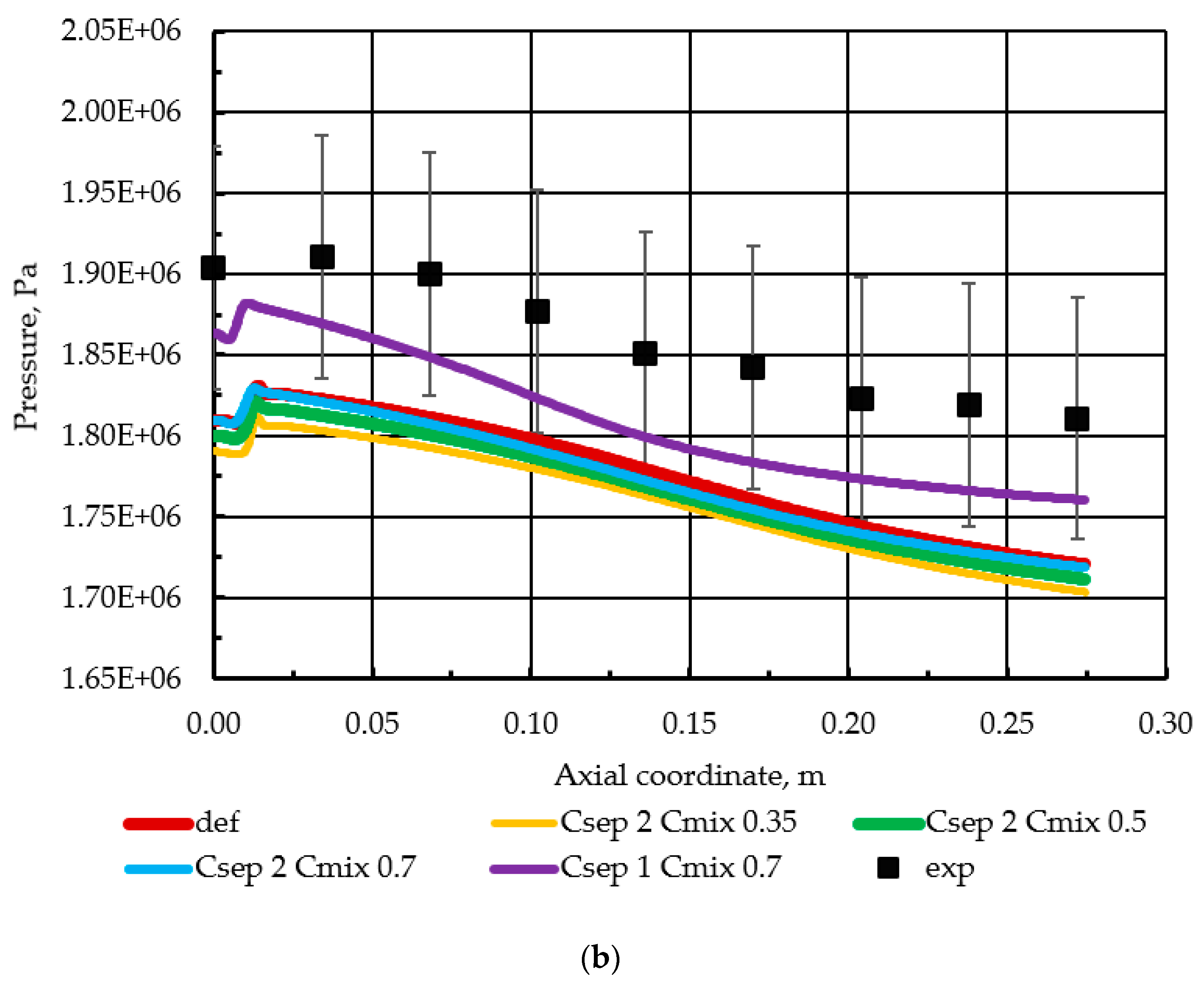
3.3. Effect of the “Separation” Parameter

To improve the model performance in situations of adverse pressure gradients and the separation effects by predicting the logarithmic layer slope, both with the viscous-turbulent layer transition, the calibration of Csep (“separation” coefficient) is required. This coefficient is expected to primarily affect the flowfield when using the GEKO model and is central for any adjustments required, especially in the flows that are dominated by boundary layers. Although, in the present case, the nature of fluid flow effects is very complex, and the model behavior in the near-wall area might be important for the wall heat flux and, as a result, the general pressure level. The influence of Csep is presented in Figure 6. The strong effect of Csep is easily observed for both the heat flux and pressures, while the values of Csep = 2.25 and Csep = 1.75 (default) provide similar results for heat fluxes. It can be seen that smaller values of Csep provide higher pressures and wall heat fluxes, which is possibly due to higher eddy-viscosity levels provided by smaller Csep values, which is discussed. The qualitative difference for the heat flux and pressure profiles slope can be observed with Csep = 1, compared to other values of higher mixing due to higher eddy-viscosity levels result in higher levels of heat produced in the first half of the combustor, which further leads to a lowering of the pressure and heat flux profiles in the 3rd quartile of the combustor. Finally, the underburned fuel components remix, which results in the rise of the heat flux and pressure in the 4th quartile. This behavior is somewhat different from the default model settings and the experimental heat fluxes profile slope but reproduces the experimental profile slope to a more accurate degree. This behavior, nevertheless, is discussed later.

3.4. Effect of the “Mixing” Parameter

Another parameter Cmix, a “mixing” parameter, should have an effect on free shear flows. In general, an increase of this coefficient should lead to higher eddy-viscosity values. Therefore, in the present study, an increase of the coefficient value has been considered for the mixing process of CH4 and O2, as the process is shear-dominated. It should again be noted, that the Cmix and Csep coefficients are naturally strongly coupled; thus, the variation of the Cmix parameter should be performed for certain Csep values. In this study, a Csep = 2 value is selected, and a single simulation using Csep = 1 is performed as a comparison. The resulting pressures and heat fluxes are presented in Figure 7. Similar behavior is observed both for Csep = 1 and Csep = 2 (as the one in Figure 6), while larger Cmix values are found to lead to higher pressures, as a result of greater eddy-viscosity values, leading to better combustion performance. Again, the Csep = 1 shows a qualitatively differing slope and much higher pressures.

3.5. Performance of the GEKO Model at Different ROF

It is essential that the behavior of a turbulence model changes with the variation of the operating conditions or the geometry of the object under study. As the experimental campaign, provided by the research group at TUM [30] on the single-injector methane-oxygen combustor, contains tests on other oxidizer-to-fuel ratios (ROF), the default GEKO model is tested using the same geometry for the ROF = 2.6 and ROF = 3. The mass flow rates and temperatures for these load points are provided in Table 2.
The resulting profiles for the pressure and the wall heat flux are displayed in Figure 8. It can be seen that the slope and the character of the profiles are similar for different ROF values, which indicates that the behavior of the GEKO model is similar for these cases. It is important to note, however, that the rise of the heat flux profile in the last quarter of the combustor is different for all of the studied ROFs (regardless of the higher peak in the injector region for ROF = 3), which is evidently due to additional amounts of the oxidizer being mixed with the partially burnt fuel at the end of the cylindrical section. Besides, the similarity of the GEKO behavior shows that the outcomes derived in Section 3.1, Section 3.2, Section 3.3 and Section 3.4 concerning the GEKO coefficients would be the same for differing ROFs. The following section, therefore, concentrates on the application of the RAMEC mechanism and the k-epsilon turbulence model for a general comparison with the results presented.

3.6. Effect of Detailed Kinetic Mechanism

To study the combined effect of the turbulence model and the chemical kinetics mechanism, RAMEC [26], which was initially created for ram accelerator conditions, is employed using the same steady laminar flamelet model. The two kinetic models are compared at the same turbulence modeling approaches, with the default GEKO model and the GEKO model with the “separation” parameter set as unity (Csep = 1), which has been displayed a positive and interesting performance, as discussed in Section 3.3 and Section 3.4. Furthermore, the conventional standard k-epsilon model is used for the comparison of the mechanisms. The results are presented in Figure 9.
The pressure distributions reveal a similar behavior of the Csep = 1 profiles compared to the default GEKO profile both for the Zhukov–Kong and RAMEC kinetics. It is also interesting that the k-epsilon model shows similar values for the Csep = 1 model, and therefore higher values than the GEKO default model. Previously, it was observed that the standard k-epsilon model provides higher pressures than k-omega based models (the shear stress transport model, for example) due to its higher combustion efficiency, originating from the enhanced turbulent mixing [1,2,8,36]. The heat flux values for k-epsilon and GEKO Csep = 1, show the same trend as for the pressure, having higher values for k-epsilon and Csep = 1. Such behavior is also shown to originate with the eddy-viscosity values. The eddy-viscosity field is shown in Figure 10 (only the Zhukov–Kong mechanism is taken here, as the turbulence modeling behavior for RAMEC and Zhukov–Kong is similar).
It can be seen that the k-epsilon model and Csep = 1 GEKO distributions show the highest values of turbulent viscosity, which are found in the recirculation area near the injectors. Quantitatively and qualitatively, the Csep = 1 and default GEKO models differ significantly, similar to the difference between the k-epsilon and the default GEKO turbulent viscosity distributions.
The wall heat flux and pressure profiles for the default GEKO and Csep = 1 in Figure 9 show similar behavior to the profiles in Figure 6 and Figure 7. Initially, it seems logical to assume that Csep = 1.75 (default) and Csep = 2.25 have a qualitatively better fit with the experiment, comparing the profile slopes. However, the comparison presented in Figure 10 shows that the default GEKO (Csep = 1.75) and Csep = 1 provide highly differing values of the eddy viscosities, e.g., in the near-injector area and the central part of the combustor. The contrast is also seen for the eddy-viscosity distribution, which is responsible for the differing profile slope for Csep = 1. This is also key to understanding the similarity between the profiles for Csep = 1 and the standard k-epsilon in Figure 9, providing insight into the reason behind the slight increase of the heat flux after 200 mm, compared to the k-epsilon model. The eddy viscosities are also higher for Csep = 1 in this area. The reason for heat flux dependence on the eddy viscosity is a higher intermixing of the reactants for greater turbulence intensities and a delayed reaction progress for lower eddy viscosity values. Therefore, the stabilization of heat flux for GEKO default (Csep = 1.75) occurs at lower values, while the wall heat flux growth begins earlier for Csep = 1 and k-epsilon, following its relative steepening at 180 mm and an additional, although small, wall heat flux increase after 210 mm explained by the eddy-viscosity distributions. Therefore, the differences between the profiles for the same kinetic mechanisms are mainly a result of the eddy-viscosity profiles, given by the specific turbulence model formulation.
Another feature of the pressure and wall heat flux profiles presented in Figure 9 is the quantitative difference between the Zhukov–Kong and RAMEC mechanisms. The RAMEC mechanism generally displays a lower pressure by around 0.3 bar and higher heat fluxes by around 0.9 MW/m2, which is reasonable, as lower pressure values result from a lower energy left inside the combustor, while the differences for turbulence models are around 0.1–0.4 bar and 0.1–1 MW/m2 respectively. However, the higher heat fluxes might be due to different species fields, resulting in different thermophysical and transport mixture properties. The distributions of the prevailing reaction products (CO2, H2O, and CO) and temperature are presented in Figure 11 (all presented contours have been retrieved using the standard k-epsilon model).
A significant difference in the species distributions can be observed for the two mechanisms. The mass fractions of complete oxidation products such as CO2 and H2O are, in general, higher for the Zhukov–Kong mechanism, which depicts a higher combustion efficiency and, therefore, higher pressure values. The greater difference in species and the less significant difference in temperature for these two mechanisms are explained by the fact that the objective function during the derivation of the skeletal Zhukov–Kong mechanism was the flame temperatures, but not species profiles. Furthermore, the high-temperature areas in the second half of the combustor are wider for the Zhukov mechanism, which can be explained by a higher energy loss for the case with the RAMEC mechanism. The comparison of the mechanisms in the CFD simulations has provided very interesting results. Both of the compared mechanisms use virtually the same thermodynamic data (enthalpies, entropies, and transport coefficients); however, they show similar although not identical results. The fact that the difference between the skeletal and detailed mechanisms become visible under the use of the flamelet approach, and the assumption of fast chemistry, was not evident prior to the study.
It should be noted that although the simulating results agree with experimental data within the limits of experimental error, the flamelet approach with a single-pressure table systematically predicts lower pressures in rocket combustors. A comprehensive explanation of the effect is provided by Zhukov in a recent article [40]. The gas possesses a higher temperature and the speed of sound in the nozzle throat but does not possess these characteristics in the simulations due to the additional heat released from the recombination reactions that are disregarded in the conventional flamelet method.

4. Conclusions and Outlook

A single-injector GCH4-GO2 combustor has been numerically studied with regard to the effects of turbulence and combustion modeling. The main focus of the paper was to study the effect of the GEKO model coefficients on the pressure and wall heat flux. This has been accomplished through a systematic study of the following four coefficients: ‘separation’, ‘near-wall’, ‘mixing’ and ‘jet’ parameters. Furthermore, the effect of the chemistry model is studied by using the following two mechanisms: Zhukov–Kong and detailed RAMEC.
In this study, we found that the ‘near-wall’ and ‘jet’ parameters have a minor or negligible impact on the pressures and heat fluxes under the considered operating conditions. The largest effect is evident for Csep, i.e., by the ‘separation’ parameter, and a lesser effect is evident for the ‘mixing’ parameter, which is, however, strongly connected in its influence with the applied Csep parameter value, due to documentation [37]. The decreasing Csep leads to higher eddy viscosity values and, therefore, a higher mixing and combustion efficiency, resulting in pressure and wall heat flux rises. The pressure and heat flux profiles are given by the lowest studied values of Csep = 1, and present a similar behavior to the values provided by the conventional standard k-epsilon model.
The influence of the kinetic model, at least for the studied mechanisms, is comparable to the influence of the ‘separation’ parameter adjustment of the GEKO model (or utilization of the standard k-epsilon model) rather than the default GEKO. The difference between the results for the Zhukov–Kong and RAMEC mechanisms, however, are addressed for different species fields and therefore different mixture properties. It has been shown that RAMEC, in general, results in higher wall heat fluxes, while the Zhukov–Kong mechanism provides better experimental pressure profiles. Due to higher estimated errors in the wall heat flux measurements, and also the absence of modeling of the radiative heat transfer, which can contribute to up to 10–15% of total wall heat flux depending on the wall properties and species concentrations [36,41,42,43,44], the Zhukov–Kong mechanism, which better agrees with the experimental pressures, can be recommended. Regarding the GEKO coefficients, Csep = 1 can be recommended as well as the standard k-epsilon model for further usage for the same applications, which may be beneficial for engineers in terms of convergence, having turbulence models built on a different basis (k-omega and k-epsilon) and demonstrating similar performances, and, in terms of GEKO, proving to be easily adaptable for the required application.
In general, the results obtained using the different models provide good or satisfactory agreements with the experimental data. Furthermore, the default GEKO model presents stable behavior for the three different ROF and reproduces the pressure and wall heat flux profiles well.
Future studies will address the use of the variable turbulent Prandtl and Schmidt numbers depending on flow parameters as well as the application of radiative heat transfer models. Furthermore, the eddy-dissipation concept model will be evaluated for modeling the turbulence-chemistry interaction using the same, as well as other additional, mechanisms [45].

Author Contributions

Conceptualization, E.S. and I.B.; methodology, E.S., I.B. and V.Z.; investigation, E.S.; resources, I.B. and E.S.; writing—original draft preparation, E.S., V.Z., I.B. and A.S.; writing—review and editing, E.S., V.Z., I.B., A.S. and O.J.H.; visualization, I.B. and E.S.; funding acquisition, I.B. All authors have read and agreed to the published version of the manuscript.

Funding

This research was funded by the Ministry of Science and Higher Education of the Russian Federation, grant number FSFF-2020-0014.

Conflicts of Interest

The authors declare no conflict of interest.

References

  1. Perakis, N.; Rahn, D.; Haidn, O.J.; Eiringhaus, D. Heat Transfer and Combustion Simulation of Seven-Element O2/CH4 Rocket Combustor. J. Propuls. Power 2019, 35, 1080–1097. [Google Scholar] [CrossRef]
  2. Perakis, N.; Strauss, J.; Haidn, O. Heat flux evaluation in a multi-element CH4/O2 rocket combustor using an inverse heat transfer method. Int. J. Heat Mass Transf. 2019, 142, 118425. [Google Scholar] [CrossRef]
  3. Perakis, N.; Haidn, O. Wall heat transfer prediction in CH4/O2 and H2/O2 rocket thrust chambers using a non-adiabatic flamelet model. Acta Astronaut. 2020, 174, 254–269. [Google Scholar] [CrossRef]
  4. Zhukov, V.; van Schyndel, J.; Saulo, G. Simulation of Single-Injector Methane Rocket Combustor Using Different Numerical Codes. In Proceedings of the 32nd International Symposium on Space Technology and Science, Fukui, Japan, 15–21 June 2019. [Google Scholar]
  5. Zhukov, V.; Kong, A. A Compact Reaction Mechanism of Methane Oxidation at High Pressures. Prog. React. Kinet. Mech. 2018, 43, 62–78. [Google Scholar] [CrossRef] [Green Version]
  6. Roth, C.; Perakis, N.; Haidn, O.J. Modeling combustion and heat transfer in a single-element GCH4/GOX rocket combustor. In Proceedings of the 7th International Conference on Fluid Flow, Heat and Mass Transfer (FFHMT’20), Virtual Conference, 15–17 November 2020; pp. 178-1–178-8. [Google Scholar] [CrossRef]
  7. Maestro, D.; Cuenot, B.; Chemnitz, A.; Sattelmayer, T.; Roth, C.; Haidn, O.J.; Daimon, Y.; Keller, R.; Gerlinger, P.M.; Frank, G.; et al. Numerical Investigation of Flow and Combustion in a Single-Element GCH4/GOX Rocket Combustor: Chemistry Modeling and Turbulence-Combustion Interaction. In Proceedings of the 52nd AIAA/SAE/ASEE Joint Propulsion Conference, Salt Lake City, UT, USA, 25–27 July 2016. [Google Scholar]
  8. Perakis, N.; Haidn, O.; Eiringhaus, D.; Rahn, D.; Zhang, S.; Daimon, Y.; Karl, S.; Horchler, T. Qualitative and Quantitative Comparison of RANS Simulation Results for a 7-Element GOX/GCH4 Rocket Combustor. In Proceedings of the 54th AIAA/SAE/ASEE Joint Propulsion Conference, Cincinnati, OH, USA, 9–11 July 2018; p. 54. [Google Scholar]
  9. Chemnitz, A.; Sattelmayer, T.; Roth, C.; Haidn, O.; Daimon, Y.; Keller, R.; Gerlinger, P.; Zips, J.; Pfitzner, M. Numerical Investigation of Reacting Flow in a Methane Rocket Combustor: Turbulence Modeling. J. Propuls. Power 2018, 34, 864–877. [Google Scholar] [CrossRef]
  10. Sternin, A.; Perakis, N.; Celano, M.; Tajmar, M.; Haidn, O. CFD-analysis of the effect of a cooling film on flow and heat transfer characteristics in a GCH4/GOX rocket combustion chamber. In Proceedings of the Space Propulsion Conference, Seville, Spain, 14–18 May 2018. [Google Scholar]
  11. Poschner, M.; Pfitzner, M. Real Gas CFD Simulation of Supercritical H2-LOX in the MASCOTTE Single Injector Combustor Using a Commercial CFD Code. In Proceedings of the 46th AIAA Aerospace Sciences Meeting and Exhibit, Reno, NV, USA, 7–10 January 2008. [Google Scholar]
  12. Zhukov, V. Computational Fluid Dynamics Simulations of a GO2/GH2 Single Element Combustor. J. Propuls. Power 2015, 31, 1707–1714. [Google Scholar] [CrossRef] [Green Version]
  13. De Giorgi, M.G.; Sciolti, A.; Ficarella, A. Application and Comparison of Different Combustion Models of High Pressure LOX/CH4 Jet Flames. Energies 2014, 7, 477–497. [Google Scholar] [CrossRef] [Green Version]
  14. Kirubakaran, V.; Bhatt, D. Effect of different turbulence model on prediction of lean blowout limit for micro gas turbine combustor. Adv. Mater. Process. Technol. 2020. [Google Scholar] [CrossRef]
  15. Yilmaz, H.; Cam, O.; Tangoz, S.; Yilmaz, L. Effect of different turbulence models on combustion and emission characteristics of hydrogen/air flames. Int. J. Hydrog. Energy 2017, 42, 25744–25755. [Google Scholar] [CrossRef]
  16. Jiang, L. A Critical Evaluation of Turbulence Modeling in a Model Combustor. In Proceedings of the ASME Turbo Expo 2012: Turbine Technical Conference and Exposition, Volume 1: Aircraft Engine; Ceramics; Coal, Biomass and Alternative Fuels; Controls, Diagnostics and Instrumentation, Copenhagen, Denmark, 11–15 June 2012; pp. 535–545. [Google Scholar] [CrossRef]
  17. He, D.; Yu, Y.; Kuang, Y.; Wang, C. Model Comparisons of Flow and Chemical Kinetic Mechanisms for Methane–Air Combustion for Engineering Applications. Appl. Sci. 2021, 11, 4107. [Google Scholar] [CrossRef]
  18. Jiang, L.Y. RANS Modeling of Turbulence in Combustors. In Turbulence Modelling Approaches—Current State, Development Prospects, Applications; InTech: London, UK, 2017; Chapter 7. [Google Scholar]
  19. Zips, J.; Traxinger, C.; Breda, P.; Pfitzner, M. Assessment of presumed/transported probability density function methods for rocket combustion simulations. J. Propuls. Power 2019, 35, 1–19. [Google Scholar] [CrossRef]
  20. Zips, J.; Traxinger, C.; Pfitzner, M. Time-resolved flow field and thermal loads in a single-element GOx/GCH4 rocket combustor. Int. J. Heat Mass Transf. 2019, 143, 118474. [Google Scholar] [CrossRef]
  21. Perakis, N.; Haidn, O.J.; Ihme, M. Investigation of CO recombination in the boundary layer of CH4/O2 rocket engines. Proc. Combust. Inst. 2021, 38, 6403–6411. [Google Scholar] [CrossRef]
  22. Breda, P.; Pfitzner, M. Delayed detached eddy simulations with tabulated chemistry for thermal loads predictions. J. Propuls. Power 2021, 37, 29–46. [Google Scholar] [CrossRef]
  23. Indelicato, G.; Lapenna, P.E.; Remiddi, A.; Creta, F. An efficient modeling framework for wall heat flux prediction in rocket combustion chambers using non adiabatic flamelets and wall-functions. Int. J. Heat Mass Transf. 2021, 169, 120913. [Google Scholar] [CrossRef]
  24. Chung, W.T.; Mishra, A.A.; Perakis, N.; Ihme, M. Data-assisted combustion simulations with dynamic submodel assignment using random forests. Combust. Flame 2021, 227, 172–185. [Google Scholar] [CrossRef]
  25. Chung, W.T.; Mishra, A.A.; Perakis, N.; Ihme, M. Random forests for Accelerating Turbulent Combustion Simulations. In Proceedings of the Third Workshop on Machine Learning and the Physical Sciences (NeurIPS 2020), Vancouver, BC, Canada, 11 December 2020. [Google Scholar]
  26. Petersen, E.L.; Davidson, D.F.; Hanson, R.K. Combust. Flame 1999, 117, 272–290. [Google Scholar] [CrossRef]
  27. Roth, C.; Silvestri, S.; Perakis, N.; Haidn, O. Experimental and Numerical Investigation of Flow and Combustion in a Single Element Rocket Combustor using GH2/GOX and GCH4/GOX as Propellants. In Proceedings of the 31st International Symposium on Space Technology and Science, Matsuyama, Japan, 3–9 June 2017. [Google Scholar]
  28. Negishi, H.; Nakajima, T.; Keller, R.; Gerlinger, P. Heat Flux Estimation on a Chamber Wall of GH2/GOx and GCH4/GOx Single Element Rocket Combustors. In Proceedings of the 31st International Symposium on Space Technology and Science, Matsuyama, Japan, 3–9 June 2017. [Google Scholar]
  29. Daimon, Y.; Terashima, H.; Tani, H. Numerical Investigation on Effects of Recess Variation upon a GCH4/GOX Shear Coaxial Combustion Chamber. In Proceedings of the 31st International Symposium on Space Technology and Science, Matsuyama, Japan, 3–9 June 2017. [Google Scholar]
  30. Celano, M.; Silvestri, S.; Schlieben, G.; Kirchberger, C.; Knab, O.; Haidn, O. Transregio SFB-TR40—Test Case 1. Single Element Combustion Chamber GCH4/GOX. In Proceedings of the Space Propulsion, Cologne, Germany, 19–22 May 2014. [Google Scholar]
  31. Wilke, C. A Viscosity Equation for Gas Mixtures. J. Chem. Phys. 1950, 18, 517–519. [Google Scholar] [CrossRef]
  32. Mason, E.; Saxena, S. Approximate Formula for the Thermal Conductivity of Gas Mixtures. Phys. Fluids 1958, 1, 361–369. [Google Scholar] [CrossRef]
  33. Warnatz, J.; Maas, U.; Dibble, R. Combustion Physical and Chemical Fundamentals, Modeling and Simulations, Experiments, Pollutant Formation; Springer: Berlin/Heidelberg, Germany, 2001; pp. 1–350. [Google Scholar]
  34. Mcbride, B.; Gordon, S.; Reno, M. Coefficients for Calculating Thermodynamic and Transport Properties of Individual Species; NASA Technical Memorandum 4513; NASA: Wachington, DC, USA, 1993. [Google Scholar]
  35. Zhukov, V.; Borovik, I.; Strokach, E. Numerical Study of the Influence of Turbulent Diffusion Coefficients and Turbulent Prandtl Number on the Reactive Flow Simulation in a Combustor. Russ. Aeronaut. 2020, 63, 713–720. [Google Scholar] [CrossRef]
  36. Strokach, E.; Borovik, I.; Haidn, O. Simulation of the GOx/GCH4 Multi-Element Combustor Including the Effects of Radiation and Algebraic Variable Turbulent Prandtl Approaches. Energies 2020, 13, 5009. [Google Scholar] [CrossRef]
  37. Menter, F.; Lechner, R.; Matyushenko, A. Best Practice: Generalized K-Ω Two-Equation Turbulence Model in ANSYS CFD (GEKO); Technical Report ANSYS; ANSYS Inc.: Canonsburg, PA, USA, 2019. [Google Scholar]
  38. ANYS. ANYS Fluent Theory Guide; ANSYS Inc.: Canonsburg, PA, USA, 2019; Volume 15317, p. R2. [Google Scholar]
  39. Menter, F.R.; Matyushenko, A.; Lechner, R. Development of a Generalized K-ω Two-Equation Turbulence Model. In New Results in Numerical and Experimental Fluid Mechanics XII: DGLR 2018; Notes on Numerical Fluid Mechanics and Multidisciplinary Design; Dillmann, A., Heller, G., Krämer, E., Wagner, C., Tropea, C., Jakirlić, S., Eds.; Springer: Cham, Switzerland, 2020; Volume 142. [Google Scholar] [CrossRef]
  40. Zhukov, V. Extended Eddy-Dissipation Model for Modeling Hydrogen Rocket Combustors. Combust. Sci. Technol. 2020, 192, 531–546. [Google Scholar] [CrossRef] [Green Version]
  41. Leccese, G.; Bianchi, D.; Nasuti, F. Numerical Investigation on Radiative Heat Loads in Liquid Rocket Thrust Chambers. J. Propuls. Power 2019, 35, 930–943. [Google Scholar] [CrossRef]
  42. Thellmann, A. Impact of Gas Radiation on Viscous Flows, in Particular on Wall Heat Loads, in Hydrogen-Oxygen vs. Methane-Oxygen Systems, Based on the SSME Main Combustion Chamber. Ph.D. Thesis, Universitaet der Bundeswehr, Muenchen, Germany, 2010. [Google Scholar]
  43. Mazzei, L.; Puggelli, S.; Bertini, D.; Pampaloni, D.; Andreini, A. Modelling soot production and thermal radiation for turbulent diffusion flames. Energy Procedia 2017, 126, 826–833. [Google Scholar] [CrossRef]
  44. Poitou, D.; El Hafi, M.; Cuenot, B. Analysis of Radiation Modeling for Turbulent Combustion: Development of a Methodology to Couple Turbulent Combustion and Radiative Heat Transfer in LES. J. Heat Transf. 2011, 133, 062701. [Google Scholar] [CrossRef] [Green Version]
  45. Sternin, A.; Hao, M.; Liu, J.; Haidn, O.; Tajmar, M. Turbulence and Combustion and Film Prediction in Rocket Application via Parameter Adjustment, Model Variation and Deep Learning Method; Sonderforschungsbereich/Transregio 40–Summer Program Report: 2019; Technical University of Munich: Munich, Germany, 2019. [Google Scholar] [CrossRef]
Figure 1. Schematic of the numerical domain (not drawn to scale).
Aerospace 08 00341 g001
Figure 2. Wall temperature profile.
Aerospace 08 00341 g002
Figure 3. Mesh independence study for wall heat flux.
Aerospace 08 00341 g003
Figure 4. (a) Effect of Cnw on wall heat flux; (b) Effect of Cnw on pressure.
Aerospace 08 00341 g004
Figure 5. (a) Effect of Cjet parameter on wall heat flux; (b) Effect of Cjet parameter on pressure.
Aerospace 08 00341 g005aAerospace 08 00341 g005b
Figure 6. (a) Effect of Csep on wall heat flux; (b) Effect of Csep on pressure.
Aerospace 08 00341 g006
Figure 7. (a) Effect of Csep on wall heat flux; (b) Effect of Csep on pressure.
Aerospace 08 00341 g007aAerospace 08 00341 g007b
Figure 8. (a) Wall heat flux: experiment and simulations at different ROF (def = 2.2); (b) Pressure: experiment and simulations at different ROF (def = 2.2).
Aerospace 08 00341 g008
Figure 9. (a) Wall heat flux: experiment and simulations for Zhukov–Kong kinetic mechanism; (b) Wall heat flux: experiment and simulations for RAMEC kinetic mechanism; (c) Pressure: experiment and simulations for Zhukov–Kong kinetic mechanism; (d) Pressure: experiment and simulations for RAMEC kinetic mechanism.
Aerospace 08 00341 g009aAerospace 08 00341 g009b
Figure 10. (a) Eddy viscosity field given by the default GEKO model; (b) Eddy viscosity field given by the standard k-epsilon model; (c) Eddy viscosity field given by the GEKO model with Csep = 1.
Aerospace 08 00341 g010
Figure 11. (a) H2O distributions given by the RAMEC mechanism, ½ axial scaling; (b) H2O distributions given by the Zhukov–Kong mechanism, ½ axial scaling; (c) CO distributions given by the RAMEC mechanism, ½ axial scaling; (d) CO distributions given by the Zhukov–Kong mechanism, ½ axial scaling; (e) CO2 distributions given by the RAMEC mechanism, ½ axial scaling; (f) CO2 distributions given by the Zhukov–Kong mechanism, ½ axial scaling; (g) Temperature distributions given by the RAMEC mechanism, ½ axial scaling; (h) Temperature distributions given by the Zhukov–Kong mechanism, ½ axial scaling.
Aerospace 08 00341 g011aAerospace 08 00341 g011b
Table 1. Grid independence study.
CriterionCoarse (1st)2nd3rdFine (4th)
Num. of cells, mio.0.0510.0740.1170.235
Max. pressure, bar16.417.918.318.35
Relative error, max pressure %---/---8.3792.190.28
Table 2. Mass flows and temperatures of the components at different ROF.
GCH4 Mass Flow, g/sGO2 Mass Flow, kg/sGCH4 Temperature, KGO2 Temperature, K
ROF 2.215.333.9268274
ROF 2.613.335.6269275
ROF 3.012.136.27270273
Publisher’s Note: MDPI stays neutral with regard to jurisdictional claims in published maps and institutional affiliations.

