1. Introduction
The growing interest in the development of highly capable nanosatellites for a wide range of scientific missions [
1,
2,
3,
4,
5] demands a substantial increase of the traditionally low success rate of this kind of miniaturized platforms, which were originally conceived for educational or technological demonstration purposes. Among the causes for their low success rate, the limited ground verification process, especially at sub-system and system levels, is a relevant one, often originating due to schedule and budget constraints.
Clearly, more extensive ground verification approaches for nanosatellites are required, to lead to a careful performance assessment of the spacecraft bus prior to launch. As a result, increasingly more studies are found in the literature addressing verification approaches of mission critical subsystems, such as the power [
6], propulsion [
7], attitude determination and control (ADCS) [
8,
9], and guidance, navigation, and control [
10,
11] ones, considered alone or in combination [
12,
13,
14].
The ADCS is one of the most challenging subsystems to test in relevant conditions. For hardware-in-the-loop testing, disturbance-free rotational dynamics shall be enabled. Furthermore, on orbit environment shall be recreated for exciting sensors and/or actuators, which, depending on the mission, may involve simulating magnetic field, sunlight, starry sky, infrared Earth.
A class of simulators that has been extensively used for spacecraft rotational dynamics is the one based on air bearings, as they offer nearly torque-free motion and a relatively low complexity level [
15]; they can also be employed for translational dynamic simulation, thus providing motion capabilities with up to six degrees of freedom (DoF) [
16,
17].
Dynamic hardware in the loop facilities are certainly not new. Perhaps the simplest type relies on the concept of wire suspension [
18,
19], while the most commonly employed solution relies on air bearings: indeed, air bearing simulators have been used for ADCS verification starting from the 1960s [
15]. They allow low friction motion, with unconstrained rotation over one (the local vertical) or two axes, and constrained motion in tilt angles, depending on the layout. This last can be categorized in three broad configurations, namely table-top [
20,
21], dumb-bell [
22], and umbrella [
23]. For a historical review of air bearing simulators, the reader is referred to [
15]. The main drawback of the air bearing based facilities is that they are quite heavy, especially due to balancing weights required to minimize the disturbance torque due to gravity.
More recently, the widespread CubeSat community has led many Universities towards the development of scaled down ADCS dynamic simulators [
24,
25,
26,
27,
28]. Being typically budget-driven, the reported implementations, despite being effective, often overlook final performance verification, which is either absent or covering some parts of the facility only [
29,
30].
Within this context, the Microsatellite and Space Microsystems Lab at University of Bologna has recently developed a 3DoF testbed, aimed at nanosatellites ADCS hardware and algorithms verification. Due to the large variety of nanosatellite missions already launched, or on their way, aiming at, e.g., Earth observation, in-orbit demonstration (IOD), remote sensing, astronomical observation, whether on or beyond Earth orbit, a single facility could hardly fit the needs of the entire range of ADCS hardware combinations. For designing and implementing our testbed, we considered as the target application scenario the one of nanosatellite missions in Low Earth Orbit (LEO) for remote sensing, IOD, or Earth observation, whose pointing requirements often fall in the range from tens of arcminutes to one degree [
31,
32,
33,
34]. Furthermore, since the most popular nanosatellite type is the 3U CubeSat [
35], we took this size as a reference, even though the facility can host nanosatellites of size up to 6U, and not necessarily compliant to the CubeSat standard.
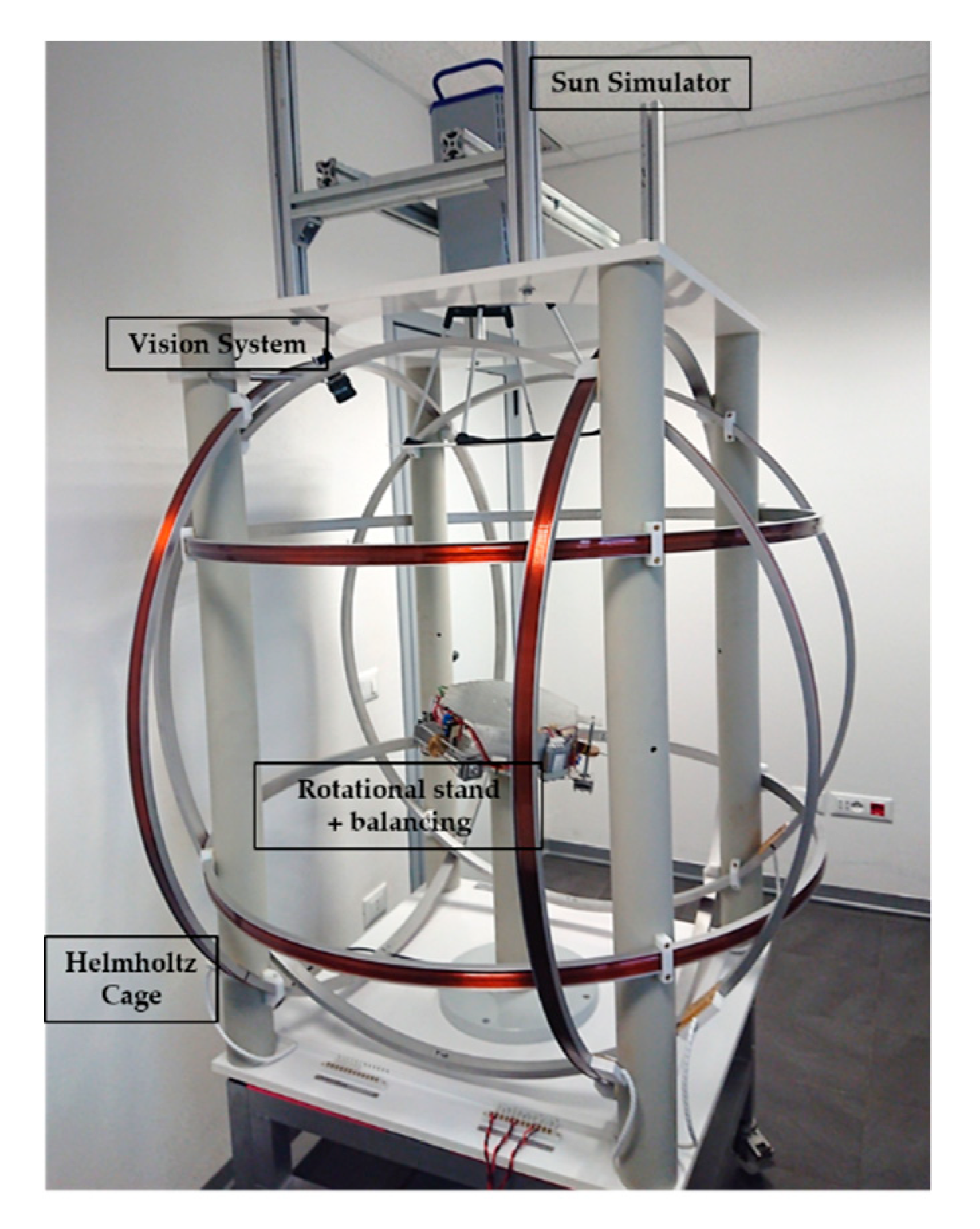
The core of the testbed described herein is a table-top air bearing platform, with custom design, whose function is to hold the nanosatellite mock-up under test; it includes an automatic balancing system with shifting masses actuated by linear motors, similar to the implementations in [
36,
37]. Other subsystems include a Helmholtz cage for geomagnetic field simulation, a Sun simulator, and a metrology vision system for ground-truth attitude measurement (see
Figure 1). Their development and verification required substantial efforts, aimed at achieving good performances, while meeting a rather low cost-cap (20 kEuro). This manuscript summarizes the main design choices, implementation details and verification steps carried out, and may, hopefully, represent a useful guide for analogous low-cost University projects.
As a point of technical novelty with respect to existing literature on air-bearing based testbeds with environmental simulation, this work presents the thorough verification of all subsystems integrated in the facility. Especially for in-house developments, this step is regarded as fundamental, yet often overlooked. Indeed, previous studies either described the facility without any performance verification or focused on the performance of one or two specific subsystems at most (see
Table 1). Chesi et al. provide results on the balancing system and the rated accuracy of the vision system of a testbed developed at the Naval Postgraduate School [
27]. Wu et al. provide accuracy data for the vision system of an air bearing testbed for spinning satellites developed at the Surrey Space Center [
30]. Da Silva et al. present the accuracy of the Helmholtz cage and the automatic balancing for a testbed developed at the LAICA laboratory, University of Brasilia [
28,
38]. Kato et al. describe the FACE facility at DLR Germany, rating accuracy for the Helmholtz cage only [
39]. Tavakoli et al. present a distributed ADCS testing facility with verified sunlight and magnetic field simulations [
8]. To the best of the authors’ knowledge, none of the existing works approaches the testbed integration with systematic performance verification for all its subsystems, a gap which is filled by this manuscript (
Table 1).
In particular, among the performance indexes verified as part of the development, a remarkable one is the disturbance torque acting on the articulated air-bearing, which has been reduced down to the 10
−5 Nm order combining structural design and automatic balancing, which are usually adopted separately [
36,
37,
38,
39,
40,
41].
This paper is organized as follows.
Section 2 describes the Helmholtz cage and articulated stand;
Section 3 details the customized testbed rotational platform, with focus placed on the automatic balancing system and on the structural design aimed at minimizing the deformation.
Section 4 describes the Sun simulator, with emphasis on the collimating lens calibration for minimizing beam divergence.
Section 5 describes the ground truth monocular vision system, including the algorithms developed and the test campaign for accuracy assessment.
Section 6 summarizes the main results of the commissioning phase of the whole facility, along with a perspective on future developments.
2. The Helmholtz Cage and Articulated Stand
Magnetic-based attitude control through torque-rods or coils is almost ubiquitously found on board nanosatellites in Earth orbit [
42], so that geomagnetic field simulation is often required for ADCS verification. The envelope of our facility is represented by a triaxial magnetic field simulator, housing a rotational stand with air bearing in its center. The Helmholtz cage (Ferronato
® BH-1300-3-C from Serviciencia, Toledo, Spain), features three orthogonal pairs of coils (D ≈ 1300 mm) that can generate an arbitrary magnetic field in the range ±10 Gauss. Magnetic field in-homogeneity is below 1% (5%) in a spherical volume of 404 (586) mm in diameter, concentric with the coil pairs. The nominal field-to current ratio is 50.5 μT/A, ±1%.
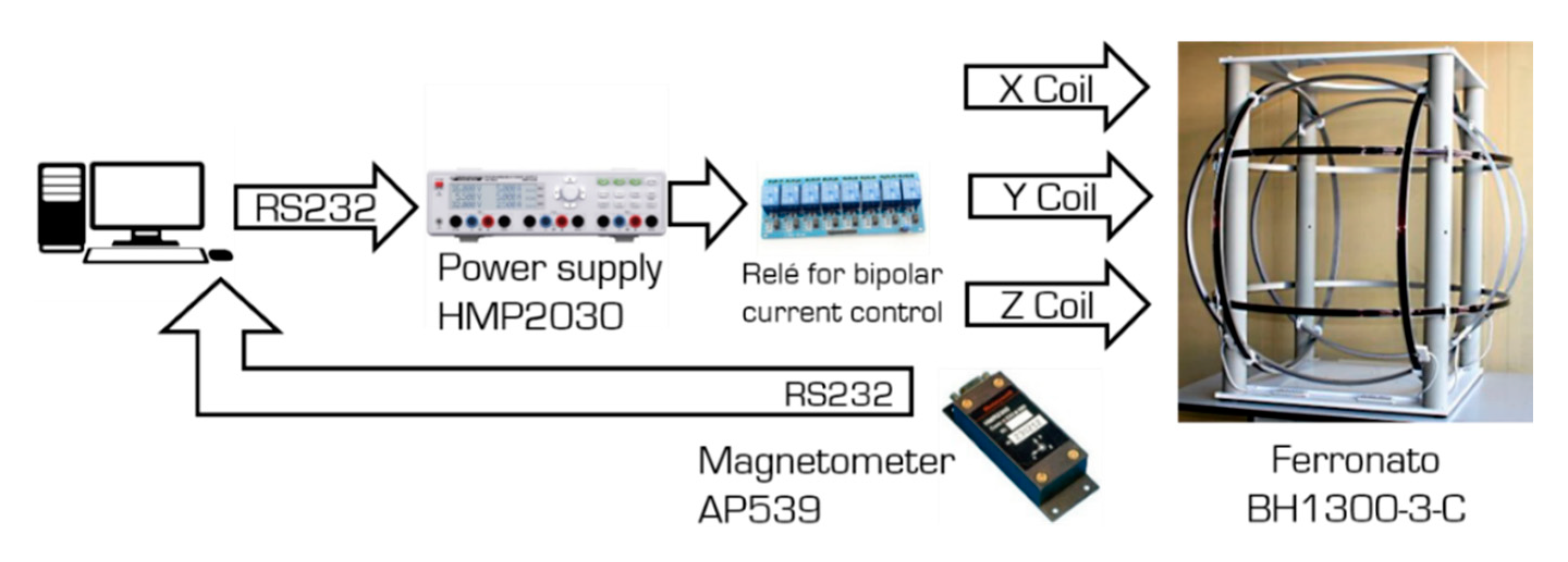
This commercially available of-the-shelf (COTS) equipment was customized for enhancing the accuracy when tracking a time-varying reference signal; this is, indeed, the main application scenario when testing a LEO satellite immersed in the geomagnetic field, which is experienced by the satellite as an almost periodic signal at the orbital period. To this end, a closed loop control was implemented, see
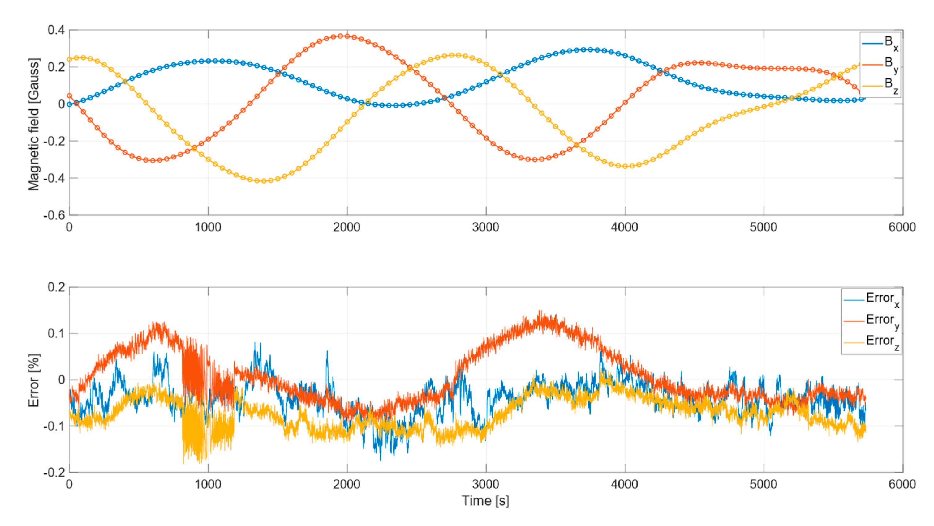
Figure 2, making use of a high-precision fluxgate magnetometer (AP539, from Applied Physics Systems, Mountain View, CA, USA), placed inside the pedestal support of the articulated stand. To test the effectiveness of the closed loop control, we simulated the geomagnetic field profile experienced by a spacecraft travelling on a circular orbit having 550 km of altitude and 70° of inclination. The magnetic field profile commanded to the Helmholtz cage was computed using the International geomagnetic reference field (IGRF) model: results are shown in
Figure 3. The feedback control allowed us to achieve a matching between the measured and commanded magnetic field below 0.2% (≈ 0.5 mGauss) along the three components
Bx,
By,
Bz. Furthermore, it also allowed to verify a-posteriori the homogeneity level stated by the manufacturer, which was indeed retrieved thorough a series of measurements gathered at random locations within the control volume.
Lying inside the Helmholtz cage, the air bearing articulated stand (Ferronato® ULTAS-1 from Serviciencia, Toledo, Spain) is intended to provide low-friction rotational motion. Purchasing the articulated stand from the same manufacturer of the Helmholtz cage ensured dimensional compatibility between the two, i.e., with the supporting platform of the articulated stand located in the middle of the region of highest magnetic field homogeneity.
The original COTS articulated stand, conceived for being balanced manually, has been customized by manufacturing a new rotational platform equipped with an automatic balancing system, designed to minimize the disturbance torque, as described in the next section.
3. Testbed Platform and Automatic Balancing System Design
The air bearing platform is aimed at supporting the nanosatellite mock-up, allowing a nearly torque-free rotational motion. The main disturbances affecting such systems are the aerodynamic torques from bearing and from the environment, anisoelastic torques arising from the platform, static and dynamic unbalance torques, and torques due to vibrations and electromagnetic interaction. Such torques must be limited, by design or by active systems, up to a magnitude possibly comparable to the level of disturbance torques expected in orbit. This, in turn, lies typically in the order of 10−6 Nm for a 3U CubeSat, which is an extremely low value to be matched in a ground-based facility.
Often, the largest disturbance is the unbalance torque due the distance between the centre of mass (CoM) and the centre of rotation (CoR). It can be cancelled only partially by design, and manual balancing does not lead to a guaranteed performance level [
21]. Several automatic mass balancing systems have been proposed in the literature [
28,
29,
36,
37,
43,
44], as they can largely reduce the time necessary for the platform tuning while ensuring repeatability, and a more effective reduction of the gravity torque. Even so, the stated disturbance limit for testing nanosatellites can hardly be reached: assuming a total rotating mass (platform with balancing mechanism plus CubeSat) in the order of 10 kg, a matching between the CoR and CoM shall be achieved up to 10 nm level, if we want a torque in the order of 10
−6 Nm. Such a value is well below the reported performance of existing automatic balancing systems. This suggests that substantial efforts must be devoted to platform balancing, and its effectiveness shall be verified a posteriori by estimating the residual torque acting on the balanced platform.
Furthermore, even if the static unbalance torque is successfully reduced, anisoelasticity gives origin to deformation of the platform which may lead to a consistent disturbance torque. The structural deformation of the rotating platform due to its own weight is difficult to compensate, since making a structure stiffer requires more weight, leading to a vicious cycle. As a countermeasure, an active compensation system was proposed in [
41]; nevertheless, efficient structural design remains a key approach to the problem, and it is also the one followed for our facility. In summary, platform design must account for two functional subsystems:
the mechanical structure, supporting the satellite and all the components necessary for the testbed operations, with minimal deformation torque;
the automatic balancing system (ABS).
3.1. Platform Mechanical Design
An aluminium tabletop platform has been selected as the most suited to satisfy the requirements, namely: (i) accommodate a nanosatellite mock-up plus ABS system equipment, while guaranteeing 3DoF with large rotations; (ii) limit the anisoelastic torque in the order of 10−6 Nm, and (iii) minimize the weight and inertia tensor.
Preliminary platform sizing was driven by analytical tools, using available results from the medium-thick axisymmetric plates theory [
45] to compute the plate deformation under the effect of its own weight, as a function of the thickness
h and tilt angle
.
The vertical displacement of a uniformly loaded axisymmetric plate of radius
R and flexural rigidity
D, as a function of the radial coordinate
, is governed by the following differential equation [
46]:
where
q is the load per unit area normal to the plate surface. In case of a plate subject to its own weight and tilted by an angle
:
,
being the material density and
g the gravitational constant. Once the boundary conditions are assigned, Equation (1) can be integrated analytically, leading to the deformation as a function of
r. From the deformation function, the displacement of the CoM,
can be computed. Then, the gravity torque due to sagging directly follows as the product between the weight
and the projection of the CoM displacement on the horizontal plane:
This way, the disturbance torque is related to the main design parameter, the thickness
h, and thus to the overall weight. Note that the maximum deflection
(hence
) is proportional to the ratio of the load over the flexural rigidity, according to [
45]:
with the proportionality constant
depending on the supporting condition of the plate, e.g., clamped or simply supported.
Results of this preliminary analysis indicated that a plate alone would get too thick and heavy before having enough stiffness, thus suggesting for a modified configuration. Nevertheless, plate theory also indicates that a plate with clamped edges, i.e., whose rotation is constrained, has a significantly lower bending than one with unconstrained edges (by a factor of about four), keeping all the rest equal. As a result, any structural element that prevents plate’s edge rotation, such as lateral walls, would reduce the maximum deformation.
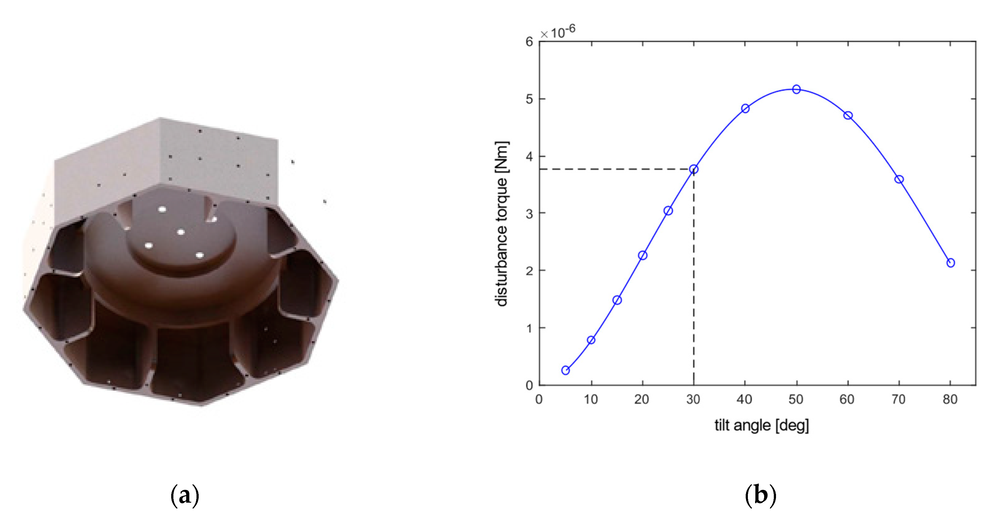
Following these considerations, the final design consists of a 12 mm thick octagonal plate with side walls featuring radial elements to enhance flexural stiffness, see
Figure 4a. The pattern of five holes in the innermost region allows for mounting on top of the semi-sphere of the spherical air bearing. The rationale behind the shape choice is a trade-off: ideally, an axisymmetric structure was to be preferred, for having isotropic inertia and stiffness about any axis of inclination. On the other hand, we needed a shape whose lateral walls allow to fix firmly the equipment needed for the automatic balancing system (the top surface is occupied by the nanosatellite mock-up). Therefore, we opted for a shape allowing for flat lateral surfaces while not departing too much from an axisymmetric one.
The total platform mass is about 4.5 kg. The maximum tilt angle allowed without interference with the stand pedestal is ≈30°.
3.2. FEM Analyses
The proposed design was then verified through FEM using Ansys
® software (Ansys, Canonsburg, PA, USA). Before analyzing the final layout, we checked the consistency of the modelling approach on a circular plate with clamped edges, whose maximum deflection was compared against the predictions from Equation (3), obtaining a match to within few percentage points. Then, a more representative geometry was analysed, starting from the CAD model of the octagonal platform, shown in
Figure 4a, with the holes removed. The geometry was then meshed using shell elements. The prescribed load conditions consisted of both a uniformly distributed load, simulating the platform’s own weight, and concentrated point masses. The latter aimed at accounting for the platform deformation due to the weight of the other equipment lying on it (see
Table 2). The boundary condition was prescribed as built-in along an inner edge having diameter equal to the one of the supporting semi-sphere.
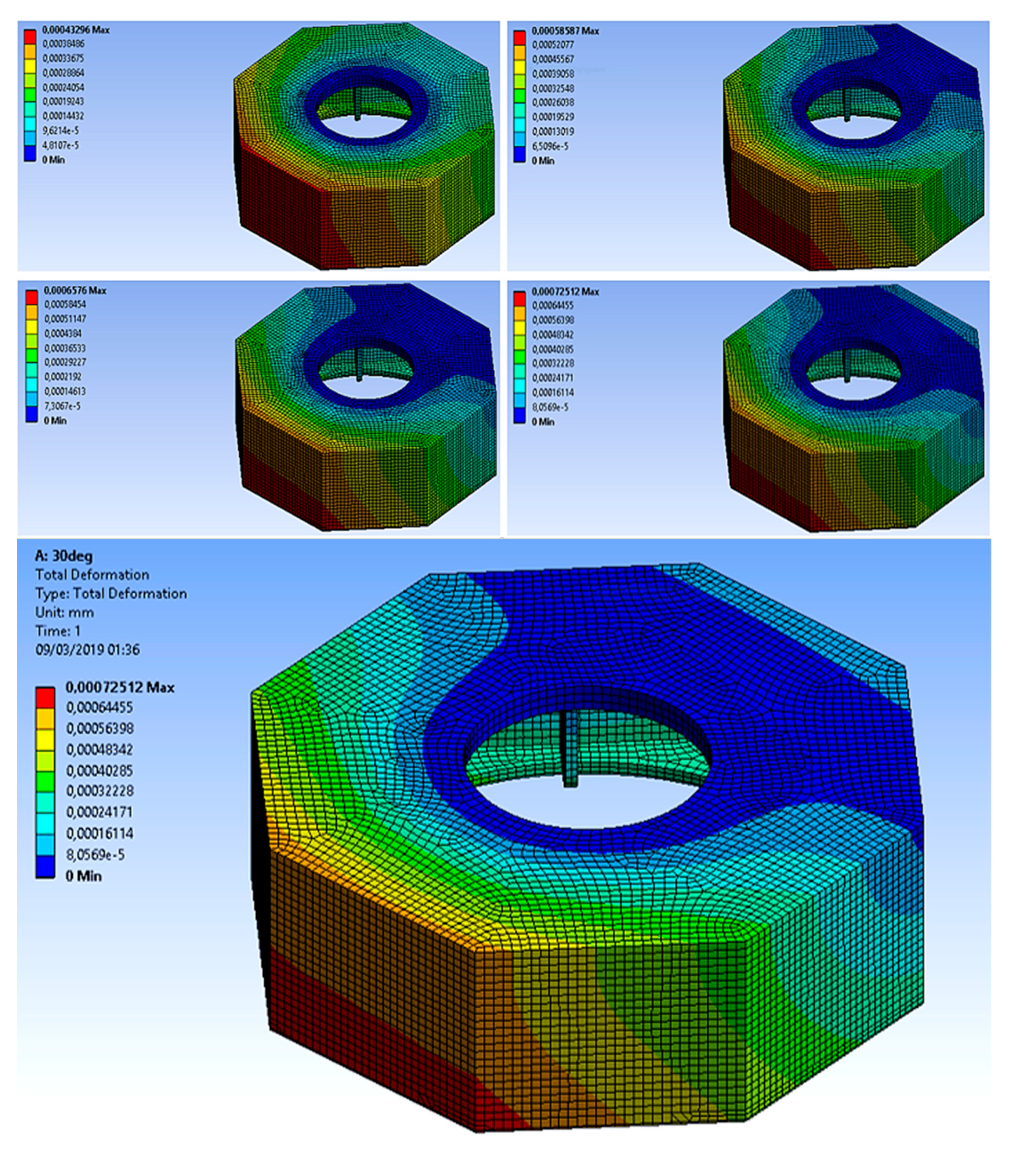
Simulations were repeated at various tilt angles, by rotating the direction of the load due to weight applied to the geometry. From the computed deformation (see
Figure 5), the new center of mass of the entire geometry can be located, which in turn allows to estimate the gravity torque.
Figure 4b summarizes the final outcome of this process, by displaying the FEM computed deformation, for eleven different tilt angles from 5° to 80°, along with an interpolant curve.
The magnitude of the anisoelastic disturbance is lower than at 30°, which is in line with the target requirement. Nevertheless, it clearly indicates that anisoelastic deformation is a source of non-negligible disturbance for our facility.
3.3. Automatic Mass Balancing System
The implemented ABS employs three sliding masses independently actuated by stepper motors along three orthogonal directions. Each balancing mass amounts to 0.11 kg and can be moved with a resolution of 0.002 mm by up to 15 cm (11 cm, for the vertically displacing mass). As a result, the ABS system can compensate a residual maximum unbalance of about 2 mm in magnitude for a 4 kg payload. Any possibly larger initial unbalance shall be compensated manually using counterweights.
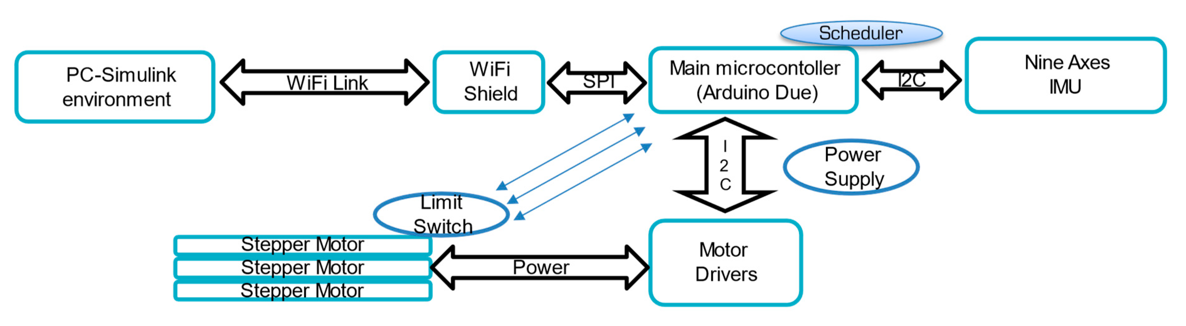
The motors are driven by an Arduino-based control system, powered by batteries (
Figure 6). The controller algorithms run on an Arduino Due board, which exchanges data with a PC server through a Wi-Fi connection. Attitude and angular rates measurements are provided by an inertial measurement unit (nine-axes motion shield, from Arduino, Turin, Italy).
The purpose of the system is to adjust the position of the shifting masses for driving to zero the offset vector from CoR to CoM, denoted as
. The procedure is iterative, towards increasingly finer balancing, with each iteration consisting of two steps. In the first step, a feedback control is employed aimed at aligning the platform normal to the local vertical direction (plane balancing). The underlying idea is to treat the plane balancing as an attitude control problem, where the control torque
is the one due to gravity, originated by the offset,
from the location of each mass
mb to the CoR [
37]:
Since this torque is physically confined in the direction perpendicular to the gravity vector
g, the feedback control can aim at compensating the unbalance existing on the same plane. To this end, we developed a projected nonlinear control law with integral action, adapted from the one proposed in [
46], to cope with the under-actuated scenario. In doing so, we obtain an admissible feedback, which lies on the horizontal plane, by projecting the feedback variables onto the same plane. Measurements required are the angular rates and the attitude, this last being made directly available by the IMU thanks to embedded filtering algorithms. The feedback control runs at a frequency of 20 Hz.
After the platform have been balanced in the horizontal plane (
), the second step consists of parameter identification from sampling of free platform oscillations [
47]. A least squares problem is formulated for estimating both the residual vertical unbalance,
, and the platform inertia parameters. The identified
is then compensated by moving the balance mass accordingly, and the overall process (plane balancing plus parameter identification) is repeated. Note that, in the following iterations, only the residual vertical offset
is estimated, assuming the inertia known. In our experiments, we verified that three automatic balancing iterations are usually enough for reaching convergence, i.e., to the point where no further reduction in the estimated residual offset is found.
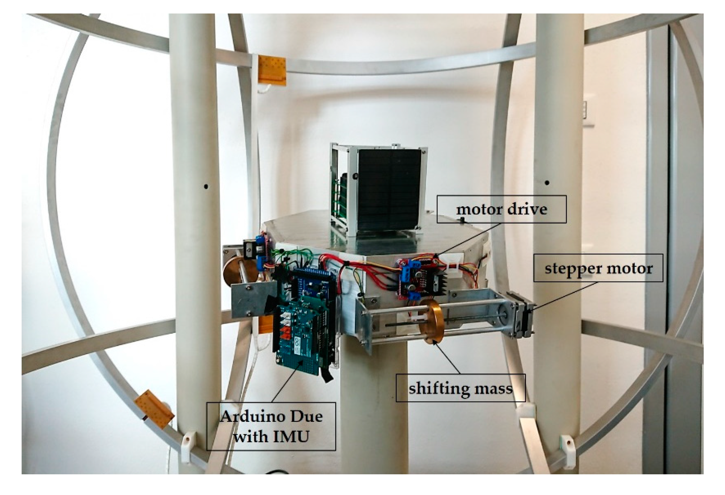
The effectiveness of the developed procedure for automatic balancing was tested experimentally on the platform equipped with the shifting masses and hosting a 1U CubeSat mock-up (10 × 10 × 10 cm size, ≈1.5 kg), as shown in
Figure 7. Experiments were performed according to the following steps:
Feedback compensation of and for plane balancing.
Sampling of free platform oscillations → estimate and inertia.
Relocate the vertical balancing mass to compensate identified .
Repeat point 1.
Sampling of free platform oscillation → estimate .
If return to 3, otherwise stop.
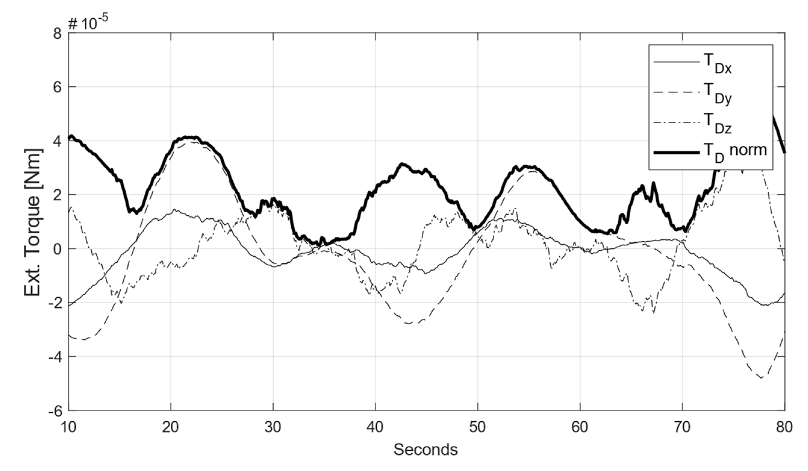
Once the balancing is completed, the residual disturbance torque,
TD, is estimated, again through the sampling of free platform oscillations, by computing the angular accelerations retrieved from differenced IMU measurements. A sample outcome from such evaluation is depicted in
Figure 8: the residual
TD is below 5 × 10
−5 Nm, with a root mean squared value of 2.5 × 10
−5 Nm, corresponding to a residual unbalance offset magnitude of less than 1 μm.
Despite being one order of magnitude higher than the typical disturbance expected for a CubeSat in LEO (≈10
−6 Nm), our result compares remarkably well with respect to the existing published data [
28,
29,
43,
44] (see
Table 3), especially when considering the extremely low cost of our implementation, i.e., less than 500 Euro for IMU, actuators, control electronics, and balance masses.
4. Sun Simulator
Since most LEO nanosatellites are equipped with Sun sensors, a Sun simulator was embedded in the facility, aimed at delivering a collimated light-beam resembling the sunlight. Derived from a COTS LED Studio light (Radiate D300, from Photonia, Bologna, Italy) with a 300 W phosphor-coated led as luminous source, the simulator has been equipped with a custom collimating Fresnel lens (ϕ = 400 mm). The distance of the Fresnel lens to the light source has been optimized for maximizing the beam collimation, through a dedicated test campaign.
Usually, a Sun simulator is classified according to three criteria, namely: (a) spectral matching, (b) spatial uniformity, and (c) temporal stability. For testing a Sun sensor, other parameters are of importance, such as the collimation of the light beam over a wide area, that shall be kept within 0.53°, i.e., the apparent angular diameter of the Sun at 1 A.U., and the power flux level (≈1367 W/m2 at 1 A.U.) at the nominal target distance (i.e., the distance from the LED source to the illuminated target, L ≈ 0.75 m in our case).
Most solar simulators make use of Xenon or metal halide discharge bulbs, which are known to deliver better spectral matching than LED sources. This is achieved, however, at the expense of a lower efficiency, lower lifetime, and a more complicated power supply needed to achieve a stable, flicker-free output. For our simulator, the choice of using a LED source was made, leveraging on its inherently flicker-free output, its high efficiency, and good matching in the visible part of the spectrum. The main drawback is the near absence of output in the IR and UV bands, so that spectral matching with the Sunlight is lost out of the visible band. This is not, however, considered a limiting factor in our application, as most existing nanosatellite Sun sensors are built upon CMOS, CCD, PSD, whose response is maximum within the visible band and falls-off rapidly in the IR and UV wavelengths. On the other hand, photocell-based coarse Sun sensors would be more affected by the lack of IR and UV bands simulation. Note that the response of these sensors is also altered by Earth albedo, which is anyway not modelled in the facility.
By using an LED source, one shall not aim at matching the overall solar irradiance since a consistent amount of the this is found in the IR and UV bands. Rather, the LED power has been chosen to match the extra-atmospheric solar illuminance (i.e., the photometric, visible-band flux density), which amounts to about 130,000 lux at 1 A.U. The target design parameters of the simulator are summarized in
Table 4.
Optimization and Verification of the Sun Simulator
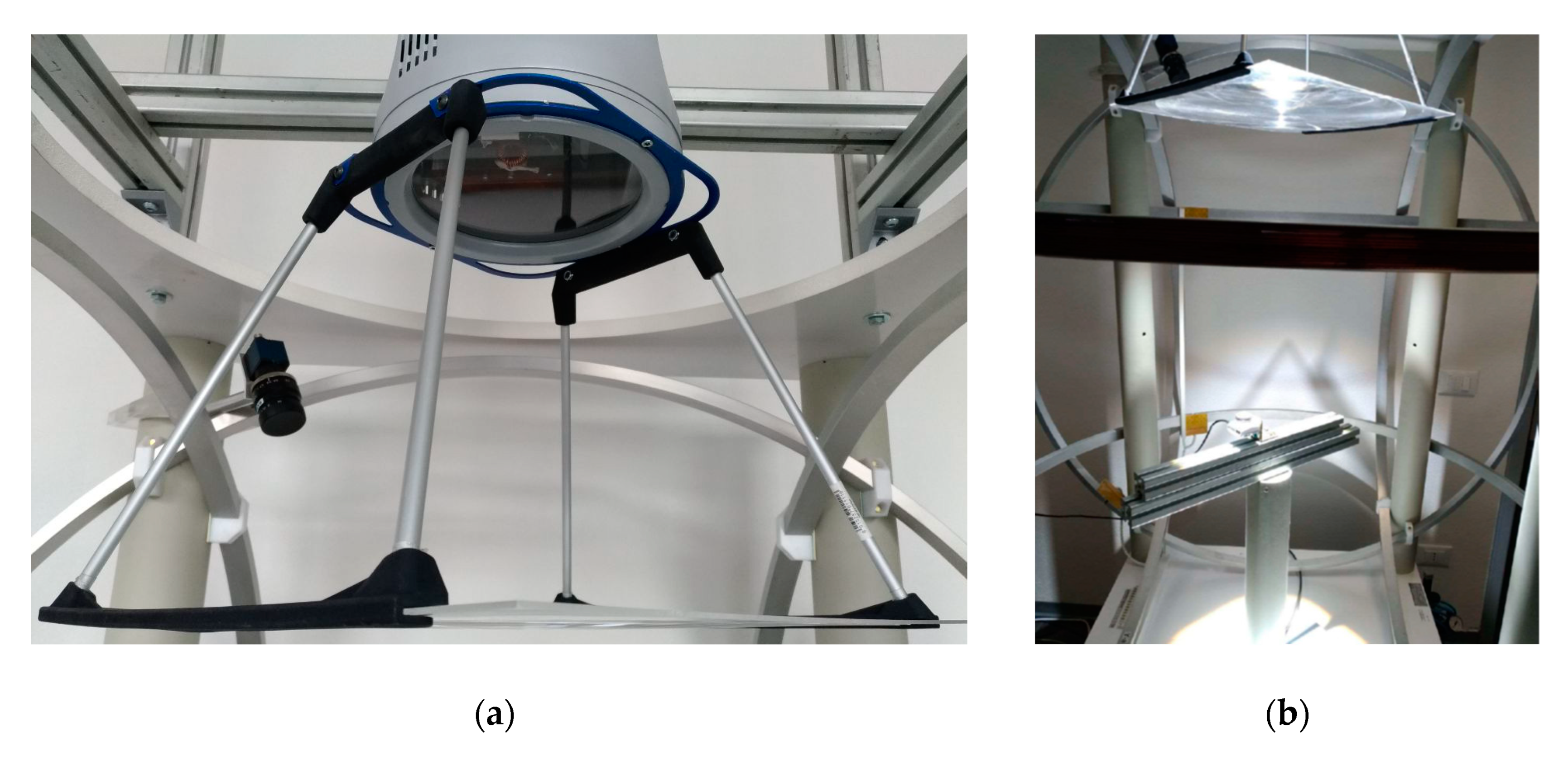
The core of the simulator is a COTS studio light whose primary intended use is not Sun simulation. The characteristics known from manufacturer are the type of LED used as a source, its CCT, and photometric data. Its design was thus customized for ensuring compliance with the main parameter of interest for our application, i.e., the beam collimation, by adding a Fresnel lens, see
Figure 9a. The validation of the custom design was performed in two steps: first, a test campaign was carried out for adjusting the distance between the Fresnel lens and the LED source to obtain the desired collimation level of the light beam. Then, a second test campaign was performed to assess the temporal stability and spatial uniformity of the collimated beam. Both test campaigns employed as a sensing device a 1.3 MPx monochromatic CMOS camera (EO-1312M 1/1.8”, Edmund Optics UK, York, UK) equipped with a small pinhole aperture. The use of a CMOS camera as a light-meter was justified after verifying that a linearity dependence exists between the Sun simulator dimmer level and the raw readings from the illuminated CMOS (provided that the camera exposure time is properly set to avoid saturation).
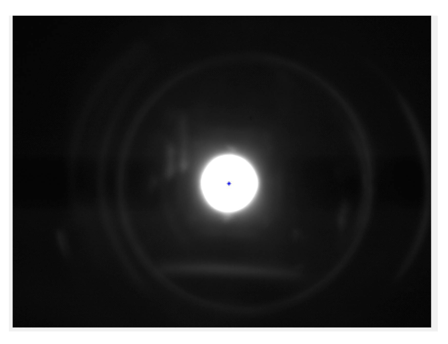
By varying the position of the sensor over the width of the light beam, the divergence could be estimated from the position of the centroid of the bright spot within the image (see
Figure 10), i.e., using the same working principle of pinhole Sun sensors [
48,
49]. During the experimental campaign, we also verified that the beam divergence is practically unaffected by variations of the working distance L of up to about 20 cm [
50].
The temporal and spatial uniformity at the working distance were later assessed by setting up a test-bench within the facility, see
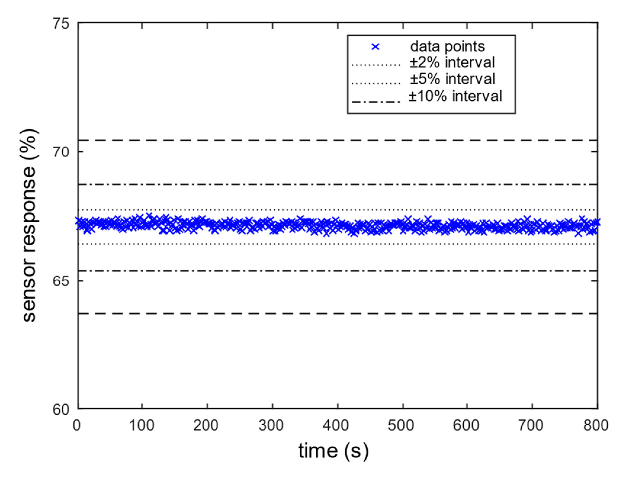
Figure 9b. Images were gathered by varying the camera location within the region of interest. For each image, the raw CMOS pixels intensity levels in the bright area were recorded. The variation is space and time of the average raw image intensity level was then used for evaluating the spatial and temporal stability, respectively.
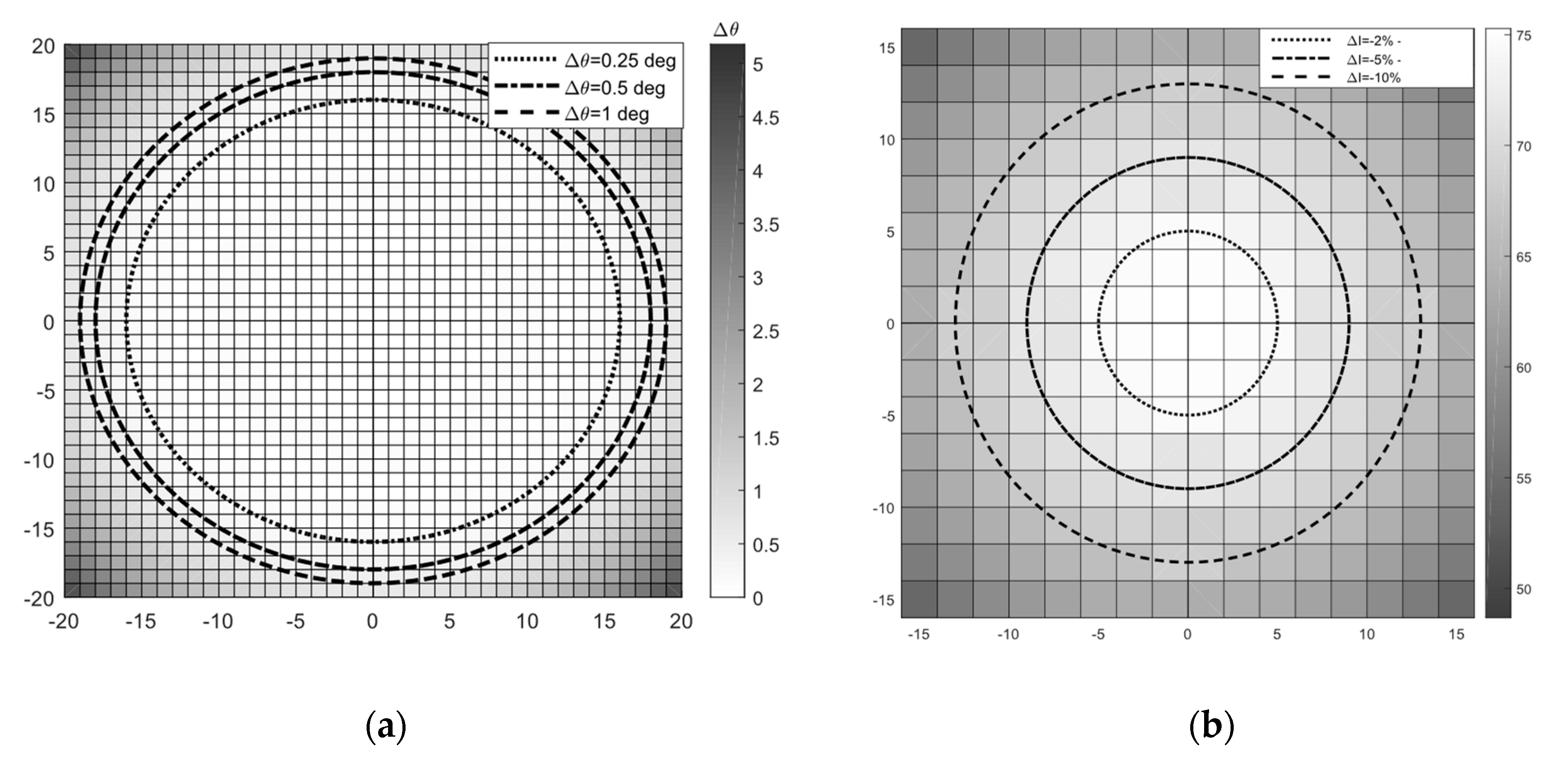
Figure 11 depicts results of the tests performed at the optimized lens-to-source distance: the beam divergence is kept below the 0.53° threshold within a 0.35 m diameter beam, thus meeting the requirement. Temporal fluctuations were found to be within 1% (
Figure 12), showing high stability, as expected for a led source. Spatial uniformity was found to be within 10% in a 0.25 m diameter region, which is slightly smaller with respect to the target beam size of 0.3 m.
5. Ground Truth Vision System
For validating the ADCS of a satellite through the dynamic testbed, independent ground truth data shall be available. To this end, a metrology system based on monocular camera vision has been developed. Despite having different degree of complexity, many similar applications were developed and published in the literature, e.g., [
21,
27], which use either a vision system or an inertial measurement unit (IMU) to determine the true orientation of the object under test. Using IMU in our case, however, would introduce further complexity on the test platform. This is a reason why a vision system has been preferred. The second reason lies in its potential accuracy. According to [
51], a vision system can reach accuracies down to 0.01–0.05°. Reported applications on air bearing systems such as the ones in [
27,
30], however, exhibit errors which are one order of magnitude larger.
5.1. System Implementation
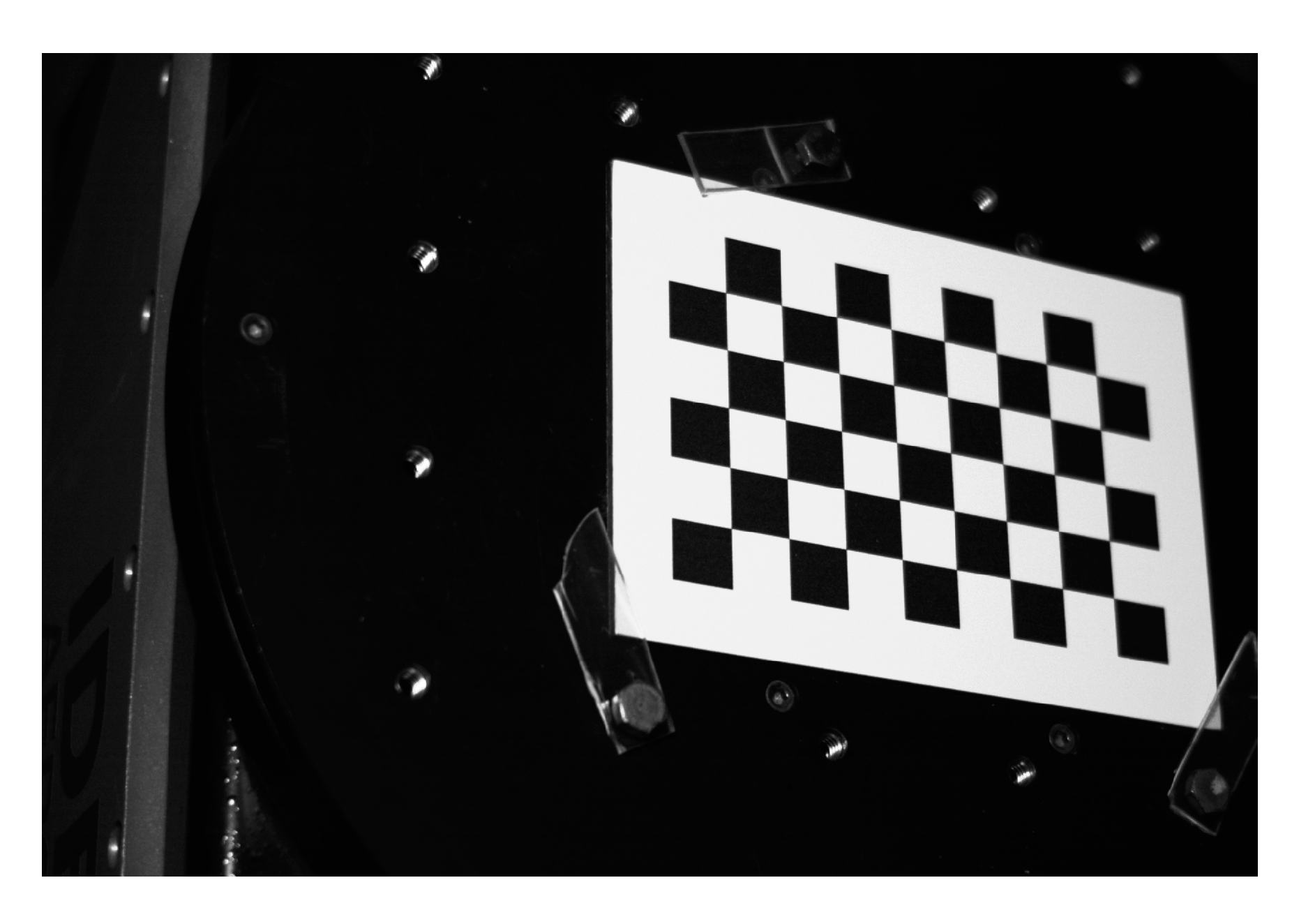
The working principle consists of placing a known visual pattern on top of the device under test, which is then imaged using a calibrated camera. Solving for the camera pose with respect to the target through corner points correspondences provides the attitude, which is retrieved as part of the pose solution. To this end, the required hardware consists simply of one camera, a calibrated target to track, and a computer for running the image acquisition and processing software. The camera used in our set-up is a 1920 × 1200 px, 41 fps, colour camera (MER-231-41U3C from Daheng, Beijing, China), and the calibrated target is a checkerboard printed on aluminium. The software for real time tracking of the target has been developed in house, making use of opensource vision and image processing libraries, namely the OpenCV 3.3.0 Library.
5.1.1. Calibration
Camera calibration is fundamental in photogrammetry since it allows to obtain the intrinsic camera matrix and to compensate for optical distortions. The calibration procedure works very similar to the tracking of a known checkerboard pattern described earlier, with the difference that here we are interested in estimating the camera intrinsic parameters rather than its pose.
For this work, we adopted the widespread calibration algorithm from [
52] and used the same checkerboard target. The checkerboard is placed at the operative distance from the camera, i.e., the average distance at which the tracked pattern is during real tests. Taking a dozen of images of this target in different positions inside the FoV, we obtained a calibration precision with 0.06 pixels of mean reprojection error.
5.1.2. The Computer Vision System
The computer vision system automatically analyses an image to obtain the relative attitude between the camera and the target checkerboard. The extraction/selection of the relevant information from recorded images is accomplished through a sequence of three steps [
53], namely: (i) feature detection, (ii) extraction, and (iii) matching. Features detection consists of finding the points of the image where corners appear (i.e., the checkerboard corners). The feature extraction task selects the detected features that satisfy a sharpness criterion to avoid unwanted features, such as corners from objects other than the checkerboard. Feature matching takes the extracted features and matches them to internal information to recognize desired objects, the checkerboard in our case.
Once the object is recognized, its tracking is performed by computing the optical flow, i.e., the pattern of relative motion between two subsequent imaged frames. In our work, the well-known Lucas–Kanade algorithm was adopted for corner tracking. Upon completion, the output of the image processing step is a set of corner points coordinates in camera frame. Since their coordinates are known also in the target frame (i.e., we know the size of the checkerboard), the pose of the object relative to the camera, hence the attitude, is retrieved by solving a Perspective-n-Point problem [
54].
The P-n-P is essentially a nonlinear least squares problem, which seeks for the camera pose minimizing the mean reprojection error of the corner points. The solution to this problem is tackled using a Levenberg-Marquardt iterative algorithm. This, in turn, requires a “good” initial camera pose guess for converge, which is, by default, set as the pose at the previous time step. In case of a dynamic environment, however, this approach may fail. To cope with fast dynamics, in our metrology system software the initial guess for pose estimation is instead computed from the prediction stage of a quaternion Kalman filter [
55] which provides both the attitude quaternion and the angular rate.
5.2. Experimental Verification
The monocular vision system was validated against an independent facility for extremely accurate angular motion simulation, available at a nearby laboratory. The facility is a 2 Degrees-of-Freedom (DoF) turntable (2102C, from Ideal Aerosmith, Grand Forks, ND, USA), capable to orient the test platform with an accuracy of 0.0083° and angular rates up to 50°/s. The outer axis implements lateral tilt, while the inner axis allows for unconstrained rotation around the normal to the turntable.
The experimental set-up consisted of the checkerboard target, tightly fixed onto the turntable test-rig as shown in
Figure 13. Test conditions were tailored to match as much as possible those encountered by the vision system when installed within the dynamic testbed: the camera was placed at the nominal working distance from the checkerboard, and a lamp reflector was employed to mimic Sunlight illumination. The tracked target was rotated randomly by the 2-DoF of the test rig, exploring a wide variety of orientations. Angular rates were prescribed up to 45°/s, to stress the performance of the vision system under severe dynamic conditions.
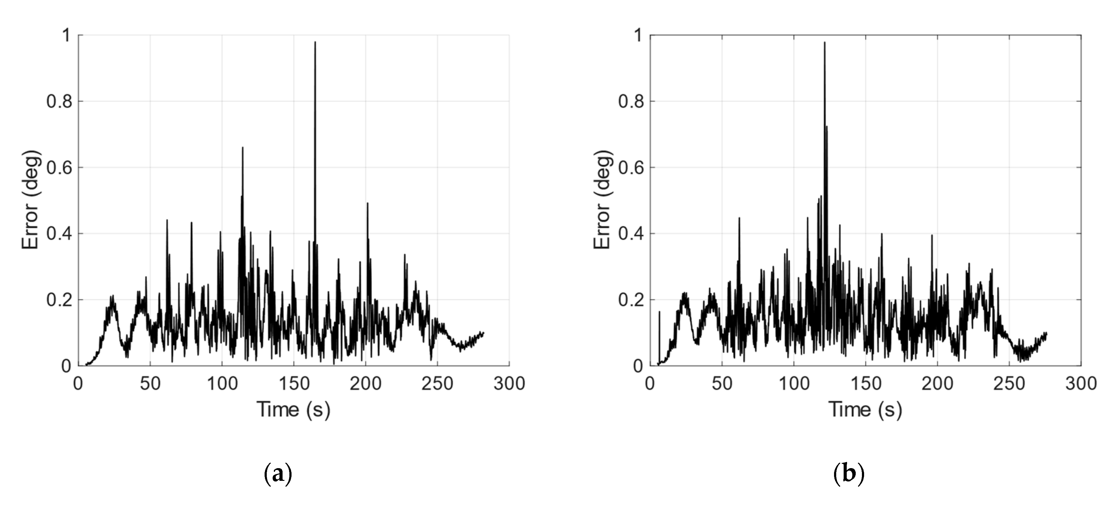
Attitude accuracy is obtained comparing the readings of the test rig to the output of the vision system.
Figure 14a,b depict the variation of the error as a function of the outer axis position, resulting from two experiments (with and without lamp illumination) gathering 5500 images each, at a frequency of 20 Hz.
Figure 14 and
Table 5 summarize the results: the system keeps the root mean square error below 0.16° (10 arcmin), regardless of the Sun simulator activity. This value is considered suitable for testing a mid-performance nanosatellite ADCS subsystem, but it is not enough for validating high-end ADCS targeting to, or below, the arcmin accuracy range. Nonetheless, it can be achieved with an extremely simple setup: one camera plus one checkerboard.
6. Discussion
A dynamic testbed for ADCS verification requires integration of various subsystems. Despite complete turn-key solutions do exist, in-house development may be preferred in some cases due to budget constraints. The drawback of such an approach is that a known performance level is hard to guarantee. In this paper, we outlined the design solutions, implementation steps, and verification strategy adopted during the development of such a facility at the University of Bologna. The testbed is built upon: (i) an air-bearing based, three degree of freedom rotating platform, (ii) a Helmholtz cage for geomagnetic field closed-loop simulation, (iii) a Sun simulator, and (iv) a metrology vision system for ground-truth attitude measurement.
Budget constraints led our design choices towards a low level of hardware complexity. This include, for example, employing a customized LED studio light rather than a COTS Sun simulator, and opting for a simpler monocular vision system, rather than a COTS multi-camera solution. In doing so, we kept the hardware cost of the entire facility below 20 kEuro (
Table 6), yet obtaining adequate performances. These were achieved, in turn, by developing: (a) a custom designed rotating platform for reduced structural deformation; (b) an automatic balancing system with a posteriori experimental verification of the disturbance torque after balancing; (c) a collimation system for the LED simulator, whose divergence and spatial uniformity have been experimentally verified; (d) a custom monocular vision system for ground truth attitude-generation, validated under dynamic conditions against a highly accurate turntable.
Results after the commissioning phase demonstrated that our testbed achieves: (1) a residual disturbance acting on the rotating platform after balancing of less than 5 × 10
−5 Nm (
Figure 8); (2) divergence of the Sun simulator light beam of less than 0.5°, spatial stability under 10% (
Figure 11), and temporal fluctuations below 1% (
Figure 12); (3) an attitude determination accuracy of the ground-truth, monocular metrology system less than 10 arcmin rms (
Figure 14).
The facility is quite flexible in terms of ADCS application testability, as it can host nanosatellite mock-ups of different sizes and control modes (such as zero momentum, momentum bias, spinning bus) while allowing for variable sunlight and magnetic field intensity. The first application, namely the verification and testing of a CubeSat mock-up for validating magnetic-based attitude control techniques, is about to start. Nevertheless, the testbed development is considered an ongoing process. Foreseeable enhancements include the integration of a smaller air bearing for 1U CubeSat verification and of a starry sky simulator for star-trackers verification.


