Control of a Supersonic Inlet in Off-Design Conditions with Plasma Actuators and Bleed


Politecnico di Torino, Corso Duca Degli Abruzzi 24, 10129 Torino, Italy
Aerospace 2020, 7(3), 32; https://doi.org/10.3390/aerospace7030032
Submission received: 17 February 2020
/
Revised: 13 March 2020
/
Accepted: 16 March 2020
/
Published: 19 March 2020
(This article belongs to the Special Issue Control and Optimization Problems in Aerospace Engineering)
Abstract
:Supersonic inlets are a key component of present and future air-breathing propulsion systems for high-speed flight. The inlet design is challenging because of several phenomena that must be taken under control: shock waves, boundary layer separation and unsteadiness. Furthermore, the intensity of these phenomena is strongly influenced by the working conditions and so active control systems can be particularly useful in off-design conditions. In this work, a mixed compression supersonic inlet with a double wedge ramp is considered. The flow field was numerically investigated at different values of Mach number. The simulations show that large separations appear at the higher Mach numbers on both the upper and lower walls of the duct. In order to improve the performances of the inlet two different control strategies were investigated: plasma actuators and bleed. Different locations of the plasma actuator are considered in order to also apply this technology to configurations with a diverter which prevents boundary layer ingestion. The potential of the proposed solutions is investigated in terms of total pressure recovery, flow distortion and power consumption.
1. Introduction
Supersonic intakes represent a critical component of supersonic vehicles since they can strongly influence the performances of the engine [1]. The flow field inside the intake is governed by strongly non-linear phenomena, like shock waves and turbulence. The interaction between shocks and boundary layers can lead to separations, which are responsible for large total pressure losses and unsteady phenomena which represent dangerous dynamic loads for the structure.
Furthermore, the growing interest in hypersonic flight leads to even more challenging scenarios in which the intake is subjected to extreme working conditions [2]. In SCRAMJET engines, for example, the intake is used to decelerate the incoming hypersonic flow by means of oblique shock waves that can lead to dangerous shock–shock interactions in the vicinity of the engine cowling [3]: this leads to very high heat fluxes through the intake structure.
Several research studies have been devoted to the design of supersonic intakes, with particular attention given to mixed-compression configurations. The typical goals that drive the design include total pressure recovery, uniformity of the flow, mass flow, spillage drag and cowl wave drag. In order to compromise between these objectives, several geometries were investigated. Some examples are represented by multiple ramps [4,5,6], three-dimensional bumps [7], combinations of ramps and cone [8], combinations of wedges and smooth ramps [9].
Another important feature that defines the quality of an intake is represented by its ability to maintain good performance in off-design conditions. This is a key point since the intake should be able to work from low speed sea level conditions to high speed altitude conditions. When the flight Mach number is changed, the shock structure in the inlet evolves. The interaction between shock waves and boundary layers can lead to large separations whose extension is strongly influenced by the working conditions.
In order to improve the off-design performances, several strategies can be adopted [10]. Some passive control approaches can be adopted in order to limit the effects of the flight Mach number, like for example the use of cavities with porous surfaces [11,12,13,14]. Alternatively, several active control systems are available. A straightforward approach consists of using a variable geometry intake: this solution was, for example, adopted in the Concorde aircraft in which variable angle ramps were employed; this solution was also investigated for hypersonic vehicles [15]. Shape-memory alloys were proposed for variable geometry ramps, both as actuators [16] and shape morphing devices [17].
Boundary layer bleed is another widely used active control strategy [18]: the separation induced by shock–boundary layer interaction can be significantly reduced by removing air from a slot, a scoop or by means of distributed suction. This technique is very effective but introduces a bleed drag contribution, which can represent a significant contribution to the total vehicle drag.
Some studies were performed on the possibility of controlling the flow by an off-body energy addition [19,20]. Alternatively, several research efforts have been devoted to the development of plasma actuators in which the air close to the wall is locally ionized by an electrical discharge [21,22,23,24,25,26,27]. This technology was also investigated for controlling flow separation in rocket nozzles for space launchers [28]. In the experimental work performed by Falempin et al. [25] a quasi-direct current discharge is applied on the wall in front of a double wedge inlet ramp in off-design conditions: the activation of the plasma actuator generates a perturbation in the flow which is able to steer the leading edge shock wave in order to improve performances in off-design conditions. The experimental study was followed by a computational fluid dynamics (CFD) analysis in which the effects of the plasma actuator are reproduced by introducing a volumetric heat source close to the wall.
In the present work the flow inside a double wedge supersonic inlet was investigated by means of numerical simulations. After the first validation and comparison with the available experimental results at Mach number , two off-design working conditions ( and ) were considered. Since the uncontrolled flow shows large separations, a study on the potential improvements obtained by introducing a plasma actuator eventually supported by a bleed system was performed. Several locations of the plasma actuator were investigated and the performances in terms of total pressure recovery, flow distortion and power consumption are provided.
2. Physical Model
2.1. Compressible Reynolds-Averaged Navier–Stokes (RANS) Equations
In this work, the flow in a supersonic planar intake is described by the 2D compressible Reynolds-averaged Navier–Stokes (RANS) equations with the Spalart–Allmaras (SA) turbulence closure [29], which are reported in the following:
where , , p, E, , , and t are density, velocity, pressure, total energy per unit volume, molecular viscosity, modified eddy viscosity, spatial position and time, respectively. An ideal fluid is considered with frozen chemical composition and constant viscosity and heat capacity. The following state equation is considered:
where is the specific heat ratio, here set to 1.4. The Prandtl number is set to 0.72.
The diffusive effects are represented by the viscous stress tensor and heat flux which contain both the molecular and turbulent contributions.
The SA model was chosen for this work because in the considered test case it provides results which are in the range spanned by more complex turbulence models (like for example the SST [30] or the [31]) as will be shown in Section 5. Furthermore, the SA model was succesfully used in the simulation of aerospace propulsion systems [32] and can be augmented by data-driven corrections to improve its predictive ability [33]. The inlet boundary condition for the SA model is set to , according to the recommendations of Spalart and Rumsey [34] for high Reynolds number flows.
The performance indexes which are used to evaluate the different control techniques and is defined in Section 6 are based on time-averaged quantities: for this reason steady RANS simulations are performed in this work. It is possible to use unsteady RANS approaches to study some unsteady phenomena in supersonic inlets [35]: an example is represented by the inlet buzz which is observed when the inlet operates in a subcritical regime [36]. However, the present work is focused on the performances of a started inlet in off-design conditions and so the buzz phenomenon is not investigated here but only the average fields in the started inlet are required. In the literature it is possible to find some examples of large eddy simulations (LES) [37,38] and hybrid RANS-LES simulations [39,40]: these approaches can give a more detailed description of the turbulence phenomena that take place inside the inlet with respect to RANS models and so they can give a more accurate prediction of the inlet performance. However, they have mainly been adopted for studying the buzz in the subcritical regime and the starting transient of the inlet. The Reynolds number of the inlet studied in this work is so high that a wall resolved LES would require a prohibitive cost, especially for a parametric study in which several configurations are investigated. Hybrid RANS-LES approaches would have a more affordable computational cost but they rely on RANS models in the boundary layer and so they are still affected by the model uncertainty that characterizes RANS simulations. For these reasons, the steady RANS approach is adopted in this work since the goal is to compute the average field in the supercritical regime and to investigate the effects related to the location of the plasma actuator.
2.2. Plasma Actuator Model
The last term s in Equation (3) is a volumetric heat source which represents the main effect of a quasi-direct current plasma actuator according to Falempin et al. [25]: they describe the plasma region with a sequence of plasma filaments very close to each other. In their simulation, each filament is represented by a heat source with a length and diameter of 22 1.5 mm, respectively. Since in [25] a power of 6.5 kW is distributed among 11 of these filaments, an average power density W/m is estimated. While in [25] the actuators were described in a 3D simulation, in the present work a 2D approximation was adopted: the heat source was here activated only in a rectangular region close to the wall. The aspect ratio of the rectangle is set to 14.67 according to the length and diameter of the filaments observed by [25].
In the configuration considered in this work, the actuators were assumed able to generate a plasma region with a length of 10 mm: this means that the required power per unit depth is 102 kW/m.
The goal of this work is to verify the potential of the proposed technology. The chosen modelization represents a significant approximation of the physics but is able to reproduce the main effects of this kind of actuators, as shown by [25]: if the results of this preliminary study are judged promising then more complex physical models should be considered to verify the electric tension required to induce the discharge in the chosen working conditions. A review of more complex physical models is available in the book by Shang [41].
3. Numerical Discretization
The governing equations are discretized by means of an unstructured solver which is based on the method of lines: a finite volume discretization is adopted in space while time integration is performed by means of the linearized implicit Euler scheme. The solver, which can be use in both finite volume or discontinuous Galerkin mode, has been verified and validated on compressible inviscid flows [42,43], laminar flows [44] and turbulent flows [45,46,47,48,49,50].
The convective terms are computed by the AUSM+ scheme [51] combined with a second order accurate reconstruction obtained by the application of the Barth–Jespersen limiter [52]. The gradients required by the viscous fluxes and source terms are evaluated by means of a weighted least squares approach. The parallelization in the message passing interface environment is managed through the DMPlex class [53] provided by the PETSc library [54].
4. Inlet Geometry
A double wedge inlet followed by an isolator duct is considered in this work. The isolator consists of a nearly parallel walled duct that separates the inlet and the combustor of a dual-mode SCRAMJET: the purpose of the isolator is to provide a stable flow to the combustor for different working conditions [57].
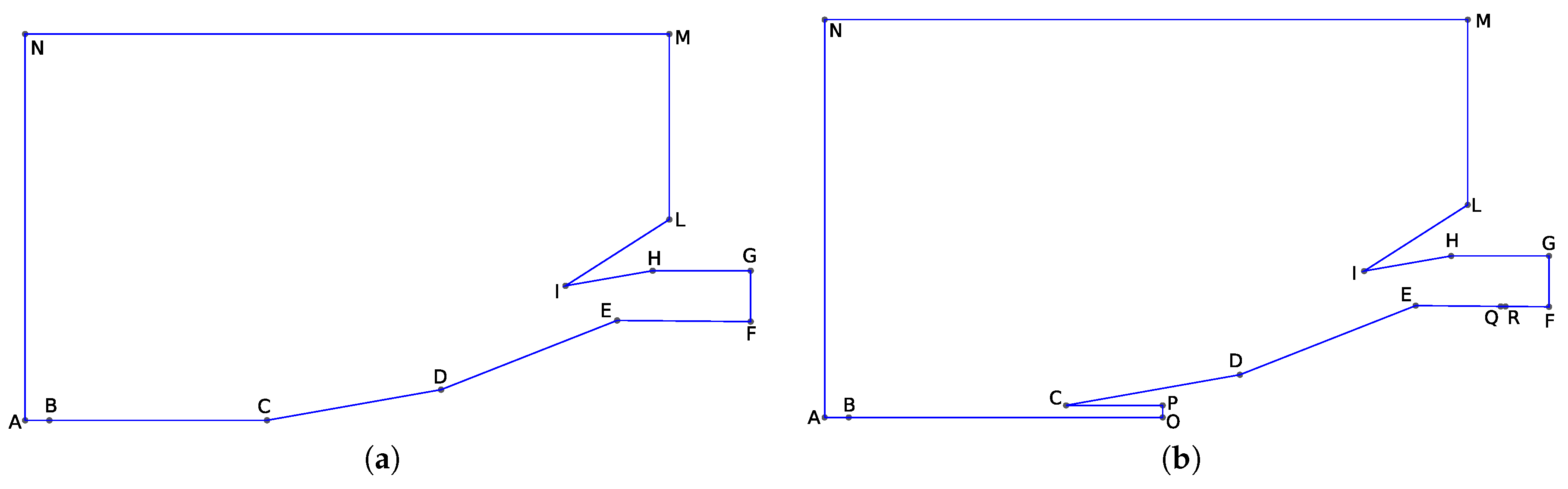
In particular, the geometry, which is identified as Model V-CC in the experimental work of [58], is taken as reference. A scheme of this geometry is reported in Figure 1a. The original setup studied by Schneider and Koschel [58] did not allow us to simulate the incoming boundary layer generated by the forebody. In this work, several configurations were considered in order to simulate the ingestion of the incoming boundary layer and the presence of a diverter between the inlet and the fuselage. For this reason, two different geometric configurations (A and B) were considered and reported in Figure 1. In particular, configuration B shows a diverter, which prevents the boundary layer on the fuselage, to be ingested in the intake: this is obtained by shifting the intake with respect to the fuselage. This last configuration is adopted in several aircraft [1].
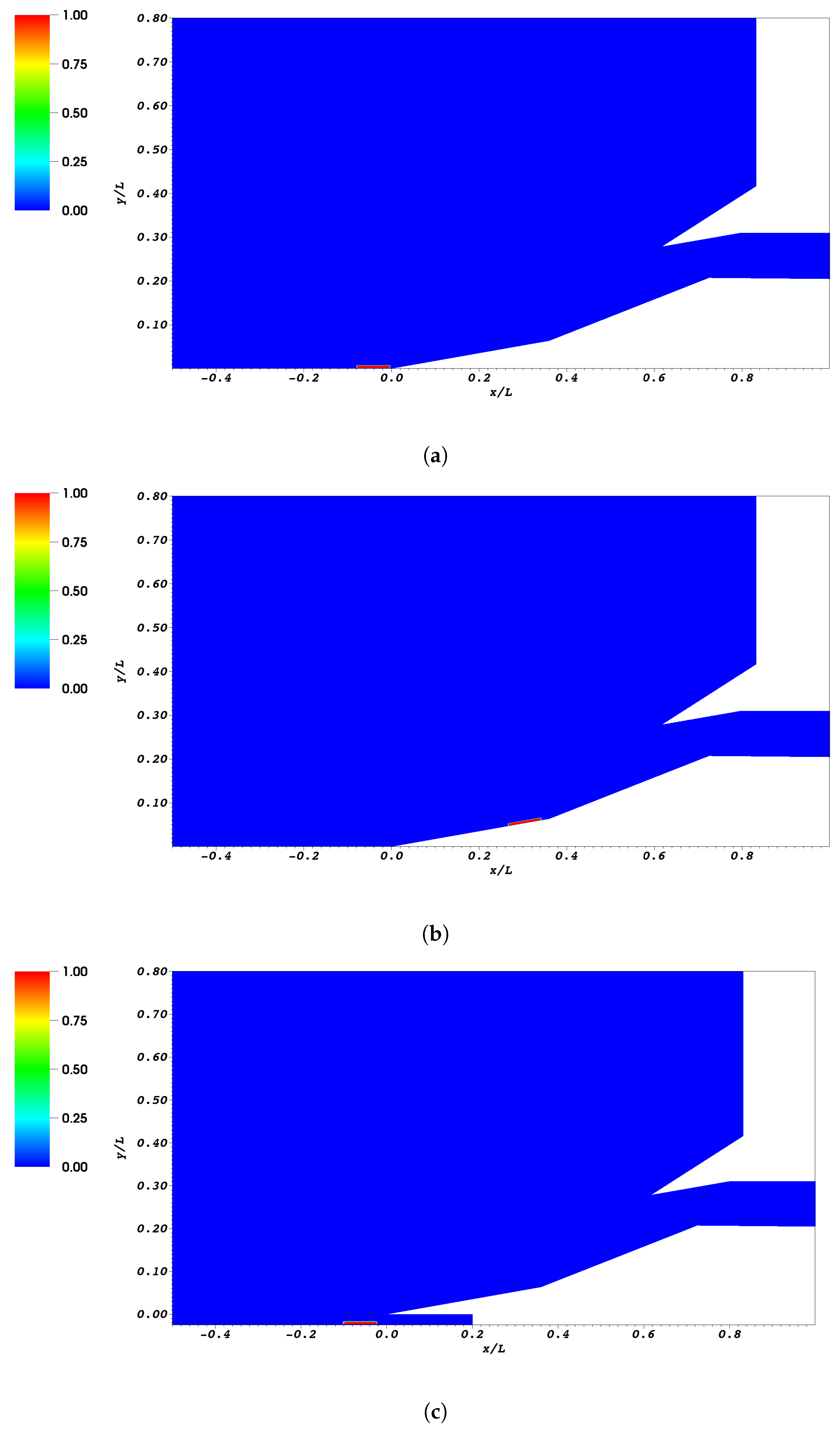
The coordinates of the points which define the geometries for the configurations A and B are reported in Table 1 and Table 2, respectively. All the coordinates are normalized with respect to the axial length of the configuration A ( mm). The boundary conditions for the different configurations are reported in Table 3 and Table 4. While the walls of the wedges, lip and isolator are always described as solid walls (no slip adiabatic condition), the segment BC which appears in the configuration A can be assigned to both the symmetry or the solid wall boundary condition: in the first case there is no boundary layer ingestion, and in the second case it is possible to simulate an incoming boundary layer. This freedom makes it possible to evaluate different locations of the plasma actuator that are reported in Figure 2, which shows the thermal source term related to the plasma actuator. In particular, three locations were investigated: the actuator in front of the first ramp shown in Figure 2a (configuration A, segment BC is a solid wall), the actuator in front of the second ramp shown in Figure 2b (configuration A, segment BC is a symmetry boundary) and the actautor on the fuselage Figure 2c (configuration B with diverter).
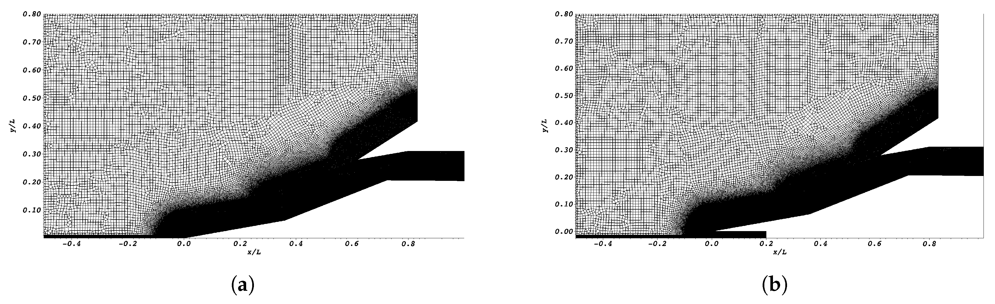
Finally, in Figure 3 an example of meshes for the two configurations is reported: the mesh is unstructured with a structured region close to the walls. The size of the elements is controlled by means of attractors based on the distance from the walls.
5. Validation at
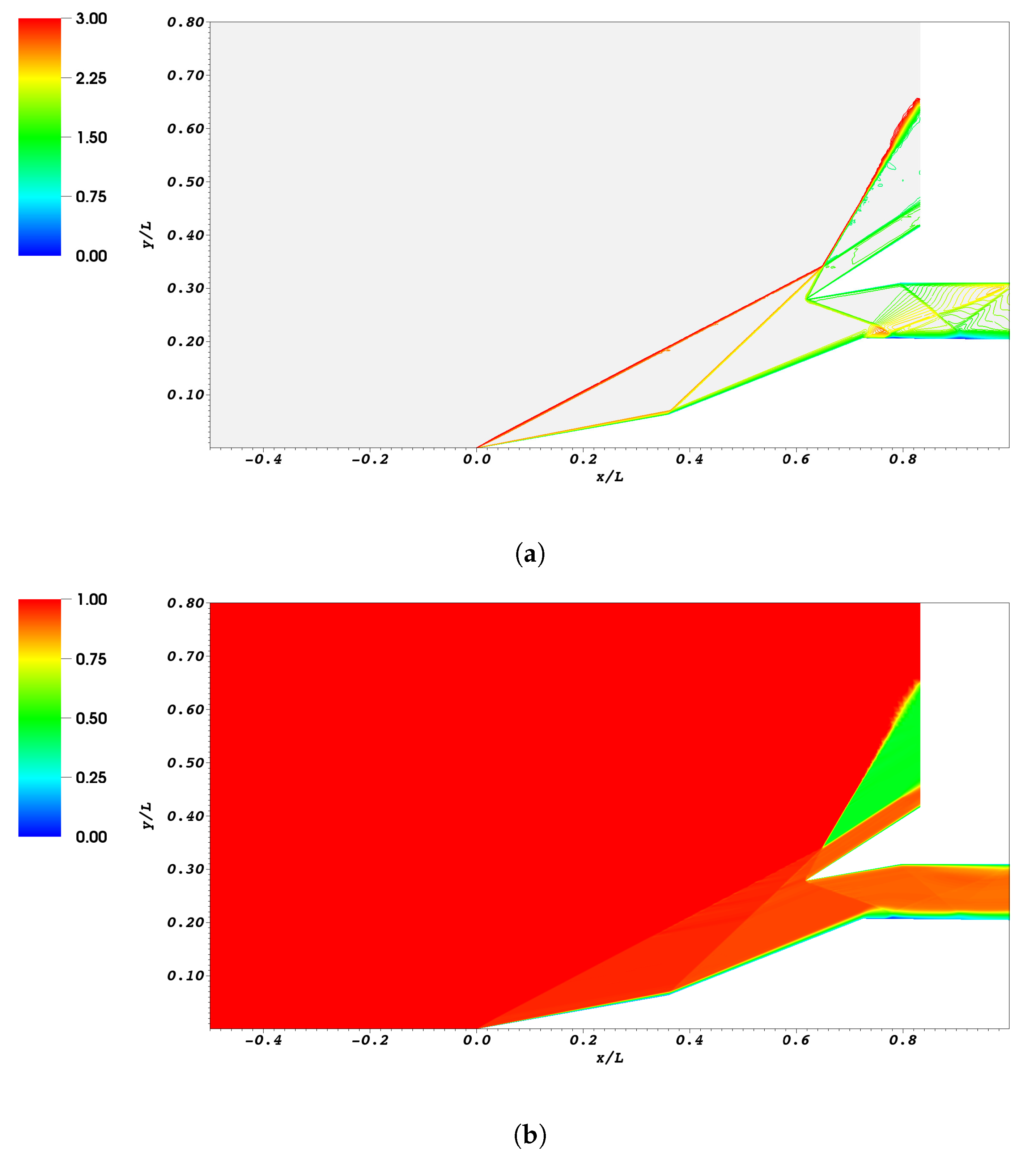
A preliminary study was performed on the double wedge inlet described by the configuration A with a symmetry boundary condition in the segment BC (see Figure 1a): this means that there was no boundary layer ingestion and so the configuration was in line with the experimental setup described by [58]. In order to validate the numerical approach the inlet was studied with a freestream Mach number and a Reynolds number . These working conditions correspond to the experimental conditions adopted in [58]. The Reynolds number is here referring to the axial length of the first ramp (46.73 mm).
In Figure 4, the Mach number and total pressure fields obtained by the numerical simulation are reported: the picture shows the different shock waves and their interactions. The reported total pressure field is normalized with respect to the far field total pressure. The coordinates in the picture are normalized with respect to the axial length L (from the leading edge of the first ramp to the end of the inlet channel), previously defined.
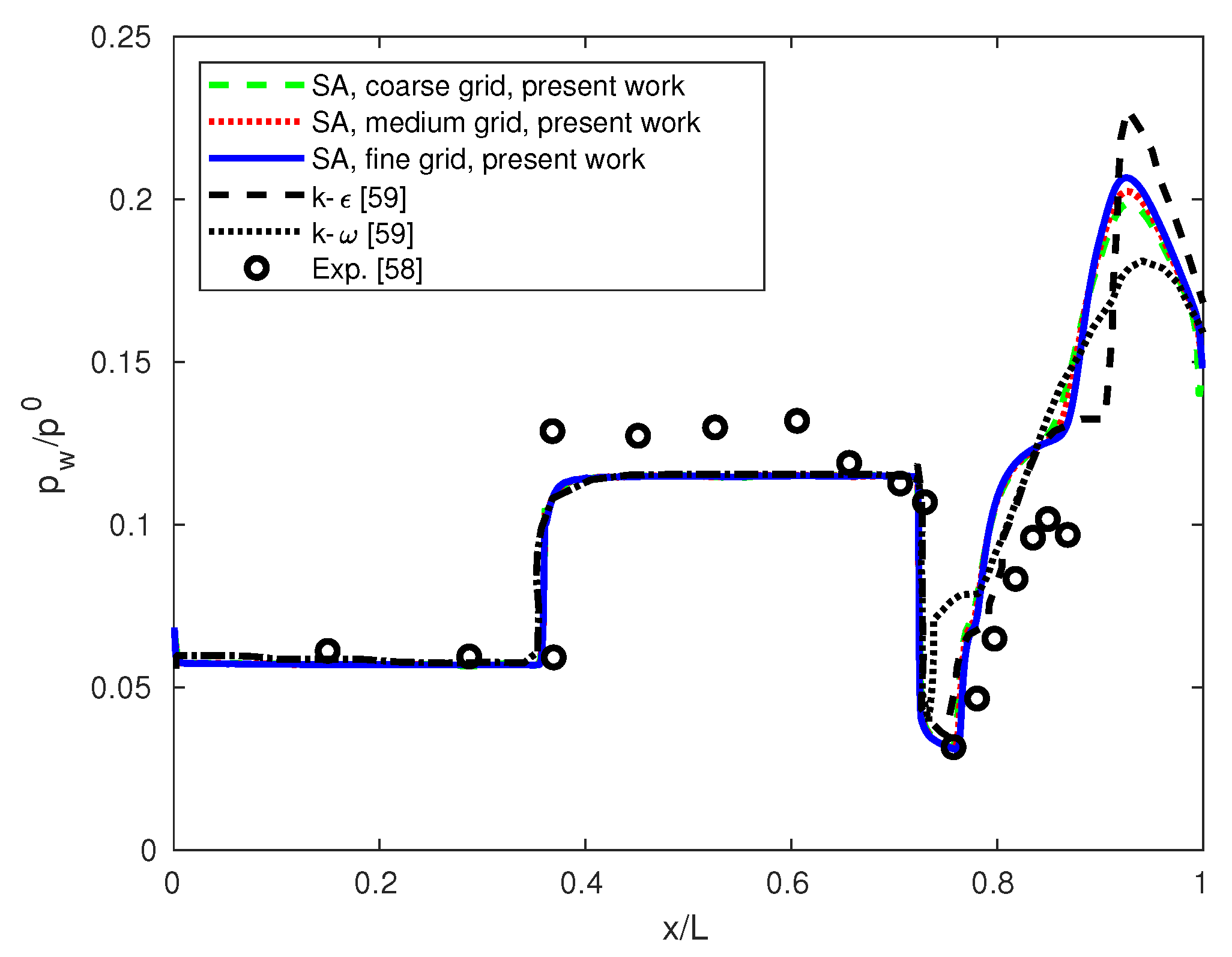
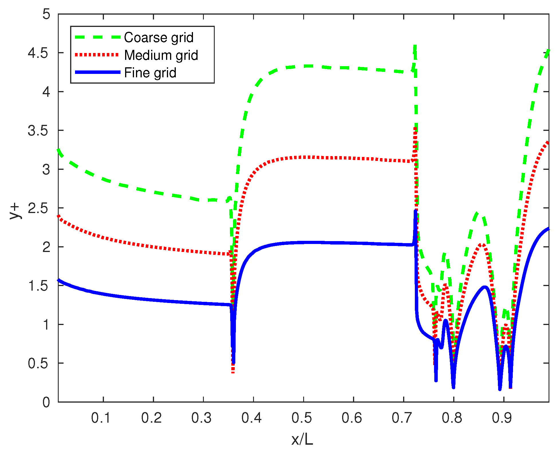
First of all, a grid convergence analysis was performed in order to define the minimum resolution requirements. Three different meshes with 52,723, 83,847 and 16,6281 cells were considered. In Figure 5 the wall pressure distribution normalized with respect to the far field total pressure is reported. The plot shows a comparison between the experimental results from [58], the present numerical results and the numerical results obtained with the SST [30] and [31] models by [59]. All the numerical simulations tend to underestimate the pressure on the second ramp but they are very close to each other. In contrast, the solution after the expansion fan is quite affected by the choice of the closure model. The present results obtained by the SA model are in the range spanned by the SST and models. In Figure 6 the dimensionless wall distance distribution is reported for the different meshes: the finest mesh is characterized by for almost all the points close to the wall. The size of the first cells in the wall normal direction is . This satisfies the recommendations for the Spalart–Allmaras model, which suggest introducing at least one point in the viscous sublayer (). The sensitivity of the results to the mesh resolution shown in Figure 5 is considered sufficiently small for the finest mesh: the finest resolution level is adopted for all the following simulations.
6. Off-Design Study at
6.1. Uncontrolled Case at
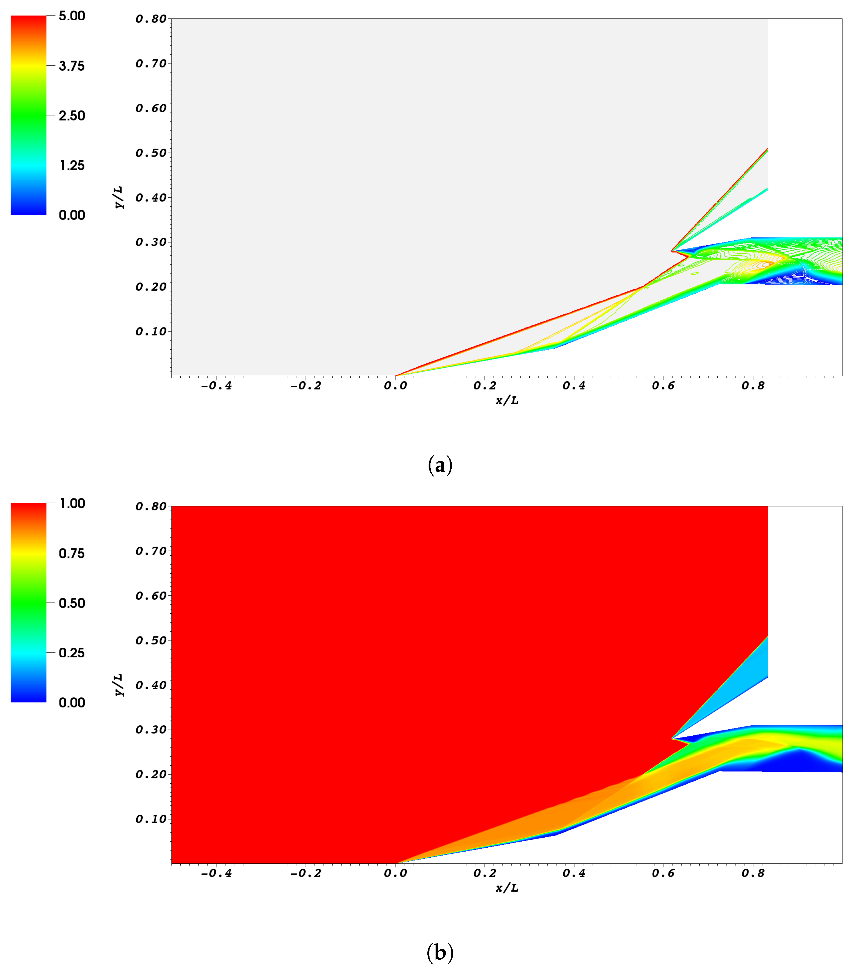
The behavior of the inlet was investigated in an off-design condition at on the geometric configuration A (a symmetry condition was assigned to segment BC and so there was no boundary layer ingestion). The Mach field and the normalized total pressure field in this condition are reported in Figure 7. The picture shows two separations: a small separation on the upper wall of the channel near the lip and a large separation on the lower wall induced by the reflected shock waves. The presence of such separations represents a significant limitation to the possibility of using this inlet in this working condition because of large losses in total pressure and unsteady effects which are related to the high turbulence level which characterizes the separated region. In order to quantify the performances of the inlet the following performance indexes are defined:
where R is the recovery coefficient and is a standard deviation which measures the flow distortion. Both quantities are referred to the mass-averaged total pressure at the end of the inlet:
where h represents the height of the channel at the end of the inlet. These parameters represent a common choice for evaluating the performances of supersonic inlets [7,60].
6.2. Plasma Actuator in Front of the First Wedge at
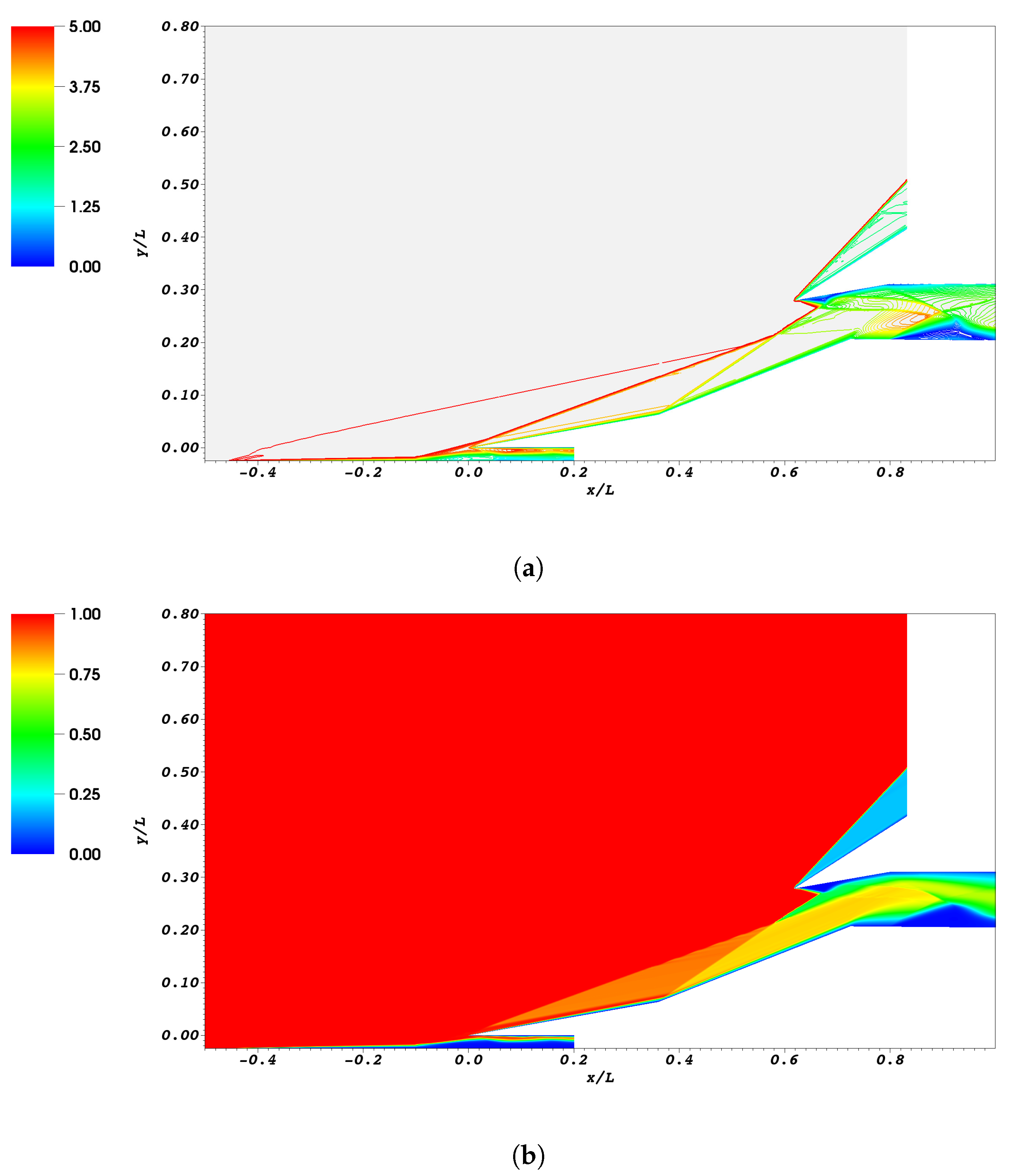
The performances of the inlet in the uncontrolled case and with several control strategies are reported in Table 5. In order to improve the performances, the control strategy proposed by [24,25] was introduced: a plasma actuator was activated in front of the leading edge of the first ramp. This configuration requires the presence of a solid wall in front of the inlet: for this reason, the configuration A with a solid wall boundary condition for the segment BC (see Figure 1) was considered.
The thermal power source field, normalized with respect to , is reported in Figure 2a. A comparison of the Mach field between the uncontrolled case (Figure 7a) and the controlled case (Figure 8a) clearly shows the effects of the actuator: the injected thermal power induces the thickening of the boundary layer, which is responsible for a displacement of the shock waves. As a result, the shock waves from the two wedges do not enter in the inlet channel anymore and so the separation on the upper wall of the channel is avoided. Furthermore, the shock wave generated at the beginning of the second ramp is substituted by an isentropic compression fan: this “screening” effect was originally reported by [24] and is responsible for a significant reduction of the total pressure losses in the center of the channel. This effect can be verified in Figure 9 which shows the total pressure distribution (normalized with respect to the farfield total pressure) at the end of the channel: the activation of the plasma actuator leads to a reduction of the total pressure close to the lower wall but it induces a significant increment of the total pressure in the middle of the channel (because of the screening effect which weakens the shock on the second ramp) and close to the upper wall (because of the absence of separation on the upper wall). These improvements are reflected in the larger recovery factor () with respect to the uncontrolled case (). However, there is a worsening in the flow uniformity since the standard deviation of the total pressure along the channel is larger when the control is active () with respect to the uncontrolled flow (). From these results, it seems that at this configuration of the plasma control is very effective since it leads to significant benefits in the recovery factor.
6.3. Plasma Actuator in Front of the Second Wedge at
Several alternative configurations are considered in this work. The main reason for this investigation is that in several existing engines the inlet is shifted with respect to the fuselage in order to avoid boundary layer ingestion by means of a diverter [60]. In such a case, it is not possible to place the actuator in front of the first wedge. Furthermore, the fluid which passes through the actuation zone suffers from significant total pressure losses related to the thermal power injected by the actuator (see Figure 8b): for this reason, it would be interesting to consider a configuration in which the actuator is not placed on the inlet surface.
Starting from these considerations, the first test was performed by placing the actuator immediately in front of the second wedge as can be noticed by the thermal power source field reported in Figure 2b. In this configuration, the actuator loses the possibility to change the direction of the shock wave generated by the first wedge. However, it influences the direction of the shock wave generated by the second wedge: the interaction between the two shocks gives a third shock wave which now enters in the intake, very close to the lip: this shock wave does not induce a significant separation on the upper wall as in the uncontrolled case, as can be seen by comparing the Mach fields reported in Figure 7a and Figure 10a. However, this shock wave introduces significant losses which can be clearly noticed in Figure 10b: the total pressure losses increases significantly for the streamlines which pass through the single shock with respect to the streamlines which go through the two weaker shocks. As a result, this configuration allows us to increase the pressure recovery () with respect to the uncontrolled case, even if it is not so effective as the configuration with the actuator in front of the first wedge. However, the actuator on the second wedge gives better performances in terms of flow distortion () with respect to the actuator on the first ramp.
6.4. Plasma Actuator on the Fuselage at
The previous comparison suggests that very good results in terms of total pressure recovery can be obtained by placing the actuator in front of the first wedge. This motivates the investigation of a slightly different configuration that includes a diverter to avoid the ingestion of the boundary layer coming from the fuselage: in this configuration the actuator was applied to the fuselage and so it was modeled with configuration B introduced in Figure 1b. This solution has two advantages. First of all, it can be applied to inlets which use a diverter. Secondly, the fluid with a very low total pressure which is released behind the actuator does not enter in the inlet.
The thermal power source term s corresponding to this configuration is reported in Figure 2c. The Mach field reported in Figure 11a shows that the actuator locally increases the thickness of the boundary layer inducing a shock wave that starts from the fuselage and interacts with the leading edge of the first wedge. As a result, the shock wave generated on the leading edge of the first wedge is altered: this allows us to avoid the separation on the upper wall of the inlet channel as can be seen in Figure 11a. The total pressure field reported in Figure 11b confirms that the air at low total pressure, which is released behind the actuator, remains confined close to the fuselage and does not enter in the inlet channel. This solution appears quite interesting since it shows improvements with respect to the configuration with the actuator in front of the second wedge: the recovery factor is (slightly larger than the result for the actuator on the second wedge) but the flow distortion is better ().
6.5. Plasma Actuator on the Fuselage and Bleed Port in the Isolator at
All the solutions investigated so far were not able to prevent the large separation on the bottom wall of the inlet channel. This limitation comes from the fact that the plasma actuator cannot avoid in any way the shock wave generated by the lip which is sufficiently strong at this flight Mach number to always induce separation on the bottom wall. For this reason, an alternative control mechanism was investigated: among the possible choices used in supersonic inlets, air bleed is a well-established technique [60]. Starting from the configuration with the plasma actuator on the fuselage described in Section 6.4, a bleed port is introduced in the bottom wall of the isolator between . The bleed port was simulated as an outlet (segment QR in Figure 1b) which connects the internal channel with an external environment in which the static pressure is equal to the far field value. The Mach field reported in Figure 12a shows the effectiveness of the bleed: the extension of the separation bubble in the isolator is strongly reduced. This generates contrasting effects. On one hand, the different shape of the recirculation bubble alters the intensity of the reflected shock waves and the recovery factor decreases (). In particular, the trailing shock, which is generated at the end of the recirculation bubble, is now stronger, as can be seen by comparing the total pressure field in Figure 11b and Figure 12b. On the other hand, the smaller recirculation bubble significantly improves the homogeneity of the flow with respect to the uncontrolled case: the flow distortion in this configuration is the smallest obtained in the present work (). As far as the bleed air is concerned, it represents 0.6% of the captured air.
6.6. Bleed Port in the Isolator at
Finally, a configuration without any plasma actuator was considered and only the bleed was applied. In this configuration, the shock waves generated by the two wedges keep the same strength that they had in the uncontrolled case. This leads to a small increase of the recovery coefficient with respect to the uncontrolled case. However, the bleed reduces significantly the size of the recirculation bubble in the isolator (see Figure 13) and this improves significantly the uniformity of the flow.
7. Off-Design Study at
7.1. Uncontrolled Case at
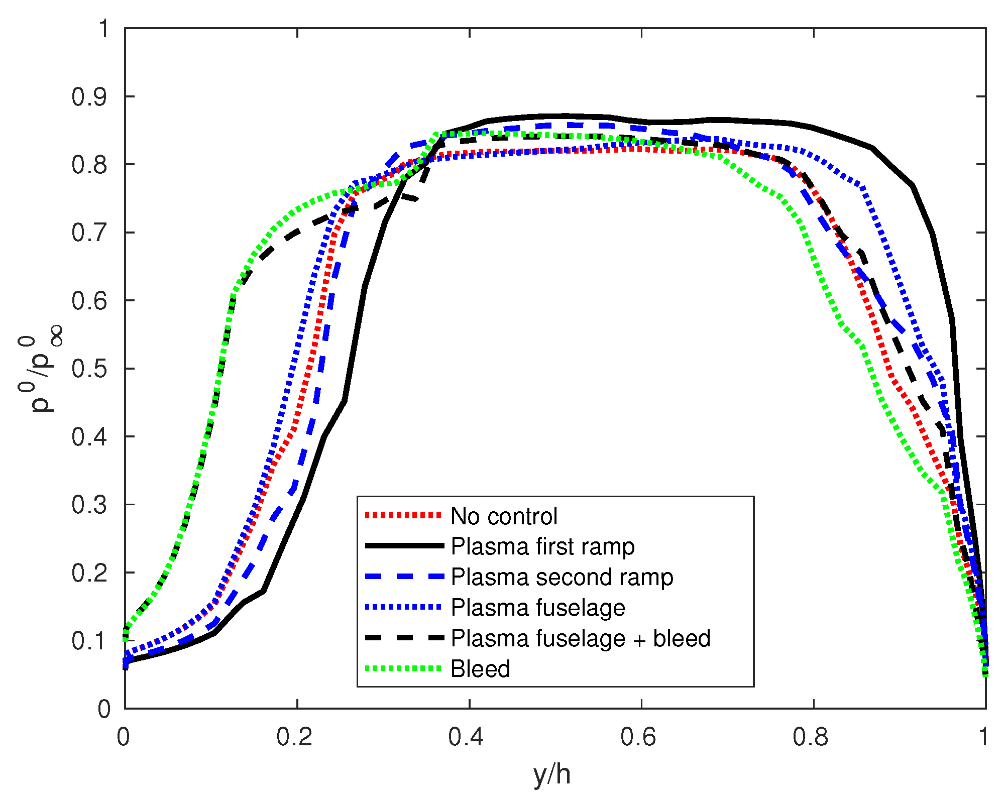
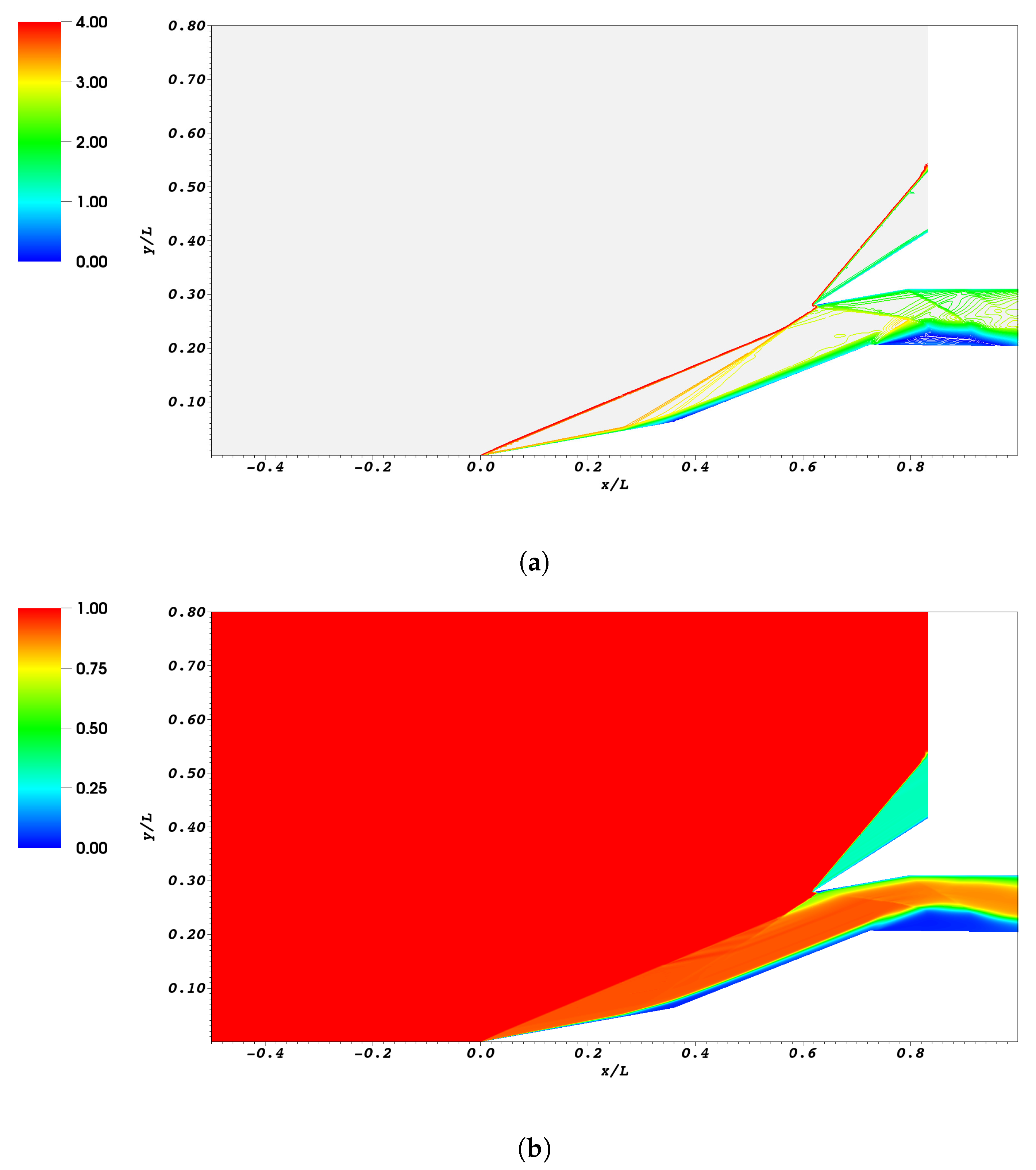
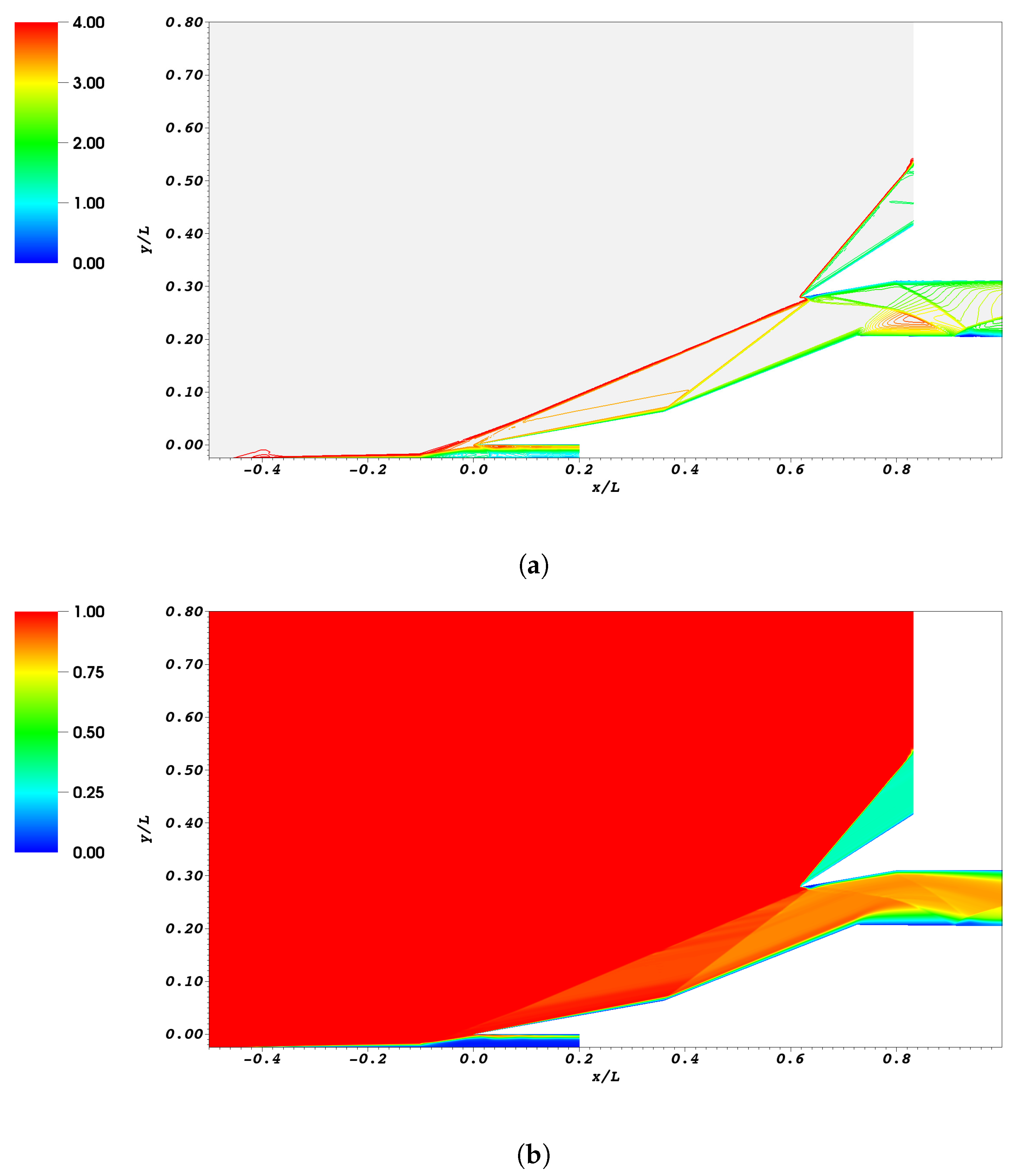
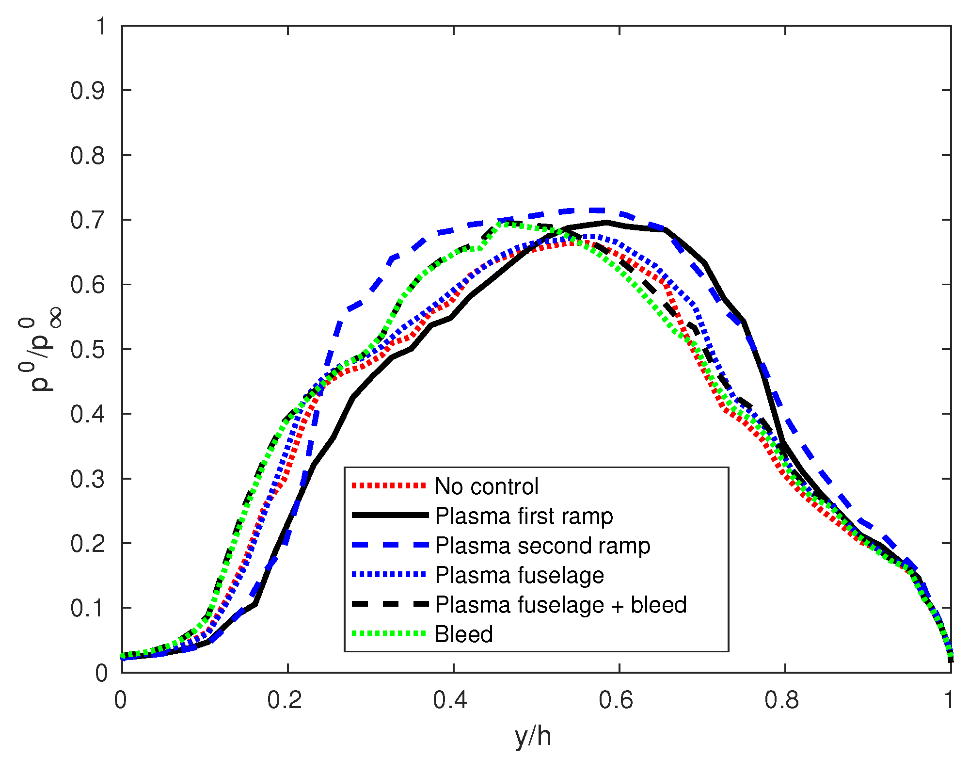
The same study was repeated for a flight Mach number . This condition is significantly far from the design condition, which can be identified by the shock-on-lip configuration, which is obtained for approximately for this geometry. The Mach number and the normalized total pressure fields for are reported in Figure 14. The plot shows that, at this flight Mach number, the shock waves generated by the two wedges have a very small slope: the shock wave obtained by their interaction enters deeply in the intake, leading to a strong separation on the lip side of the isolator. Furthermore, the reflected shocks induce an even larger separation on the bottom side of the channel. The performance indexes for this configuration are quite bad: the recovery coefficient is and the standard deviation is . Starting from such a configuration, the different control strategies are investigated in order to understand the potential and the limitations of the proposed approaches. The plot in Figure 15 shows the normalized exit total pressure distribution for the uncontrolled and controlled cases. The performance index for the different simulations are reported in Table 6.
7.2. Plasma Actuator in Front of the First Wedge at
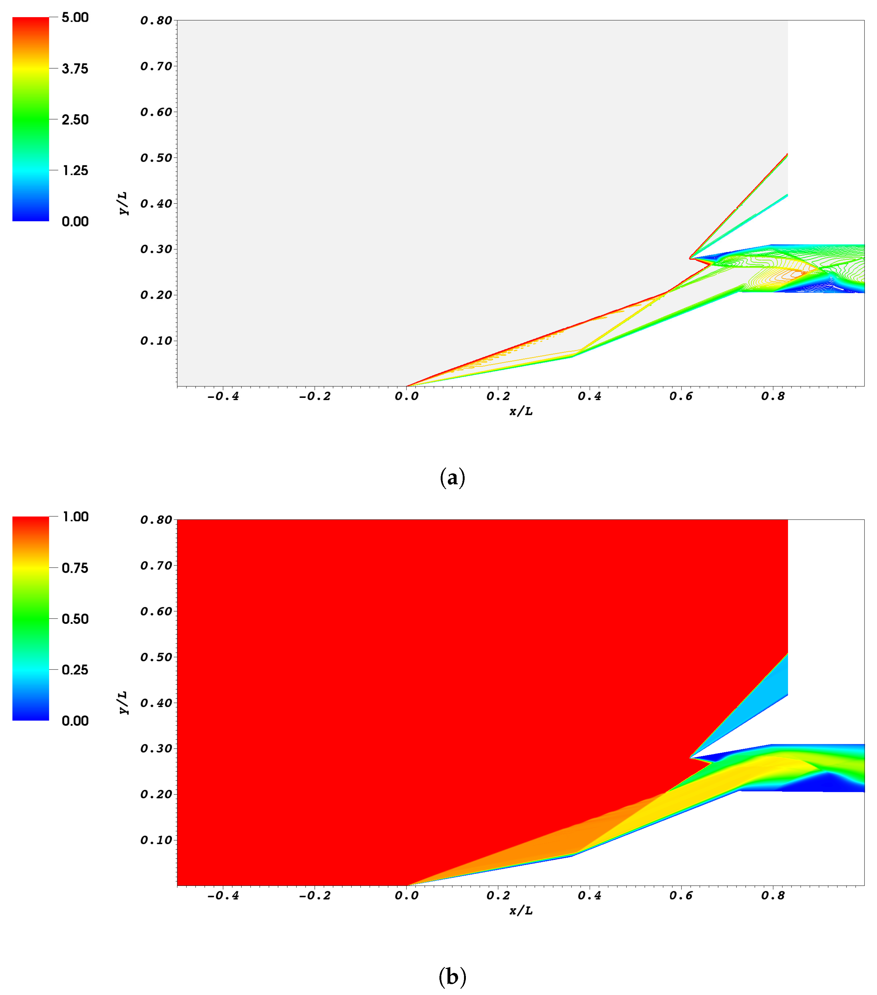
The activation of the plasma actuator in front of the first wedge leads to the development of a compression fan which collapses into a shock at a certain distance from the first corner: this can be clearly seen in both the Mach field and total pressure field reported in Figure 16. In particular, the Mach field shows the coalescence of the Mach contours while the total pressure field shows that the losses are negligible across the compression fan and become significant starting from a certain height which is determined by the coalescence of the fan’s characteristics. This results in a significant improvement of the recovery coefficient () with respect to the uncontrolled flow. The uniformity of the flow is slightly improved ().
7.3. Plasma Actuator in Front of the Second Wedge at
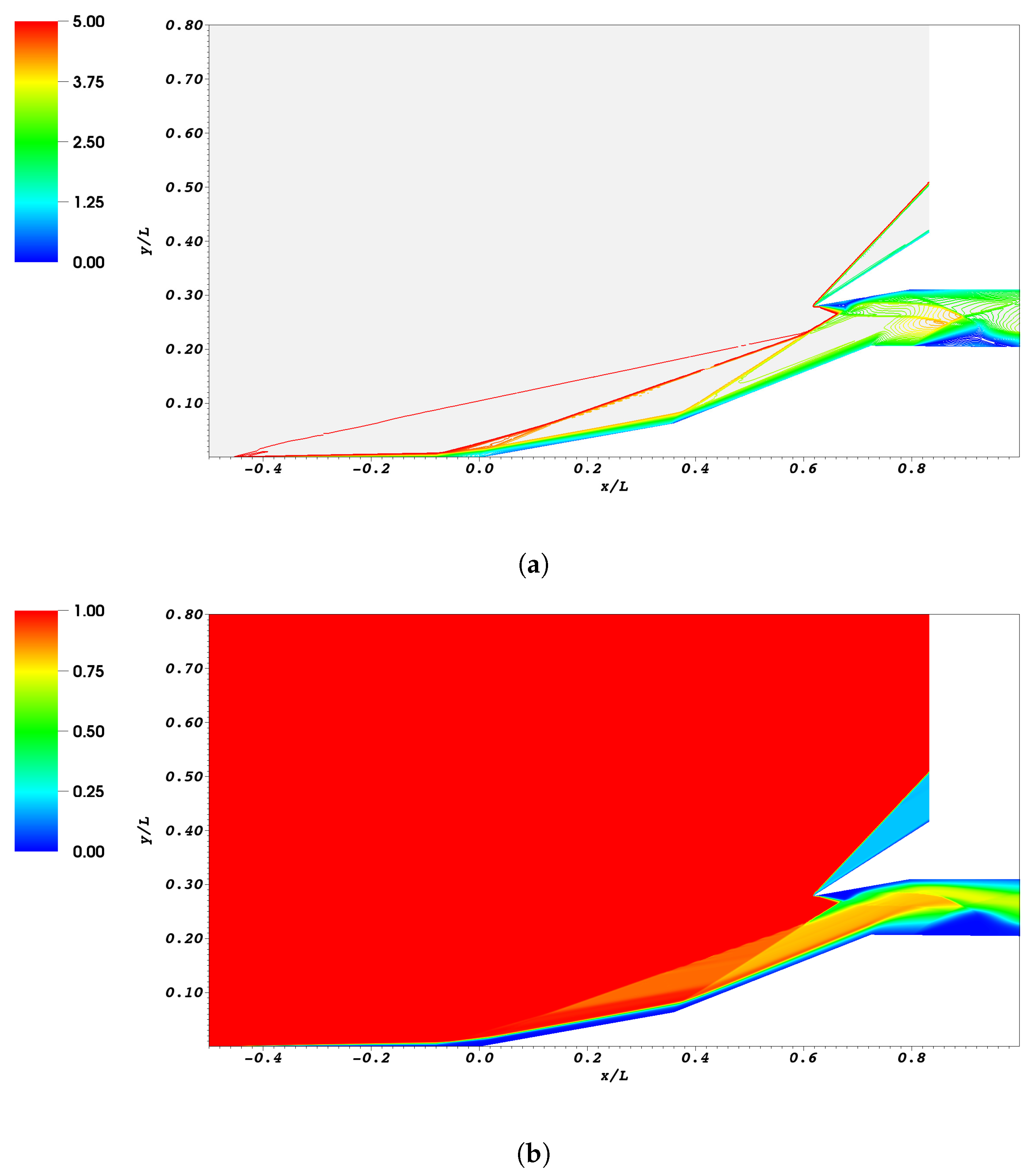
The use of the plasma actuator in front of the second wedge seems particularly effective at : the “screening” effect induced by the increased boundary layer thickness substitute the shock generated by the second wedge with a sequence of compression waves which is extended through most of the inlet streamtube. This can be clearly seen in the Figure 17a. As a consequence, the total pressure losses remains limited when the fluid passes from the first ramp region to the second ramp region, as can be seen in Figure 17b. The recovery coefficient obtained by this solution is the largest among the values predicted for the different strategies at (). Furthermore, also the homogeneity of the flow reaches the best value observed at ().
7.4. Plasma Actuator on the Fuselage at
The activation of the plasma actuator on the fuselage does not introduce significant improvements at : the perturbation induced by the actuator weakly influences the shock wave generated by the first ramp. It can be seen in Figure 18a that the shock generated by the actuator interacts with the shock generated by the first ramp in a location very close to the leading edge of the first ramp: this means that the benefits related to the presence of multiple shocks (which reduces the total pressure losses) are limited to a small portion of the stream tube. As a consequence, the recovery factor shows only a small increase () with respect to the uncontrolled case. The homogeneity of the flow () is almost equal to the uncontrolled case.
7.5. Plasma Actuator on the Fuselage and Bleed Port in the Isolator at
As is observed in the simulations, also in the simulations the plasma actuator is never able to avoid the large separation on the bottom side of the isolator. For this reason, in this case the performances of plasma actuators and bleeding were evaluated when these technologies are employed together. As already observed in Section 7.4, the plasma actuator does not alter significantly the shock wave generated by the first ramp. However, the use of bleed reduces significantly the size of the recirculation bubble in the isolator, as can be seen in Figure 19. As a consequence, the recovery coefficient () remains very similar to the value obtained without bleeding and with the actuator on the fuselage. However, the bleed improves slightly the homogeneity of the flow ().
7.6. Bleed Port in the Isolator at
Finally, a simulation without any plasma actuator and with the bleed port active was performed. As already observed in the simulation at , the bleed alone does not improve significantly the recovery coefficient because it cannot alter the shock waves generated by the two wedges. The recovery factor is obtained in this case. The beneficial effect of the bleed port on the recirculation bubble remains (see Figure 20) but it induces only a small improvement in the homogeneity of the flow ().
8. Conclusions
The use of plasma actuators was investigated for improving the performances of a supersonic inlet in off-design conditions. Starting from a very promising configuration studied by [25], several locations of the plasma actuator were investigated at different flight Mach numbers. A first set of simulations was performed at : the plasma actuator are quite effective in this off-design condition. The main effects that can be observed are the steering of the shock waves generated by the wedges and the screening effect which substitutes the shock wave with a compression fan. The configuration suggested by [25] with the actuator in front of the first ramp gives the best results in terms of recovery coefficient. However, the alternative configurations proposed in this work (actuator in front of the second ramp, actuator on the fuselage with a diverter) give better performances in terms of flow homogeneity. Furthermore, they proved to be significantly better than the uncontrolled case in terms of recovery factor. These alternative configurations can be useful in the presence of a diverter, which is used in several configurations to avoid boundary layer ingestion. Finally, a configuration in which the plasma actuator is used together with air bleed was evaluated: the bleed seems to introduce only small benefits if the performance indexes chosen for this work are considered. However, the solution with the bleed is characterized by a very small separation bubble in the isolator: since the turbulent flow in the separation region is characterized by strongly unsteady phenomena, this could represent a significant advantage which is not highlighted by the performance indexes chosen for this work.
A second set of simulations was performed at : this condition is very far from the design point and it is characterized by very large separations. Even in this case, the proposed control techniques improve sensibly the performances of the inlet. However, the best recovery factor is now obtained by the configuration with the actuator in front of the second wedge and not by the actuator in front of the first wedge. This suggests that in order to increase the operational range of the inlet, it would be useful to introduce several actuators in different positions: they should be activated one at a time depending on the particular flight Mach number.
In conclusion, the study presented in this work represents a preliminary investigation on the benefits and limitations of the proposed technology, which allowed us to quantify the magnitude of the potential performance improvements. In particular, the simulations allow us to understand how the location of the plasma actuator influences its effectiveness at different flight Mach numbers according to the physical phenomena which are induced by the actuator: shock steering and screening effect. The study is based on a simplified model of the plasma actuator, which describes it by means of an average thermal power source. This approximation is coherent with the description of the turbulent flow by means of a RANS model which provides the average flow field. The most promising configurations obtained in the present study could be investigated by more accurate, but significantly more expensive, scale-resolving 3D simulations (like e.g., LES or hybrid RANS-LES) coupled with a more sophisticated plasma model that could reduce the modeling uncertainty in the performance indexes. Furthermore, the use of 3D simulations would allow to include corner shocks from the ramps and the side walls which influence the flow field close to the end walls.
Funding
This research received no external funding.
Acknowledgments
Computational resources were provided by HPC@POLITO, a project of Academic Computing within the Department of Control and Computer Engineering at the Politecnico di Torino (http://www.hpc.polito.it).
Conflicts of Interest
The author declares no conflict of interest.
Abbreviations
The following abbreviations are used in this manuscript:
| CFD | Computational Fluid Dynamics |
| RANS | Reynolds-averaged Navier–Stokes |
| SA | Spalart–Allmaras |
| SCRAMJET | Supersonic Combustion RAMjet |
References
- Seddon, J.; Goldsmith, E.L. Intake Aerodynamics; Blackwell Science Oxford: Oxford, UK, 1999; Volume 2. [Google Scholar]
- Curran, E.; Murthy, S. Scramjet Propulsion; Progress in Astronautics and Aeronautics, American Institute of Aeronautics and Astronautics: Reston, VA, USA, 2000; Volume 189. [Google Scholar]
- Lind, C.A.; Lewis, M.J. Computational analysis of the unsteady type IV shock interaction of blunt body flows. J. Propuls. Power 1996, 12, 127–133. [Google Scholar] [CrossRef]
- Ran, H.; Mavris, D. Preliminary design of a 2D supersonic inlet to maximize total pressure recovery. In Proceedings of the AIAA 5th ATIO and16th Lighter-Than-Air Sys Tech. and Balloon Systems Conferences, Arlington, VA, USA, 26–28 September 2005; p. 7357. [Google Scholar]
- Slater, J. Design and analysis tool for external-compression supersonic inlets. In Proceedings of the 50th AIAA Aerospace Sciences Meeting including the New Horizons Forum and Aerospace Exposition, Nashville, TE, USA, 9–12 January 2012; p. 16. [Google Scholar]
- Valorani, M.; Nasuti, F.; Onofri, M.; Buongiorno, C. Optimal supersonic intake design for air collection engines (ACE). Acta Astronaut. 1999, 45, 729–745. [Google Scholar] [CrossRef]
- Kim, S.D.; Song, D.J. Numerical study on performance of supersonic inlets with various three-dimensional bumps. J. Mech. Sci. Technol. 2008, 22, 1640–1647. [Google Scholar] [CrossRef]
- Farahani, M.; Mahdavi, M. A proposed design method for supersonic inlet to improve performance parameters. Aerosp. Sci. Technol. 2019, 91, 583–592. [Google Scholar] [CrossRef]
- Gounko, Y.P.; Mazhul, I. Gasdynamic design of a two-dimensional supersonic inlet with the increased flow rate factor. Thermophys. Aeromech. 2012, 19, 363–379. [Google Scholar] [CrossRef]
- Surber, L.; Tinapple, J. Inlet flow control technology: Learning from history, reinventing the future. In Proceedings of the 50th AIAA Aerospace Sciences Meeting Including the New Horizons Forum and Aerospace Exposition, Nashville, TE, USA, 9–12 January 2012; p. 12. [Google Scholar]
- Guna, H.; Kaushik, M.; Sinhamahapatra, K.P. Shock Boundary Layer Interaction Control in Supersonic Intake using Cavity with Porous Surface. In Proceedings of the 35th AIAA Applied Aerodynamics Conference, Denver, CO, USA, 5–9 June 2017. [Google Scholar]
- Grasso, F.; Marini, M. Analysis of hypersonic shock-wave laminar boundary-layer interaction phenomena. Comput. Fluids 1996, 25, 561–581. [Google Scholar] [CrossRef]
- Doerffer, P.; Szulc, O. Shock wave strength reduction by passive control using perforated plates. J. Therm. Sci. 2007, 16, 97–104. [Google Scholar] [CrossRef]
- Gunasekaran, H.; Thangaraj, T.; Jana, T.; Kaushik, M. Effects of Wall Ventilation on the Shock-wave/Viscous-Layer Interactions in a Mach 2.2 Intake. Processes 2020, 8, 208. [Google Scholar] [CrossRef] [Green Version]
- Mrozinski, D.; Hayes, J. Numerical and experimental analysis of a hypersonic variable geometry inlet. In Proceedings of the 37th Aerospace Sciences Meeting and Exhibit, Reno, NV, USA, 11–14 January 1999; p. 899. [Google Scholar]
- Pitt, D.; Dunne, J.; White, E.; Garcia, E. SAMPSON smart inlet SMA powered adaptive lip design and static test. In Proceedings of the 19th AIAA Applied Aerodynamics Conference, Anaheim, CA, USA, 11–14 June 2001; p. 1359. [Google Scholar]
- Zhang, Y.; Tan, H.J.; Li, J.F.; Chen, H.; Wang, C. Ramp Shock Regulation of Supersonic Inlet with Shape Memory Alloy Plate. AIAA J. 2018, 56, 1696–1702. [Google Scholar] [CrossRef]
- Domel, N.; Baruzzini, D. A perspective on mixed-compression inlets and the use of CFD and flow control in the design process. In Proceedings of the 50th AIAA Aerospace Sciences Meeting Including the New Horizons Forum and Aerospace Exposition, Nashville, TE, USA, 9–12 January 2012; p. 14. [Google Scholar]
- Macheret, S.O.; Shneider, M.N.; Miles, R.B. Scramjet inlet control by off-body energy addition: A virtual cowl. AIAA J. 2004, 42, 2294–2302. [Google Scholar] [CrossRef]
- John, B.; Vijapuri, D.; Thota, B.; Katoch, N. Energy Addition–Based Virtual Cowl for Performance Enhancement of Scramjet Intake. J. Aerosp. Eng. 2019, 32, 04019076. [Google Scholar] [CrossRef]
- Shneider, M.; Macheret, S.; Miles, R. Comparative analysis of MHD and plasma methods of scramjet inlet control. In Proceedings of the 41st Aerospace Sciences Meeting and Exhibit, Reno, NV, USA, 6–9 January 2003; p. 170. [Google Scholar]
- Bisek, N.; Rizzetta, D.; Poggie, J. Exploration of plasma control for supersonic turbulent flow over a compression ramp. In Proceedings of the 42nd AIAA Fluid Dynamics Conference and Exhibit, New Orleans, LA, USA, 25–28 June 2006; p. 2700. [Google Scholar]
- Caraballo, E.; Webb, N.; Little, J.; Kim, J.H.; Samimy, M. Supersonic inlet flow control using plasma actuators. In Proceedings of the 47th AIAA Aerospace Sciences Meeting including The New Horizons Forum and Aerospace Exposition, Orlando, FL, USA, 5–8 January 2009; p. 924. [Google Scholar]
- Leonov, S.B.; Yarantsev, D.A. Near-surface electrical discharge in supersonic airflow: Properties and flow control. J. Propuls. Power 2008, 24, 1168–1181. [Google Scholar] [CrossRef]
- Falempin, F.; Firsov, A.A.; Yarantsev, D.A.; Goldfeld, M.A.; Timofeev, K.; Leonov, S.B. Plasma control of shock wave configuration in off-design mode of M= 2 inlet. Exp. Fluids 2015, 56, 54. [Google Scholar] [CrossRef]
- Konstantinidis, E. Active Control of Bluff-Body Flows Using Plasma Actuators. Actuators 2019, 8, 66. [Google Scholar] [CrossRef] [Green Version]
- Hasan, M.; Atkinson, M. Investigation of a Dielectric Barrier Discharge Plasma Actuator to Control Turbulent Boundary Layer Separation. Appl. Sci. 2020, 10, 1911. [Google Scholar] [CrossRef] [Green Version]
- Ferrero, A.; Pastrone, D. Plasma Actuator–Assisted Rocket Nozzle for Improved Launcher Performance. AIAA J. 2019, 57, 1348–1354. [Google Scholar] [CrossRef]
- Allmaras, S.R.; Johnson, F.T. Modifications and clarifications for the implementation of the Spalart–Allmaras turbulence model. In Proceedings of the Seventh International Conference on Computational Fluid Dynamics (ICCFD7), Big Island, HI, USA, 9–13 July 2012; pp. 1–11. [Google Scholar]
- Menter, F.R. Two-equation eddy-viscosity turbulence models for engineering applications. AIAA J. 1994, 32, 1598–1605. [Google Scholar] [CrossRef] [Green Version]
- Launder, B.E.; Spalding, D.B. The numerical computation of turbulent flows. In Numerical Prediction of Flow, Heat Transfer, Turbulence and Combustion; Elsevier: Amsterdam, The Netherlands, 1983; pp. 96–116. [Google Scholar]
- Capello, E.; Ferrero, A.; Marsilio, R.; Ferlauto, M. CFD-based Fluidic Thrust Vectoring model for fighter aircraft. In Proceedings of the AIAA Propulsion and Energy 2019 Forum, Indianapolis, IN, USA, 19–22 August 2019; p. 4311. [Google Scholar]
- Ferrero, A.; Iollo, A.; Larocca, F. Field inversion for data-augmented RANS modelling in turbomachinery flows. Comput. Fluids 2020, 201, 104474. [Google Scholar] [CrossRef]
- Spalart, P.R.; Rumsey, C.L. Effective inflow conditions for turbulence models in aerodynamic calculations. AIAA J. 2007, 45, 2544–2553. [Google Scholar] [CrossRef]
- Luo, W.; Wei, Y.; Dai, K.; Zhu, J.; You, Y. Spatiotemporal Characterization and Suppression Mechanism of Supersonic Inlet Buzz with Proper Orthogonal Decomposition Method. Energies 2020, 13, 217. [Google Scholar] [CrossRef] [Green Version]
- Trapier, S.; Duveau, P.; Deck, S. Experimental study of supersonic inlet buzz. AIAA J. 2006, 44, 2354–2365. [Google Scholar] [CrossRef]
- Koo, H.; Raman, V. Large-eddy simulation of a supersonic inlet-isolator. AIAA J. 2012, 50, 1596–1613. [Google Scholar] [CrossRef]
- Sun, P.Z.; Shi, H.T.; Lu, X.Y. Numerical investigation of the unsteady behavior of a hypersonic inlet under throttling. Procedia Eng. 2015, 126, 179–183. [Google Scholar] [CrossRef] [Green Version]
- Trapier, S.; Deck, S.; Duveau, P. Delayed detached-eddy simulation and analysis of supersonic inlet buzz. AIAA J. 2008, 46, 118–131. [Google Scholar] [CrossRef]
- Grenson, P.; Beneddine, S. Analysis of shock oscillations of an external compression supersonic inlet through unsteady numerical simulations. In Proceedings of the 2018 Applied Aerodynamics Conference, Atlanta, GA, USA, 25–29 June 2018; p. 3011. [Google Scholar]
- Shang, J.J. Computational Electromagnetic-Aerodynamics; John Wiley & Sons: Hoboken, NJ, USA, 2016. [Google Scholar]
- Ferrero, A.; Larocca, F. Feedback filtering in discontinuous Galerkin methods for Euler equations. Prog. Comput. Fluid Dyn. Int. J. 2016, 16, 14–25. [Google Scholar] [CrossRef]
- Ferrero, A.; Larocca, F. Adaptive CFD Schemes for Aerospace Propulsion; Journal of Physics: Conference Series; IOP Publishing: Bristol, UK, 2017; Volume 841, p. 012017. [Google Scholar]
- Ferrero, A.; Larocca, F.; Puppo, G. A robust and adaptive recovery-based discontinuous Galerkin method for the numerical solution of convection–diffusion equations. Int. J. Numer. Methods Fluids 2015, 77, 63–91. [Google Scholar] [CrossRef]
- Ampellio, E.; Bertini, F.; Ferrero, A.; Larocca, F.; Vassio, L. Turbomachinery design by a swarm-based optimization method coupled with a CFD solver. Adv. Aircr. Spacecr. Sci. 2016, 3, 149. [Google Scholar] [CrossRef]
- Ferrero, A.; Larocca, F.; Bernaschek, V. Unstructured discretisation of a non-local transition model for turbomachinery flows. Adv. Aircr. Spacecr. Sci. 2017, 4, 555–571. [Google Scholar]
- Ferrero, A.; Iollo, A.; Larocca, F. Global and local POD models for the prediction of compressible flows with DG methods. Int. J. Numer. Methods Eng. 2018, 116, 332–357. [Google Scholar] [CrossRef] [Green Version]
- Ferrero, A.; Iollo, A.; Larocca, F. RANS closure approximation by artificial neural networks. In Proceedings of the ETC 2019-13th European Turbomachinery Conference on Turbomachinery Fluid Dynamics and Thermodynamics, Lausanne, Switzerland, 8–12 April 2019. [Google Scholar]
- Conte, A.; Ferrero, A.; Larocca, F.; Pastrone, D. Numerical Tool Optimization for Advanced Rocket Nozzle Performance Prediction. In Proceedings of the AIAA Propulsion and Energy 2019 Forum, Indianapolis, IN, USA, 19–22 August 2019; p. 4115. [Google Scholar]
- Ferrero, A.; Iollo, A.; Larocca, F. Reduced order modelling for turbomachinery shape design. Int. J. Comput. Fluid Dyn. 2019. [Google Scholar] [CrossRef]
- Liou, M.S. A sequel to ausm: Ausm+. J. Comput. Phys. 1996, 129, 364–382. [Google Scholar] [CrossRef]
- Barth, T.; Jespersen, D. The design and application of upwind schemes on unstructured meshes. In Proceedings of the 27th Aerospace Sciences Meeting, Reno, NV, USA, 9–12 January 1989; p. 366. [Google Scholar]
- Lange, M.; Knepley, M.G.; Gorman, G.J. Flexible, scalable mesh and data management using PETSc DMPlex. In Proceedings of the 3rd International Conference on Exascale Applications and Software, University of Edinburgh, Edinburgh, UK, 21–23 April 2015; pp. 71–76. [Google Scholar]
- Balay, S.; Abhyankar, S.; Adams, M.; Brown, J.; Brune, P.; Buschelman, K.; Dalcin, L.; Dener, A.; Eijkhout, V.; Gropp, W.; et al. PETSc Users Manual. Available online: https://www.mcs.anl.gov/petsc/ (accessed on 18 March 2020).
- Geuzaine, C.; Remacle, J.F. Gmsh: A 3-D finite element mesh generator with built-in pre-and post-processing facilities. Int. J. Numer. Methods Eng. 2009, 79, 1309–1331. [Google Scholar] [CrossRef]
- Remacle, J.F.; Henrotte, F.; Carrier-Baudouin, T.; Béchet, E.; Marchandise, E.; Geuzaine, C.; Mouton, T. A frontal Delaunay quad mesh generator using the L-infinite norm. Int. J. Numer. Methods Eng. 2013, 94, 494–512. [Google Scholar] [CrossRef]
- Curran, E.; Heiser, W.; Pratt, D. Fluid phenomena in scramjet combustion systems. Annu. Rev. Fluid Mech. 1996, 28, 323–360. [Google Scholar] [CrossRef]
- Schneider, A.; Koschel, W. Detailed analysis of a mixed compression hypersonic intake. In Proceedings of the Fourteenth International Symposium on Air Breathing Engines, Florence, Italy, 5–10 September 1999. ISABE paper 99-7036. [Google Scholar]
- John, B.; Senthilkumar, P. Alterations of cowl lip for the improvement of supersonic-intake performance. J. Appl. Fluid Mech. 2018, 11, 31–41. [Google Scholar] [CrossRef]
- Air Intakes for High Speed Vehicles; AGARD-AR-270; AGARD: Grantham, UK, 1991.
Figure 1.
Computational domain for configuration A (a) and configuration B (b).

Figure 2.
Source term in configuration A with actuator in front of the first ramp (a), configuration A with actuator in front of the second ramp (b) and configuration B (c).
Figure 2.
Source term in configuration A with actuator in front of the first ramp (a), configuration A with actuator in front of the second ramp (b) and configuration B (c).

Figure 3.
Example of computational mesh for configuration A (a) and configuration B (b).

Figure 4.
Mach number field (a) and normalized total pressure field (b) at without control.

Figure 5.
Comparison of the wall pressure distribution at with experimental and numerical results from literature.
Figure 5.
Comparison of the wall pressure distribution at with experimental and numerical results from literature.

Figure 6.
Dimensionless wall distance distribution for different grids.

Figure 7.
Mach number (a) and normalized total pressure field (b) at without control.

Figure 8.
Controlled flow at with actuator in front of the first ramp: Mach field (a) and normalized total pressure field (b).
Figure 8.
Controlled flow at with actuator in front of the first ramp: Mach field (a) and normalized total pressure field (b).

Figure 9.
Exit total pressure distribution at for uncontrolled and controlled cases.

Figure 10.
Controlled flow at with actuator in front of the second ramp: Mach field (a) and normalized total pressure field (b).
Figure 10.
Controlled flow at with actuator in front of the second ramp: Mach field (a) and normalized total pressure field (b).

Figure 11.
Controlled flow at with actuator on the fuselage: Mach field (a) and normalized total pressure field (b).
Figure 11.
Controlled flow at with actuator on the fuselage: Mach field (a) and normalized total pressure field (b).

Figure 12.
Controlled flow at with actuator on the fuselage and bleed at : Mach field (a) and normalized total pressure field (b).
Figure 12.
Controlled flow at with actuator on the fuselage and bleed at : Mach field (a) and normalized total pressure field (b).

Figure 13.
Controlled flow at with bleed at : Mach field (a) and normalized total pressure field (b).
Figure 13.
Controlled flow at with bleed at : Mach field (a) and normalized total pressure field (b).

Figure 14.
Uncontrolled flow at : Mach field (a) and normalized total pressure field (b).

Figure 15.
Exit total pressure distribution at for uncontrolled and controlled cases.

Figure 16.
Controlled flow at with actuator in front of the first ramp: Mach field (a) and normalized total pressure field (b).
Figure 16.
Controlled flow at with actuator in front of the first ramp: Mach field (a) and normalized total pressure field (b).

Figure 17.
Controlled flow at with actuator in front of the second ramp: Mach field (a) and normalized total pressure field (b).
Figure 17.
Controlled flow at with actuator in front of the second ramp: Mach field (a) and normalized total pressure field (b).

Figure 18.
Controlled flow at with actuator on the fuselage: Mach field (a) and normalized total pressure field (b).
Figure 18.
Controlled flow at with actuator on the fuselage: Mach field (a) and normalized total pressure field (b).

Figure 19.
Controlled flow at with actuator on the fuselage and bleed at : Mach number field (a) and normalized total pressure field (b).
Figure 19.
Controlled flow at with actuator on the fuselage and bleed at : Mach number field (a) and normalized total pressure field (b).

Figure 20.
Controlled flow at with bleed at : Mach field (a) and normalized total pressure field (b).
Figure 20.
Controlled flow at with bleed at : Mach field (a) and normalized total pressure field (b).


Table 1.
Coordinates of points for configuration A.
| Point | A | B | C | D | E | F | G | H | I | L | M | N |
|---|---|---|---|---|---|---|---|---|---|---|---|---|
| x/L | −0.500 | −0.450 | 0.00 | 0.353 | 0.720 | 1.00 | 1.00 | 0.797 | 0.617 | 0.832 | 0.832 | −0.500 |
| y/L | 0.00 | 0.00 | 0.00 | 0.0623 | 0.207 | 0.204 | 0.310 | 0.310 | 0.280 | 0.426 | 0.800 | 0.800 |
Table 2.
Coordinates of points for configuration B (if not reported here, same value of Table 1).
Table 2.
Coordinates of points for configuration B (if not reported here, same value of Table 1).
| Point | A | B | O | P | Q | R |
|---|---|---|---|---|---|---|
| x/L | −0.500 | −0.450 | 0.200 | 0.200 | 0.900 | 0.910 |
| y/L | −0.025 | −0.0250 | −0.0250 | 0.00 | 0.205 | 0.205 |
Table 3.
Boundary conditions for configuration A.
| Segment | Boundary Condition |
|---|---|
| A-B, M-N | Symmetry |
| A-N | Inlet |
| F-G, L-M | Outlet |
| C-D, D-E, E-F, G-H, H-I, I-L | Solid wall |
| B-C | Solid wall or symmetry (depending on the test case) |
Table 4.
Boundary conditions for configuration B.
| Segment | Boundary Condition |
|---|---|
| A-B, M-N | Symmetry |
| A-N | Inlet |
| F-G, L-M, P-O | Outlet |
| C-D, D-E, E-Q, R-F, G-H, H-I, I-L, C-P, B-O | Solid wall |
| Q-R | Solid wall or exit (depending on bleed activation) |
Table 5.
Performances of the inlet at .
| Control Strategy | Recovery Coefficient R | Standard Deviation |
|---|---|---|
| No control | 0.665 | 0.223 |
| Plasma actuator first ramp | 0.740 | 0.244 |
| Plasma actuator second ramp | 0.690 | 0.225 |
| Plasma actuator fuselage | 0.693 | 0.203 |
| Plasma actuator fuselage + bleed | 0.688 | 0.170 |
| Bleed | 0.679 | 0.191 |
Table 6.
Performances of the inlet at .
| Control Strategy | Recovery Coefficient R | Standard Deviation |
|---|---|---|
| No control | 0.456 | 0.288 |
| Plasma actuator first ramp | 0.483 | 0.279 |
| Plasma actuator second ramp | 0.500 | 0.276 |
| Plasma actuator fuselage | 0.470 | 0.289 |
| Plasma actuator fuselage + bleed | 0.468 | 0.280 |
| Bleed | 0.460 | 0.285 |
© 2020 by the author. Licensee MDPI, Basel, Switzerland. This article is an open access article distributed under the terms and conditions of the Creative Commons Attribution (CC BY) license (http://creativecommons.org/licenses/by/4.0/).
Share and Cite
MDPI and ACS Style
Ferrero, A. Control of a Supersonic Inlet in Off-Design Conditions with Plasma Actuators and Bleed. Aerospace 2020, 7, 32. https://doi.org/10.3390/aerospace7030032
AMA Style
Ferrero A. Control of a Supersonic Inlet in Off-Design Conditions with Plasma Actuators and Bleed. Aerospace. 2020; 7(3):32. https://doi.org/10.3390/aerospace7030032
Chicago/Turabian StyleFerrero, Andrea. 2020. "Control of a Supersonic Inlet in Off-Design Conditions with Plasma Actuators and Bleed" Aerospace 7, no. 3: 32. https://doi.org/10.3390/aerospace7030032
Note that from the first issue of 2016, this journal uses article numbers instead of page numbers. See further details here.