1. Introduction
Nano satellites represent an emerging opportunity to pursue a broad set of mission goals, including science and space exploration [
1,
2], technology demonstration [
3,
4], debris removal [
5], Earth Observation [
6], and communications [
7] at low cost and fast delivery. With the strong market demand for affordable space assets, there is little doubt that the number of small satellites will continue to grow [
8]. Small satellites are projected into a brilliant future, but the technology still needs improvements, and the process of manufacturing, assembly, integration, and verification will become more efficient. In this framework, miniaturized propulsion systems greatly increase the range of mission concept achievable with multi-unit CubeSats (6U+) in terms of orbit change and raising, station keeping, and orbit maintenance against the disturbances, formation flying, proximity operations, and de-orbit [
9,
10,
11,
12], but many systems still remain at a low technology readiness level because they are never integrated with a CubeSat platform. That is mainly due to a gap between the actual CubeSat capabilities and the lack of knowledge about the real interaction between the propulsion system and the CubeSat technology.
At the subsystem level (i.e., propulsion system level), many concepts have been recently developed and relevant test campaigns in a representative environment have been conducted. A complete overview of the actual miniaturized propulsion systems is generated from the lists and description made in [
13,
14]. In [
15], the authors provide a valuable description of the actual state of art of space propulsion technology for small satellites, going through the chemical, electrical, and propellant-less propulsion system, providing comparisons and highlighting some of the issues at system and mission levels adopting propulsion systems.
Moreover, many test campaigns of stand-alone propulsion systems have been conducted both for incremental and disruptive technologies. T4I srl (a spin-off enterprise of the University of Padua [
16]) and University of Padua developed a helicon plasma thruster that performed stand/alone functional and environmental tests (i.e., vibrations and vacuum sessions) [
17]. University of Stuttgart proposes a Pulse Plasma Thruster, called Petrus, verified through hardware in the loop simulations that allows for the evaluation of the propulsion system’s performance [
18]. The design, integration, and the road to qualification of the Adelis-SAMSON nano-satellite cold-gas propulsion system is proposed in [
19], but the focus is on component levels in the propellant tank, thruster assembly, pressure regulators, and fill and vent valves. The development of a thrust stand to enable the direct measurement of thrust and specific impulse for a CubeSat propulsion system during firing is shown in [
20]: the processes, setups, and calibration phases of the ground support equipment made of an inverted pendulum that incorporates the thrust balance are detailed. An iodine-fueled RF ion propulsion system (compatible with the 6U CubeSat form-factor) is developed by Busek that performed the integration and functional test at component level ((i.e., the flight PPU subsystem, including a demonstration of thruster-cathode hot fire with the full suite of PPU breadboards) and the random vibration test of other mechanical parts (e.g., the gimbal elements) [
21]. The author in [
22] shows the setup and the results of the performance tests (made at Georgia Tech facilities) of a cold gas (with the majority parts manufactured with 3D-printing technology) for an attitude control thruster produced for the BioSentinel spacecraft. ExoTerra concluded several rounds of testing of its Micro Electric Propulsion system for CubeSats, including performance testing of the thruster operating envelope, initial life testing, and integrated sub-system testing up to the stand-alone qualification [
23].
Beyond the research for the higher performance of the propulsion system, its challenging integrability with actual small satellites technology and the difficulty to complete an effective test campaign generate the gap for the propulsion solutions, slowing down the introduction of the miniaturized propulsion system in the space domain, missions, and market. Propulsion systems risk being inapplicable at the system level because they require resources that the spacecraft cannot provide. Similarly, the state-of-the-art solutions of small satellite avionics and mechanical subsystems are not really compliant with the propulsion system requirements in terms of mean and peak power consumption, operating voltage, mechanical interfaces, and the protection of sensible parts (e.g., electro-optics devices) from contamination, electro-magnetic field emissions, and thermal fluxes.
The assessment of the mutual impact between the miniaturized electric propulsion system and the CubeSat technology becomes a stepping stone to speed up the propulsion system availability because it allows a confirmation of the operativity and the performance obtained at subsystem level and/or anticipate potential misbehaviors and gives advice to the propulsion systems and platforms developers as well as launch providers on the required improvements. This second aspect is one of the focal points of the research, in that it does not simply aim at verifying performance requirements (e.g., the thrust) but also focuses on investigating as deeply as possible the issues deriving from the mutual impact between the onboard systems.
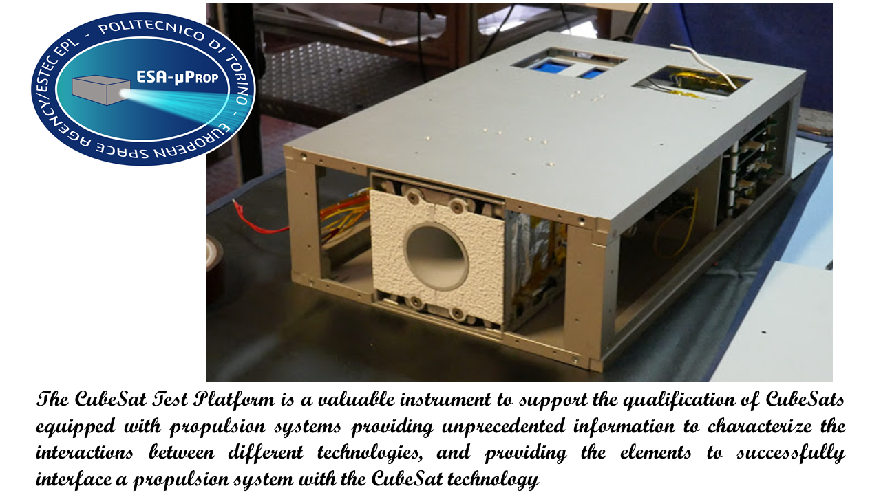
Since 2017, Politecnico di Torino has led an experimental research program, sponsored by ESA, that aims to assess the effects on the small-sat operations and the interactions between miniaturized propulsion systems and a CubeSat platform. The main output of the first part of the research is a 6U platform based on CubeSat technology and developed to host miniaturized propulsion systems in order to obtain unprecedented measurements inside the platform and to support the propulsion systems operations through new elements. While parts of the measurements required for this assessment can be gathered using well-known ground support equipment, in some cases prepared and tailored for the reduced dimensions of the objects under test, other important measurements can be taken through RF sensing circuits, Line Impedance Stability Network (LISN) circuits, combined temperature sensors, and miniaturized acquisition circuits and mechanical supports, installed inside the platform. Moreover, specific elements of the platform are dedicated to the propulsion system operations, such as a high-power supplier system compatible with the small-sat/CubeSat dimensions and made of reliable commercial shelf components.
The present paper deals with the description of the updated CubeSat test platform, providing details of the adopted solutions and the results obtained during the test campaigns conducted in laboratory conditions and in a relevant environment that validates the platform design.
2. CubeSat Test Platform Description
The CubeSat Test Platform (CTP) is an updated version of the previous version described in [
24]. The design is focused on the capability to interface the majority of the European (uPS) in terms of power supplying, command and data exchange and sharing, mechanical and fluidics connections, and to gather information on the thermal environment, the radio-frequency emissions and the electromagnetic interference, the electrical power consumptions, and the chemical contamination of the platform surfaces and external elements (such as solar panels).
The CubeSat Test Platform features an Al-alloy 6U structure, in which a Propulsion Box hosts the propulsion system (up to 4U), and a Service Module contains the on-board avionics (1U), and battery packs (1U).
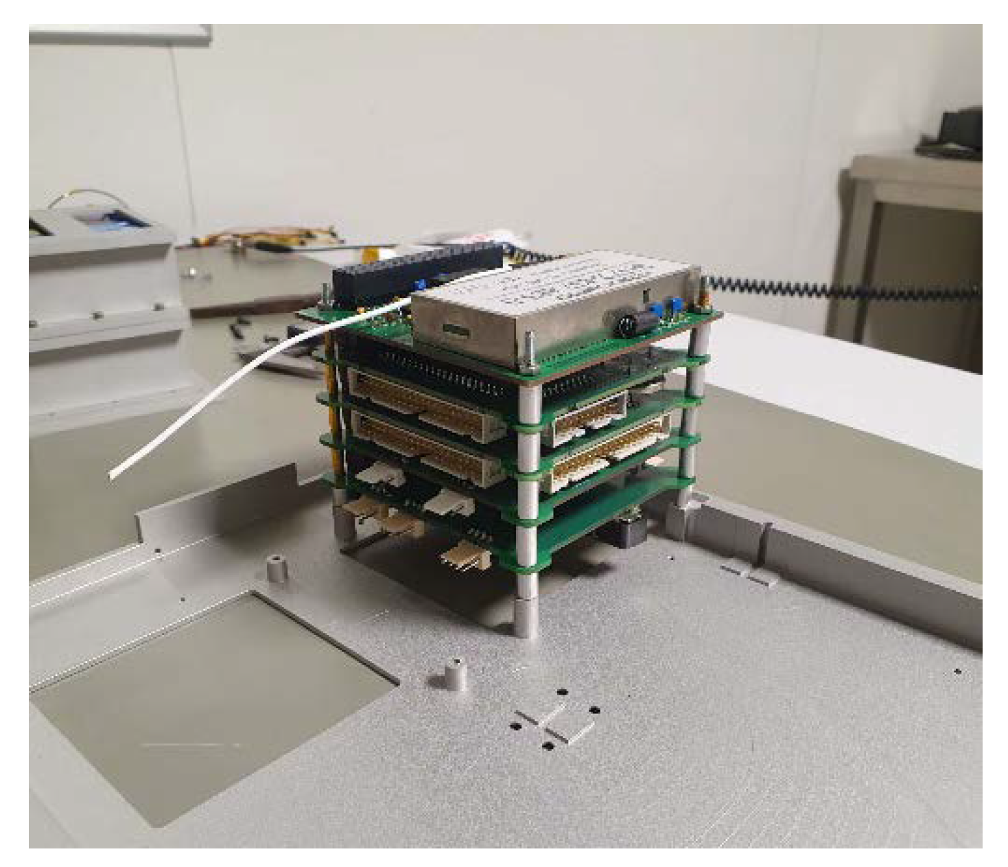
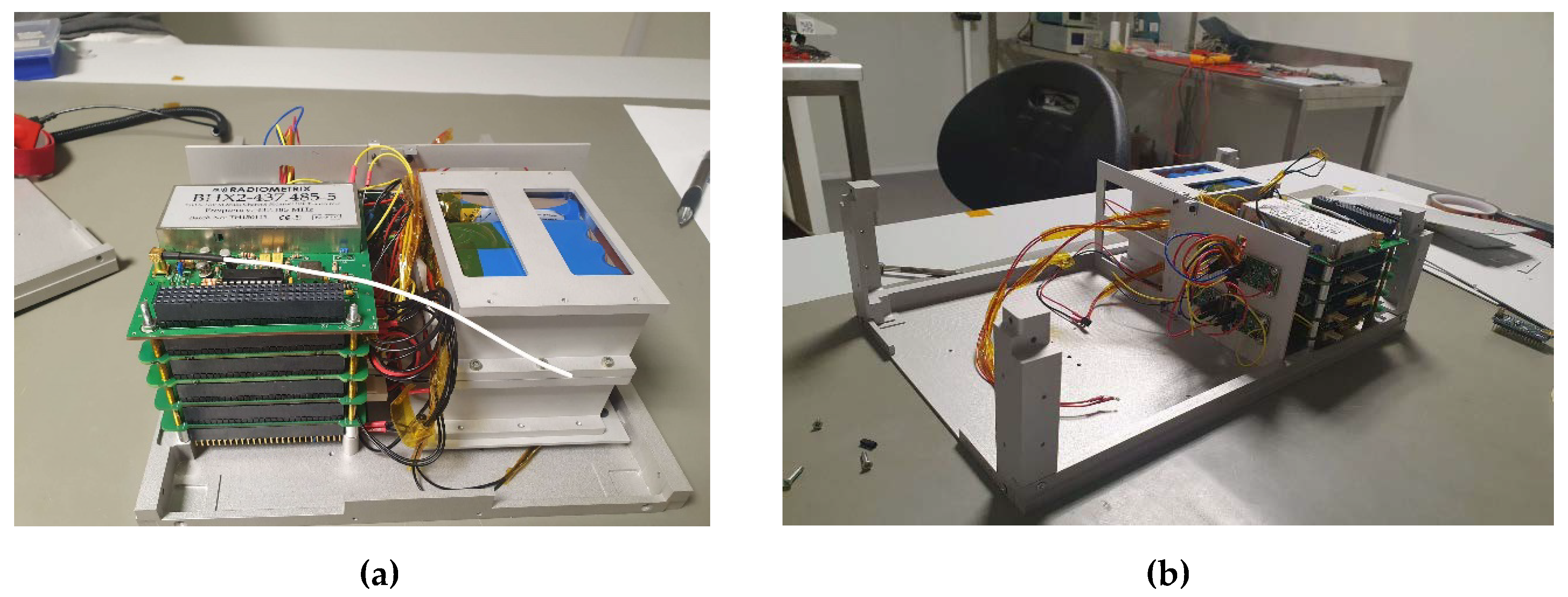
The avionics systems are in-house developed electronic boards representative of the CubeSats technology. The avionics box (
Figure 1) is constituted by the Propulsion Interface System (PIS) that manages the data and power exchanges with the propulsion system and a basic CubeSat module made of the Command and Data Handling board, the Electrical Power System (PCDU and battery, without solar panels), and the communication module (UHF for housekeeping and experiment data transmission). The boards are connected through a 104-pins bus connector in order to electrical power supplying and data exchange and mounted on a stack of four bars that fix the avionics box to the primary structure.
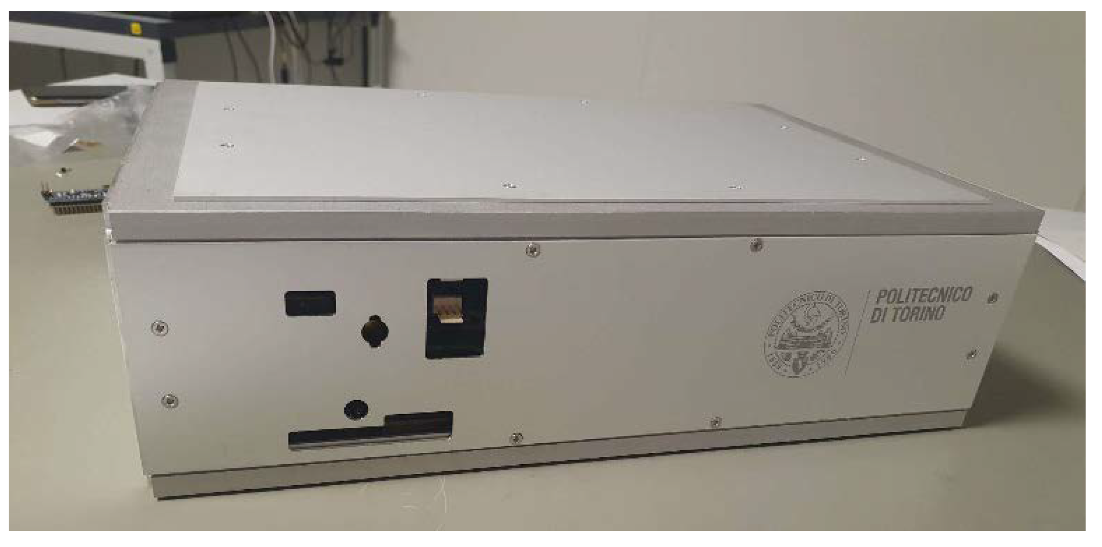
The external interfaces (battery packs recharging ports, hardline connectors, and switches) are available on the +Y face. The electrical and data interfaces towards the propulsion system are located on the other side of the box (
Figure 2).
2.1. Propulsion Interface System
The Propulsion Interface System (PIS) provides the interfaces of CTP towards the propulsion system and the instruments and devices to measure the parameters for assessing the interactions between the CTP and the propulsion system. Two main parts constitute PIS: the Data Logging System (DLS) and the High-Power Management System (HPMS).
Data Logging (DLS) acquires many measurements through an electronics board. This board is part of the Avionics stack and mainly hosts the conditioning RC filters and amplifiers and two 16-channel Analog-to-Digital Converter (ADC). The outputs of the ADC are passed to the CDH board via an SPI bus.
Sixteen temperature sensors (twelve NTCs and four PT1000s) provide temperatures of the Propulsion Box in the range [−20; 120] degC and [−40; +350] degC, respectively. The PT100 sensors are located near to the thruster and on the propulsion system case while the NTC are fixed on the bulkhead (4), on the faces (+Y, −Y, +Z, −Z), four inside Propulsion box close to the propulsion system and four on the external surfaces. The other twelve NTCs are installed in the avionics box and the battery packs. All these sensors help to characterize the thermal environment, mainly inside the CTP and in its proximity.
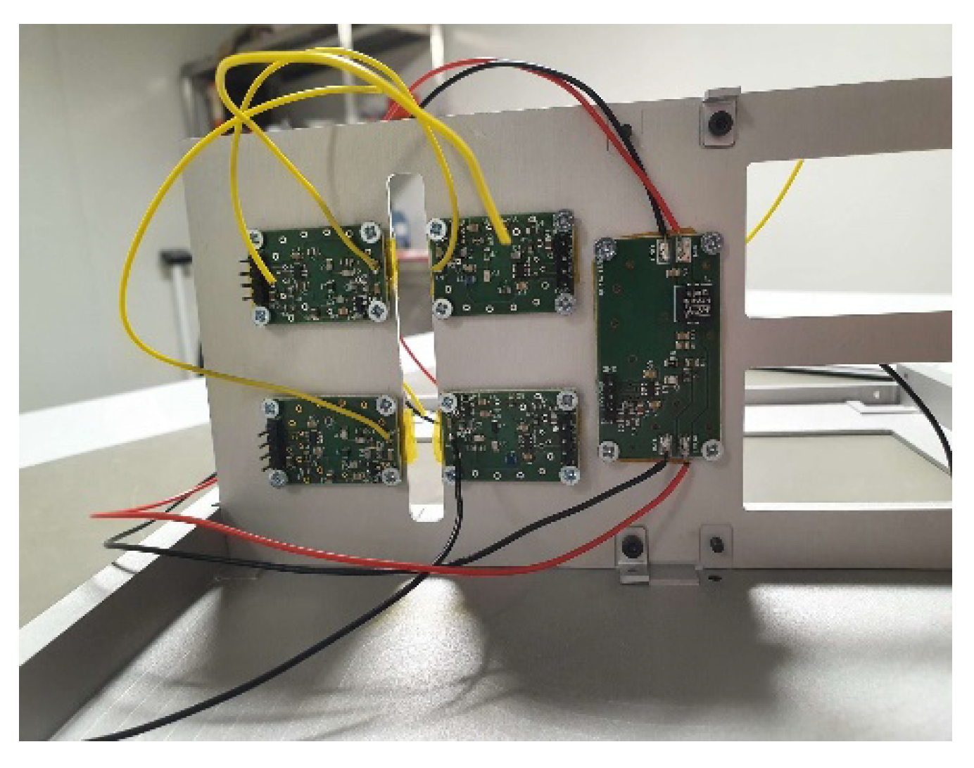
Eight micro-RF circuits measure the radiated emissions (
Figure 3). These circuits are based on simple antennas, a RF receiver made of a LTC5507 chip [
25], and pass-band filters calibrated in order to allow the frequency 1–10 MHz, 20–50 MHz, 100–200 MHz and 400–500 MHz. All the components are mounted on dedicated PCB sized 20 mm × 30 mm. Moreover, the pass band filter can be tuned on other ranges by changing few cheap, passive components, conferring high flexibility to these elements. Two boards for each range of frequencies are available and all the boards are installed on the bulkhead (four on the side towards the Service module and four towards the Propulsion Box).
The conducted emissions are measured using a dedicated circuit called Line Impedance Stability Network: it enables us to evaluate the radiative environment generated by the propulsion system along the power supplier line when it absorbs current. This circuit is again based on the LTC55x RF receiver and measures the noise on the absorbed with high accuracy (1 mA) and with a sample rate of 1 Hz.
A surface mounted MEMS triaxial magnetometer belongs to the Data Logging board. The output of the sensor is sent on the I2C bus. It allows us to monitor the Magnetic Field variations inside the CTP.
The High-Power Management System is made of a board (on the avionics box) and two PS battery packs that stay in the second unit of the service module.
The HPMS board hosts the Step-up circuit: it receives in input voltages in a range [10.5; 12] V from the PS-battery packs and provides in output 12 V regulated (with a minimum accepted level of 11.7 V) with a maximum current of 5A. This circuit is based on a switching DC/DC booster that has an efficiency of conversion higher than 95%. The board has also the battery recharger for PS battery packs: the BCR are the core of this element and can receive up to 32 W (16 V is the expected input voltage and max 2A has charging current) in order to minimize the recharging time (less than 6 hours for a complete recharge). PS battery packs provide up to 5.2 Ah at 12 V and their output is controlled by dedicated ‘Remove Before Test’ switches. Protection circuits prevent overcurrent, over voltage, or short circuits on the power bus; refresh fuses are added to each line, especially for the connection towards the propulsion system.
Acquisition circuits gather the measurements of the voltage and current and temperature for PS battery packs, step-up circuits, and the consumption on the 3.3 V and 5 V power bus lines. The output of the ADC is connected to the 104-pins bus to provide the sampled values to the SPI bus. These measurements allow for the estimation of the power consumption in any phase of the test, for different modes of operations of the propulsion system.
2.2. Representative of CubeSat Technology
The CTP’s structure is fully compliant with the CDS in terms of external geometrical interface and material (apart from surface coatings and treatments). The structure is constituted by two truss-like parts joined through four brackets and closed by panels. The internal layout can be adapted depending on the specific test. A bulkhead separates the propulsion box from the rest of the platform.
The Command and Data Handling, the Electric Propulsion System and the Communication System are representative of a traditional CubeSat bus: in fact, this technology has already been adopted for flown CubeSats (i.e., e-st@r missions) [
26].
Command and Data Handling (CDH) is based on an ARM-9 microcontroller that manages data and commands, time and synchronization, operations and on-board failures. SPI, I2C, and CAN buses together with serial lines guarantee the data exchange between the subsystems and non-volatile memories (i.e., Flash and an external SD card) store the data. The developed software is flexible enough to manage different communications types, also through specific protocols such as CSP, facilitating the interface with a wide range of miniaturized propulsion system. The CDH software manages onboard operations and communications, and even controls the propulsion system activity. Through the Interface Control Documents provided by the propulsion system developer, an independent, customized software module is implemented and then integrated with the entire onboard software. Moreover, the setups of the propulsion systems (i.e., the required power, the communication protocol, the list of commands, etc.) can be pre-loaded on the memory card or commanded through the Ground support system before and during the test sessions, conferring a high versatility to the CTP.
The Electrical Power System (EPS) board that regulates voltages, controls, and distributes the power to all the avionics systems and manages the avionics battery packs recharging. The Avionic Battery packs can provide up to 1.8 Ah @ 7.4V and are installed in the second unit of the Service module, near to the PS battery packs. They can be recharged in less than 2h and guarantee a long test duration (over 8 h without recharging) because of the low power consumption of the Avionics systems.
Two lines guarantee communications between the platform and operators: a wired serial line that directly connect the on-board computer with the Ground Support System and a RF link in UHF band. The latter is representative of a CubeSat communication system (COM SYS) and is the qualification model of the e-st@r CubeSat [
27].
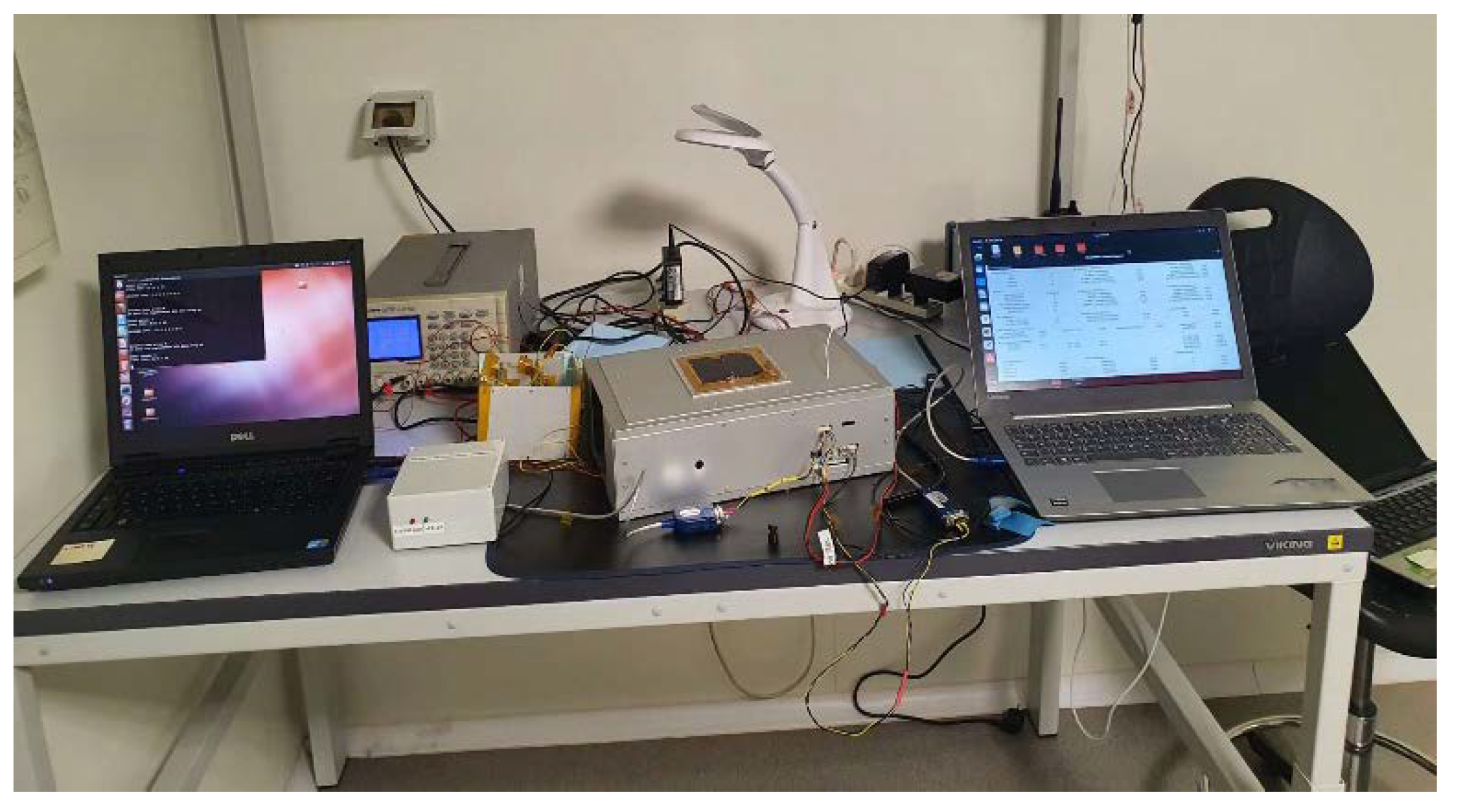
Figure 4 shows the detail of the Service module (
Figure 4a) with the avionics box on the left and the battery box (where the PS battery packs and the Avionics Battery packs are contained), and a view of the propulsion system box, ready to accommodate a propulsion system.
3. Validation of the Platform Capabilities
Within an exhaustive verification plan [
28] defined through an approach based on the tailoring of the ECSS, already adopted for the test campaign of e-st@r CubeSats [
29], some test campaigns were dedicated to validating the platform capability to provide the information necessary for the analysis of the mutual impact propulsion system/CubeSat tech. The validation includes:
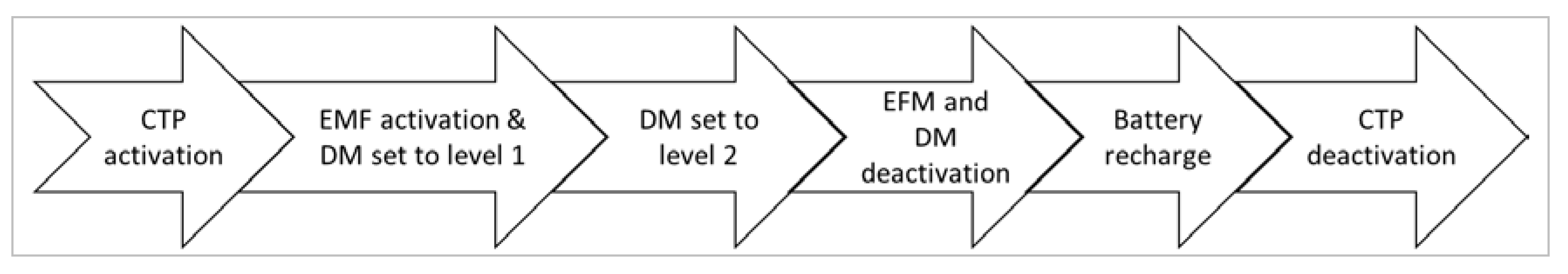
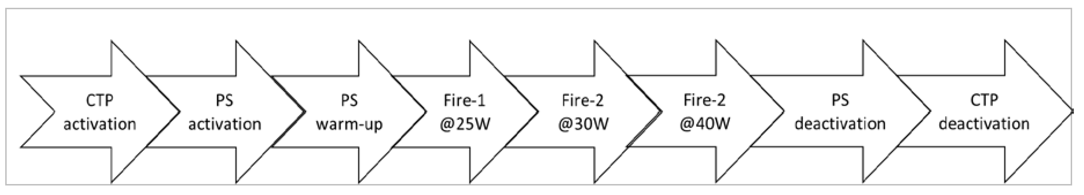
The functional test considered in this paper (see
Figure 6) foresees that the CTP is switched on and work in basic mode for 10 minutes, then output towards. The EFM of a propulsion system are switched on enabling the data exchange and the DM is set level 1 for 30 min. Then, the DM goes to level 2 for at least 1 hour. After the turn-off of the EFM and the DM, CTP remains active and the battery packs are recharged up to the complete recharging that brings the test to an end.
•
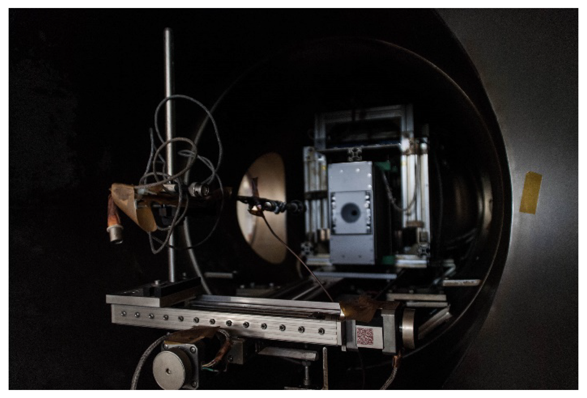
Environmental tests (in vacuum chamber) of the CTP equipped with a propulsion system [
30] (
Figure 7): a propulsion system is fully integrated in the Propulsion Box of CTP and the CTP installed in a vacuum chamber [
31].
Among the different test sessions, the results of the environmental campaign reported in this paper refers to the test sequence in
Figure 8.
3.1. Electrical Power
The electrical power distribution and the power consumption were assessed in two separate tests: one in laboratory conditions with a rheostat (instead a propulsion system) that provides a pure resistive load set to absorb 24W and 48 W, and the other in vacuum chamber with a propulsion system requiring different levels of power at 30W, 45W and 60 W.
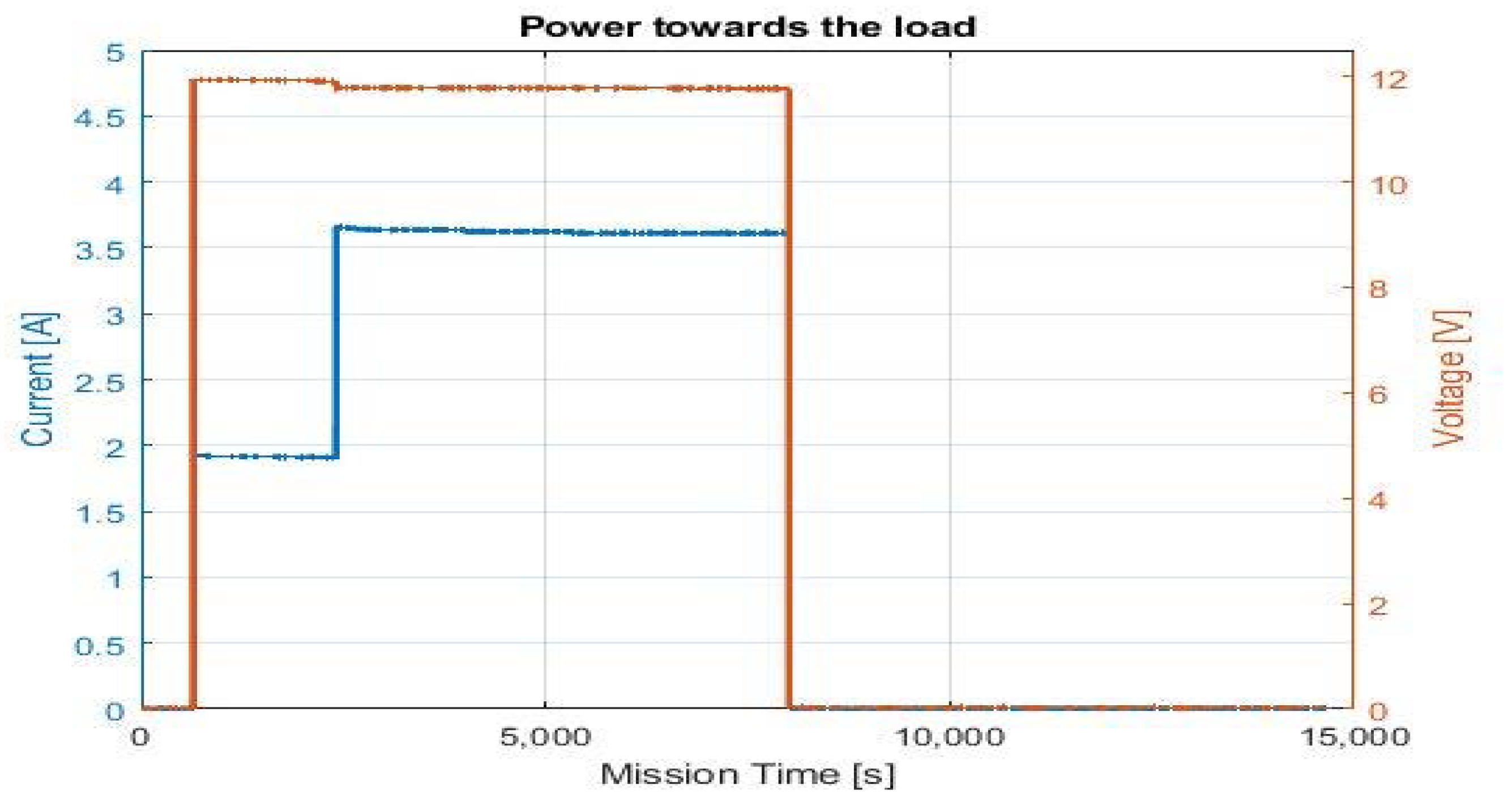
The electric power delivered by the HPMS to the DM is shown in
Figure 9. After 650 s, the PS was activated. The HPMS provided 1.91 A at 11.93 V for 30 min. The load level of the rheostat increased to 44 W, and the HPMS provided 3.62 A at 11.8 V for 90 min. These data demonstrate the capability of the CTP to supply the required power to the load without any noise and ripple, and no anomalies appeared.
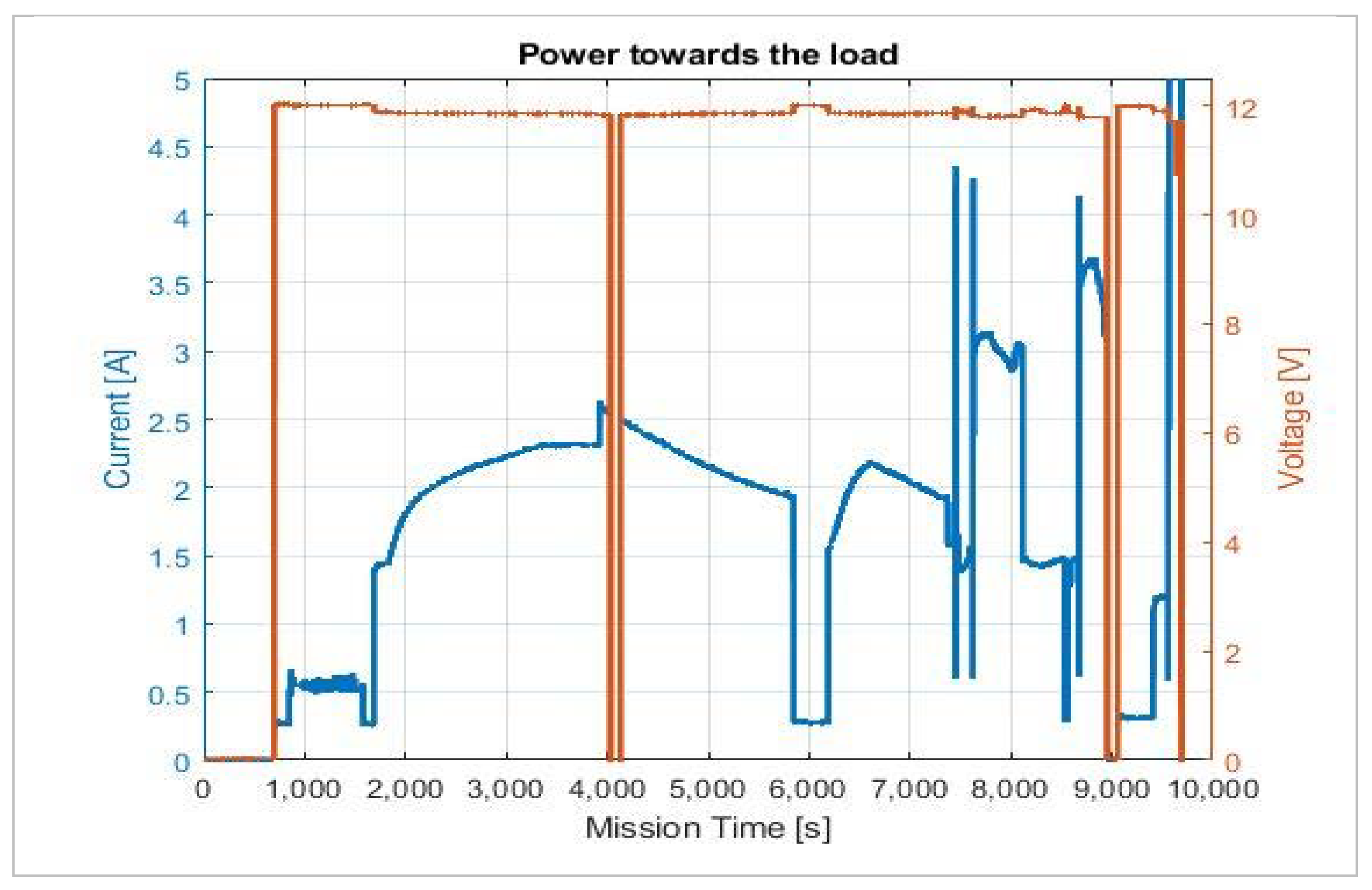
Figure 10 shows the trends of the current (blue lines) and the voltage (red lines) during the entire environmental test. After the reception of the command for the activation (after 600 s), the propulsion system enters the initialization phase (consumption of less than 0.3 A) that also includes the opening of a valve (consumption of about 0.5 A). Then, the PS enters in the pre-heating phase for 4000 s with a current consumption in the range 1.5 to 2.75 A. When the pre-heating ends, the system enters in the start automatic sequence that brings to first firing that requires a power of about 35 W. Then, the sequence continues with requests at 40 W and 60W. The power is correctly delivery also for the request of 60 W (the upper boundary condition for the HPMS) where a ripple on the voltage is observed without a loss of the power supply.
3.2. Thermal Environment
The thermal environment characterization passes through a precise calibration of the temperatures. The setup of this test is reported in figure. The sensors and part of the avionics (DLS and CDH board) are inserted in a thermal chamber with a perfectly calibrated thermocouple as the reference element.
The second relevant session foresees the CTP equipped with a helicon plasma propulsion system in a vacuum chamber.
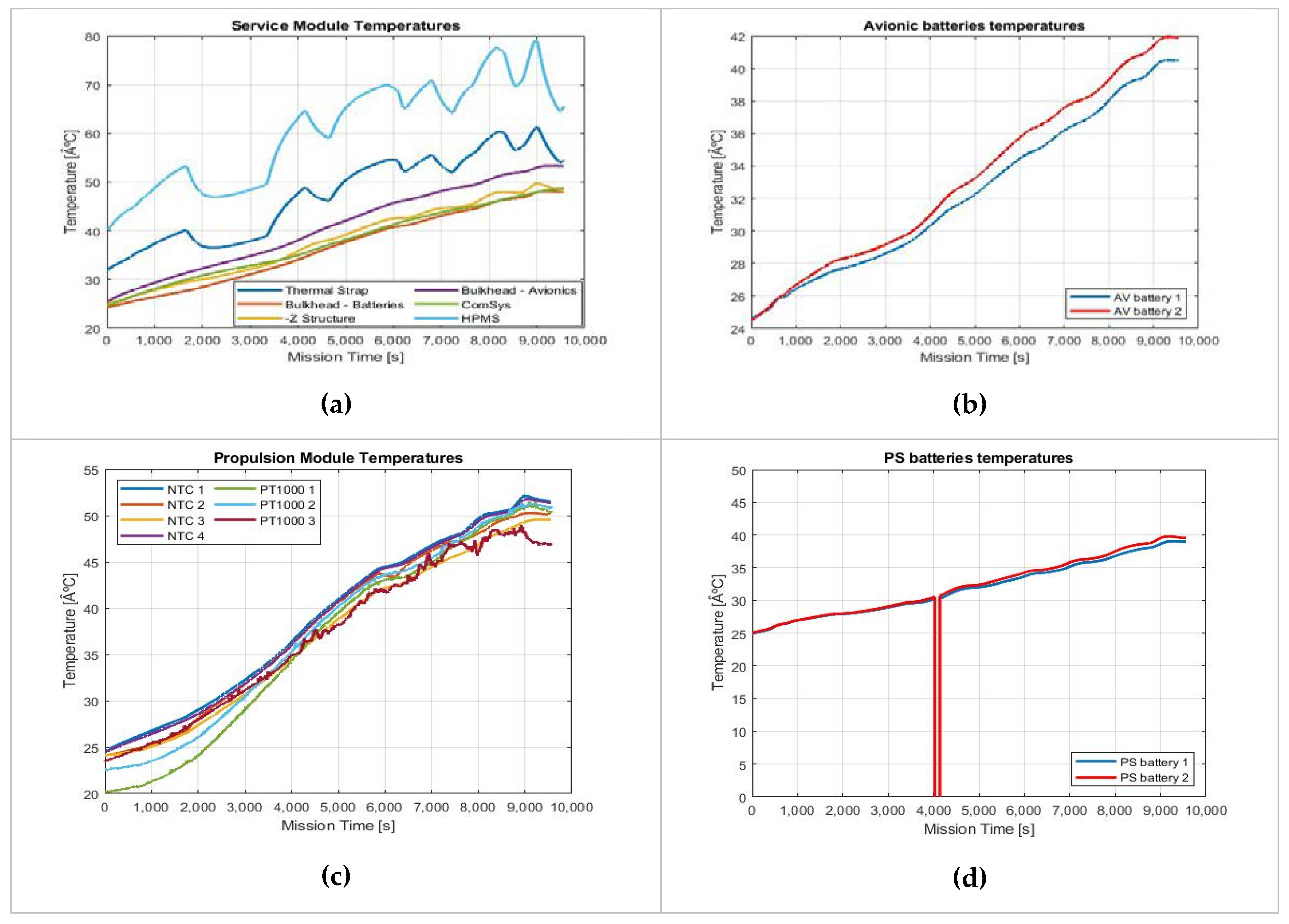
Figure 11 shows the trend of the temperatures in the Avionics Box (a), Battery packs (b) and (d), and Propulsion Box (c). The temperatures of all the components remain in the operative range. It is interesting to observe the behavior of the thermal strap mounted on the critical HPMS items: a temperature sensor is mounted on the thermal strap (blue line in
Figure 11a) and on the upper side of the HPMS (cyan line in
Figure 11a). A reduction up to 20 degrees is observed thanks to the thermal strap confirming that the solution is effective. Temperatures increase up to 55 degrees (
Figure 11c): NTC from 1 to 4 are installed in +Y, −Y, +Z −Z, respectively, and PT1000 from 1 to 4 are installed on the propulsion system case.
3.3. RF emissions and Magnetic Fields
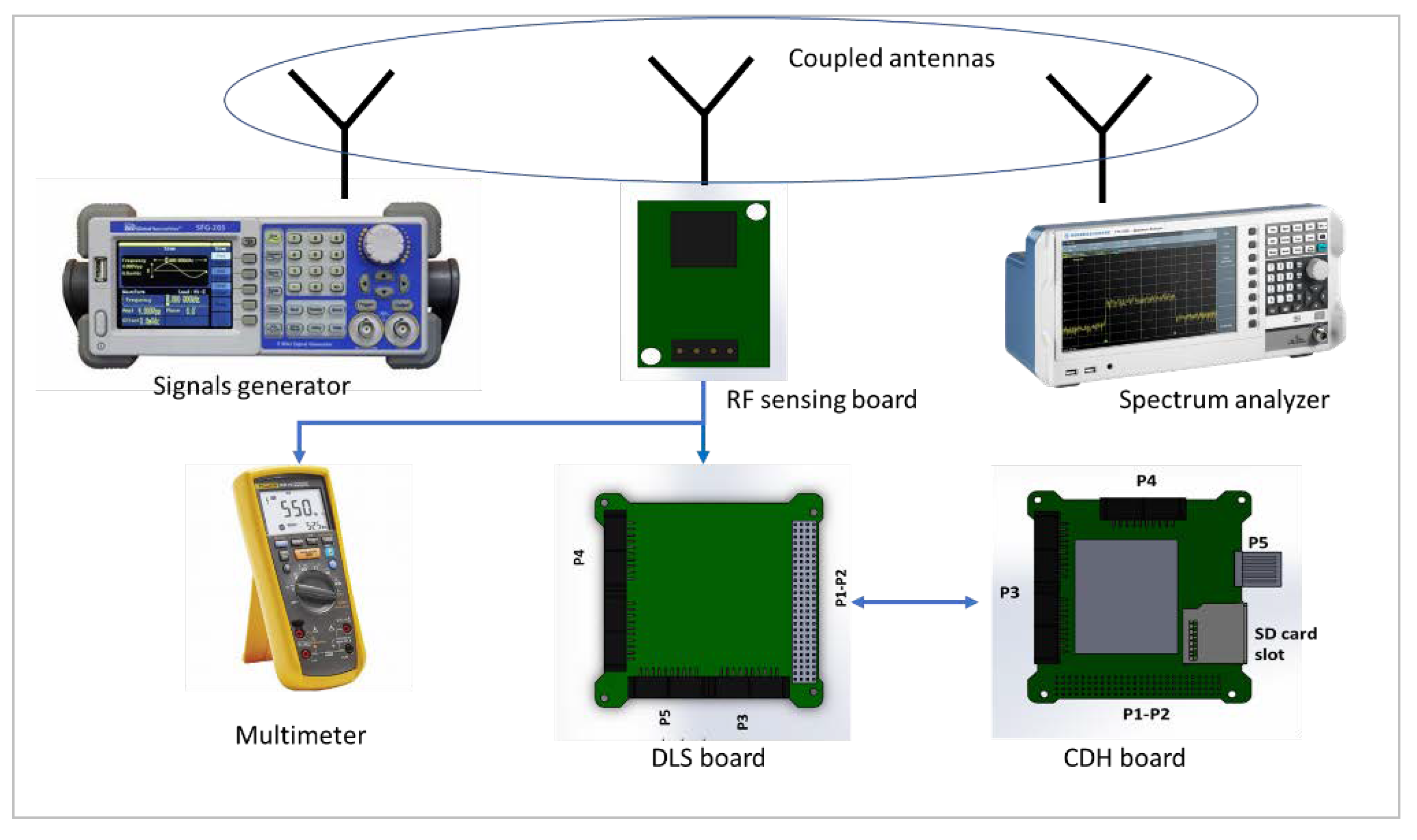
The assessment of the radiofrequency emissions is one of the most interesting and challenging aspects to be investigated. Many long sessions were necessary for the calibration and validation of the sensing circuits for both the radiated and the conducted emissions. The setup for the calibration (
Figure 12) consists of a signal generator and a spectrum analyzer beyond the board under test: the antenna of all the element are coupled, the generator provides a signal with different strength in the selected ranges of frequency, the analyzer shows the effective level of the signal and the RF sensing board provides in output a voltage values in the range from 0.2 V to 5 V proportional to RF emission. This voltage is acquired by the DLS board. The curve of the conversions is obtained through the datasheet information of the LTC55x chip. After the calibration, the boards are mounted on the bulkhead according to the assembly sequence.
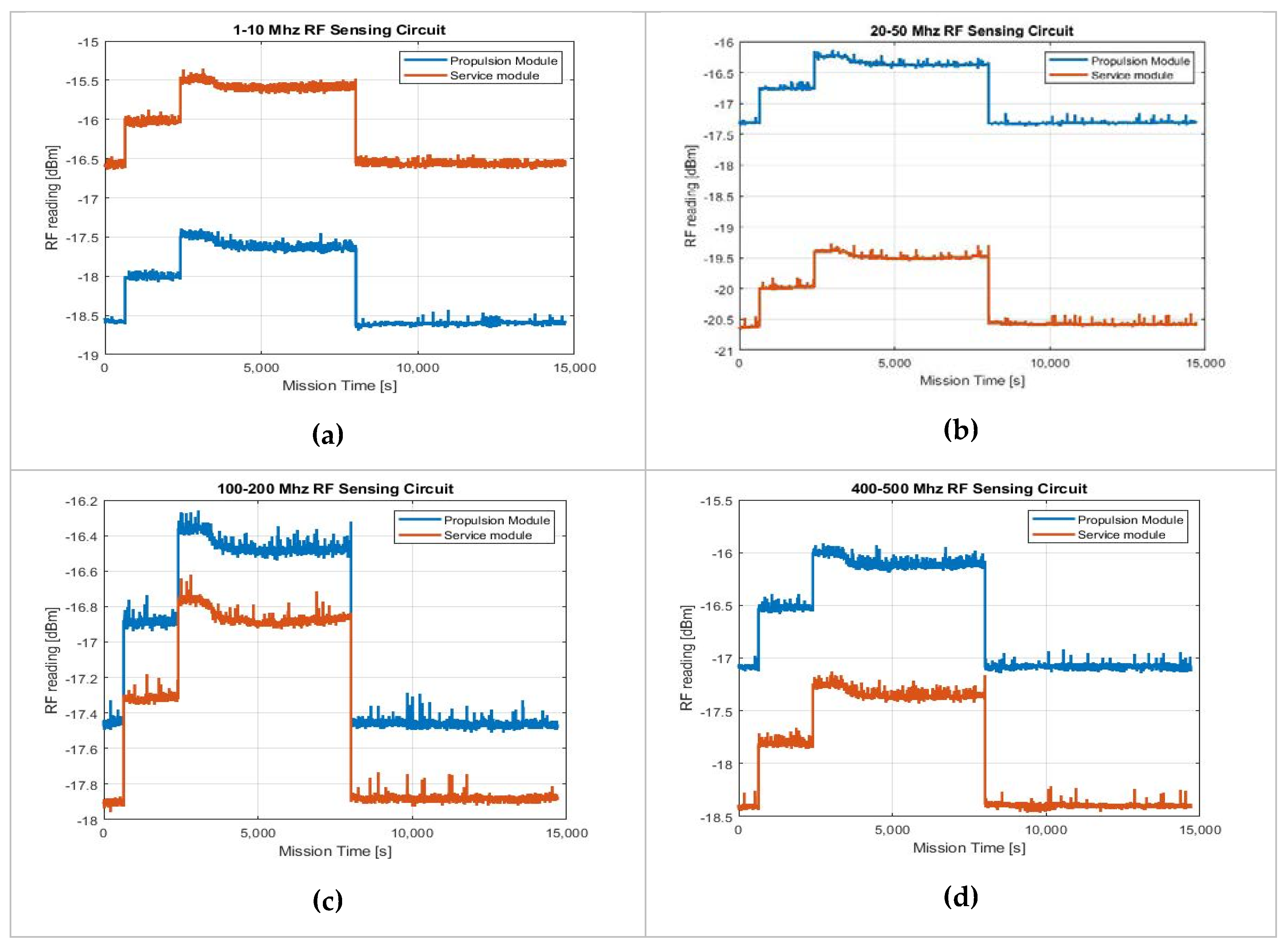
The observed emission during the functional tests (
Figure 13) had low intensity and the increments due to the change of electrical loads were negligible, as expected, due to the pure resistive nature of the load. However, the capability of the system to acquire the data on the radiated emission was confirmed.
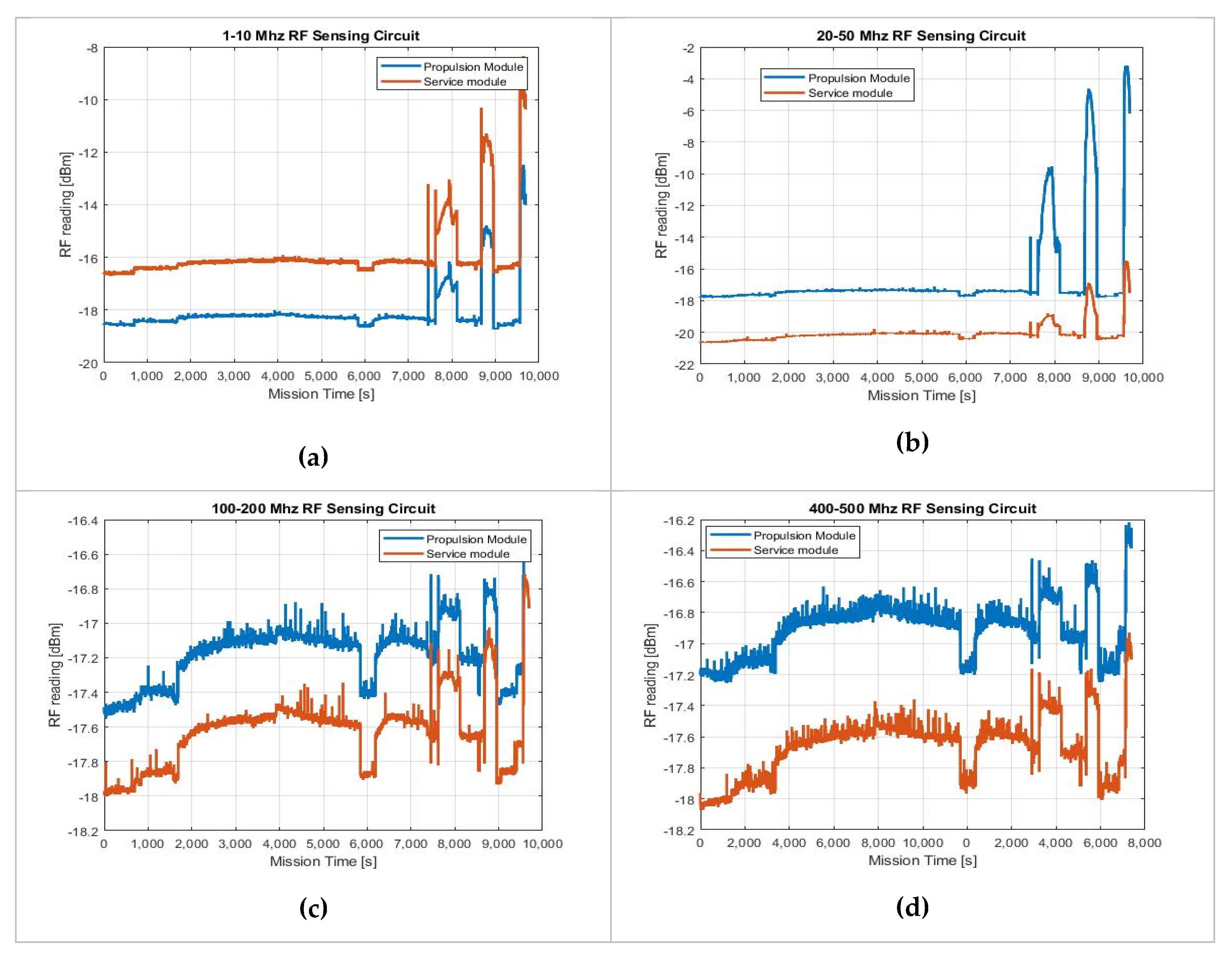
Another session for the validation of the board devoted to reveal the RF emissions are the environmental tests, the results of which are reported in
Figure 14. The operations of the propulsion system generate an increment of the noise levels in particular in the range of 1 to 10 MHz and 20–50 MHz mainly due to the plasma ejection. This increment is observed both from inside the propulsion box and inside the avionics box. In particular, the most relevant increment of 15 dBm is observed in the range 20–50 MHz. These emissions do not compromise the operations both of Regulus and the CTP during the entire test: no losses of communication and no failures of switching of the step-up HPMS are observed.
The variations observed by the 100–200 MHz and 400–500 MHz boards are negligible: for the latter, it means that the RF transmission does not generate a significant emission inside the platform and does not affect the onboard operations because the RF power passes through the main lobe of the antenna and the other spurious emissions and side lobes are very low.
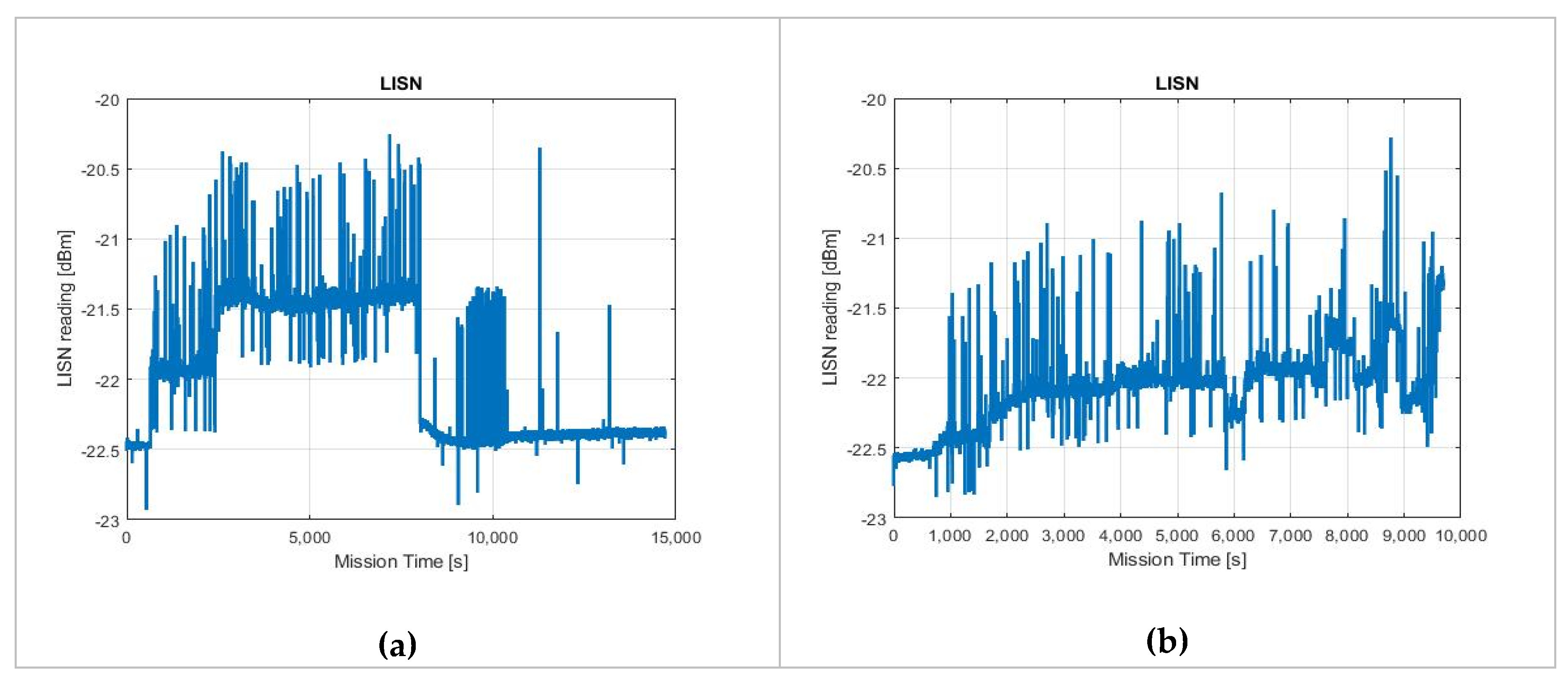
The conducted emissions are measured through the LISN circuit that is located between the HPMS board output and the propulsion system input power line. The characterization is made with the same setup shown in
Figure 15, while the results of the functional and environmental tests sessions are reported in
Figure 15. Both in the case of pure resistive load and in the case of a real propulsion system the emissions variations are less than 1 dBm and the absolute values show that this emission are negligible for both the test configurations.
The magnetic field is revealed by the magnetometer on the DLS. The calibration of the sensor output is made through the datasheet and confirmed using the calibrated magnetometer of an MTI inertial sensor [
32] available in the Politecnico di Torino laboratory.
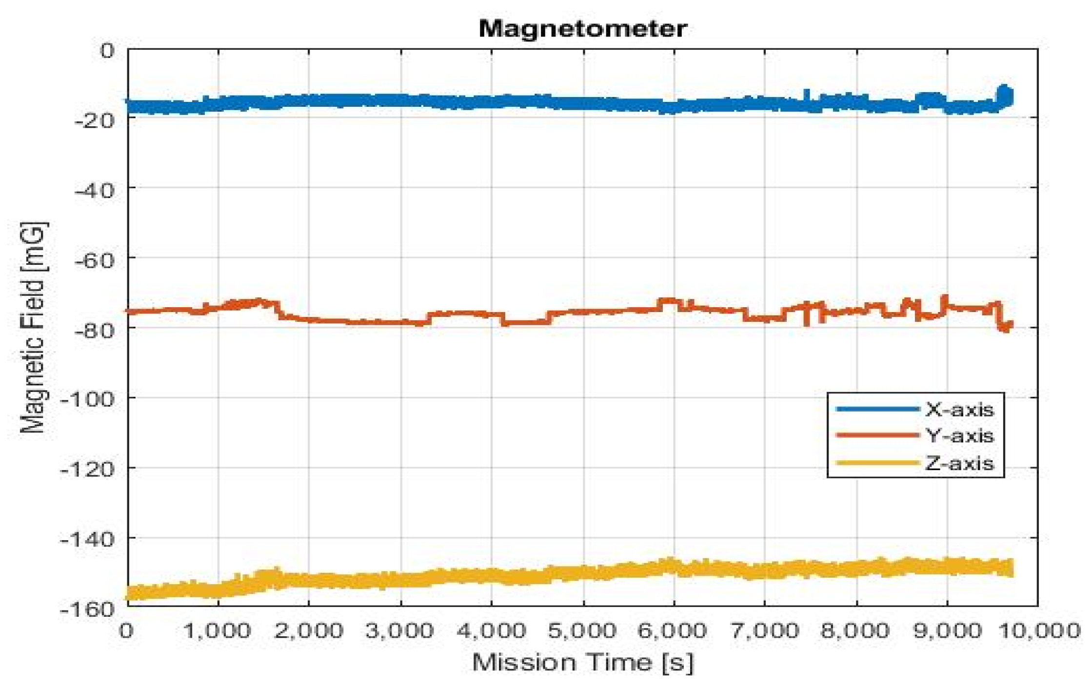
The results of the environmental test are reported in
Figure 16. The Magnetic Field remained quite constant along the three main axes of CTP. The values are compatible with Earth Magnetic Field, demonstrating that the generated magnetic field emission inside the CTP is negligible and the generated magnetic dipole can be compensated by the state-of-art actuators of a CubeSat.
4. Discussion
The test platform is fully compliant with a 6U CubeSat platform: the structure is compliant with the CubeSat Design Specification, the avionics’ performance is confirmed in terms of low power consumption (less than 5 W), capability to transmit and receive data and commands, and capability to manage the on board operations. This means that the adopted technologies are representative of a real spacecraft. Moreover, the functional tests demonstrate that:
the PIS can deliver a high amount of power for the operations of the propulsion system under test;
the generated heat by the avionics is managed by the thermal strap guaranteeing that the system remains in the operative ranges of temperatures;
the RF emission due to the avionics system is very low when no propulsion system is installed.
For the topic of this paper, the assessment of the mutual impact between miniaturized propulsion systems and CubeSats is supported by the measurement and the relative analyses enabled by the Propulsion Interface System. After the calibration and the functional test sessions, the environmental tests demonstrate the capability of CTP to successfully host a real and consolidated propulsion system. Moreover, the test campaign results provide valuable confirmations and highlighting possible issues that are very useful for the future developments of the propulsion system and the improvement of the CTP:
the radiofrequency emissions and the generated electro-magnetic fields can be relevant when the plasma is generated for high power thrust of an electric propulsion system. However, noise values under to the 0 dBm does not affect the onboard functionalities;
the noise generated by the propulsion system on the power line is negligible: it prevents undesired ripples in nominal conditions and preserve the Power System components to failure;
a high request of electrical power can generate a relevant increment of the temperature on and around the boards and battery packs. The heat should be managed by CubeSat developers especially when the propulsion system is active, and the batteries are under recharge. Even so, part of the delivered power for the propulsion system operations is converted in heat along the structural elements that connect the propulsion system to the rest of the platform. Also, this increment seems relevant especially in vacuum conditions. All these observations deserve attention in order to consider an appropriate Thermal Protection/Control System for CubeSats equipped with propulsion systems.
Table 1 summarizes the main features of the CTP and the main achievements deriving from the validation campaign.
The obtained results validate the CTP and make it a valuable instrument to support the verification of CubeSat equipped with propulsion systems providing unprecedented information (that can be merged with the instruments already available for stand-alone tests) to characterize the environments generated by the interactions between different technologies and provide the elements to successfully interface a propulsion system with a CubeSat.
5. Conclusions
Miniaturized propulsion systems have already achieved important results at the component and subsystem levels and now are required to increase the level of readiness for future CubeSat missions demonstrating their integrability with the existing small satellites technology. In order to fill the gap between propulsion solutions and traditional CubeSat technologies, the presented work provided an effective solution to show that the new propulsion systems are not a threat for the other onboard subsystems and that simple but reliable technologies can enable an easier integration and verification for a CubeSat equipped with a propulsion system.
The CubeSat Test Platform is a valuable instrument to increase the level of readiness of a new technology and consolidate the capabilities and robustness of already available CubeSats elements. The platform supports, and often allows for functional and operational tests to be conducted (both in laboratory and even, in vacuum conditions) for the entire system, gathering information about electromagnetic compatibility, thermal environment induced by the operations of the subsystems (specifically, of the propulsion system), and power consumption. This information combined with the measurements obtained by instruments outside the CTP opens an unprecedented framework both to developers of propulsion systems and CubeSat integrators, thus anticipating/revealing possible problems and misbehaviors generated by the operations conditions and/or certifying that the integrated system (platform +propulsion system) works properly, reducing the time-to-market of the products. The platform enables the propulsion system to operate as it does in the orbit condition without the support the ground support equipment and allows for an increase of the Technology Readiness Level and Integration Readiness Level of the propulsion system.
Future works of the project aim at enlarging the set of measurements for the assessment and enabling the possibility to perform mission tests (beyond the tests already presented in this paper). Improvements in information can be achieved from the increment of sensors/devices and tools. For example, information can be obtained about the chemical contamination (that could be made only in post-processing now by analyzing the CTP surface with specific ground support equipment). On the other hand, the development of GSE, such a mission simulator with a sun-light generator, has already begun, which enables the possibility of simulating the behavior of the platform along the orbit.


