1. Introduction
The technology of air-bearing platforms for emulating spacecraft orbital maneuvers has been evolving over the years. Some platforms specialize in attitude dynamics by allowing three-axis rotation through a spherical air bearing [
1]. Many other platforms, however, specialize in operations that can combine translation and orientation. Most of the platforms for combined operations include an arrangement of three planar air-bearings that allow for motion exclusively on the horizontal plane and integrate some sort of compressed air or cold gas propulsion system for steering the vehicle. A recent example of such kind of platform can be found in [
2]. However, some designs are capable of performing experiments in five degrees of freedom [
3] or even six degrees of freedom [
4]. Despite the fact that many such platforms have in common the use of inertial measurement units and external metrology systems for tracking purposes, the most notable differences are still found in the additional sensors used for position and attitude determination. Examples of such diversity of sensors include lidars [
3], ultrasound beacons [
5], fiber-optic gyroscopes [
6], camera-based vision systems [
7], star trackers [
8], Microsoft Kinect motion systems [
9] and indoor GPS receivers [
10].
These platforms are commonly used to study coordinated operations and proximity maneuvers. Some remarkable examples of the operational scenarios that were experimented with air-bearing platforms in the literature are docking [
11,
12], grasping [
13,
14] and formation flying [
15,
16].
To perform such experiments, teams rely on several specimens of the same platform, or with very similar functions. However, research groups may not have the resources to build several platforms, the space to perform coordinated operations may be too small, or the teams may even be interested in experimenting with the platforms of other laboratories. Federated remote laboratories are experimental setups that can be operated remotely, where access may be granted to external institutions [
17]. Different architectures of federated remote laboratories have been already used successfully for performing tests with industrial purposes [
18,
19] and educational purposes [
20,
21,
22]. These tools can help researchers who share their facilities to create more sophisticated experiments by combining the resources of several laboratories.
The main problem of connecting remote laboratories for performing experiments of coordinated maneuvers is the effect of delays on the dynamics of the platforms. Delays in the spacecraft avionics influence the control loop and can potentially cause instabilities if they are long enough [
23]. In real orbital scenarios, control delays may also be influenced by the latency of the communications between spacecraft performing coordinated maneuvers [
24]. This problem is exacerbated when the spacecraft is outfitted with any flexible appendages, such as booms, solar panels, or large antennas.
This is because the ensuing lower natural frequencies can also interfere with the execution of the control system [
25]. Solutions to the problem of control delays have been proposed theoretically in the literature with many applications: increasing the robustness of the control laws [
26,
27,
28], compensation of communication impairments [
29,
30], decentralization of the decision-making process [
31,
32], et cetera. Nevertheless, more effort on the practical implementation of such algorithms is still needed.
This article provides an approach for performing coordinated experiments at two remote laboratories. The problem of defining an accurate common time reference that all parties can use reliably must also be tackled. Both the delay and the estimation of the clock offset are crucial for performing time synchronization between two agents. This can be achieved in a real scenario, among other approaches, by signal processing methods [
33,
34] or by assuming a common global time reference, such as the Global Navigation Satellite System (GNSS) [
35]. Unlike these examples, the proposed approach does not depend on third-party systems, and the protocol is implemented on the application layer, making it robust and easy to adapt to different communication methods.
However, other novel space control methods, such as electromagnetic docking [
36,
37], may receive little benefit from the presented setup. The electromagnetic docking technique involves a set of small spacecraft performing proximity operations that can mutually influence their pose using the homonymous forces. This technique implies the physical presence of at least two objects in the same vicinity, while the scope of the experiments in this article is quite the opposite.
The article starts by introducing the experiment setup in
Section 2. The descriptions of the platform in Kiruna, KNATTE, and the platform in Rome, PINOCCHIO, are provided in this section. Additionally, the description on how all devices are connected within each laboratory and between them over the internet is also provided. Then, the paper presents the proposed coordination protocol in
Section 3. The description of the protocol includes the theoretical perspective on how the synchronization algorithm works and the practical implementation, with the specific applications implemented in Simulink and the configuration that we used later on.
Furthermore, the paper discusses the results of performing a first series of validation simulations in
Section 4.
Section 5, on the other hand, discusses the results of experiments involving physical coordination maneuvers performed with both platforms. The paper ends in
Section 6 with a discussion of the most significant findings and possible future developments for this research.
2. Experiment Setup
Two similar laboratory setups were prepared at two remote locations. On one side, the KNATTE vehicle [
38] operates in the Nanosatellite lab at Luleå University of Technology in Kiruna, Sweden. On the other side, an improved version of PINOCCHIO [
39,
40,
41] operates in the GNC lab at University of Rome La Sapienza in Italy. Both vehicles need to coordinate their activities to perform concurrent experiments.
2.1. KNATTE
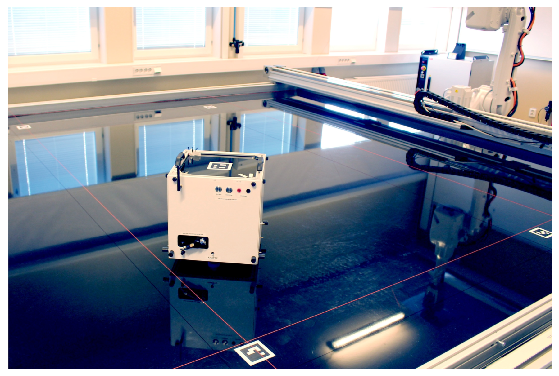
The Kinesthetic Node and Autonomous Table-Top Emulator (KNATTE) is the floating platform developed at Luleå University of Technology. It is a three degree of freedom frictionless vehicle that can move and rotate freely in the horizontal plane within the limits of the frictionless table provided for that purpose, see
Figure 1. The aim of the platform is to simulate orbital conditions for guidance, navigation and control experiments and also to serve as a standalone tool for testing software and hardware.
The construction of KNATTE consists of a cubic frame of 300 mm sides. It has 10 kg of mass and a moment of inertia of 0.160 . The KNATTE vehicle includes a pneumatic system that powers the three air-bearing pads that create the frictionless effect as well as the eight thrusters distributed around the perimeter of the vehicle. The propulsion system of KNATTE can exert a maximum thrust of 0.64 N and a torque of 0.102 Nm although it is currently set to operate at 0.20 N and 0.032 Nm, respectively.
Additionally, a miniature personal computer running MATLAB and Simulink is the centerpiece of the avionics. The computer digitizes the control signals for each thruster via an input/output device that controls each solenoid valve through its corresponding driver. Position and orientation data is extracted from an Inertial Measurement Unit (IMU) at 100 samples per second. Additionally, the platform relies on the tracking data provided by an external computer vision system at 20 samples per second for reliability.
The table is a metallic construction that supports a flat and smooth surface of epoxy in which KNATTE can move with virtually no friction. Despite the rigidity of the structure, the surface develops anomalies over time, which induce external forces to the platform during the experiments. The effective area in which KNATTE can move without collisions is 3.1 m × 3.4 m. However, the current setup of the computer vision system only covers an area of 3.0 m × 1.7 m over the table, and the operations should be restricted to that area for maximum reliability.
2.2. PINOCCHIO
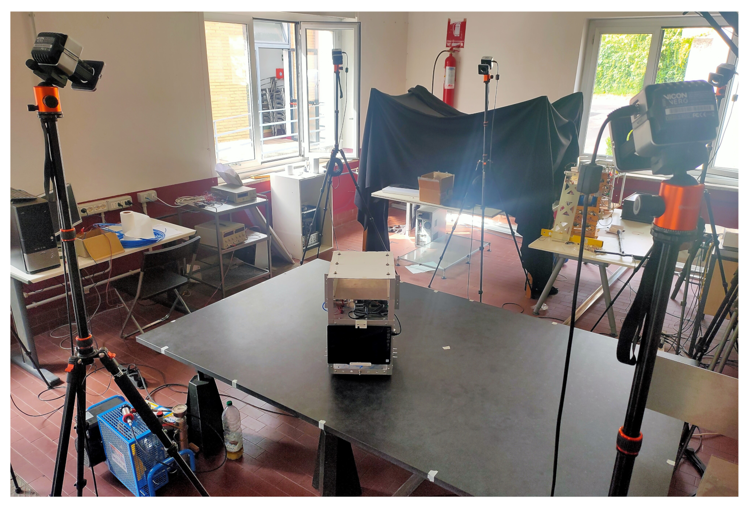
The Platform Integrating Navigation and Orbital Cooperative Control Housing Intelligence Onboard Testbed (PINOCCHIO) at the Sapienza University of Rome is a custom-built floating platform to replicate the dynamic behavior of a satellite for studying and testing autonomous operations in space. It can be used for the simulation and testing of attitude and position control laws on very flexible satellite too.
Figure 2 shows a photo of the PINOCCHIO platform bus on a granite table.
The free-floating platform is realized with a pneumatic suspension system, which enables a two-dimensional test of complex space operations, such as rendezvous and docking. The platform is equipped with IMU and actuated via cold gas thrusters. The platform produces a reduced-friction environment by expelling air from three planar air bearings to generate an air layer between the flat floor and the test platform. This allows the platform to move in three DOF, two lateral and one rotational, with minimal friction on a flat floor. The chassis of the platform is designed in order to fulfill to main requirements:
- (a)
to be so rigid that the effect of its elasticity is negligible and
- (b)
allowing a reconfiguration of the appendages on the platform.
The structure of the floating platform is made of aluminum alloy. The overall dimensions of the structure are 300 mm × 350 mm × 480 mm. The principle that guided the design is the idea of modularity: the structure consists of three compartments, and each of them may be used for a specific purpose. The lower compartment (300 mm × 350 mm × 280 mm) houses the pneumatic system, while the second floor (300 mm × 350 mm × 100 mm) hosts the electronics: sensors, Arduino boards and wiring. The third floor hosts the electronics needed to drive additional payloads. The total weight of the platform is currently 16.55 kg, and the estimated moment of inertia is 0.4002 kg· m (around the vertical axis, perpendicular to the table passing through center of mass.
The inertia properties of the platform are reported in
Table 1 while the navigation and control performance, as measured in the commissioning campaign, are reported in
Table 2 and
Table 3, respectively.
2.3. Guidance, Navigation and Control Architecture
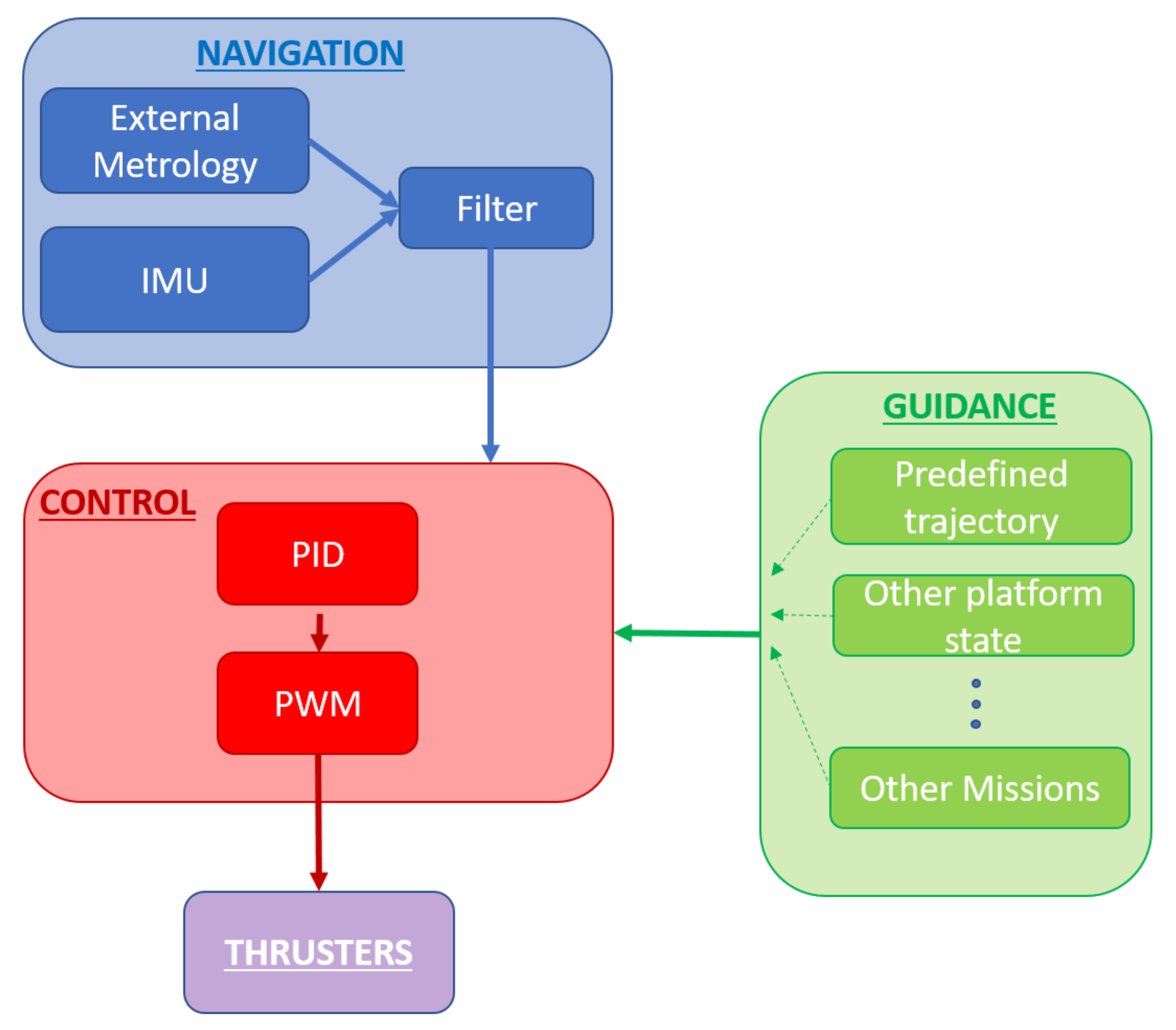
Both platforms, KNATTE and PINOCCHIO, adopt a similar guidance, navigation and control (GNC) architecture as shown in
Figure 3.
To estimate the platform state, the navigation block uses a Kalman filter that blends the IMU measurements with the external metrology measurements, i.e., the six Vicon cameras for PINOCCHIO and a single camera for KNATTE. The guidance block is different for every agent. In the attitude tracking test detailed in
Section 5, one of the platforms (KNATTE) follows a predefined trajectory as a leader, while the other one (PINOCCHIO) acts as a follower acquiring and attempting to track the incoming data from the inter-platform communication channel.
The control algorithm selected for this research was kept as simple as possible because the focus was on the communication and interoperability problem rather than optimizing the performance. Therefore, a Proportional–Integral–Derivative (PID) controller was selected. For the attitude tracking case, the control error (
e) in Equation (
1) is the difference between the heading angle (
) at a specific moment (
t) and a reference heading (
) given by the guidance block.
The PID algorithm provides a control law as described by Equation (
2).
where
,
and
are, respectively, the integral, proportional and derivative gains. The continuous control torque (
) obtained in this way must be modulated since the propulsion system can only be commanded on or off. Hence, a Pulse-Width Modulation (PWM) algorithm was implemented for this purpose, giving a binary signal to the actuators.
2.4. Network Setup
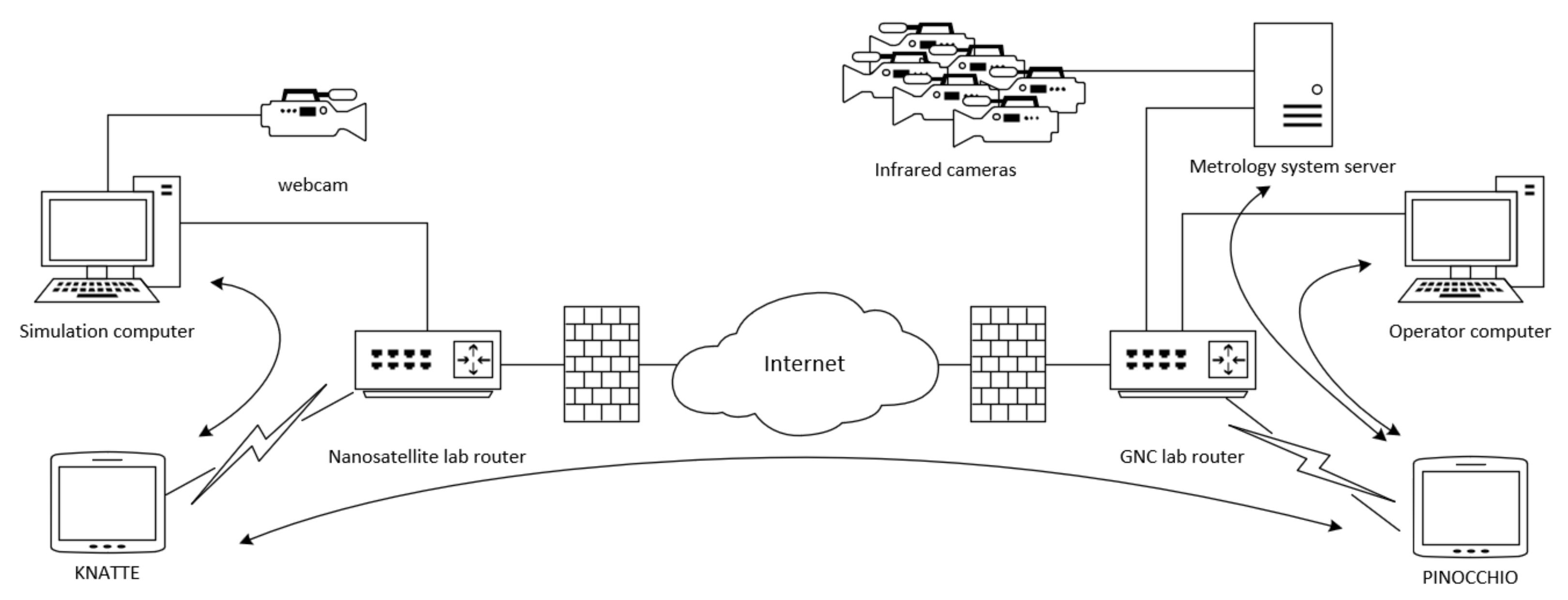
Both platforms, KNATTE and PINOCCHIO, are connected through the internet via the infrastructure that each university provides as shown in
Figure 4. As is the case of this configuration, institutional network infrastructures are often protected with stateful firewalls. A stateful firewall blocks all incoming packets for all ports that are not explicitly allowed by default but allows packets that are sent in a response to a request. Hence, incoming packets can reach their destination port without changing the security policy of the firewall if the host keeps the connection established by sending packets within the flow timeout period.
The protocol implemented in
Section 3 has an active and a passive process. The behavior of the stateful firewall was problematic in our case because the passive process expects a request packet before processing and sending any data out. This problem can be solved by giving exceptional access to certain IP addresses for passing the laboratory’s firewall. However, this is not always possible for large institutions with strict network security policies like ours. The alternative solution that we opted to is to force a packet out at the beginning of the experiment. After the first packet is sent, the firewall will keep the port open and passive process can remain expecting incoming requests as long as they come within the timeout period.
All experiment devices in the Nanosatellite lab were connected to the same wireless local area network (WLAN) through a router that also provides internet access. The devices in the GNC lab in Rome were interconnected in an analogous manner. All devices connected to one router shared the same public IP address. Therefore, in order to refer to specific ports at specific devices within a WLAN, the router was configured by port forwarding to redirect specific ports of the public IP address to ports of the various local IP addresses. In this configuration, only KNATTE and PINOCCHIO are connected through internet. All other components in the corresponding WLANs, such as the simulation computer in Kiruna or the operator computer and the metrology system server in Rome, do not need to have their ports forwarded.
3. Coordination Protocol
Coordination between both agents can happen only if both agree on a reference for space and time. For the space reference, we pretend that both agents are in the same vicinity and the frame of reference of one metrology system can be transformed to the other by simply applying a transformation matrix. In the case of time, we cannot guarantee that all computer clocks involved in the experiment are synchronized to the same UTC reference nor to a suitable degree with the available tools. For that reason, a specific synchronization protocol was implemented for the scope of such experiments.
3.1. Time Synchronization
The synchronization algorithm implemented in the experiments is an adaptation of the Simple Network Time Protocol [
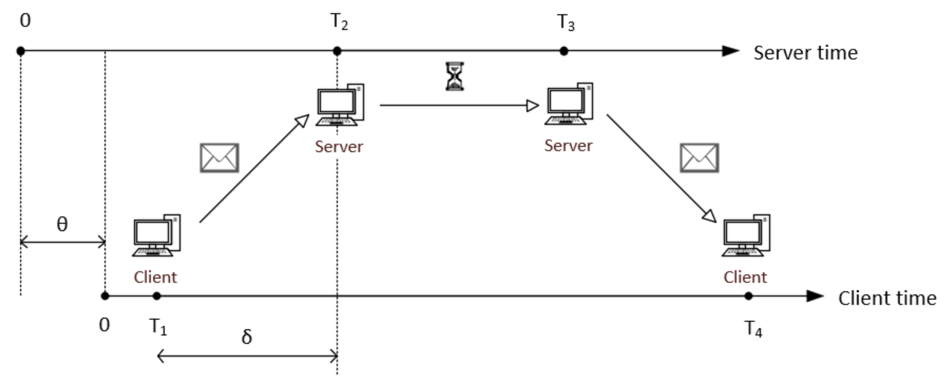
42]. The original application was proposed to synchronize a distrustful clock to a reliable clock keeping a universal time reference. The implementation of such protocol is asymmetrical, meaning that the agents do not share the same amount of information. The client needs four timestamps to estimate the time differences between client and server, but only the first three are known by the server. The synchronization protocol follows the sequence of events as depicted in
Figure 5. The protocol begins when the client agent sends a request to the server. The server records the time when the request is received. After some waiting time, the server sends the reply back to the client. Finally, the client can process all data.
The timestamps through happen in chronological order as in the list and are used by the client agent to calculate the synchronization parameters.
Time according to the client’s clock at which the client sends the request.
Time according to the server’s clock at which the server receives the request.
Time according to the server’s clock at which the server sends back the reply.
Time according to the client’s clock at which the client receives the reply.
However, the proposed protocol focuses on the administration of the relative clock differences rather than trying to follow a universal reference to allow information symmetry between the agents. Hence, all devices can start their clocks at arbitrary moments, but their frequencies must be stable in order to have meaningful results over extended periods of time.
In the implementation of such a protocol, not only every agent acts as a client requesting coordination data at the configured rate, but also responds as a server for the requests of the other agent. Additionally, provided the time that the server requires to dispatch the client’s request (<1 ms) is much smaller than the information travel time (10 ms), we can consider that and happen at the same moment. Therefore, the proposed protocol only uses , and for simplicity.
The one-way delay (
) is the average time for a message to travel from one agent to the other and can be estimated with Equation (
3).
The clock offset (
) is the time difference between the client and the server clocks with respect to the client’s clock, and can be estimated by Equation (
4).
For the experiments, we arbitrarily picked a leader agent to use its clock as reference. That means that the reference simulation time (
) is considered equal to the leader’s execution time (
). The symmetrical protocol still allows the leader to know the delay between agents.
Then, the follower agent can calculate the simulation time by adding the clock offset to its execution time. Clocks are not completely stable, and other spurious effects can also happen in the network. Therefore, the estimation of the clock offset is subject to fluctuations. The experiment is configured to start operations after 10 s of the reference simulation time. Until that moment, the follower agent has the opportunity to measure the clock offset in several occasions and average its value to use it as a constant parameter during the operations as in Equation (
6).
Other methods of finding the central tendency of the offset, such as the median value, may be more adequate than the arithmetic mean. The median value is theoretically less affected by outliers and skewed data than the mean. However, we opted to use the mean because the distribution of the offset is not skewed, and the effect of possible outliers is insignificant over the 10 s sample, giving identical results for both methods. Consequently, the simplicity of the algorithm to calculate the mean in Simulink compensates the numerical stability of calculating the median in this case.
3.2. Data Transfer
The experiment uses the User Datagram Protocol (UDP) through the Internet Protocol (IP) to send data packets between the agents. Such protocols allow for simple configuration of the communication channel with asynchronous messages. The UDP protocol communicates faster and requires less computer resources than other internet protocols, such as the Transmission Control Protocol (TCP). That makes it a better option, particularly for the synchronization problem. However, the UDP protocol does not guarantee the order or the arrival of the packets. These are minor inconveniences that were mitigated by sending data packets regularly and by the content of such packets.
Two channels were opened between the two platforms. On one channel, the follower sends request messages to the leader, and the leader replies back with time and tracking data. On the other channel, the roles are reversed. Hence, the coordination protocol can allocate more agents by adding UDP ports to the software.
In order to solve the coordination problem, the data packets contain not only information about time synchronization but also information about the localization of the agents.
Figure 6 shows how the data are packed and sent by any of the agents when acting as a server. Additional information for the identification of the agents is not required because the header of UDP packets already includes the source and destination of those packets. Particularly, the request packet of either agent consist of one double float variable,
, sizing 8 bytes. The reply packet consists of eight double float variables, i.e., the time
from the request packet, time
, position
x, position
y, heading
, speed
, speed
and angular rate
. The reply packet has 64 bytes of data in total.
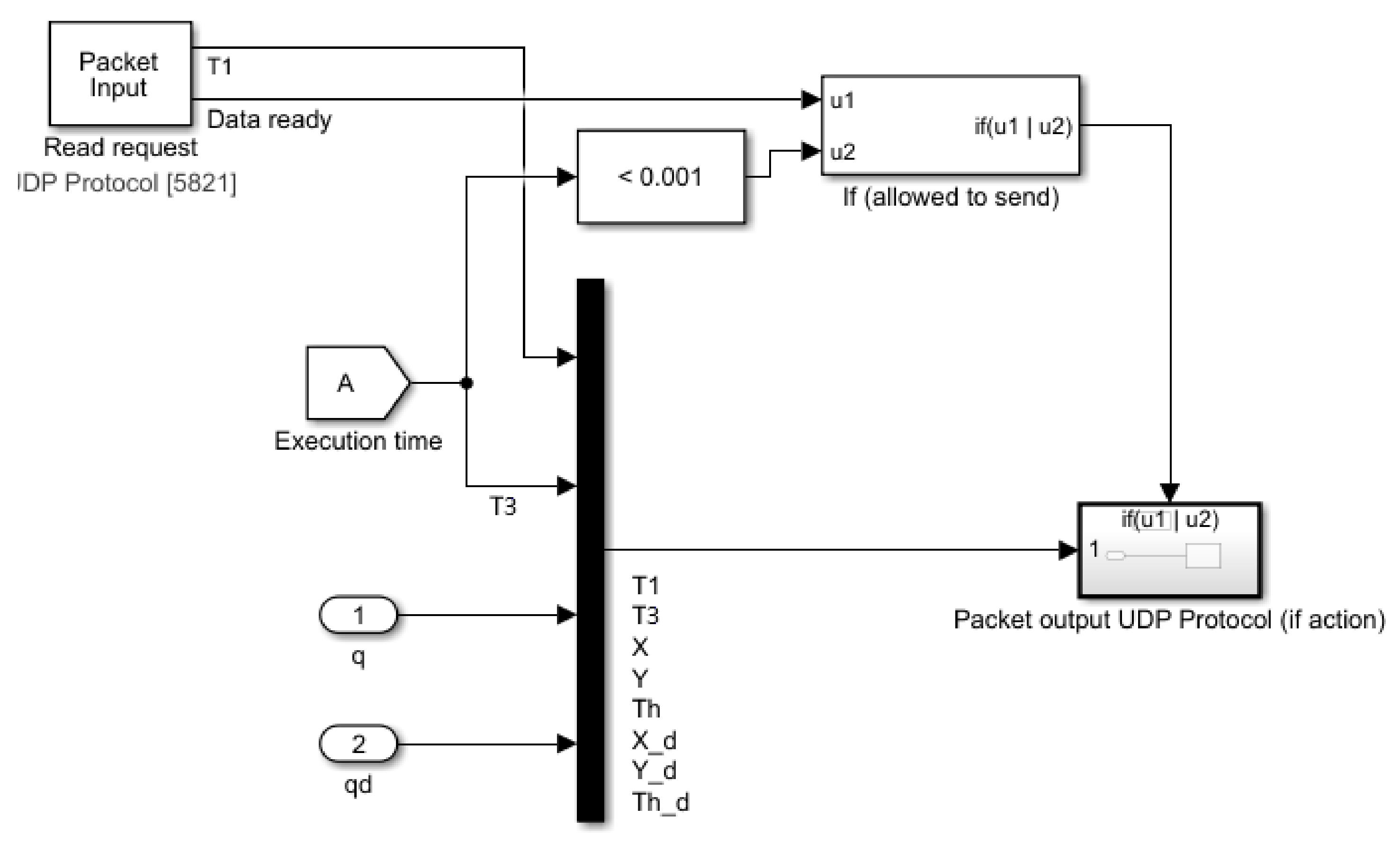
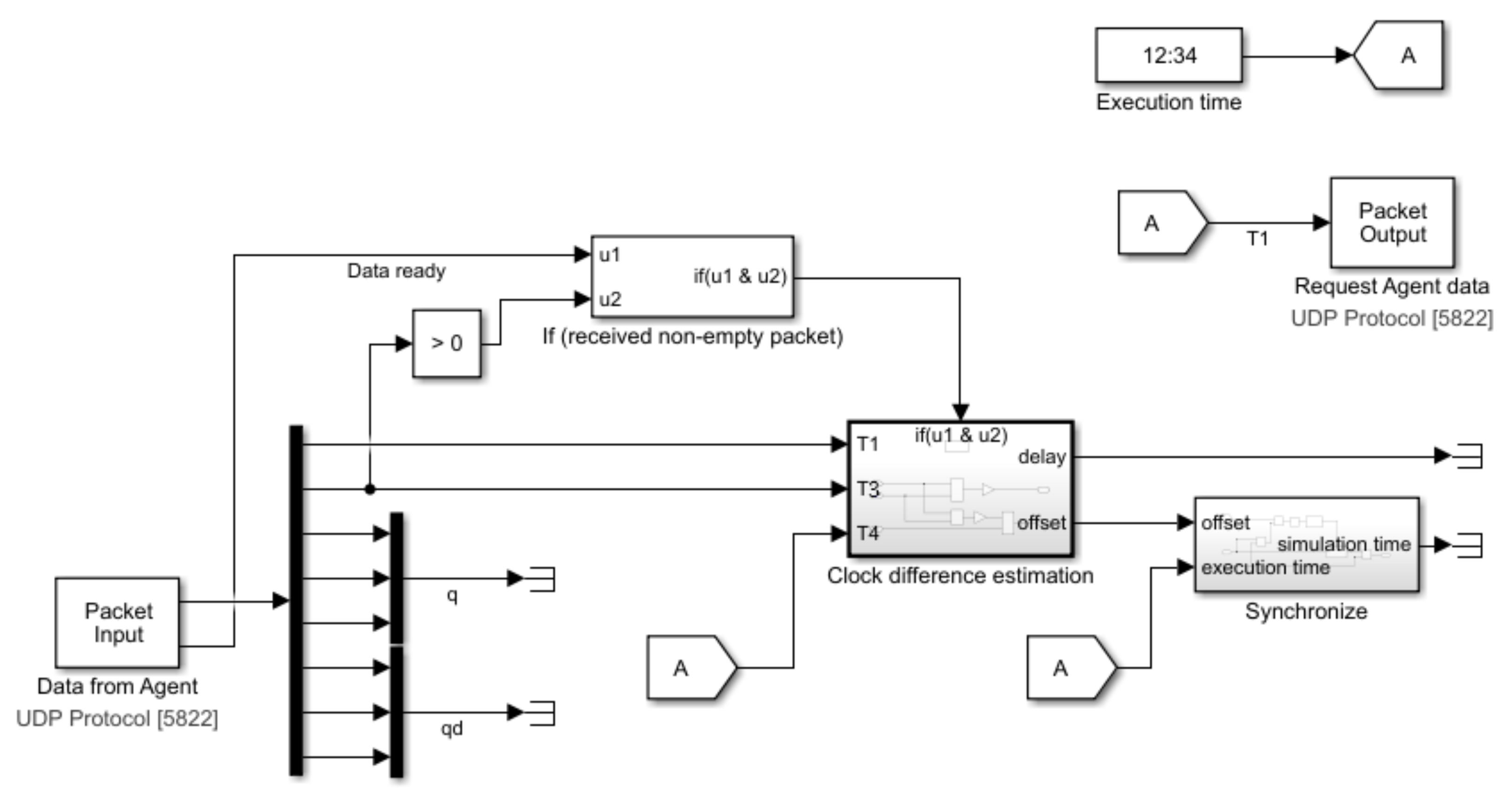
The purpose of the server is limited to forwarding the data to the client as soon as possible with no processing at all. The entire effort of estimating the time variables and of synchronizing its internal clock to the agreed simulation time is carried out by the client as shown in
Figure 7.
The current experiment setup was prepared to perform operations in which both platforms know their pose with respect to an inertial reference. This is the case, for example, of two satellites equipped with GNSS (Global Navigation Satellite System) receivers and star trackers that must coordinate their positions at two distant points. Relative measurements, on the other hand, are more adequate for proximity operations, such as docking. In order to mimic this scenario with the current protocol, the relative pose may be calculated by the simulation computers as the difference of the inertial measurements, adding a noise modeled to be consistent with the simulated sensor used for close proximity operations.
4. Validation of the Coordination Protocol
A series of simulations involving the virtual operation of KNATTE and PINOCCHIO were executed to validate the synchronization protocol and evaluate the stability of the network. During a session of experiments the operators of both laboratories kept a videoconferencing channel open to coordinate the execution of the simulations, report observations and troubleshoot any possible problems that may have occurred during the simulations. In such simulations, none of the platforms operated in frictionless mode. Instead, they remained stationary and shared a fictitious trajectory to their counterpart to make the appearance that they are actually moving.
During the execution of one experiment, both agents send requests messages to the reciprocal agent at regular intervals of 100 ms. This is the request time of the client (). In parallel, each agent checks both input UDP ports for packets every 1 ms and replies as fast as possible to the other agent while performing its primary mission tasks. In other words, the input period of the server () and the input period of the client () are equal to 1 ms. The server replies back as a reaction to an incoming request. Hence, the output period of the server () has not been explicitly configured but depends on . This is to avoid any chance of sending unnecessary empty packets.
Otherwise, if
is configured so that an agent sends unrequested packets at a regular interval the computational load of the required operations increase significantly. In that case, if
is less than 3 ms, we observed that there appeared conflicts with the received packets. If the request time (
) is too small, it also creates conflicts because the computer should dedicate most of its processing power to do diverse tasks. The other sampling times (
,
and
) cannot be too large and comparable to the one-way delay either, or that would cause significant errors in the estimation of such a delay. In general, the values of the sampling times may vary, but they must follow the rule in Equation (
7) to avoid problems.
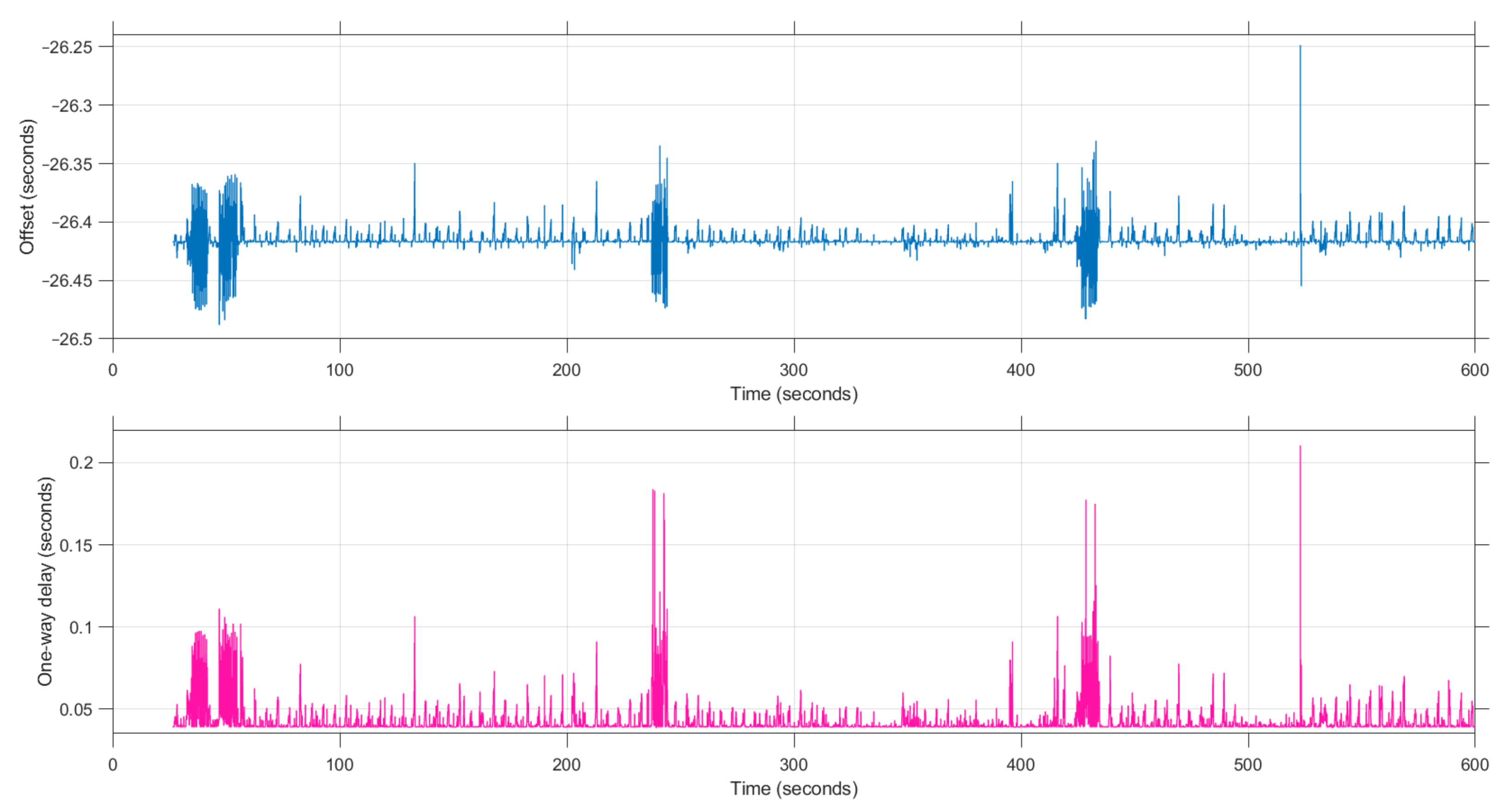
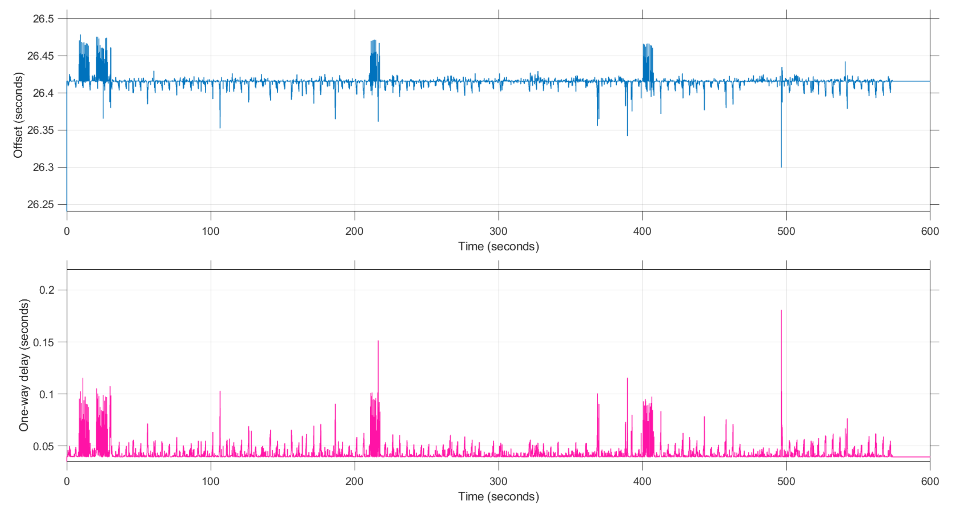
The results of performing a virtual coordination simulation during 600 s are given in
Figure 8 and
Figure 9.
Figure 8 shows the clock offset and one-way time delay for KNATTE, while
Figure 9 shows the same variables for PINOCCHIO. The most immediate observation is the fact that there is a consistent displacement of the plots for KNATTE with respect to the plots for PINOCCHIO. The reason being that KNATTE started the execution of its simulation earlier than PINOCCHIO; hence, no values could be estimated until PINOCCHIO started the simulation. This is also easy to detect by observing the different offset estimated by each agent. The median magnitude of the offset is identical in both cases and equal to 26.420 s with a standard deviation of 0.009 s for KNATTE and 0.005 s for PINOCCHIO. However, the offset measured by KNATTE is negative for the same reason.
Estimating the clock offset by measuring the time at which the second agent sends the first request may appear simpler, but still requires some coordination, is less reliable, is not symmetrical, is not scalable and depends on more uncontrollable factors at the moment of effectuating the measurement than following the proposed protocol.
Furthermore, the estimation of the delay is almost identical for both platforms in statistical terms, with 0.0395 s as the median delay found by KNATTE with a standard deviation of 0.011 s and 0.040 s the delay found by PINOCCHIO with a standard deviation of 0.005 s. Fluctuations happen simultaneously in the estimation of the delay and the offset. This is expected because both variables are calculated from the same set of measured time tags (, and ).
The uncertainty of the estimations may be related to differences in clock frequencies, the routes that each data packet follows through the network, the processing time at every network node, etc. Variations of the offset may deviate on both sides of the average because it is a measure of the round trip of the information and the conditions may change on both the outbound trip and the inbound. However, there is a physical limit on how fast data travels through the internet; hence, the lower limit of the one-way delay. Assuming a distance of 3900 km between our laboratories, the time of travel at the speed of light would be 0.013 s.
On top of that, the time to process and reroute the data packets between the servers on the way has to be added. That said, the plots also show some periods of several seconds with higher deviation in the offset and delay estimations. These periods seem to happen at regular intervals of approximately 3 min. Additionally, these events do not happen while working locally, leading us to conclude that the origin of these phenomena might be related to the multiple data transportation mechanisms that data packets experience on the way to the other laboratory and are out of our control. However, further investigations may be worthwhile.
5. Concurrent Experiment of Coordinated Operations
The complete coordination protocol was tested again, however, this time with both platforms performing physical maneuvers collectively. The logistics of such experiments are identical to those of
Section 4 with the additional hassle of preparing the initial setup and keeping the tank and battery operational.
The experiments that we performed assumed that one platform would act as a leader performing a trajectory and the other as a follower replicating such a trajectory. For that, we arbitrarily chose KNATTE to perform the role of the leader agent and PINOCCHIO the role of the follower agent.
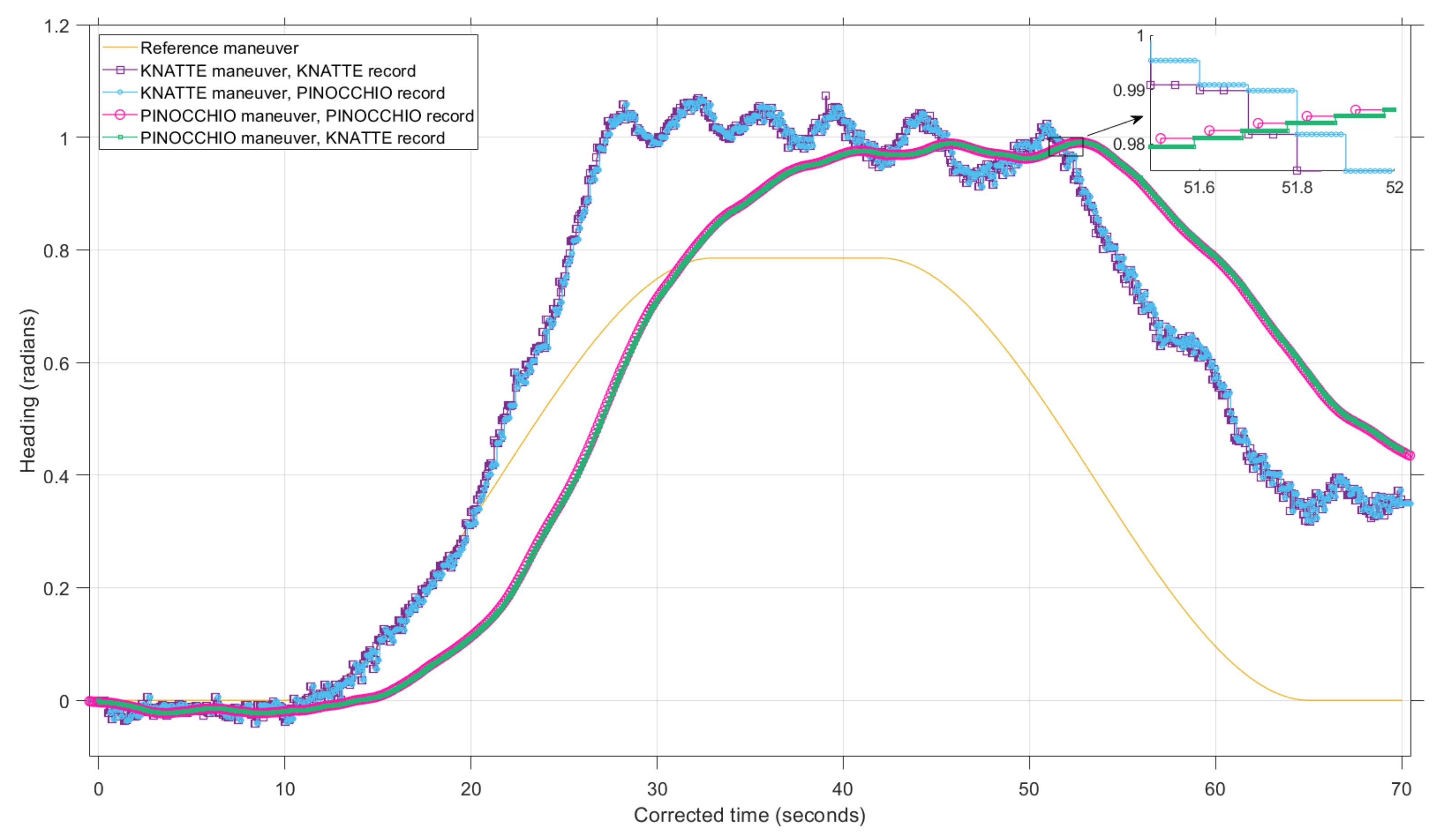
One experiment started with 10 s of inactivity to allow both platforms to perform the initial synchronization. After the first 10 s, KNATTE was commanded to make a reorientation maneuver consisting in a gradual rotation of 45 and come back to the original position in a span of 60 s. Meanwhile, the PINOCCHIO platform replicated the actual trajectory that KNATTE took based on the tracking data that was shared through the coordination protocol. For simplicity, the position of the platforms was not controlled, so the only goal was attitude synchronization.
Figure 10 shows the results for one run of coordinated operations. Other runs had similar results, and the discussion would be analogous. The KNATTE platform was instructed to follow the reference maneuver. However, such a platform failed to do so after 20 s from the beginning of the experiment due to distortions on the working surface and sub-optimal configuration of the controller gains.
That said, deviations from the reference are useful in this case to corroborate that PINOCCHIO was indeed following the command from KNATTE. Additionally, we can also compare the performance of both platforms. For that, the time reference in the plot was corrected to compensate the offset between the execution times of both platforms. In this specific case, the mean measured clock offset was 30.880 s with a standard deviation of 0.003 s. The performance of the PINOCCHIO platform can be measured by comparing the maneuver of PINOCCHIO with the maneuver of KNATTE as it is received by PINOCCHIO. To keep the experiment unbiased, PINOCCHIO is unaware of the maneuver that KNATTE should follow, relying solely on real-time data.
It can be seen that the controller gain settings of PINOCCHIO, a simple proportional-integral-derivative algorithm in this case, does not allow for a fast reaction to the variations in the attitude of KNATTE. This leads to a constant delay in the attitude of PINOCCHIO of about 4 to 5 s with respect to that of KNATTE. This delay is not caused by the synchronization or time offset issues, but rather a control performance issue. It must be noted that the main goal here is not to demonstrate a perfect tracking algorithm, but the possibility to perform experiments involving two platforms by connecting test facilities at different locations of the globe.
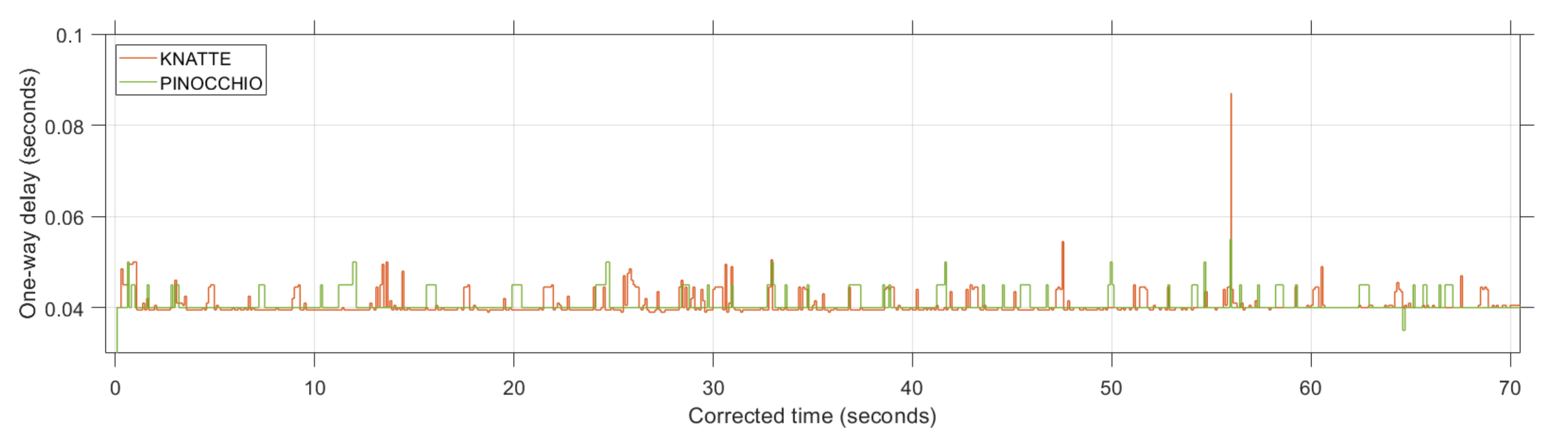
Figure 11 shows the variation of the measured delay for both platforms during the experiment. The results indicate that the protocol and the network behaved similarly to the simulations performed for protocol validation. In this case, KNATTE had measured a delay of 0.040 s with a standard deviation of 0.002 s, and PINOCCHIO measured the same delay with a standard deviation of 0.015 s. The difference in accuracy is due to a slower sampling rate for PINOCCHIO. As a conclusion, the implementation of the synchronization protocol with three time tags appears to be robust to the increase in computational power for the hardware experiments.
Even after correcting the offset from the execution time, the received heading curves appear consistently delayed compared to the sent ones. The approximate separation of the curves for the maneuver followed by KNATTE is 0.10 s, while the separation for the PINOCCHIO maneuver curves is 0.06 s. Such differences are justified partly by the oscillations of network delays. However, other effects are confounded in such margins since the maximum deviation for the one-way delay is 0.047 s. These additional effects may be justified by the different sampling rates and variations in the processing load. All in all, the effect of the communication delay is minimal considering the sent and received curves for both trajectories after clock correction.
6. Conclusions
One approach for conducting guidance, navigation and control experiments of coordinated operations was presented in this paper. We found a method in which the long distance that separates both platforms (∼3900 km) did not affect the experiment results.
For that, a synchronization protocol was developed as an adaptation and simplification of the well established Simple Network Time Protocol (SNTP). The proposed protocol, which used three time tags instead of the four time tags used in the SNTP, was demonstrated to be fast and accurate to estimate the clock offset and the communication delays between the platforms for the experiments that were carried on. That said, the use of a synchronization protocol with four time tags may be useful if the processing load required by any of the platforms increases to a value comparable to the delay, and the assumption of instantaneous reply is no longer applicable.
The approach presented in this paper was validated with virtual simulations of coordinated operations. Additionally, hardware-in-the-loop simulations with both frictionless platforms operating at remote facilities confirmed the result. The focus of the experiments was always on the performance of the coordination protocol focusing on the effects of the communications and processing of the telemetry data. The performance of the control algorithms was not evaluated in any of the experiments. We can obtain a more or less responsive behavior by selecting a different set of control gains for any of the platforms.
That said, the current arrangement allows for measuring and comparing the performance between the platforms by creating a common reference scenario. In fact, an additional feature of the approach is the promotion of concurrent engineering. With this approach, two or more teams can work with independent facilities and test the performance with a joint experiment. Those facilities can be very different in nature, e.g., virtual simulations, frictionless platforms, robot manipulators etc. The approach effectively liberates both groups of developers from being present at the same place in order to conduct their activities; however, they can still test their progress in a common setup.
In the future, the current set of scenarios may be improved by introducing more degrees of freedom to the facilities. However, the three degrees of freedom of the current platforms still allows for plenty research opportunities. For instance, more platforms could be added to the experiments in order to observe how the proposed protocol scales up. Another proposal is changing the experiment scenario to one in which the agents need to make decisions based on the shared information rather than follow a predetermined command.
Following this line, future developments may include adaptive control algorithms in which the platforms change the trajectory based on additional parameters. For example, the chaser platform could autonomously estimate the dynamic range of the leader trajectory, and change the control gains accordingly. Finally, we also consider modifications in the current synchronization algorithm. The fluctuations that are currently observed in the estimated offset might be compensated by adjusting the ticking frequency of the clocks.


 ,
, 


