Article

Non-Symmetric Gyroscope Skewed Pyramids

1
Department of Mechanical and Aerospace Engineering, Naval Postgraduate School, Monterey, CA 93943, USA
2
Department of Mechanical Engineering (CVN), Columbia University, New York, NY 10027, USA
*
Author to whom correspondence should be addressed.
These authors contributed equally to this work.
Aerospace 2019, 6(9), 98; https://doi.org/10.3390/aerospace6090098
Submission received: 8 July 2019 / Revised: 20 August 2019 / Accepted: 29 August 2019 / Published: 4 September 2019
(This article belongs to the Special Issue Spacecraft Attitude Determination and Control)

Abstract

:
The novel contribution in this manuscript is an expansion of the current state-of-the-art in the geometric installation of control moment gyroscopes beyond the benchmark symmetric skewed arrays and the four asymmetric arrays presented in recent literature. The benchmark pyramid symmetrically skewed at 54.73 degrees mandates significant attention to singularity avoidance, escape, and penetration, while the most recent four asymmetric arrays are strictly useful in instances where space is available to mount at least one gyro orthogonal to the others. Skewed arrays of gyros and the research-benchmark are introduced, followed by the present-day box-90 and “roof” configurations, where the roof configuration is the first prevalently used asymmetric geometry. Six other asymmetric options in the most recent literature are introduced, where four of the six options are obviously quite useful. From this inspiration, several dozen discrete options for asymmetric installations are critically evaluated using two figures of merit: maximum momentum (saturation) and maximum singularity-free momentum. Furthermore, continuous surface plots are presented to provide readers with countless (infinite) options for geometric installations. The manuscript firmly establishes many useful options for engineers who learn that the physical space on their spacecraft is insufficient to permit standard installations.

1. Introduction

Motion mechanics is governed by Euler’s moment equations for three degrees of rotation of rigid bodies in space [1], and Newton’s Law [2] for three dimensions of translation. External forces produce a change of linear momentum (i.e., a change in velocity with time for a constant mass), while external torques produce a change in angular momentum (i.e., a change in angular velocity with time for a constant mass moment of inertia). Rigid body motion mechanics governing spacecraft attitude control has a long, distinguished lineage of literature [3,4,5,6,7,8,9,10,11,12,13,14,15,16,17] that has culminated in recent advances using the governing Euler’s moment equations as the control [18,19,20,21,22,23,24,25,26,27] in a scheme called deterministic artificial intelligence [28,29]. One alternative to generating an external torque is to modify the angular momentum of some part(s) of the spacecraft, imparting motion for the entire system whilst maintaining conservation of the angular momentum. Control moment gyroscopes [30] are an example of such a system. Gyros use a relationship called a steering law [31,32,33,34,35,36] to calculate gyro commands for designed changes in angular momentum (torque commands generated by attitude controllers to accomplish a desired maneuver). Engineers design maneuvers in such a manner so that they never demand torque that would produce an angular momentum trajectory that is required to pass through a singular condition [37,38,39,40,41,42,43,44,45,46,47]. One of the methods used by engineers is to analyze and implement gyro installation at angles that yield the most usable momentum space [48], where usability is defined as singularity-free operations yielding the maximum angular momentum.
This manuscript introduces the control moment gyroscope as a spacecraft torque actuator in the benchmark installation geometry (symmetric arrays of gyros) modified to a non-redundant instantiation. The initial research on non-symmetric skewed arrays is briefly reviewed to illustrate the usefulness of the concept, since the introduction of asymmetry rotates the momentum space, allowing increased singularity-free torque production in a desired direction. Ubiquitous skew angle optimization for singularity-free operations results in symmetric arrays of gyros skewed at ninety degrees. From this baseline, depressing individual gyros from ninety to zero degree skew angles has already demonstrated momentum space rotation in the literature [43]. These 3n = 32 = 9 instantiations are the state-of-the-art for asymmetric skewed arrays. From this inspiration, this manuscript investigates many of the infinite possibilities for skew angle combinations. The figures of merit for comparison are the maximum singularity-free momentum and maximum (saturation) momentum capabilities. The originally sought research objective was to increase the yaw maneuvering capability, and several iterations towards this goal are presented.
In light of recent research illustrating the peculiarities of near-planar momentum associated with low skew angles [48], where two gyros are held in-plane at a zero (and near-zero) degree skew angle, while the third gyro is iterated. Subsequently, only one gyro is held at a very low (non-zero) skew angle, while iterating the other two. Pseudo-cardinal quantities (from a sinusoidal perspective) are also investigated by iterating each gyro through a zero, thirty, sixty, and ninety degrees skew angle. Other instantiations investigated include fifteen, twenty, thirty, forty, forty-five, sixty, eighty, and ninety.
Taken together, the manuscript comprises a novel initial articulation of asymmetric skewed arrays permitting guidance, navigation, and control engineers to participate in an integrated product team where other constituent members may enforce physical space constraints that preclude using the new-benchmark “box-90” configurations of symmetric gyros skewed at ninety degrees.

2. Materials and Methods

This study will be limited to non-redundant, constant-speed, single-gimbaled control moment gyroscopes (CMGs). Well-established methods are described first to elaborate typical skewed arrays of gyros (ubiquitous “benchmark” geometry [42]), inverse steering laws, and the gyro system matrix (referred to as [A] in the literature). The matrix contains time-varying gimbal angles that may be commanded to produce a desired torque, and the matrix also contains skew angles representing the gyro installation angle relative to the spacecraft reference frame. Changing these skew angles can bring about unique attributes for the spacecraft, such as an increased pitch, roll, or yaw capability. Mapping out these singularities for iterated gyro mounting geometries can show an engineer how to maximize these capabilities and enhance a spacecraft’s mission completion ability.

2.1. Benchmark Redundant Arrays and Non-Redundant Arrays

Figure 1b depicts a rigid spacecraft with four gyros (Figure 1a) described in [43], in the so-called benchmark configuration [42], where redundancy is from four gyros for three degrees of freedom embodied in three-dimensional motion. The spacecraft’s body reference frame is labeled x, y, and z, and each gyro is mounted at a fixed skew angle of β i i = 1 , 2 , 3 , 4 = β during installation.

2.2. State-of-the-Art Non-Redundant Symmetric Skewed Arrays

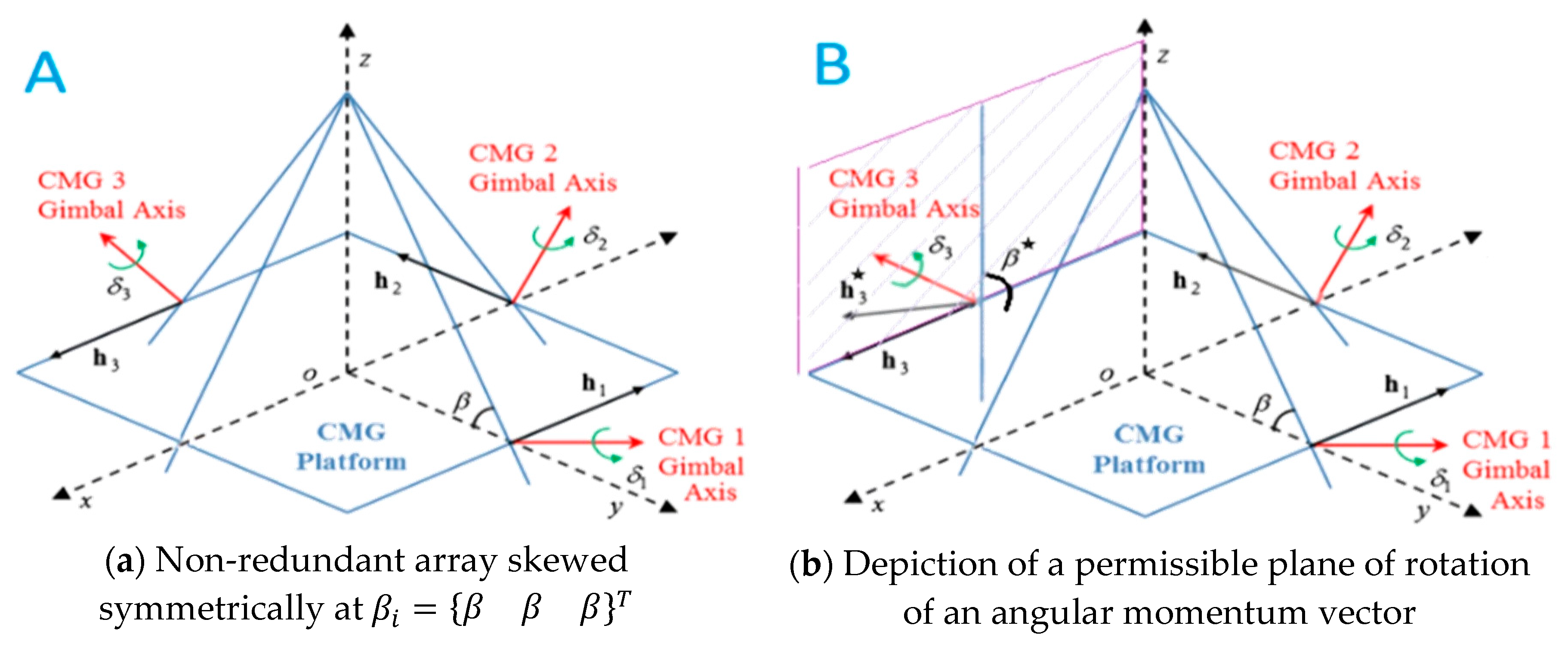
Typical non-redundant symmetric installation is depicted in Figure 2a, while recently developed asymmetric installation is depicted in 
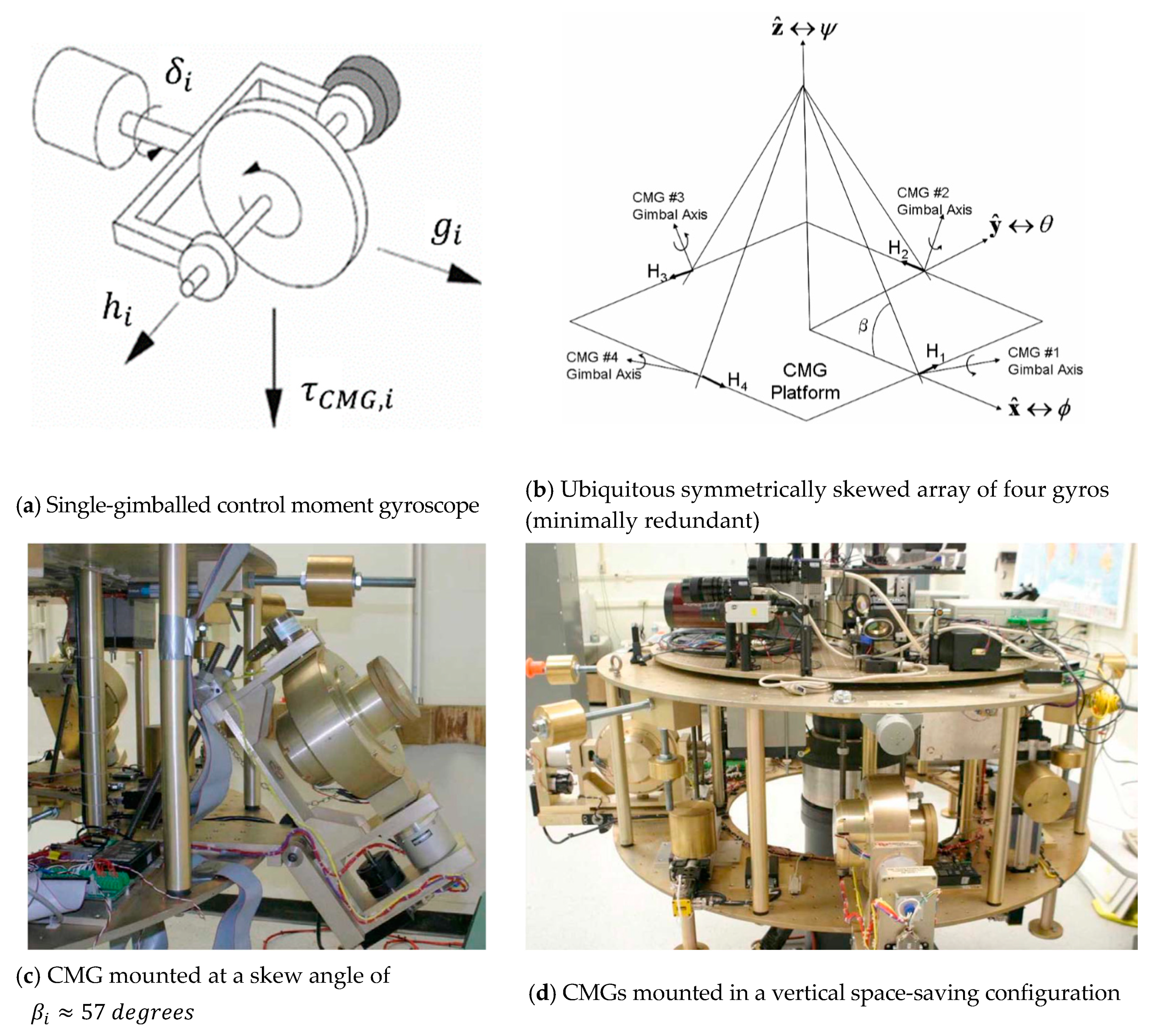
Figure 2b. Skew angles are not normally modified after installation. The gyros are gimballed, and their gimbal rotations about their respective gimbal axes are expressed as δ i i = 1 , 2 , 3 . Gimballing rotates the angular momentum vectors h i i = 1 , 2 , 3 in planes perpendicular to the gimbal axis, and these planes contain the respective torque vectors in a right-hand arrangement: angular momentum, torque, and the gimbal axis. The torque axis (τ) rotation for a CMG is the axis around which the spacecraft maneuver is accomplished. The torque axis and the orthogonal relationship between the CMG’s gimbal axis (δ) and angular momentum axis ( h i ) can be seen in Figure 1. These relationships demonstrate how one may discover the torque axis and provide the intuition behind singularity generation in this configuration [48].
Figure 2 depicts a rigid spacecraft with only three gyros (non-redundancy for three degrees of freedom embodied in three-dimensional motion) [44]. Frames and axes are consistently labeled with regards to the minimally redundant case in Figure 1, despite lacking a fourth gyro (the non-redundant case). Notice the literature’s [43,44] use of a capitalized H i to denote an individual gyro’s angular momentum (seen in Figure 1), while we prefer the use of a lower-case term assembled in the capitalized vector (seen in Figure 2) H = { h 1 h 2 h 3 } . Notice that vectors annotated in bold font in the figures are also written in equations using { } brackets, underlined terms, or even over-arrows.
According to Euler’s equation T i n e r t i a l = H ˙ i n e r t i a l = H ˙ B + ω B × H B , a time-derivative (rate of change) of the angular momentum is torque, here referred to as the (negative) torque of the CMGs, where τ C M G is referred to in typical literature on controls as the variable u . Equation (1) is the steering law (in the forward direction) that is merely the time-derivative of the projection of the individual angular momentum vector H = { h 1 h 2 h 3 } T . The relationship is expanded using the product rule for derivatives to express the change in angular momentum as the product of the gimbal rates and a spatial gradient Jacobian matrix containing gimbal angles and skew angles referred to in the literature as [ A ] . (ASIDE: notice the change in nomenclature from Figure 1, the benchmark configuration, where a lower-case hi is assembled into an upper-case vector H). The relationship must be inverted, since the control u is known, and the current known gimbal positions define the [ A ] matrix, while the necessary gimbal commands δ ˙ are unknown. Equation (2) reveals the inverse relationship for the gimbal steering commands, where control u is generated by typical equations of automatic control (e.g., a feedforward controller like nonlinear optimal control, and feedback controllers like PI-Proportional, Integral, PD-Proportional, Derivative, and PID-Proportional, Integral, Derivative controllers, etc.). The matrix inverse in Equation (2) is usually a matrix pseudoinverse in the literature, since the benchmark research configuration has four gyros providing four degrees of freedom for only three dimensions of motion (i.e., an overdetermined problem for which the pseudo-inverse is appropriate). The regular matrix inverse is correctly used here for this precisely determined problem where three degrees of freedom are used to provide three-dimensional motion. The [A] matrix is the spatial gradient matrix of angular momentum normalized by one gyro’s value of angular momentum, as per Equations (3) and (4).
τ C M G u = H ˙ = d H d t = d H d δ d δ d t [ A ] δ ˙
δ ˙ = [ A ] 1 u
H = { h x h y h z } = { c o s δ 3 c o s δ 1 + c o s β s i n δ 2 c o s β ( s i n δ 3 s i n δ 1 ) c o s δ 2 c o s β ( s i n δ 1 + s i n δ 2 + s i n δ 3 ) }
[ A ] = d H d δ = [ s i n δ 1 c o s β c o s δ 2 s i n δ 3 c o s β c o s δ 1 s i n δ 2 c o s β c o s δ 3 s i n β c o s δ 1 s i n β c o s δ 2 s i n β c o s δ 3 ]
It should be noted that the skew angles β i i = 1 , 2 , 3 = β are also in the [A] matrix in Equation (4) due to its use of projecting the angular momentum vectors of the gyros onto the spacecraft reference frame, as done in Equation (3). Therefore, β contributes to mathematical singularity, since the [A] must be inverted in Equation (2). The inverse itself is of interest in this study, and several methods of computing the inverse were investigated in this research for a non-redundant (three gyro) array, and the results are summarized in Table 1. While an analytic inverse is rarely used for overdetermined systems in favor of the pseudoinverse, since the steering matrix has a [3 × 3] dimension in this non-redundant case, analytical expressions are available in both matrix form and as decoupled, multiple equations. These are respectively named “analytic inverse” and “analytic formulas” in Table 1.
A common controversial issue is that the chosen computational implementations produce disparate results, despite using the same equation. One such computational implementation is the methodology chosen to calculate the matrix inverse (the source of mathematical singularities) in the steering law in Equation (2). In order to aid reproducibility of the results in this manuscript, seven common inversion methods are compared in Table 1, while the Moore–Penrose pseudoinverse was chosen here and implemented by the MATLAB pinv command. The Moore–Penrose pseudoinverse implemented in MATLAB was the baseline for comparison, since it had the lowest matrix norm error.

2.3. Benchmark Geometry: Optimal Symmetric Skew Angle

The minimally redundant (4-gyro skewed pyramid) has been extensively studied in the literature, with the consensus that the skew angle β i i = 1 , 2 , 3 , 4 = β = 54.73 degrees [42] establishes a spherical momentum envelope (maximal obtainable angular momentum). This skew angle is the benchmark from which subsequent research has grown in the past few decades, including the re-optimization of the skew angle [45] for the non-redundant to be introduced in the next section of this manuscript. The basis for the original benchmark optimization was to optimize the spherical nature of the outer momentum generation capability (i.e., saturation). Additional knowledge on this aspect of the benchmark geometry is revealed later in this manuscript, when the asymmetric geometries are evaluated for the first time for a maximal (saturation) performance.

2.4. State-of-the-Art Geometry: Re-Optimized Symmetric Skew Angle

The current state-of-the-art for gyro-pyramid installation geometry comes from a re-optimization of spherical singularity-free angular momentum, and is often referred to in industry as the slang term “box-90”. Notice the substantial difference between the displays in Figure 3 and Figure 4 of the pyramid singularity hypersurfaces. This heuristically illustrates the benefit of the bi-planar generation of angular momentum, while [48] reveals some weaknesses with the counter-opposing philosophy, near co-planar angular momentum generation. Another configuration that has recently arisen to be commonplace in industry is a “roof configuration”, which will now be elaborated.

2.5. State-of-the-Art Asymmetric Geometry: Iterated Non-Symmetric Orthogonal Skew Angles

The depiction of angular momentum planes established by the use of “mixed” skew angles results in asymmetries, while the slang “roof configuration” is obviously applicable when the plane for gyro #2 rotates from 90 degrees to 0 degrees (establishing a “roof/floor” on the seemingly walled-structure). While the box-90 configuration has a maximal capability around the y-axis (pitch), the investigation described in [43] consecutively analyzed installations where each gyro(s) is/are rotated from 90 degrees to 0 degrees. The result is rotation of the singularity hypersurfaces, where the “roof” configuration depresses gyro #2 from 90 to 0 degrees, and the maximal capability is established in the z-direction (yaw).
Six instances of non-symmetric skewed pyramids are the current state-of-the-art, but only four options have immediately obvious benefits. The other four subplots are desirable installations for engineers who learn that their space missions need a predominant capability around the roll, pitch, or yaw, respectively, as listed in Table 2. This legacy research inspires new developments in this manuscript. What should an engineer do if they learn that their space mission requires predominant capabilities about some intermediate axis (e.g., an axis in the x-z plane)? What if (for example) a gyro’s mounting space gets prohibitively restricted?

2.6. Methodology

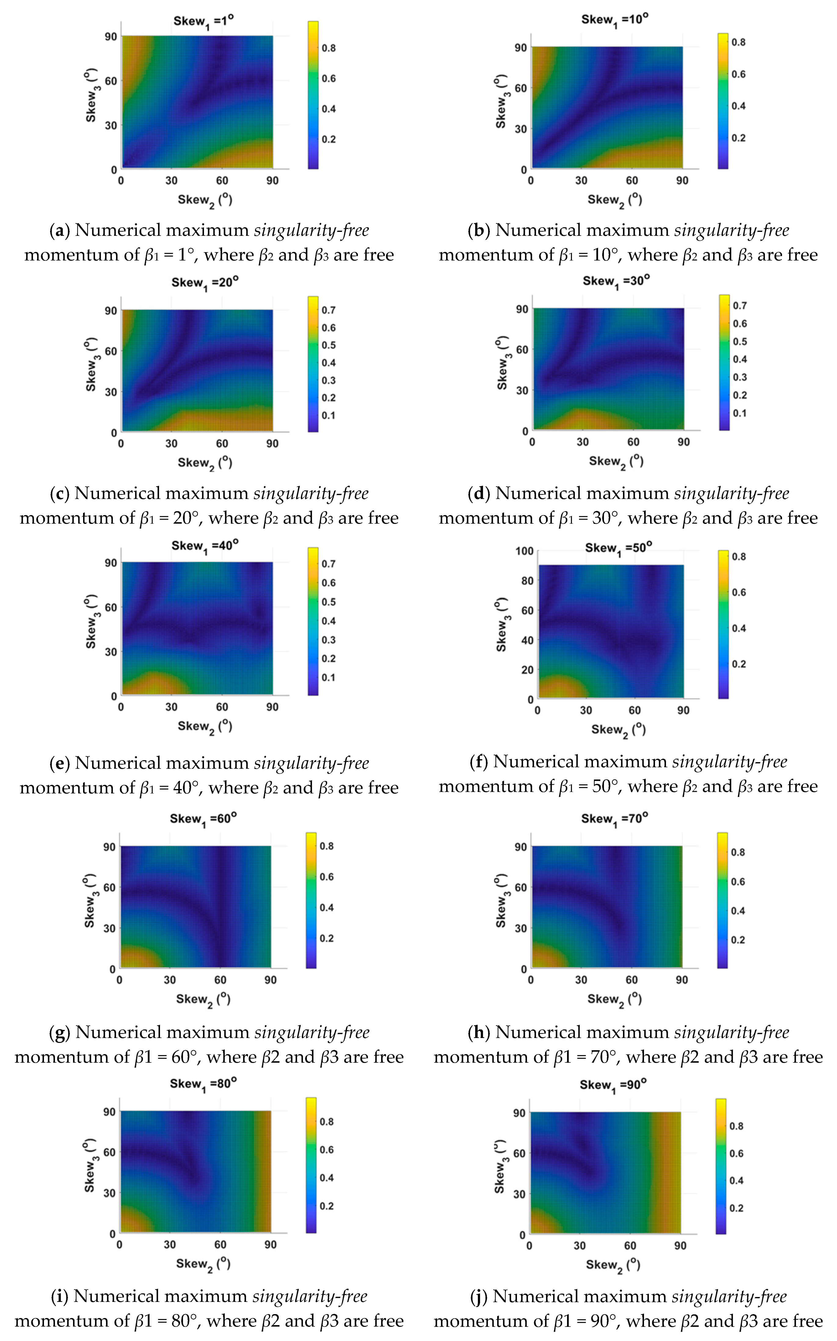
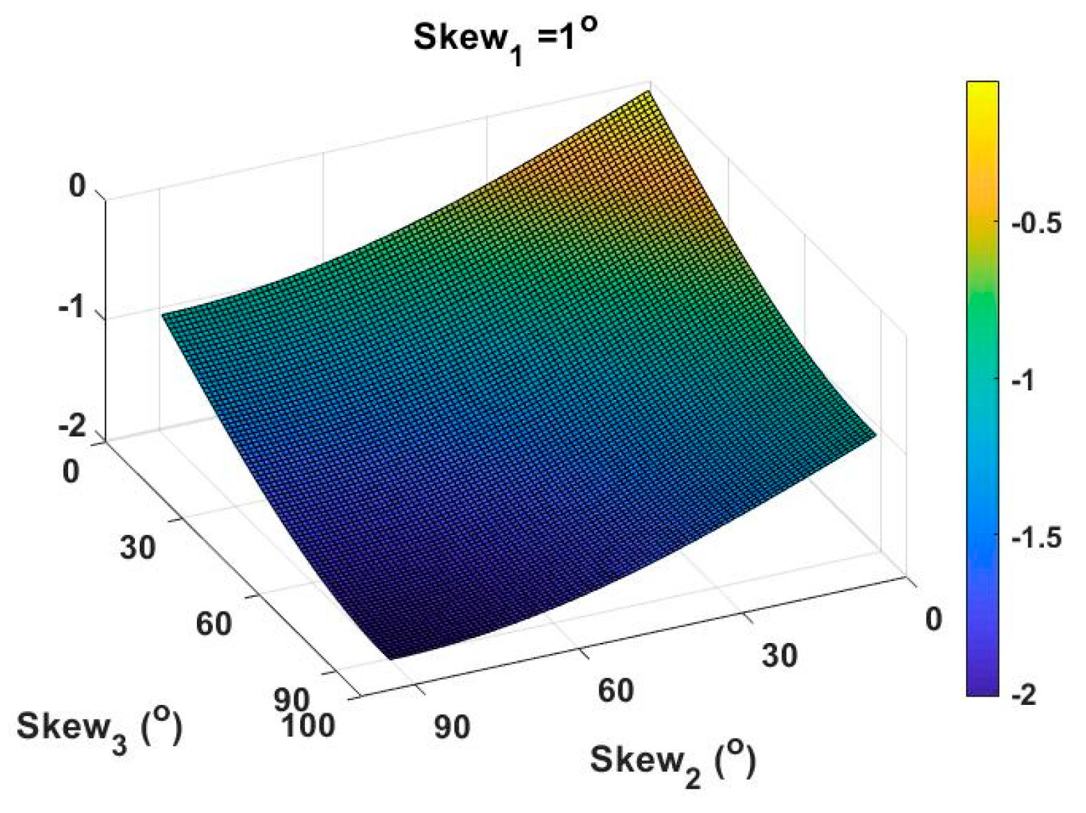
There does not exist a reference volume that includes many, a dozen, or continuous infinite selections of installation geometries (options for skew angles, β ), and Section 3 accomplishes this key novel contribution to the field. Towards the goal of creating such a reference volume, Section 3 of this manuscript reveals the results of our research starting from the current state-of-the-art summarized in 
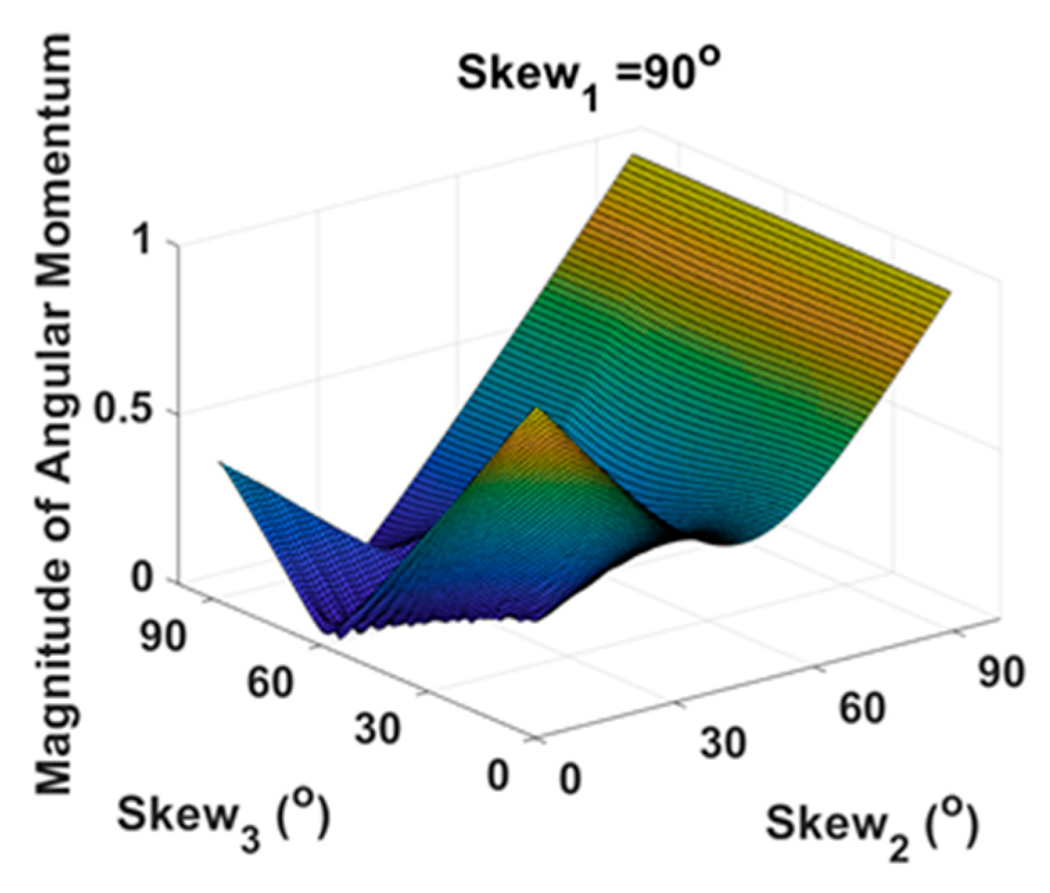
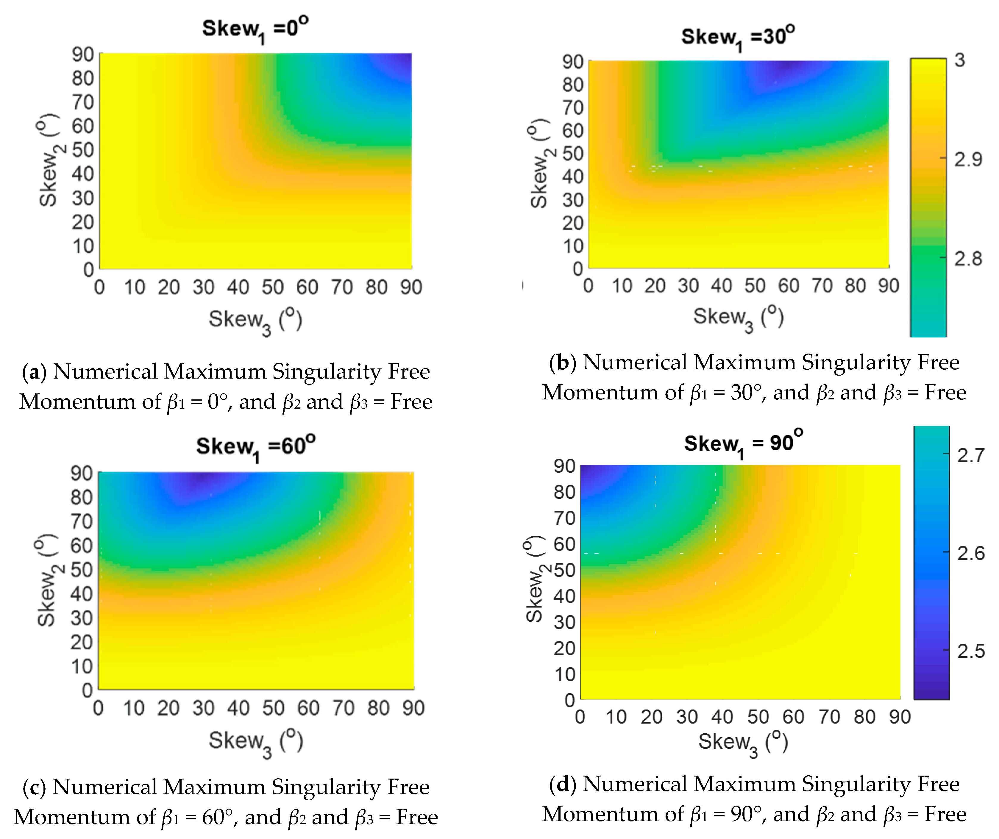
Table 2 that has already been presented in the literature. We commence with holding gyro #1 at a 90-degree skew angle and allowing gyros #2 and #3 to vary continuously from 0 to 90 degrees. Similarly, we examine holding gyro #1 at zero degrees and permitting the other two gyros to be installed at any arbitrary angle. Next, we step through logical iterations: what happens when two gyros are fixed and a third is free. Considering recent companion research [48] by the authors illustrating peculiarities of near-planar momentum generation associated with very low skew angles, and following the logical iteration methodology, we next consider holding two gyros at very low skew angles. The aforementioned iterations reveal the maximum singularity-free momentum space available (an inner momentum space), so lastly, we investigate the maximum (saturation) capability, regardless of inner singularities akin to the original benchmark optimization [42].

3. Results

We have introduced the benchmark geometry (Figure 1 and Figure 3) and its corollary state-of-the art non-redundant modification (Figure 2, Figure 4 and Figure 5), in addition to initial implementations of asymmetric arrays. The next section’s motivation is the fact that engineers may not always be permitted to install one or more gyro skewed at ninety degrees, occupying the most physical space of all options. Consider a gyro of an arbitrary dimension of unity. Symmetric mounting of three or four such gyros occupies one unit in the vertical plane and also one unit in the horizontal plane. Meanwhile, depressing either of the planes to non-orthogonal mounting at less than ninety degrees requires space of less than one unit. The spinning mass remains in the same dimension, as does the gimbal and mounting hardware, but we rotate that dimension away from an orthogonal plane, reducing the space occupied by the apparatus. Therefore, symmetric, orthogonal mounting at ninety degrees requires the most space onboard a spacecraft compared to any of the other options. Quickly peak back to Figure 1b and notice how depressing the skew angle reduces the height of the pyramid. Similarly, the long-axis of the CMG (depicted in Figure 1a) depresses, reducing the physical size requirement inside the spacecraft.
Space systems engineers might be required to install one of more gyros at an angle of less than ninety degrees to (for example) make physical space available to another subsystem (e.g., a cold gas thruster tank, propellant piping, heat exchangers, etc.).

Novel, Non-Symmetric, Non-Orthogonal Skew Angles

With the understanding that all references to angular momentum are normalized by one gyro’s angular momentum capability (i.e., so-called 1h, 2h, and 3h nomenclature ubiquitous in the literature), we commence the investigation by holding gyro #1 at a 90-degree skew angle and allowing gyros #2 and #3 to vary continuously from 0 to 90 degrees (depicted in Figure 3). The results are self-validating by examining the singularity-free maximum momentum capability for the symmetric case (since it is one of the infinite iterations). β i i = 1 , 2 , 3 = β = 90 degrees is illustrated in Figure 3 to produce 1h, which is one gyros worth of angular momentum, and this exactly coincides with the contemporary literature on the “box-90” configuration. Due to the difficulties in visualizing all the possible iterations of angles in Figure 3, we “flatten” the depictions to two-dimensions, necessitating multiple plots depicted in Figure 4 for four semi-cardinal values for the skew angle of gyro #1.
Inspired by the effectiveness of momentum space rotation of the “roof” configuration established by laying down the center gyro (gyro #2 here) to zero degrees, companion research by the authors [48] investigated issues that arise when using other combinations of low skew angles. Figure 5 is inspired by the companion research which claims peculiarities with low-skew angle combinations (albeit the “roof” configuration has proven quite effective). We take gyro #1 as the illustrative example, since it has a counterpart, gyro #3, which acts in a parallel plane. Immediately evident in Figure 5a is the fact that laying gyro #1 to a near-zero skew angle does not bestow a benefit unless one of the other gyros is also depressed (allowing near 1h capabilities). Notice how poorly the configuration performs if only gyro #1 is depressed, leaving the other two gyros at ninety degrees. As a matter of fact, the only favorable regions of Figure 5a are in the upper-left and lower-right corners, where one of the other respective gyros is also depressed to zero degrees. Another aspect evident in Figure 5 is the nature of the right hand side of each subplot. Notice that the far-right sides of the plots become only yellow (best performing) when skew angles all are beyond 60 degrees (precisely validating the discovery in the companion research that revealed peculiarities of near-planar momentum associate with low skew angles).
Figure 6 presents a three-dimensional version of Figure 5 (gyro #1 held at 1 degree) akin to Figure 4’s original presentation of gyro #1 held at ninety degrees. Meanwhile, Figure 6 moves away from singularity-free capability to focus on maximal (saturation) capability, but the iterations are similar: we iterate the skew angle of gyro #1 discretely, and present continuous (infinite) iterations of the other two skew angles. Table 3 contains the maximum yaw maneuverability skew angle combinations. The space mission motivating this research needed to maximize yaw maneuverability. While the analysis displayed in Figure 4, Figure 5 and Figure 6 provides (infinite) continuous optional alternatives for mounting gyros asymmetrically, the graphic depictions nonetheless can make it difficult to discern the exact capability of a discrete combination of asymmetric skew angles. To remedy this deficiency, the analyses of discrete options are listed in Table 4, Table 5, Table 6 and Table 7. For example, if a space mission dictates two that gyros must be set to a skew angle lower than ninety degrees, several discrete options are immediately evident, and some even maintain a very similar singularity-free momentum capability (e.g., β = { 80 1 1 } T yields 097h, while the box-90 configuration β = { 90 90 90 } T yields 1h).
Next, we iterated only gyro #1’s installed skew angle, retaining other skew angles at zero degrees. We investigated one-thousand iterations of mixed skew angles, and some key iterations are described here. Once again, the maximum amplitude is 1h, representing one gyro’s worth of angular momentum, but furthermore, there is an almost noticeable pattern in the results. Iterations 201, 301, 401, 501, 601, 701, and 801 all peak at 1h. The skew angle combinations responsible for these peaks can be seen in Table 4. These results indicate that having two gyro’s with a skew angle of zero results in high allowable angular momentum values. Space is at a premium on a spacecraft and this information could prove useful if a certain gyro configuration can be made to fit onboard.
Afterwards, we iterated both gyros #1 and 2 while holding gyro #3 at a very low value of one degree, and the results are provided in Table 5, followed by numerous further iterations in Table 6 and Table 7.

4. Discussion

Previously established in the 1990’s, control moment gyroscope installation geometry is ubiquitously accepted to include minimally redundant (four) gyros mounted at symmetric skew angles of 56.73 degrees to generate maximum spherical momentum at the outer saturation surface. This benchmark has necessitated considerably voluminous research into singularity avoidance, singularity escape (when avoidance fails), and singularity penetration. In the 2000’s, the benchmark was replaced by the “box-90” configuration prevalent in industry today, following a re-optimization of the symmetric skew angle to maximize the inner zone of singularity-free momentum space. Coincidently, initial asymmetric geometries were introduced without expansive explanatory research, and these geometries were demonstrated to provide useful options for singularity-free momentum generation capabilities in instances where gyros could not all be installed at ninety degrees.
With this auspicious beginning, this manuscript provides a more comprehensive treatment of asymmetric options for gyro installations by providing several dozen discrete options for skew angle combinations. Furthermore, surface plots are provided to allow readers to mentally iterate in between the discrete cases provided. This manuscript establishes a reference article to future systems. Future research will include experimental validation of these results on actual space hardware, either in-orbit or using free-floating spacecraft simulators in laboratories.
This study concludes that infinitely more useful asymmetric options are available than currently reflected in the predominant literature. No specific, single configuration is urged; rather, many optional configurations are identified as having identical performance characteristics, while occupying a reduced space. By “performance”, we mean both the maximum momentum capability and the maximum singularity-free momentum capability. For engineers utilizing control moment gyroscopes in space-constrained environments, we recommend using the results here to choose options that require less physical space onboard the vehicle than the ubiquitous symmetric array skewed at ninety degrees.

5. Patents

Patent 9,567,112 February 14, 2017 by the author illustrates methods of singularity avoidance without null motion and singularity penetration in the event that trajectories enter singularities [47].

Author Contributions

Conceptualization, T.S.; methodology, T.S.; software, T.S., J.L, K.B., J.T.E., Z.L., and E.C.; validation, T.S.; formal analysis, T.S., J.L, K.B., J.T.E., Z.L., and E.C.; investigation, T.S., J.L, K.B., J.T.E., Z.L., and E.C.; writing—original draft preparation, T.S.; writing—review and editing, T.S.; visualization, T.S., J.L, K.B., J.T.E., Z.L., and E.C.; funding acquisition, T.S.

Funding

This research received no external funding. The APC was funded by T.S.

Acknowledgments

No funds were received to support this research or for covering the costs to publish in open access. The authors give special thanks to Marcello Romano for permitting us to use his course while on sabbatical as the venue for this investigation. Timothy Sands is not a tenured faculty member of Columbia University; rather he is the Associate Dean of the Naval Postgraduate School’s Graduate School of Engineering and Applied Sciences. In order to avoid legal jeopardy, Timothy Sands publishes government-funded research under his association with the Naval Postgraduate School, while publishing non-government funded research under his continuing associations with Stanford and Columbia Universities.

Conflicts of Interest

The authors declare no conflicts of interest.

References

  1. Euler, L. (Euler) Formulae Generales pro Translatione Quacunque Corporum Rigidorum (General Formulas for the Translation of Arbitrary Rigid Bodies, Presented to St. Petersburg Academy on 9 October 1775. First Published in Novi Commentarii Academiae Scientiarum Petropolitanae 20, 1776, pp. 189–207 (E478) and Was Reprinted in Theoria Motus Corporum Rigidorum, ed. nova, 1790, pp. 449–460 (E478a) and Later in His Collected Works Opera Omnia, Series 2. Volume 9, pp. 84–98. Available online: https://math.dartmouth.edu/~euler/docs/originals/E478.pdf (accessed on 22 August 2018).
  2. Newtono, I. Philosophia Naturalis Principia Mathematica; Kessinger Publishing, LLC: Whitefish, MT, USA, 2008; ISBN 0548952612. [Google Scholar]
  3. Thompson, W.; Tait, P.G. Elements of Natural Philosophy; Cambridge University Press: Cambridge, UK, 1872. [Google Scholar]
  4. Reuleaux, F.; Kennedy Alex, B.W. The Kinematics of Machinery: Outlines of a Theory of Machines; Macmillan: London, UK, 1876; Available online: https://archive.org/details/kinematicsofmach00reuluoft (accessed on 22 August 2018).
  5. Wright, T.W. Elements of Mechanics Including Kinematics, Kinetics and Statics; D. Van Nostrand Company: New York, NY, USA, 1896. [Google Scholar]
  6. Merz, J.T. A History of European Thought in the Nineteenth Century; Blackwood: London, UK, 1903; p. 5. [Google Scholar]
  7. Whittaker, E.T. A Treatise on the Analytical Dynamics of Particles and Rigid Bodies; Cambridge University Press: New York, NY, USA, 1904. [Google Scholar]
  8. Whittaker, E.T. A Treatise on the Analytical Dynamics of Particles and Rigid Bodies; Cambridge University Press: New York, NY, USA, 1937. [Google Scholar]
  9. Church, I.P. Mechanics of Engineering; Wiley: New York, NY, USA, 1908. [Google Scholar]
  10. Wright, T.W. Elements of Mechanics Including Kinematics, Kinetics, and Statics, with Applications; Nostrand: New York, NY, USA, 1909. [Google Scholar]
  11. Study, E.; Delphenich, D.H. Foundations and goals of analytical kinematics. Sitzber. D. Berl. Math. Ges. 1913, 13, 36–60. Available online: http://neo-classical-physics.info/uploads/3/4/3/6/34363841/study-analytical_kinematics.pdf (accessed on 14 April 2017).
  12. Gray, A. A Treatise on Gyrostatics and Rotational Motion; MacMillan: London, UK, 1918; ISBN 978-1-4212-5592-7. [Google Scholar]
  13. Rose, M.E. Elementary Theory of Angular Momentum; John Wiley & Sons: New York, NY, USA, 1957; ISBN 978-0-486-68480-2. [Google Scholar]
  14. Kane, T.R. Analytical Elements of Mechanics Volume 1; Academic Press: Cambridge, MA, USA, 1959. [Google Scholar]
  15. Kane, T.R. Analytical Elements of Mechanics Volume 2 Dynamics; Academic Press: Cambridge, MA, USA, 1961. [Google Scholar]
  16. Thompson, W. Space Dynamics; Wiley and Sons: New York, NY, USA, 1961. [Google Scholar]
  17. Greenwood, D. Principles of Dynamics; Prentice-Hall: Englewood Cliffs, NJ, USA, 1965; ISBN 9780137089741. [Google Scholar]
  18. Sands, T.; Kim, J.J.; Agrawal, B.N. Spacecraft fine tracking pointing using adaptive control. In Proceedings of the 58th International Astronautical Congress, Hyderabad, India, 24–28 September 2007. [Google Scholar]
  19. Sands, T.; Kim, J.J.; Agrawal, B.N. Improved Hamiltonian adaptive control of spacecraft. In Proceedings of the IEEE Aerospace, Big Sky, MT, USA, 7–14 March 2009; IEEE Publishing: Piscataway, NJ, USA, 2009; pp. 1–10. [Google Scholar]
  20. Sands, T.; Kim, J.J.; Agrawal, B.N. Spacecraft Adaptive Control Evaluation. In Proceedings of the Infotech@ Aerospace, Garden Grove, CA, USA, 19–21 June 2012; American Institute of Aeronautics and Astronautics: Reston, VA, USA, 2012; pp. 2012–2476. [Google Scholar]
  21. Sands, T. Phase lag elimination at all frequencies for full state estimation of spacecraft attitude. Phys. J. 2017, 3, 1–12. [Google Scholar]
  22. Cooper, M.; Heidlauf, P.; Sands, T. Controlling chaos—Forced van der pol equation. Mathematics 2017, 5, 70. [Google Scholar] [CrossRef]
  23. Sands, T.; Kenny, T. Experimental piezoelectric system identification. J. Mech. Eng. Autom. 2017, 7, 179–195. [Google Scholar] [CrossRef]
  24. Sands, T. Space systems identification algorithms. J. Space Exp. 2017, 6, 138–149. [Google Scholar]
  25. Sands, T.; Kenny, T. Experimental sensor characterization. J. Space Exp. 2018, 7, 140. [Google Scholar]
  26. Sands, T.; Armani, C. Analysis, correlation, and estimation for control of material properties. J. Mech. Eng. Autom. 2018, 8, 7–31. [Google Scholar] [CrossRef]
  27. Smeresky, B.; Rizzo, A.; Sands, T. Kinematics in the Information Age. Math. Eng. 2018, 6, 148. [Google Scholar] [CrossRef]
  28. Sands, T. Predictive control design paradigm for optimality and robustness. Algorithms 2019. under review (invited submission). [Google Scholar]
  29. Sands, T. Whiplash Compensation for flexible space robotics. Aerospace 2019. accepted (invited submission). [Google Scholar]
  30. Branets, V.N.; Weinberg, D.M.; Verestchagin, V.P.; Danilov-Nitusov, N.N.; Legostayev, V.P.; Platonov, V.N.; Semyonov, Y.P.; Semyachkin, V.S.; Chertock, B.E.; Sheremetyevsky, N.N. Development Experience of the Attitude Control System Using Single-Axis Control Moment Gyros for Long-Term Orbiting Space Stations. In Proceedings of the 38th Congress of the lnternational Astronautical Federation, Brighton, UK, 10–17 October 1987. [Google Scholar]
  31. Bedrossian, N.S.; Paradiso, J.; Bergmann, E.V.; Rowell, D. Steering Law Design for Redundant Single-Gimbal Control Moment Gyroscopes. J. Guidance Control Dyn. 1990, 13, 1083–1089. [Google Scholar] [CrossRef]
  32. Bedrossian, N.S.; Paradiso, J.; Bergmann, E.V.; Rowell, D. Redundant Single-Gimbal Control Moment Gyroscope Singularity Analysis. J. Guidance Control Dyn. 1990, 13, 1096–1101. [Google Scholar] [CrossRef]
  33. Vadali, S.R.; Oh, H.; Walker, S. Preferred Gimbal Angles for Single Gimbal Control Moment Gyroscopes. J. Guidance Control Dyn. 1990, 13, 1090–1095. [Google Scholar] [CrossRef]
  34. Oh, H.-S.; Vadali, S.R. Feedback Control and Steering Laws for Spacecraft Using Single Gimbal Control Moment Gyroscopes. J. Guidance Control Dyn. 1991, 39, 183–203. [Google Scholar]
  35. Paradiso, J.A. Global Steering of Single Gimballed Control Moment Gyroscopes Using a Direct Search. J. Guidance Control Dyn. 1992, 15, 1236–1244. [Google Scholar] [CrossRef]
  36. Hoelscher, B.R.; Vadali, S.R. Optimal Open-Loop and Feedback Control Using Single Gimbal Control Moment Gyroscopes. J. Astronaut. Sci. 1994, 42, 189–206. [Google Scholar]
  37. Kurokawa, H. Exact Singularity Avoidance Control of the Pyramid Type CMG System. In Proceedings of the AIAA Guidance, Navigation, and Control Conference, AIAA, Washington, DC, USA, 3 August 1994; pp. 170–180. [Google Scholar]
  38. Vadali, S.R.; Krishnan, S. Suboptimal Command Generation for Control Moment Gyroscopes and Feedback Control of Spacecraft. J. Guidance Control Dyn. 1995, 18, 1350–1354. [Google Scholar] [CrossRef]
  39. Kurokawa, H. Constrained Steering Law of Pyramid-Type Control Moment Gyros and Ground Tests. J. Guidance Control Dyn 1997, 20, 445–449. [Google Scholar] [CrossRef]
  40. Heiberg, C.J.; Bailey, D.; Wie, B. Precision Pointing Control of Agile Spacecraft Using Single-Gimbal Control Moment Gyros. In Proceedings of the AIAA Guidance, Navigation, and Control Conference, AIAA, Washington, DC, USA, 13 August 1997; pp. 1620–1632. [Google Scholar]
  41. Paradiso, J. A Search-Based Approach to Steering Single-Gimbaled CMGs; Technical Report CSDL-R-2261; Draper Laboratory: Cambridge, MA, USA, 1991. [Google Scholar]
  42. Wie, B. Space Vehicle Dynamics and Control, 1st ed.; American Institute of Aeronautics & Astronautics: Reston, VA, USA, 1998. [Google Scholar]
  43. Sands, T. Fine Pointing of Military Spacecraft. Ph.D. Thesis, Naval Postgraduate School, Monterey, CA, USA, March 2007. [Google Scholar]
  44. Sands, T. Control Moment Gyroscope Singularity Reduction via Decoupled Control. In Proceedings of the IEEE SEC, Atlanta, GA, USA, 5–8 March 2009. [Google Scholar]
  45. Sands, T.; Kim, J.; Agrawal, B. Experiments in Control of Rotational Mechanics. Int. J. Autom. Control Int. Syst. 2016, 2, 9–22. [Google Scholar]
  46. Sands, T.; Lu, D.; Chu, J.; Cheng, B. Developments in angular momentum exchange. Intl. J. Aerosp. Sci. 2018, 6, 1–6. [Google Scholar] [CrossRef]
  47. Sands, T.; Kim, J.; Agrawal, B. Singularity Penetration with Unit Delay (SPUD). Mathematics on Automation Control Systems. Mathematics 2018, 6, 23. [Google Scholar] [CrossRef]
  48. Sands, T.; Baker, K.; Culton, E.; Ten Eych, J.; Lewis, Z. Peculiarities of near planar momentum generation. Aerospace 2019. under review. [Google Scholar]
Figure 1. Control moment gyroscopes (a) placed onto a spacecraft mounted at a skew angle, with β depicted here (b) in the former research benchmark with minimally redundant (four) gyros arranged in the shape of a pyramid skewed at the symmetric angle, β . Notice the reduced vertical space occupied by the gyros in (d) compared to the vertical space occupied by the gyro in (c). This vertical space reduction is one reason why engineers might need to understand configurations with one or more gyro mounted at disparate skew angles resulting in an asymmetric configuration.
Aerospace 06 00098 g001
Figure 2. Spacecraft body axes serving as basis vectors in schematic drawings of skewed SGCMG array geometries, noting the angular momentum, torque, and gimbal vectors that define a right-hand set.
Aerospace 06 00098 g002
Figure 3. Maximum Singularity Free Momentum of β1 = 90°, and β2, and β3 = Free.
Aerospace 06 00098 g003
Figure 4. Numerical Maximum Singularity Free Momentum of β1 = 0°, 30°, 60°, and 90°, and β2 and β3 = Free.
Aerospace 06 00098 g004
Figure 5. Numerically-calculated maximum singularity-free momentum.
Aerospace 06 00098 g005
Figure 6. 3-D maximum (saturation) angular momentum on the z axis for β1 = 1°, where β2 and β3 = free.
Aerospace 06 00098 g006
Table 1. Matrix 2-norm error defined as the difference between each case and the baseline Moore–Penrose matrix pseudoinversion, pinv. Skew angle was set to β i = { 90 90 90 } T during a 30 degree maneuver, while gimbal angles δ i = { δ 1 δ 2 δ 3 } T were free to rotate.
[A] Inversion MethodMatrix-Norm Error
[ A ] 1 0.872826646563208
inv [ A ] 0.872826646563208
pinv [ A ] --
[ A ] \ eye ( size ( [ A ] ) ) 0.872826646560334
LU   Decomposition 0.872826646560693
Analytic   Matrix 6.67204727298 × 10⁴
Analytic   Formulas 6.67204727298 × 10⁴
Notice identical results for [ A ] 1 and i n v [ A ] implementations.
Table 2. Mixed skew angles in the literature and resulting preference dictions [43].
Singularity CaseCMG Skew AnglePreferred Direction
CMG #1CMG #2CMG #3
Case 109090NA
Case 290090 z ^
Case 390900NA
Case 40090 x ^
Case 50900 y ^
Case 69000 x ^
CMG skew angles in degrees.
Table 3. Maximum (saturation) yaw maneuverability skew angle combinations.
|H|β1β2β3
2.01719090
2.259159090
2.5309090
2.707459090
2.866609090
2.966759090
3909090
Skew angles measured in degrees.
Table 4. Mixed skew angle selected test cases (from 1000 iterations seeking max. singularity free momentum).
Iterationβ1β2β3
2012000
3013000
4014000
5015000
6016000
7017000
8018000
Skew angles measured in degrees.
Table 5. Singularity-Free Maximum Angular Momentum Values for Mixed Skew Angles.
Angular Momentumβ1β2β3
19090free
0.978011
0.937031
0.896071
0.8350121
0.7940181
0.7630261
0.7820381
0.8510541
1.001901
Skew angles measured in degrees.
Table 6. Singularity-free maximum angular momentum values for various mixed skew angles.
β 1 β 2 β 3 H
1530600.54
3015600.51
3060150.16
1560300.16
6015300.51
6030150.54
2040800.34
2080400.17
4020800.33
4080200.17
8020400.33
8040200.53
3060900.12
3090600.41
6030900.51
6090300.41
9030600.51
9060300.25
045900.73
090450.22
450900.41
459000.22
900450.41
904500.73
030600.52
060300.39
300600.52
306000.39
600300.52
603000.53
Skew angles measured in degrees.
Table 7. Significant skew angles and maximum (saturation) angular momentum.
β 1 β 2 β 3 Maximum Momentum, H
0 0 f r e e 3
0 f r e e 0 3
30 0 f r e e 3
60 0 f r e e 3
90 0 f r e e 3
90 f r e e 90 3
0 90 90 2.449
30 90 60 2.449
60 90 30 2.449
90 90 0 2.449
Skew angles measured in degrees.

