Validation of a Test Platform to Qualify Miniaturized Electric Propulsion Systems


Department of Mechanical and Aerospace Engineering (DIMEAS), Politecnico di Torino, 10129 Torino, Italy
Aerospace 2019, 6(9), 99; https://doi.org/10.3390/aerospace6090099
Submission received: 31 July 2019
/
Revised: 27 August 2019
/
Accepted: 28 August 2019
/
Published: 4 September 2019
(This article belongs to the Special Issue Verification Approaches for Nano- and Micro-Satellites)
Abstract
:Miniaturized electric propulsion systems are one of the main technologies that could increase interest in CubeSats for future space missions. However, the integration of miniaturized propulsion systems in modern CubeSat platforms presents some issues due to the mutual interactions in terms of power consumption, chemical contamination and generated thermal and electro-magnetic environments. The present paper deals with the validation of a flexible test platform to assess the interaction of propulsion systems with CubeSat-technologies from mechanical, electrical, magnetic, and chemical perspectives. The test platform is a 6U CubeSat hosting an electric propulsion system and able to manage a variety of electric propulsion systems. The platform can regulate and distribute electric power (up to 60 W), exchange data according to several protocols (e.g., CAN bus, UART, I2C, SPI), and provide different mechanical layouts in 4U box completely dedicated to the propulsion system. Moreover, the data gathered by the onboard sensors are combined with the data from external devices and tools providing unprecedented information about the mutual behavior of a CubeSat platform and an electric propulsion system.
1. Introduction
CubeSats were invented in the university context as realistic hands-on-practice activities for students [1]. In recent years, CubeSats have represented one of the most valuable innovations for future space missions, growing the interest of governments, space agencies, and private companies.
CubeSats are now used in a variety of missions including science and Earth observation, technological demonstrations, communication networks, and interplanetary exploration both as support for bigger spacecraft and as stand-alone platforms. They are able to operate in unprecedented architectures which would not be feasible using only bigger satellites, e.g., constellations of nanosatellites in Low Earth Orbit [2,3,4,5,6,7,8].
Small satellites use in future space missions should push the boundaries of the technology in order to achieve higher performance levels and improve reliability.
The enabling technologies for future nanosatellites are high data rate communication systems [9], high-accuracy attitude and orbit determination and control devices [10,11], and thermal control systems [12]. Moreover, new logical and physical architectures [13,14], and the capability to re-plan operations during a mission [15], are likely to become fundamental for innovative applications and unprecedented missions where CubeSats have the main role. Beyond these technologies, small propulsion systems open new scenarios for modern CubeSats which could perform controlled orbit (and attitude) maneuvers.
In the framework of miniaturized electric propulsion (EP) systems, the development of electric propulsion systems is growing. In the literature, the authors in [16,17,18,19] present wide overviews of the electric propulsion systems for small satellites. The analysis of these products highlights that the current level of readiness of these technologies is increasing but remains low. While developers concentrate their efforts to test their products as stand-alone subsystems, a lack of knowledge exists on the mutual interactions between EP systems and other onboard subsystems and on the effects affecting operations of a small platform equipped with EP system. The unknown impact that an EP system has complicates their integration into a small platform. On the other hand, the state-of-the-art of CubeSat avionics and mechanisms does not meet the requirements of new performant technologies in terms of mean and peak power consumption, operating voltages, mechanical interface, protection of sensitive parts (e.g., electro-optic devices) from contamination, and the capability to withstand electro-magnetic field emissions and thermal fluxes without loss of functionalities and performance.
The verification and validation (V&V) process is critical both for small satellites and for EP System. A limited standardization of the V&V process for CubeSats currently exists [20]. Although an effective and exhaustive V&V process would help to increase the reliability of small-scale satellites, only in the last few years has some effort been made in this direction mainly providing general guidelines and advice. Up to now, small satellites are extensively tested only against launch environment requirements upon the request of launch authorities, and little work has been committed to the verification of functional and operational requirements, which has been left to CubeSats developers. This difficulty in verifying small platforms through effective testing has led to an excessive use of pure simulation in small satellite verification [21]. To reduce time and costs developers and integrators tend to overuse the analysis in place of testing. However, pure analysis and simulation alone only give incomplete answers for verifying and validating software and hardware functionalities. In fact, the real system may exhibit behaviors that cannot be modelled perfectly, thus greatly affecting the outputs. Moreover, it is usually very difficult to model the interdependencies between elements, especially when new and disruptive components/subsystems are considered [22]. From the V&V of a miniaturized EP system point of view, strict rules (i.e., safety requirements and constraints) impose much effort to guarantee a complete and reliable verification process. Moreover, specific conditions that change with the type of EP system, are required (i.e., a vacuum environment) [23]. This makes it necessary to rent or develop facilities for activities with long durations, increasing the cost and stretching the schedule of a project directly opposed to the paradigm “low cost and fast delivery” typical of the CubeSat projects. Finally, the facilities for bigger propulsion systems are not tailored for the verification of small systems. New facilities able to perform in situ tests and diagnostics of small satellites with EP system are the “Automated Integrated Robotic System for Diagnostics and Test of Electric and µ-Propulsion Thruster”, in Singapore, the Propulsion “In the Loop” test bench at the University of Stuttgart [24] and the “ESA-Prop Test Platform for CubeSat Propulsion Systems” [25]. However, all of these facilities are still under preparation or waiting certification.
In this complex context, the first challenge is to fill the gap between miniaturized EP systems technology and the CubeSats technology. This means integrating an EP system in a CubeSat-like platform, demonstrating that the EP system does not dramatically influence the capabilities of a small satellite and, at the same time, proving that the modern CubeSat platforms withstand the miniaturized EP system activities. Moreover, it is fundamental to have an optimized strategy/approach for the verification led directly at system level, as well as facilities that support the entire verification campaign of the product (intended as CubeSat with propulsion system). The strategy should derive from the tailoring of existing procedure for big propulsion systems and small satellites and the grouping of the highest possible number of requirements in the same test [20]. The V&V process aims at maximizing the efficiency of the tests in relevant environment (i.e., in thermal-vacuum chamber), reducing the number of verifications by analysis and increasing the prototyping and testing phases including software and hardware in-the-loop approaches.
Since 2017, the ESA Propulsion Laboratory (EPL) and Politecnico di Torino have been carrying out a research program in order to offers a one-stop test facility for CubeSats with (electric) propulsion system for launch qualification. This means providing the capability to carry out both the functional and performance tests, and the environmental tests (thermal, mechanical, EMI/EMC). The roadmap of the program foresees three steps. The first step deals with the development and validation of a Test Platform based on CubeSat technology that can host a wide range of miniaturized (electrical) propulsion systems and fit the facilities of the ESA/ESTEC Propulsion Laboratory (EPL). In the second step, a selection of miniaturized EP systems is integrated within CubeSat Test Platform (CTP) in order to carry out complete verification campaigns and assess the mutual effects of an EP system and CTP in thermal-vacuum chamber. The third step has the objective of performing a complete qualification of CubeSats with EP system.
The present paper deals with the final activities of the first step and describes the validation campaign of the CTP up to its full integration in the EPL facility. Section 2 identifies the requirements of the CTP by analyzing the features of a set of the miniaturized EP systems that represent the state of the art. Section 3 describes the CTP features, while Section 4 presents the Assembly Integration and Verification showing the model philosophy and describing the entire process. Section 5 summarizes the results of the validation campaign, and Section 6 concludes the paper with remarks on the whole test campaign and the identification of future steps.
2. Objectives, Needs and High-Level Requirements
Two objectives are pursued with this project:
- OBJ1: To design and build a prototype CubeSat Test Platform (CTP) based on COTS technology suitable for hosting and handling miniaturized electric propulsion systems
- OBJ2: To define a procedure for testing the integrated CTP/electric propulsion system in a relevant environment (@ESA/ESTEC EPL)
Propulsion systems can be assessed along several metrics, including thrust levels, mass, power consumption, specific impulse, total impulse per unit system wet mass ratio, total impulse per unit system volume ratio, and thrust-to-power ratio. In general, a test campaign fulfilling the abovementioned objectives and requirements would include the measurement of several parameters, at subsystem and system level. This implies the need for a large range of sensing equipment hosted on the CTP.
For the purpose of the research program, a 6U CubeSat is considered to be a reference size that could host a large range of EP systems giving the possibility to put inside the platform sensors and tools that are not traditionally part of a CubeSat. The obtained results and the remarks can be suitable or scalable for other CubeSat form factors (i.e., form 3U up to limits of the standard) without lack of consistency.
To identify constraints and requirements for the development and verification of the CTP, a complete overview (beyond the surveys already cited in Section 1) of the technical features of miniaturized EP systems, compliant with the CubeSat Design Specification, was performed. Table 1 lists the main EP system taken under consideration inside and outside Europe.
Other requirements derived from the identification of key features, such as reduced cost, high levels of reliability and safety, maximum flexibility of interfacing towards a wide range of miniaturized EP system, and autonomy for the main operation during the verification activities, shall drive the entire process of design and verification of the CTP.
From the objectives, the analysis of the state-of-the-art, and the key features, a set of requirements for the design and verification of CTP have been derived and they are reported in Table 2.
3. Design
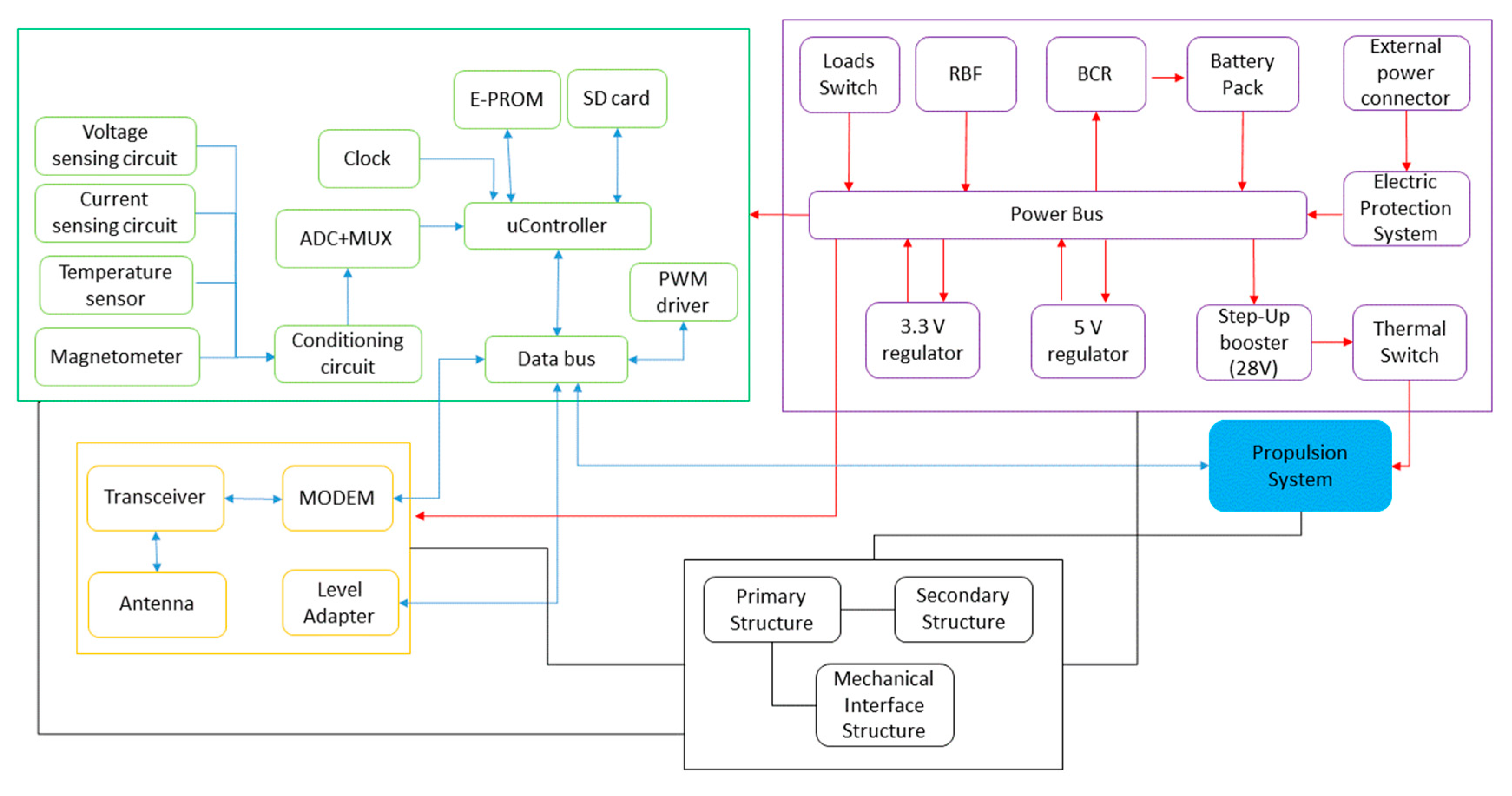
The platform features an Al-alloy 6U structure, which contains the EP system (from to1U up to 4U), the on-board avionics (1U- avionics box), and the PS battery (1U–PS battery slot). An avionics box and a PS battery slot constitute the service module. The EP System includes the Thruster, the Power Processing Unit (PPU) and the Propellant Feed System (PFS), and the propellant tank. The Command and Data Handling (CDH), the Electrical Power System (EPS) and the communication module (COM SYS) constitute the CTP avionics. Two battery packs supply the avionics, while additional battery packs are dedicated to only supply the propulsion system. All the battery packs can be recharged thanks to an external line connected to GSE through EPL Chamber umbilical. The structure is constituted by two truss-like parts joined together through four brackets and closed by panels. The structure is compliant with the CubeSat Design Specification (CDS) for 6U platforms in terms of geometrical interfaces and material (apart from surface coatings). The internal layout can change according to the test: a bulkhead separates the propulsion box from the service module. The EP system under test is fixed to the bulkhead, with the thrust axis along the X geometrical axis of the satellite. The avionics subsystems are based on self-developed electronic boards, representative of the current CubeSat technology. Two lines guarantee the communications between CTP and EPL operators. A Radio-Frequency (RF) link in UHF band and a wired hardline serial line that directly connect the CDH and the Ground Support System (GSS). CDH is based on an ARM-9 microcontroller that manages data and commands, the on-board time and synchronization, the operations and failures. Sensors and acquisition circuits gather the measurements of voltages, currents, temperatures, accelerations, magnetic fields and electrical fields. An EPS motherboard (EPS.M) controls and distributes electrical power to the other subsystems and manages PS battery recharging. An EPS daughter board (EPS.D) manages the avionics (AV) battery packs recharging. Moreover, the EPS.M hosts a circuit (called a Step-Up circuit) that takes the PS battery energy and regulates the voltage towards the EP system in the range 5–28 V, providing a maximum power in output of 60 W. The delivered power is then managed by the PPU of the EP system. Four switches control the activation of the CTP: two switches (called Remove Before Test–RBT) prevent the connection of the battery packs to the bus when the CTP is not in use and during the transportation. Another two switches (called Deployment Switches–DS) separate all the electrical loads from the power bus. The complete block diagram of the CTP is shown in Figure 1: red lines refer to electrical connections, blue lines to the data connections and black lines to mechanical/structural connections.
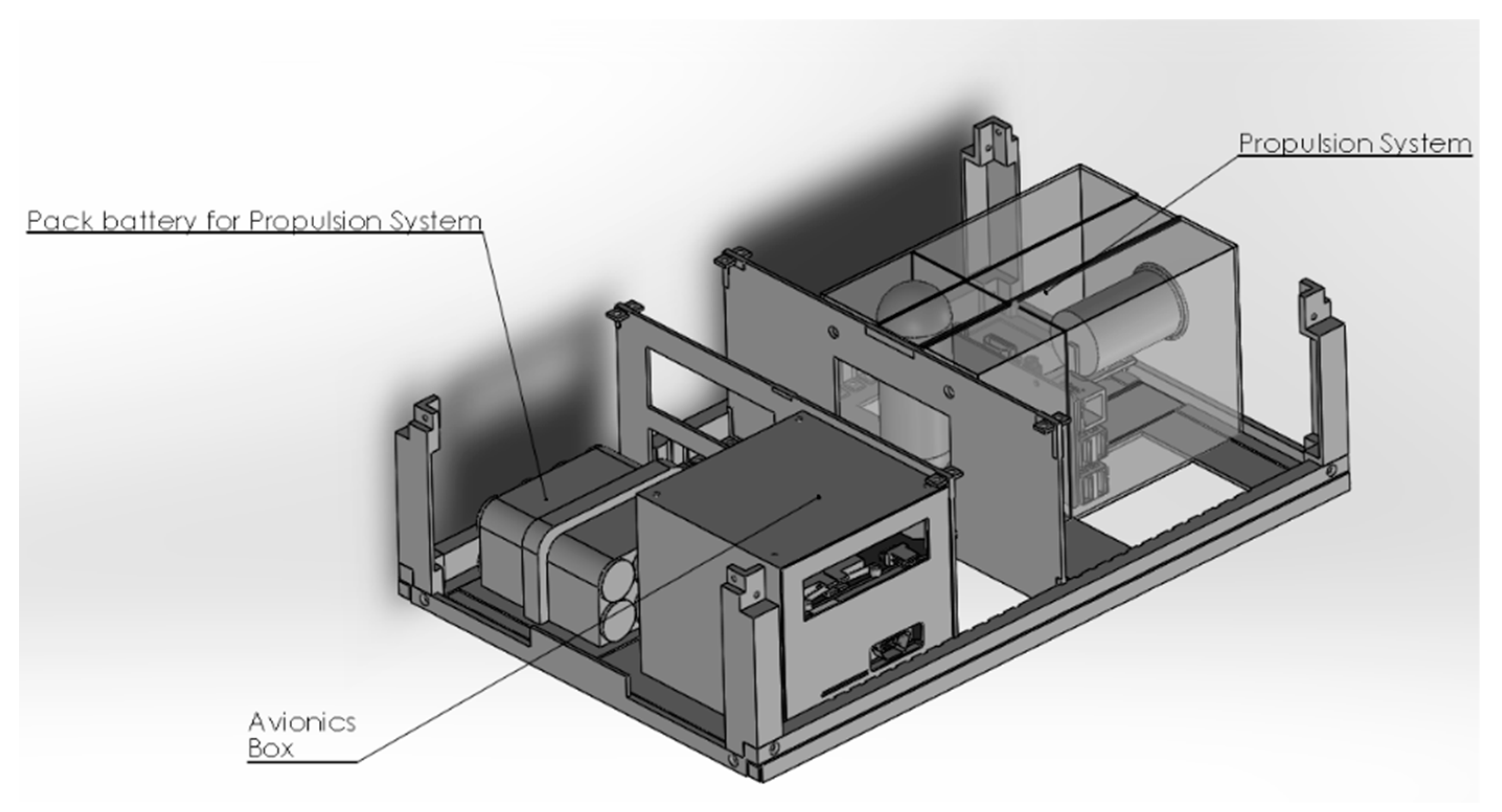
The physical layout of the CTP is shown in Figure 2. The PS box is an up to 4U-size box for hosting the propulsion system. The movable bulkhead fixes the EP system to the structure and separates it from the Service Module containing the avionics and the equipment supporting the test execution.
Operative Modes
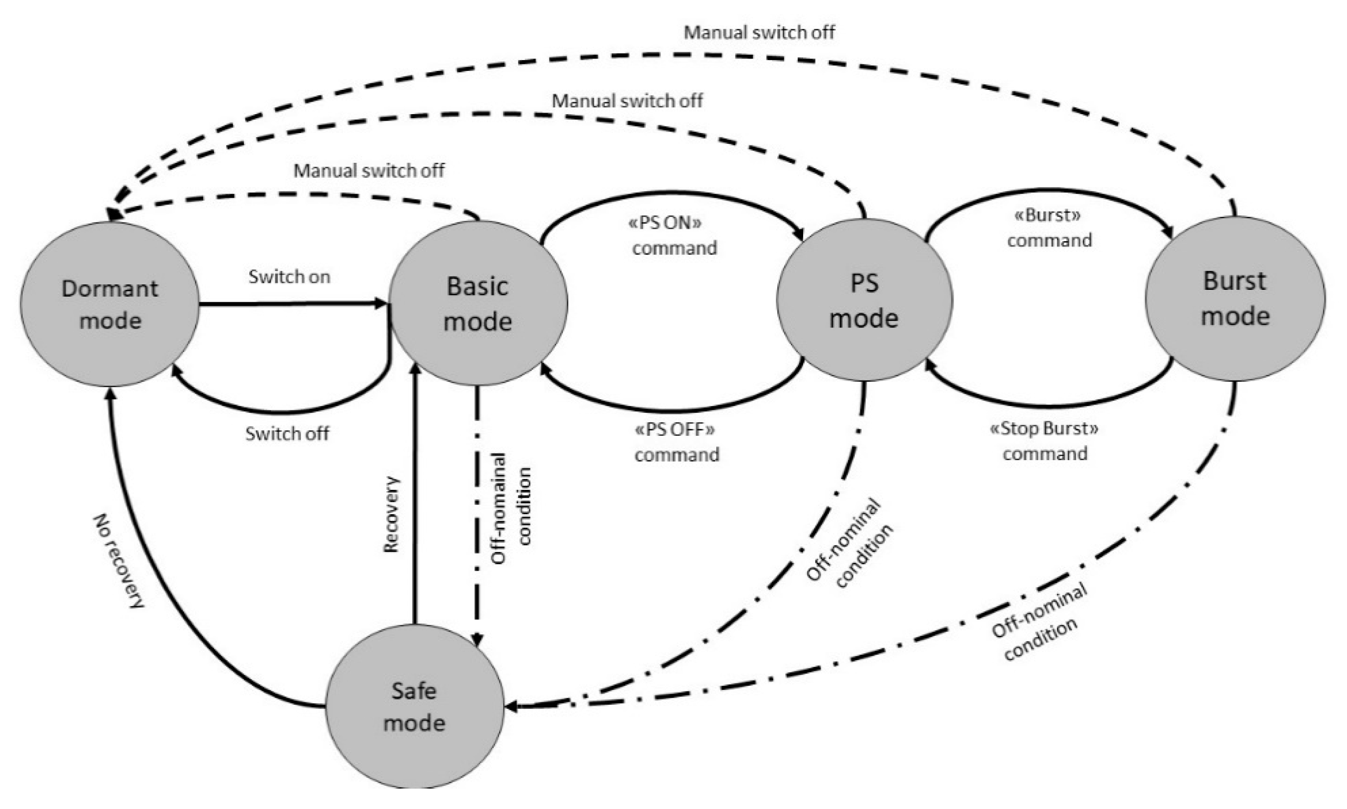
The V&V process is divided into several phases, starting with the test setup of the test elements up to post-processing analyses and CTP stowage. The operative modes (OM) (Figure 3) of the CTP comply with each test phase. The CTP operative modes are:
- Dormant (OM#0): CTP subsystems are switched-off
- Basic mode (OM#1): CTP avionics is active, EP system is off
- PS mode (OM#2): CTP avionics is active, EP system is active, but thruster is off
- Burst mode (OM#3): CTP avionics and the EP system are active, and thruster is activated
- Safe mode (OM#4): CTP avionics is active and recovery operations are performed, while EP system is completely switch-off
Transitions between operative modes can be autonomously executed by the CTP and/or can be commanded from the operators through the GSS. In the Figure 3, dashed lines indicate a transition made with the intervention of the operator, complete lines autonomous transitions, and dashed-dotted lines transitions that could be completed autonomously and/or with the operator intervention. Manual transitions are foreseen when a critical risk that could damage CTP and Ground Support System (GSS)/EPL-Ground Support Equipment (GSE) occurs and the platform must switch off. CTP avionics, PS and thruster burst can be activate/deactivated both with a command from the GSS or directly by the platform when well-identified conditions are checked. Transitions due to off-nominal conditions are managed autonomously by the CTP, while transitions after the recovery routine completion in Safe Mode can be performed both by the operator and directly by the CTP micro-controller.
4. Assembly Integration and Verification
The Assembly Integration and Verification (AIV) plan defines the activities to integrate the CTP, equipment, sub-assemblies and subsystems up to the installation of the CTP in the ESA-ESTEC chamber, called the Small Plasma Facility (SPF). Two main stages of development and verification were identified: the development stage and the integration stage. The development stage aims at demonstrating the design feasibility and supporting the design. The integration stage aims at demonstrating that CTP operates as expected in the laboratory environment and preparing it for the qualification in a relevant environment.
In the development stage, three groups of models are manufactured. The Virtual MockUp (VMU) of each subsystem and the main equipment were developed in the SolidWorks® environment. These models help the optimization/assessment of the CTP layout of parts and sub-assemblies and the interfaces, the validation of the assembly and integration procedures and the checking of the accommodation. A Mass Dummy Unit (MDU) of the structure subsystem was manufactured in PolyLactic Acid (PLA) for testing purposes and fit checks. The MDU is representative of the CTP structure for dimension, mass, external and internal envelope and interfaces. The Electrical and Functional Models (EFM) are functionally representative of the final products in both electrical and software terms. EFMs are of service for the functional assessment of hardware and software, the validation of the procedures, and the preparation of the functional tests for the next phase. The EFMs are representative of the avionics functionalities. They are in the middle between mock-up and Engineering Qualification Models (EQM). EFMs can also be simulators/emulators that substitute hardware and software functionalities or contour conditions. The main EFM is the Development Board of CDH (CDH-EFM), which has been used for the software development, data acquisition circuits implementation, and command transmission.
EQM fully reflects the design of a flight-module from the functional and mechanical point of view. Through the EQM, it is possible to assess the functional performance, including verification of procedures for failure detection, isolation, and recovery and for redundancy management.
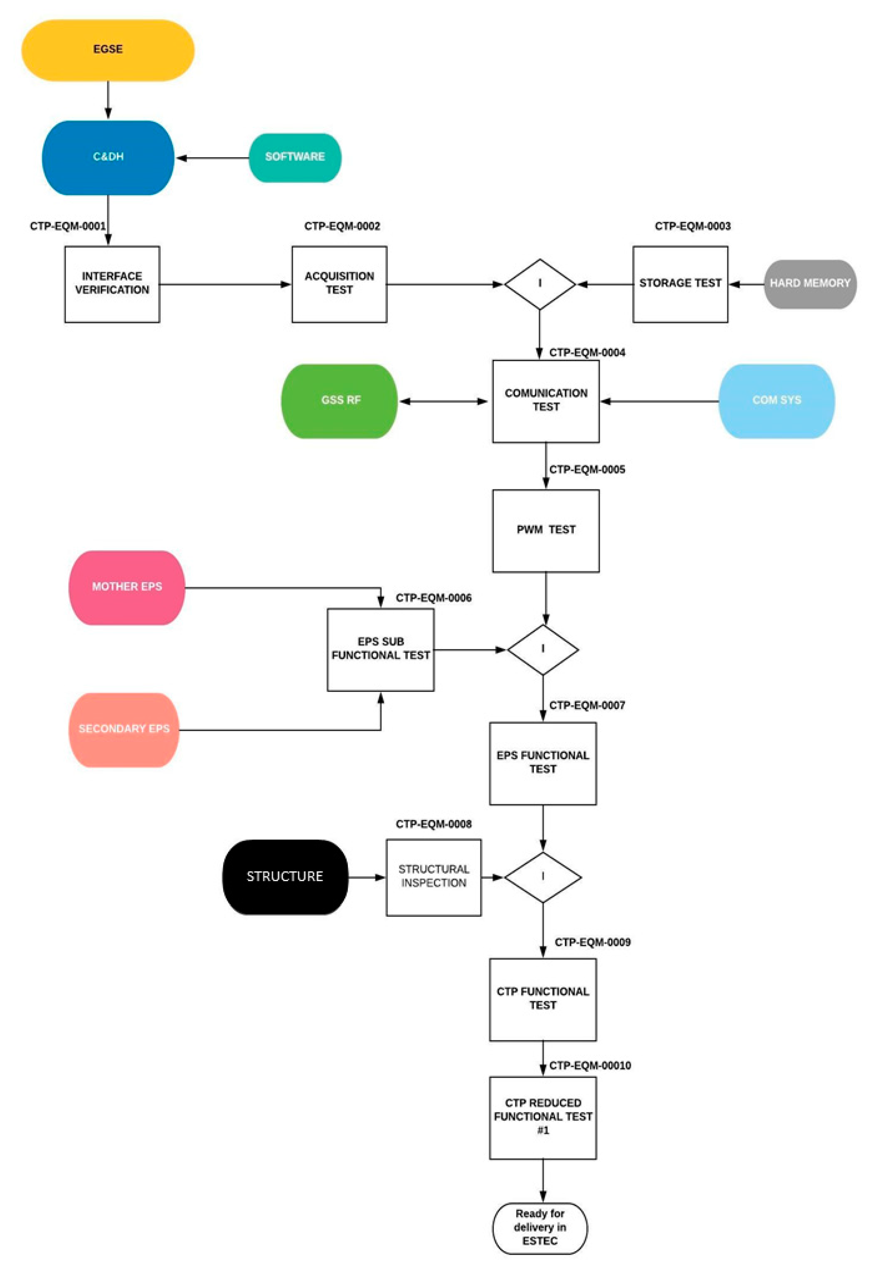
In this paper, the step-by-step sequence of AIV for the EQM model delivered to ESA-ESTEC and integrated in SPF is shown in Figure 4. The planned verifications are:
- Interface Test. The test has to verify all the interfaces and protocols. The interfaces are UART (three communication lines set with RS232 protocol–one is the hardline, the second connects the CDH and the COMSYS and the third is optional towards the EP system), SPI bus to communicate with the data acquisition circuits, and I2C bus towards the magnetometer.
- Acquisition test. This test aims at the validation of the software units and hardware circuits taking care of acquiring data from sensors and setting-up the data exchange with EP system. A 16-channel ADC is mounted on the CDH for the acquisition of temperatures and magnetic field.
- After the integration of the SD-card with the CDH board, the Storage test aims at verifying the capability of storing data in the non-volatile memories (both SD-card and an EPROM).
- Communication test. This test deals with the validation of the software units and hardware for communication via hardline and RF link. The COMSYS board is integrated with the CDH and the GSS guarantees the exchange of data and commands. Moreover, the consistency of the packets with the CRC (Cyclical Redundancy Code) is to be confirmed.
- PWM test. This test aims at confirming the CDH capability of communicating with EPS and setting-up the voltage on the power output towards the EP system through the Step-up circuit. The CDH shall demonstrate the capability to control the voltage according to the request of the EP system under test.
- EPS test. This test aims at verifying the capabilities of the EPS stand-alone (i.e., without any other subsystem). The motherboard EPS is tested to demonstrate the ability of regulation of the bus voltages (3.3 V and 5 V), and control of the discharging and the recharging of the PS battery packs. The same capability is expected for the EPS daughter (EPS.D): regulation of the voltage outputs, and control of the discharging and the recharging of the AV packs. Then, EPS-M and EPS.D are integrated with the CDH and COM SYS sub-assembly completing integration of the avionics box.
- The Structure verification aims at checking the mechanical properties of structural elements. The primary structure is inspected and then the mechanical properties confirmed, taking care of the compliance with the CDS.
- Full functionality test. The functions that CTP shall accomplish to achieve the goals of the program are tested in a single, global test. They include not only the confirmation of the already tested functionalities when EQM is completely assembled but also the verification at system level such as the capability to operate in the different operative modes and during transitions from one mode to another. This test was carried before the integration of any EP system in the CTP. However, the electrical and thermal behaviors of the EP system are (partially) reproduced using three resistors distributed on an aluminum cylinder. In particular, the first resistor (RL1) is installed in the position of the expected output of the thruster, the second resistor (RL2) in the middle of the cylinder and the third resistor (RL3) on the power supply input from the EPS. For the case presented in this paper, the voltage applied to the resistors is 28 V (the worst case for this version of CTP). Moreover, an external PC emulates the data exchange with EP system. A dedicated software generates a stream of bytes (simulating the data output of the CPU of the EP system) that the CDH acquires and handles.
- Reduced Functional Test. The Reduced Functional Test (RFT) is performed to check the main capabilities of CTP and GSS (details are provided in the next paragraph) after major events, for example, before the transportation and the delivery at ESA/ESTEC.
5. Results
In this section, the main results of the AIV campaign on the EQM are reported. The focus is placed on the outputs of the full functionality test because all of the main functionalities, and a great number of the requirements, are verified though this test. The steps of this test include the following:
- Communication and data acquisition in “basic mode” (OM#1): the housekeeping telemetry data are available, but no info is gathered on the EP system, which is power-off.
- Activation of the EP system, before, and the simulation of the thruster activation, after, are commanded by GSS. Moreover, the data for the emulated PS are acquired and saved on board.
- De-activation of the EP system, stopping the thruster simulation, before, and the entire propulsion system, after. Finally, the CTP operates again in basic mode.
- Verification of the main commands—all of the commands for control the nominal and off-nominal conditions—are checked.
The following sub-sections report the results for the entire campaign session.
5.1. Communication, Data Handling and Storage
The two communication lines towards GSS (and the operator) received all of the packets without error in the signal reception and data decoding.
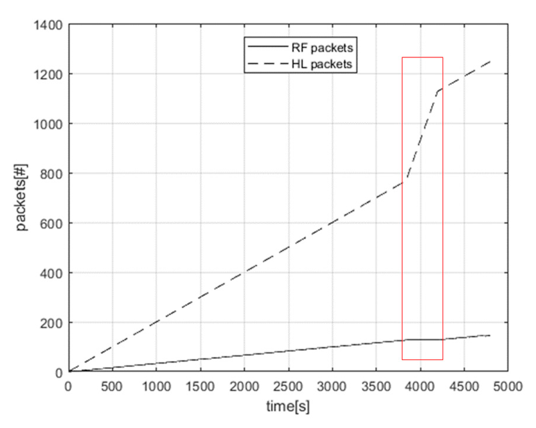
Figure 5 shows the evolution of the number of packets for each line: in OM#1, OM#2, and OM#3, 12 packets/minute are sent via Hardline, while 2 packets/min is the rate of transmission for the RF link. After 3800 s, a recovery function is forced and activated, simulating a misbehavior in sensor acquisition: under this condition, no packets are sent on the RF line while 1 packet/sec is sent on HL (as marked in the red rectangular in the figure).
The storage capability is demonstrated based on the packets being saved without discrepancies or error, both on the EPROM and SD.
5.2. Data Acquisition
Data acquisition is a crucial function, because all measurements and information are fundamental for the process of CTP validation and then for the qualification of the EP systems.
The acquired data on the CTP belong to the following categories:
- Housekeeping data: 5 V Bus, 3.3 V Bus currents, Avionics battery packs and Propulsion battery packs information in terms of voltages, currents, temperatures, and recharging currents are provided.
- PS data: information that the EP system sends through specified digital lines (e.g., USB, UART, SPI, and I2C).
- Test data: measurements of mutual impact between EP system and CTP accomplished with on-board sensors/devices and tools by CTP:
- ○
- Temperatures: 10 NTC sensors are installed in different parts of CTP to monitor the variations in different operative modes
- ○
- Magnetic field: 1 triaxial magnetometer posed inside the avionics box to capture change in the magnetic field in different operative modes
- ○
- Voltages and currents: voltage and currents sensing circuits provide information about the consumption of the EP system under testThese measurements are merged in post processing with the measurements of GSE (sensors and tools) installed outside and with no direct interaction with the CTP. Torsional thrust balance allows the thrust values to be obtained. Mass flow sensors determine the mass flow rates. Microscopes and spectrometers are used in post processing to analyze the chemical residual on the CTP surfaces. A Quartz Crystal Microbalance measures the propellant mass variation per area. Amperemeters and voltmeters, thermocouples, and a Magnetic Field Mapper add other measurements of current, voltage, temperature and magnetic field beyond the CTP measurements. Faraday cups and Langmuir probes provide information for plasma analyses, if necessary. All these data are post-processed to have a completed overview of the behavior of both EP system and CTP. The huge number and type of available sensors allow different set-ups, e.g., CTP can be mounted on a torsional balance or in a thrust stand.
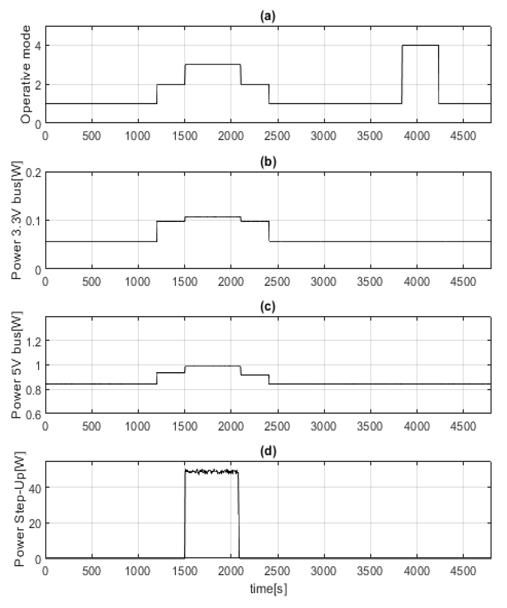
Figure 6 reports the variations of power consumption on a 3.3 V bus, a 5 V bus, and in the output of the Step-Up circuit according to the changes of the operative modes (highlighted in the Figure 6a, where the value 1 indicates the “basic mode”(OM#1), 2 the “PS mode” ”(OM#2), 3 the “burst mode” ”(OM#3), 4 “safe mode” (OM#4)). The consumption of the 3.3 V bus (Figure 6b) stays in the range 78–112 mW and the consumption of the 5 V bus (Figure 6c) remains in the range of 900–1020 mW. These values are compliant with the imposed constraints on the power consumption and acceptable for the avionics system of a 6U platform. In basic mode, only the avionics is active, i.e., all the acquisition lines and the ARM-9 for CDH, the COM SYS board (MODEM and radio-module both in reception and in transmission), and the regulation circuits of the EPS boards. The increments of consumption in OM#2 and OM#3 are due to the activation of peripherals on CDH and supplying lines on EPS towards the EP system interfaces. The consumption on the Step-Up line (Figure 6d) depends on the activation of the resistors (RL) in burst mode. The RLs are powered with the output voltage of the Step-Up circuit (used to control and regulate the voltage towards the EP system). In the presented test session, a voltage of 28 V is applied to RLs observing a peak consumption of 55.8 W and demonstrating the capability of the CTP to work properly in the defined worst case (see requirements in Table 2). Finally, when the safe mode (OM#4) is active (and off nominal conditions occur), the power consumption is almost equal to the basic mode because the avionics subsystem is active and only different software routines on ARM-9 microcontroller are running.
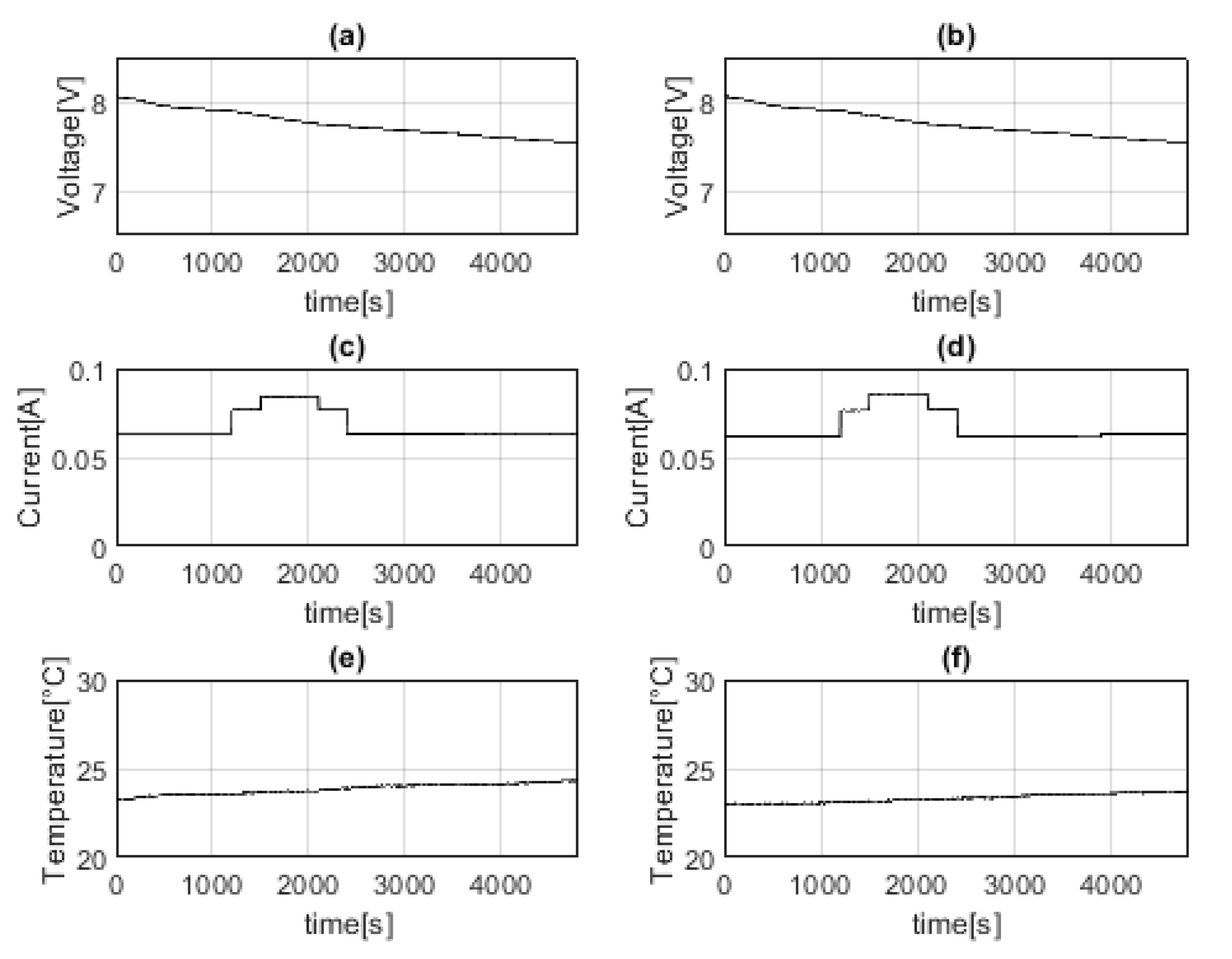
Figure 7 shows the data of the Avionics (AV) battery packs: battery pack voltages decrease, while the currents change according to the operative modes. The temperature (measured by the NTC installed inside the battery pack, between the two Li-Ion cells) slightly increases in the first part of the test while decrease in the second part: the peak values are reached at the end of the burst phase.
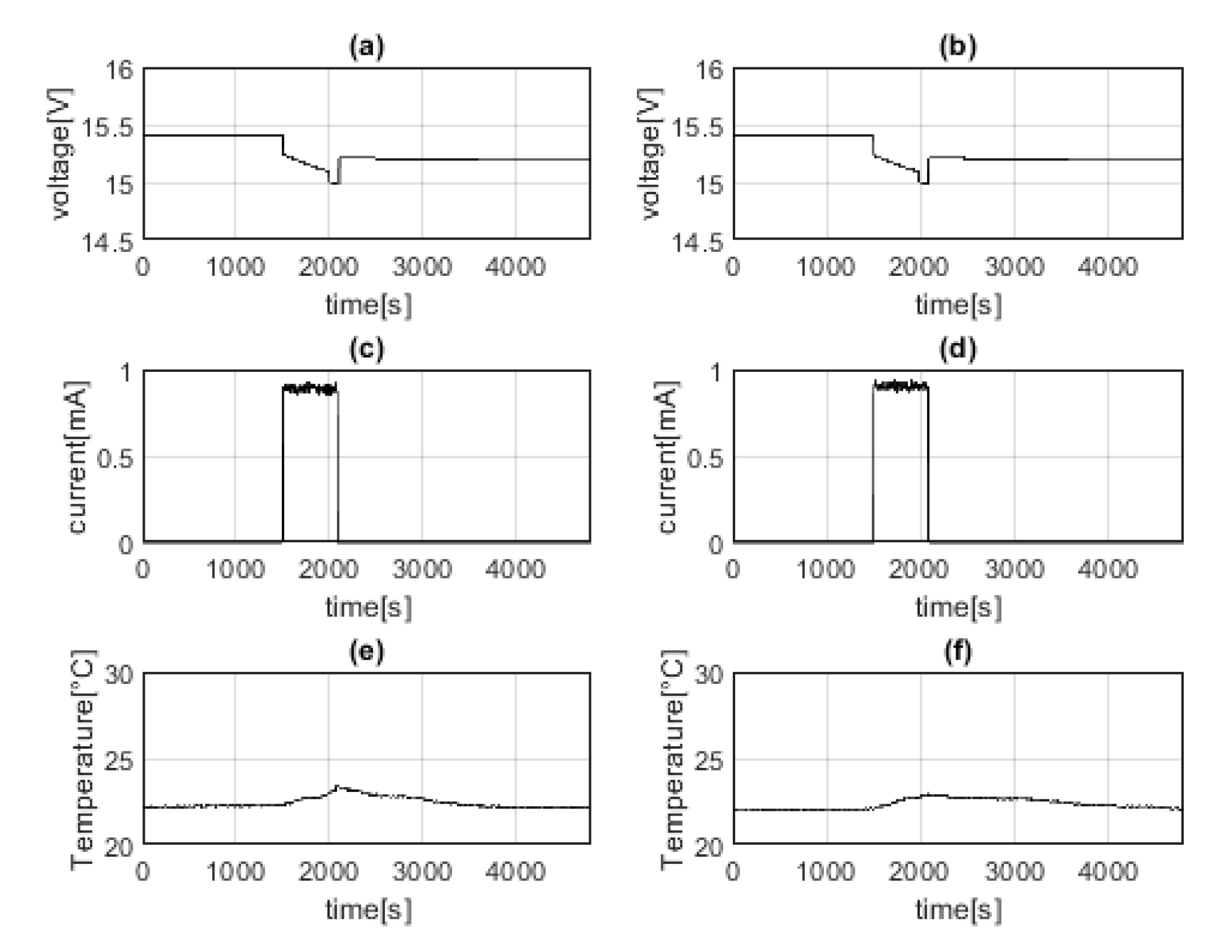
Figure 8 shows that no power is required to the PS battery when the EP system (or the simulated loads) are powered off. When the resistor RLs are activated the voltages decrease, and the temperatures increase up to a maximum temperature of about 28 °C. When the RLs are powered off again the voltages slightly increase, because the Step-Up circuit is not active and, consequently, no loads are connected to the PS battery packs. At the same time, the temperatures decrease and return around the initial values.
All the temperature sensors have an accuracy of 0.1 °C and the calibration was validated using a reference thermo-couple, certified for measurements in the range of −40 °C to 350 °C, with an accuracy of 0.1 °C. The calibration was performed in a thermal chamber using the avionics system (protected in a thermal isolated box), the NTCs, and the certified thermocouple.
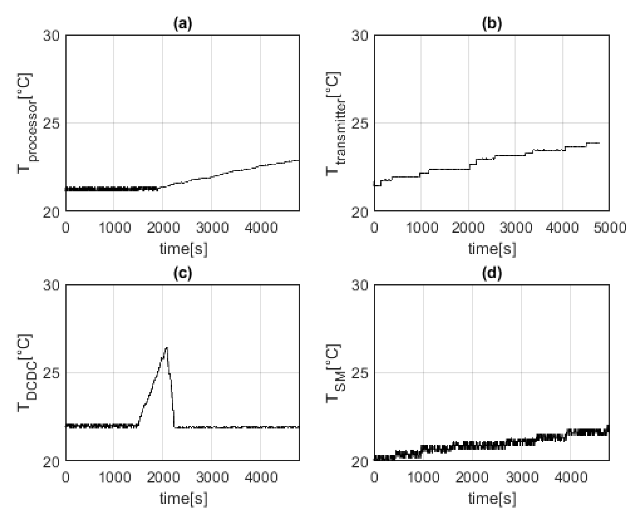
Figure 9 presents the temperature measured at the micro-controller (Figure 9a), the transmitter (Figure 9b), the Step-Up circuit (Figure 9c) and the bulkhead from the side of the service module (Figure 9d).
The temperatures on the processor and bulkhead remain almost constant for the entire test duration while the transmitter temperature increases but remains under 40 °C, which is the operative limit for the component (Figure 9b). The temperature on the Step-Up circuit has a quick increment (Figure 9c) due to the delivery of power to the resistor RLs during the OM#3 operations but it returns to the initial values in less than 3 min after OM#3 deactivation. This trend is also confirmed after the test in the vacuum chamber, where the heat dissipation conditions are different from the laboratory conditions.
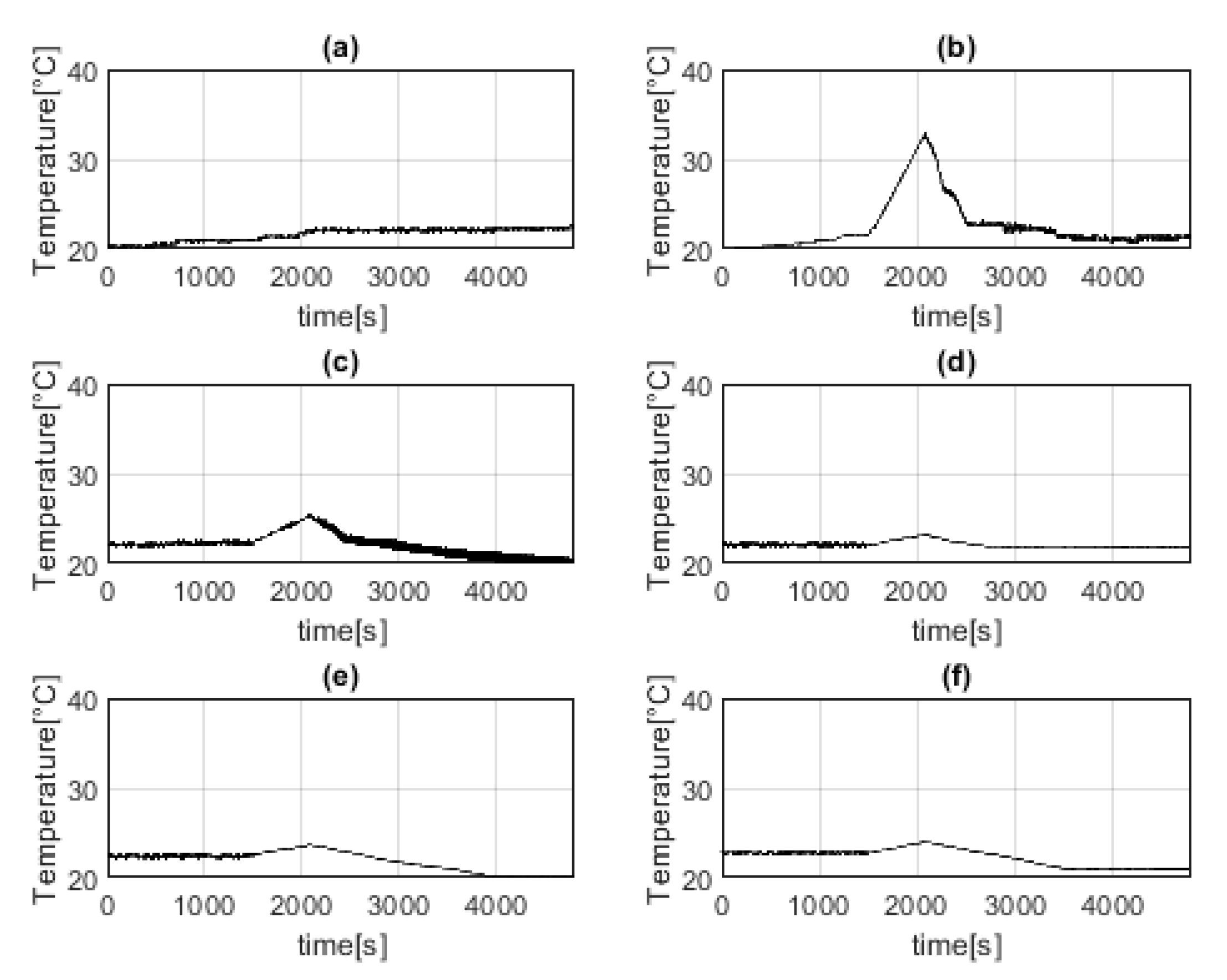
Figure 10 shows the trend of the temperatures in the Propulsion system box. Specifically, one sensor is installed on the bulkhead to the side of the PS box (Figure 10a), one sensor is installed on the opposite side, close to RL1 (Figure 10b), and one sensor is installed on any face (Figure 10c–f).
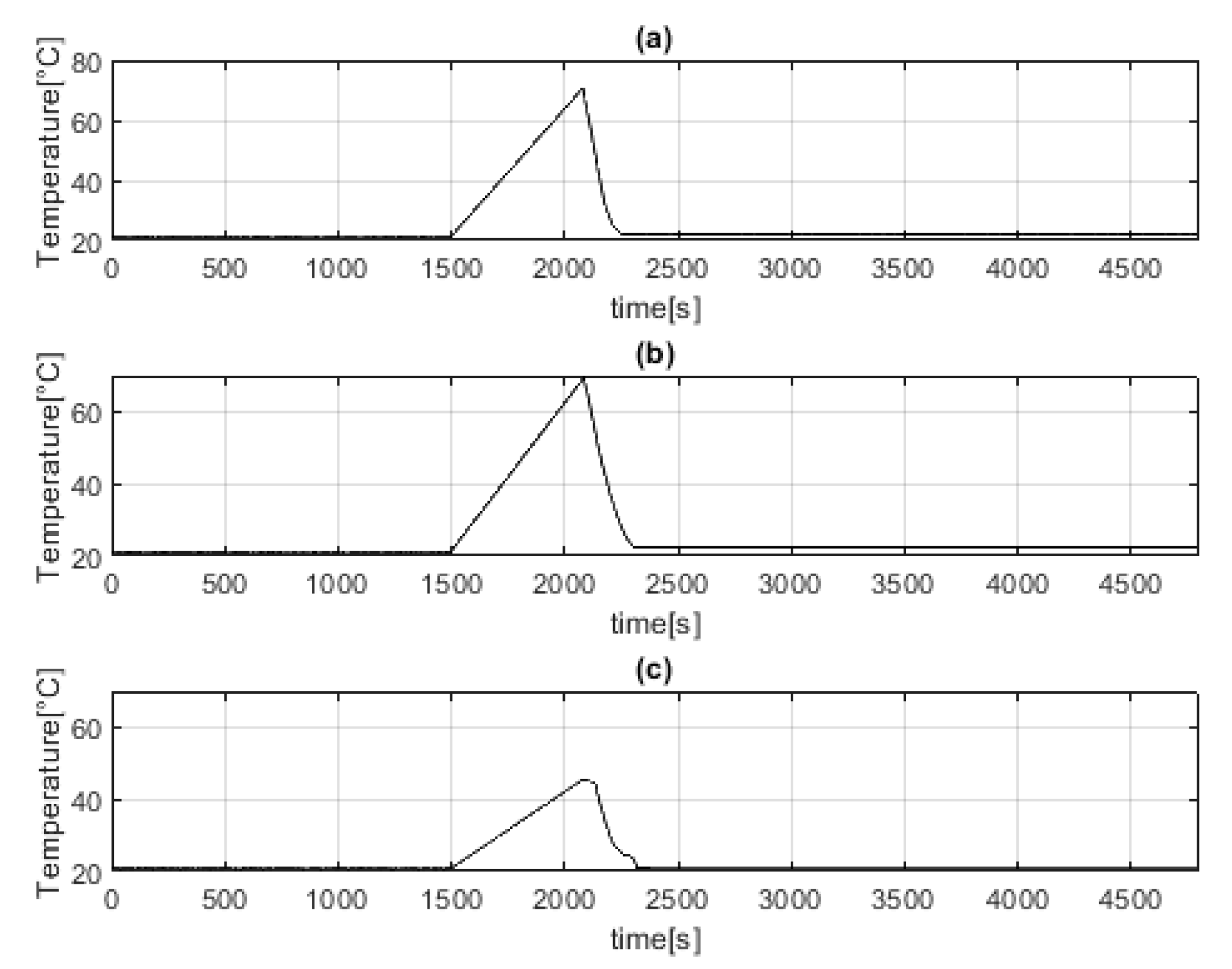
Three sensors are installed in the proximity of the load resistors (Figure 11) in order to assess the heat generated when the burst mode is active. A linear increment (up to 75 °C) of the temperature is observed when the power is delivered to RLs, and a very quick (from 3 to 5 min) cooling down brings again the temperature to the initial values of about 20–21 °C.
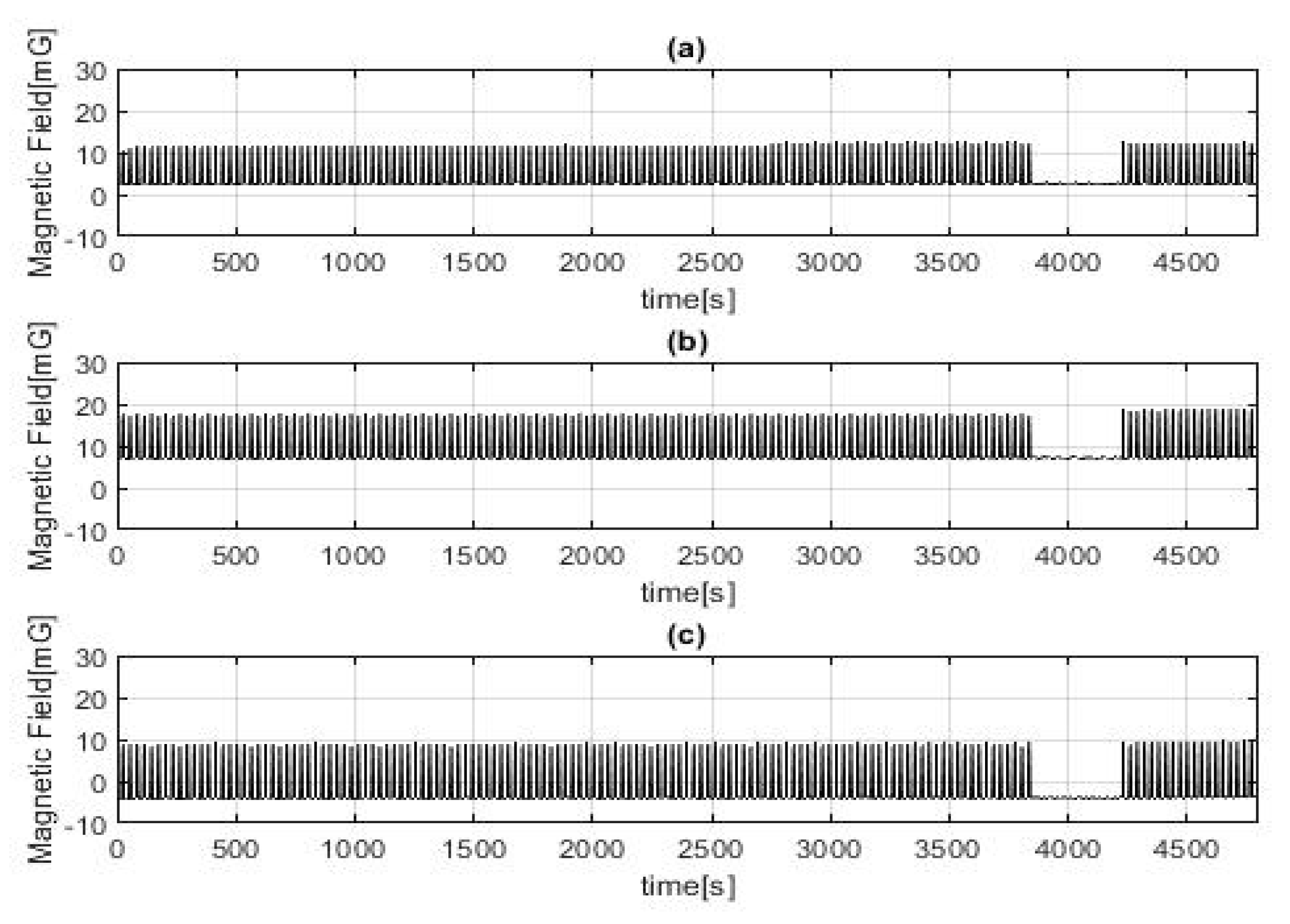
Other information includes the magnetic field (MF), although this is measured under laboratory conditions. Figure 12 shows the trend of the MF (the components X, Y, Z with respect to the coordinates presented in Figure 2 during the test are shown in Figure 12a–c, respectively. Peaks appear when the radio-module transmits the signals (every 30 s); RF transmissions last about 3 s. Finally, no variations of the Magnetic Field occur in the period between 3800 and 4200 s when the OM#4 is active and no RF transmission are permitted.
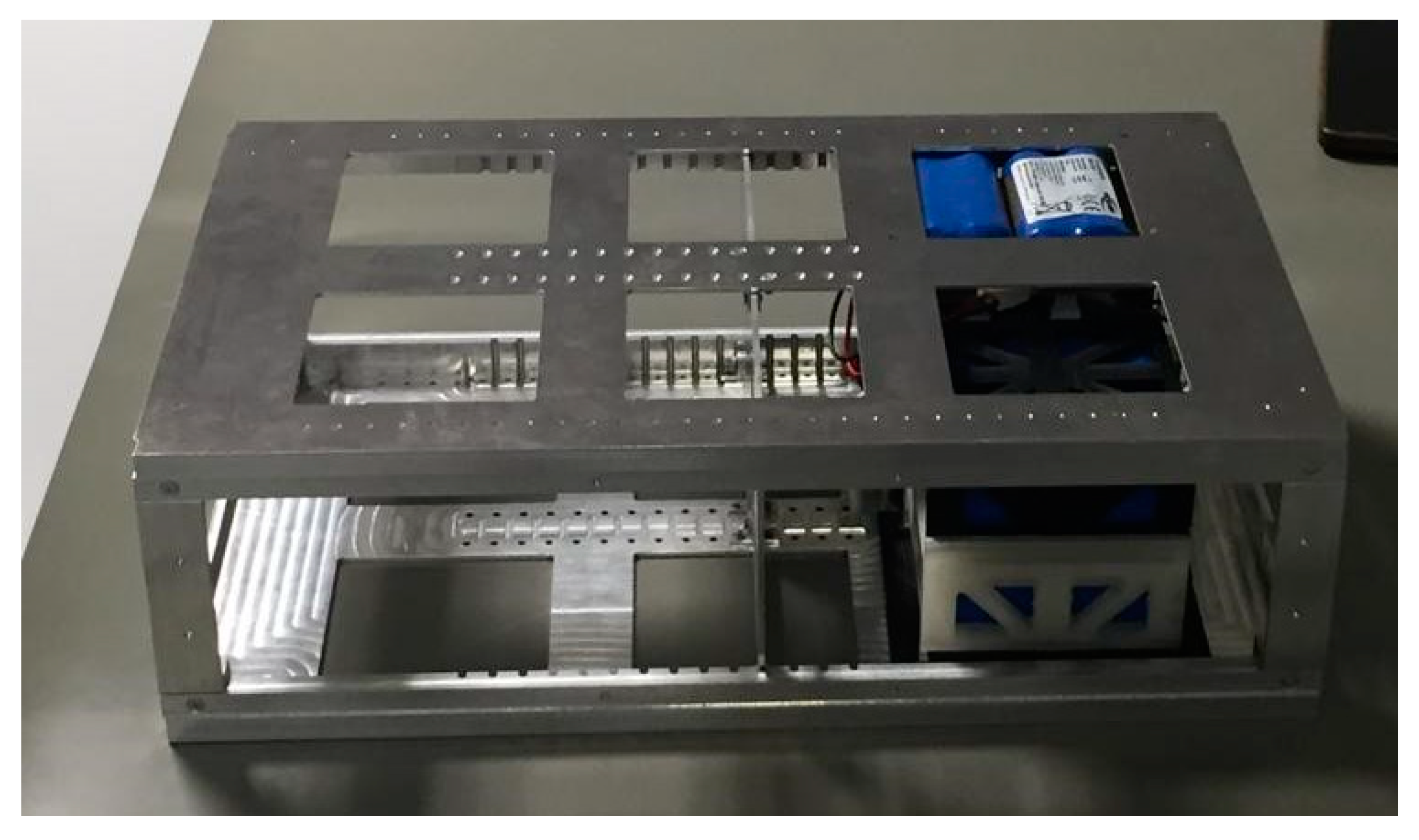
At the end of the full functionality test, the fully integrated CTP (Figure 13) was delivered to ESA/ESTEC.
5.3. Integration in EPL Facilities
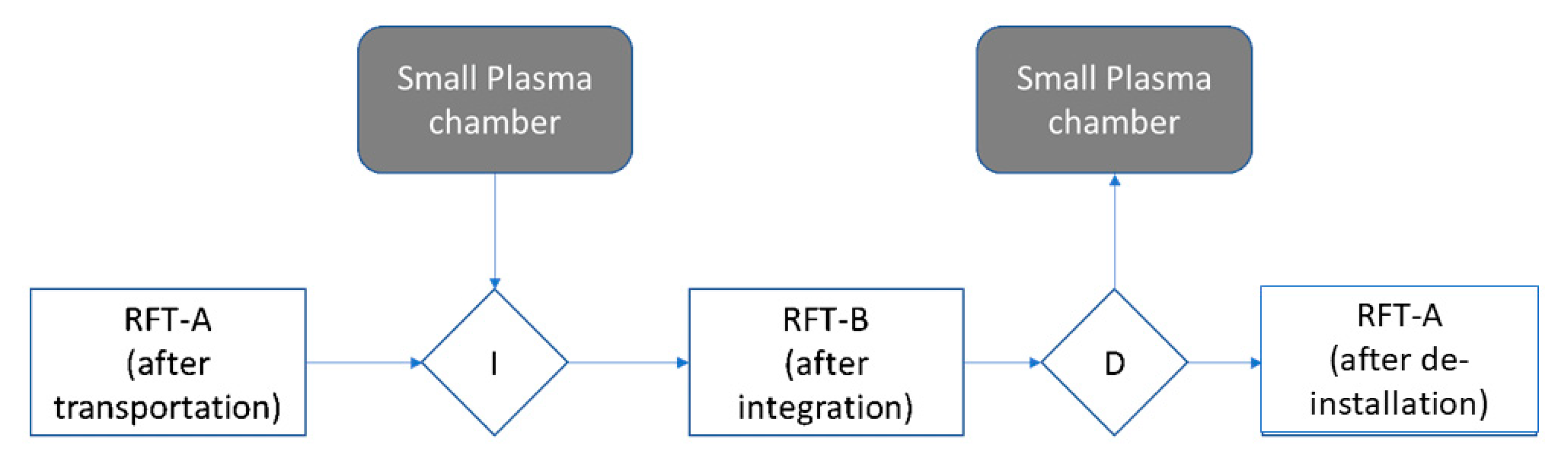
Final integration in the ESA/ESTEC facility–Small Plasma Facility was conducted according the sequence in Figure 14. Three Reduced Functionality Tests (RFT) were required in order to certify that CTP did not loss one or more of its functionalities after an event, such as a transportation, an integration/installation inside the chamber, and /or at the end of a test session or test campaign. RFTs were based on two different setups: (1) The type A RFTs foresee that CTP will be out of the chamber. RFT-A were performed before and after the transportation, and before the stowage. (2) Instead, the type B RFTs were conducted with the CTP installed in the chamber. RFT-B were performed after the integration and before the de-installation of CTP from the chamber. The planned activities for any RFT consists of three steps. (1) Activation of the CTP avionics and check of the consistency of command and data, through the telemetry and commands transmission and reception. (2) Activation and deactivation of the regulated power line towards the EP system and data exchange with the EP system (or its simulation, as in the present case). (3) Complete deactivation of the CTP.
The first RFT was performed after the transportation from Politecnico di Torino to ESA, the second RFT after the integration of the CTP in the EPL chamber, and the third after the de-installation of the CTP from the chamber.
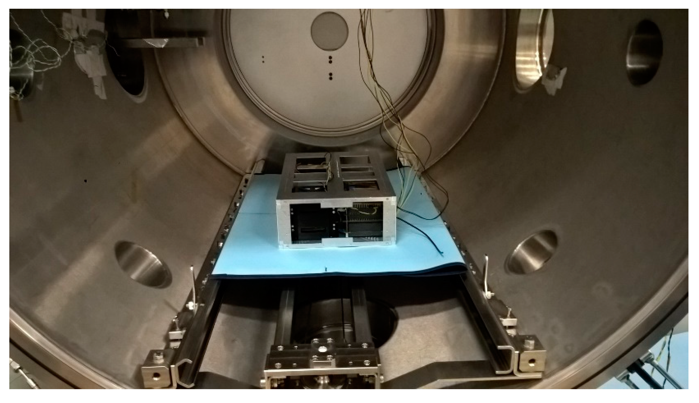
Figure 15 shows a picture of the CTP installed in the SPF chamber at ESA/ESTEC: all the mechanical, electrical and data interfaces were implemented and functionally checked and all the RFTs confirmed that CTP operated as expected in each phase of the integration campaign.
6. Conclusions
CubeSats are projected to have a brilliant future, but their technology still needs improvements and their processes of manufacturing, assembly, integration and verification require greater effectiveness.
Miniaturized electric propulsion systems greatly increase the range of mission architectures achievable with multi-unit CubeSats (6U+). However, a low readiness level, poor integrability with existing small satellites technology and difficulty to effectively complete a test campaign generate a significant gap between electric propulsion solutions and traditional technologies, reducing the number and type of space missions in which the miniaturized electric propulsion systems can be adopted.
The work presented in this paper aims at reducing this gap providing a practical solution to demonstrate that the new electric propulsion systems are not a threat for the other onboard subsystems. In particular, the objective is to assess the mutual effects between the modern platforms and the electrical propulsion systems.
The outcome of the project will guide the thruster and the hosting platform to the qualification for in-orbit demonstration, through the development and validation of a comprehensive test environment, including test platform and test procedures, able to qualify the electric propulsion system design at system level in relevant environment. The platform makes it possible to perform a complete qualification campaign of the entire system evaluating its efficiency through the merging of measurements obtained by sensors mounted inside and outside the CTP. Information about electromagnetic compatibility, thermal environment induced by the operations of the subsystems (specifically, of the propulsion system) and power consumption is combined in order to provide an unprecedented framework to developers of EP system and CubeSat platforms, thus facilitating the transition of products from lab to market.
The test platform is a valuable instrument to increase the level of readiness of a new technology and consolidate the capabilities and robustness of already available CubeSats equipment and subsystems. In the context of the proposed research, future efforts will aim to improve the quality and quantity of the provided data, adding new sensors and acquisition instruments, to increment the flexibility of the interfaces, to support the functional tests on torsional balance, and to extend the test objects range to a wider type of CubeSat technologies.
Funding
This research received no external funding.
Acknowledgments
Politecnico di Torino and the European Space Agency support this work. The author thanks Sabrina Corpino and the students of the CubeSat Team of Politecnico di Torino and ESA-EPL experts for the precious contribution and all the suggestions in the writing of this paper.
Conflicts of Interest
The authors declare no conflict of interest.
References
- Heidt, H.; Puig-Suari, J.; Moore, A.; Nakasuka, S.; Twiggs, R. Cubesat: A New Generation of Picosatellites for Education and Industry Low-Cost Space Experimentation. In Proceedings of the AIAA/USU Conference on Small Satellites, Logan, UT, USA, 11–26 September 2000. [Google Scholar]
- Perez, F.; Modenini, D.; Vázquez, A.; Aguado, F.; Tubío, R.; Dolgos, G.; Tortora, P.; Gonzalez, A.; Lasagni Manghi, R.; Zannoni, M.; et al. DustCube, a nanosatellite mission to binary asteroid 65803 Didymos as part of the ESA AIM mission. Adv. Space Res. 2018, 62, 3335–3356. [Google Scholar] [CrossRef]
- Kim, S.; Nam, T.; Jung, D. Experimental Validation of an Onboard Transient Luminous Events Observation System for VisionCube via Ground Simulation Environment. Aerospace 2018, 5, 100. [Google Scholar] [CrossRef]
- Muri, P.; McNair, J. A Survey of Communication Sub-Systems for Intersatellite Linked Systems and CubeSat Missions. J. Commun. Med. 2012, 7, 290–308. [Google Scholar] [CrossRef]
- Praks, J.; Kestilä, A.; Tikka, T.; Leppinen, H.; Khurshid, O.; Hallikainen, M. AALTO-1 Earth Observation Cubesat Mission—Educational Outcomes. In Proceedings of the 2015 IEEE International Geoscience and Remote Sensing Symposium (IGARSS), Milan, Italy, 26–31 July 2015. [Google Scholar]
- Schoolcraft, J.; Klesh, A.; Werne, T. MarCO: Interplanetary Mission Development on a CubeSat Scale. In Proceedings of the 14th International Conference on Space Operations, Daejeon, Korea, 16–20 May 2016. [Google Scholar]
- Peral, E.; Im, E.; Wye, L.; Lee, S.; Tanelli, S.; Rahmat-Samii, Y.; Horst, S.; Hoffman, J.; Yun, S.H.; Imken, T.; et al. Radar Technologies for Earth Remote Sensing from CubeSat Platforms. Proc. IEEE 2018, 106, 404–418. [Google Scholar] [CrossRef]
- Hand, E. Cubesat networks hasten shift to commercial weather data. Science 2017, 357, 118–119. [Google Scholar] [CrossRef]
- Pittella, E.; Pisa, S.; Pontani, M.; Nascetti, A.; D’Atanasio, P.; Zambotti, A.; Hadi, H. Reconfigurable S-Band Patch Antenna System for Cubesat Satellites. IEEE Aerosp. Electron. Syst. Mag. 2016, 31, 6–13. [Google Scholar] [CrossRef]
- Barnwell, N.; Ritz, T.; Parry, S.; Clark, M.; Serra, P.; Conklin, J.W. The Miniature Optical Communication Transceiver—A Compact, Power-Efficient Lasercom System for Deep Space Nanosatellites. Aerospace 2019, 6, 2. [Google Scholar] [CrossRef]
- Bowen, J.; Villa, M.; Williams, A. Cuebsat Based Rendezvous, Proximity Operations, and Docking in the CPOD Mission. In Proceedings of the AIAA/USU Conference on Small Satellite, Logan, UT, USA, 8–13 August 2015. [Google Scholar]
- Corpino, S.; Caldera, M.; Nichele, F.; Masoero, M.C.; Viola, N. Thermal design and analysis of a nanosatellite in low earth orbit. Acta Astronaut. 2015, 115, 247–261. [Google Scholar] [CrossRef] [Green Version]
- Franchi, L.; Feruglio, L.; Corpino, S.; Mozzillo, R. Model predictive and reallocation problem for CubeSat fault recovery and attitude control. Mech. Syst. Signals Process. 2018, 98, 1034–1055. [Google Scholar] [CrossRef]
- Bouwmeester, J.; Gill, E.K.A.; Speretta, S.; Uludag, M.S. A new approach on the physical architecture of cubesats & pocket qubes. JBIS J. Br. Interplanet. Soc. 2018, 71, 239–249. [Google Scholar]
- Zheng, Z.; Guo, J.; Gill, E. Onboard autonomous mission re-planning for multi-satellite system. Acta Astronaut. 2018, 145, 28–43. [Google Scholar] [CrossRef] [Green Version]
- Levchenko, I.; Bazaka, K.; Ding, Y.; Raitses, Y.; Mazouffre, S.; Henning, T.; Klar, P.J.; Shinohara, S.; Schein, J.; Garrigues, L.; et al. Space micropropulsion systems for Cubesats and small satellites: From proximate targets to furthermost frontiers. Appl. Phys. 2018, 5, 011104. [Google Scholar] [CrossRef]
- Mueller, J.; Hofer, R.; Parker, M.; Ziemer, J. Survey of Propulsion Options for Cubesats. In Proceedings of the 57th JANNAF Propulsion Meeting, Colorado Springs, CO, USA, 3–7 May 2010. [Google Scholar]
- Walker, R.; Liu, M. Integration of Electric Propulsion Systems within Spacecraft—An Overview. In Proceedings of the 33rd International Electric Propulsion Conference, Washington, DC, USA, 6–10 October 2013. [Google Scholar]
- Lemmer, K. Propulsion for CubeSats. Acta Astronaut. 2017, 134, 231–243. [Google Scholar] [CrossRef]
- Obiols-Rabasa, G.; Corpino, S.; Mozzillo, R.; Stesina, F. Lessons Learned of a Systematic Approach for the E-ST@R-II CUBESAT Environmental Test Campaign. In Proceedings of the International Astronautical Congress, IAC, Jerusalem, Israel, 12–16 October 2015; Volume 11, pp. 8474–8482. [Google Scholar]
- Guerrieri, D.C.; Silva, M.A.C.; Cervone, A.; Gill, E. An analytical model for characterizing the thrust performance of a Low-Pressure Micro-Resistojet. Acta Astronaut. 2018, 152, 719–726. [Google Scholar] [CrossRef]
- Stesina, F.; Corpino, S.; Feruglio, L. An in-the-loop simulator for the verification of small space platforms. Int. Rev. Aerosp. Eng. (IREASE) 2017, 10, 50–60. [Google Scholar] [CrossRef]
- Gagne, K.R.; McDevitt, M.R.; Hitt, D.L. A Dual Mode Propulsion System for Small Satellite Applications. Aerospace 2018, 5, 52. [Google Scholar] [CrossRef] [PubMed]
- Montag, C.; Starlinger, V.; Herdrich, G.; Schönherr, T. A High Precision Impulse Bit Pendulum for a Hardware-in-the-Loop Testbed to Characterize the Pulsed Plasma Thruster PETRUS 2.0. In Proceedings of the 7th Russian-German Conference on Electric Propulsion, Giessen, Germany, 21–26 October 2018. [Google Scholar]
- Stesina, F.; Corpino, S.; Calvi, D.; Saccoccia, G.; Gonzalez Del Amo, J.; Bosch Borras, E. Design of a Test Platform for Miniaturized Electric Propulsion. In Proceedings of the 69th International Astronautical Congress, Bremen, Germany, 1–5 October 2018. [Google Scholar]
- Krejci, D.; Reissner, A.; Seifert, B.; Jelem, D.; Hörbe, T.; Plesescu, F.; Friedhoff, P.; Lai, S. Demonstration of the IFM nano-FEEP Thruster in Low Earth Orbit. In Proceedings of the 4S Symposium, Sorrento, Italy, 28 May–1 June 2018. [Google Scholar]
- Rafalskyi, D.; Aanesland, A. A Neutralizer-Free Gridded Ion Thruster Embedded into A 1U Cubesat Module. In Proceedings of the 35th International Electric Propulsion Conference, Atlanta, GA, USA, 8–12 October 2017. [Google Scholar]
- Lascombes, P.; Henri, D. Electric Propulsion for Small Satellites Orbit Control and Deorbiting: The Example of a Hall Effect Thruster. In Proceedings of the Space Ops Conference, Marseille, France, 28 May–1 June 2018. [Google Scholar]
- Manente, M.; Trezzolani, F.; Magarotto, M.; Fantino, E.; Selmo, A.; Bellomo, N.; Pavarin, D. Regulus: A propulsion platform to boost small satellite missions. Acta Astronaut. 2019, 157, 241–249. [Google Scholar] [CrossRef]
- Montag, C.; Herdrich, G.; Schönherr, T. Modifications and Experimental Analysis towards an Update of the Pulsed Plasma Thruster PETRUS. In Proceedings of the 35th International Electric Propulsion Conference, Atlanta, GA, USA, 8–12 October 2017. [Google Scholar]
- Stelwagena, I.F.; de Jonga, M.J.; Xua, W.; Viseea, R.; Grustan-Gutierrezb, E.; Redwoodb, O.; Huhb, J.; Grayc, H.; Giannettic, V.; Liljeholmd, L.; et al. Development of a High-Performance Low-Cost PPU for an Electrospray Colloid Electric Propulsion System for Small Satellite Applications. In Proceedings of the 69th International Astronautical Congress (IAC), Bremen, Germany, 1–5 October 2018. [Google Scholar]
- Courtney, D.G.; Li, H.Q.; Lozano, P. Emission Measurements from Planar Arrays of Porous Ionic Liquid Ion Sources. IOP J. Phys. D Appl. Phys. 2012, 45, 485203. [Google Scholar] [CrossRef]
- Tummala, A.; Dutta, A. An Overview of Cube-Satellite Propulsion Technologies and Trends. Aerospace 2017, 4, 58. [Google Scholar] [CrossRef]
- Siddiqui, M.U.; Cretel, C.; Synowiec, J.; Hsu, A.G.; Young, J.A.; Spektork, R. First Performance Measurements of the Phase Four RF Thruster. In Proceedings of the 35th International Electric Propulsion Conference, Atlanta, GA, USA, 8–12 October 2017. [Google Scholar]
Figure 1.
CTP block diagram.

Figure 2.
CTP design and layout.

Figure 3.
Operative modes and their transitions.

Figure 4.
AIV process for the EQM.

Figure 5.
Number of packets for communication line.

Figure 6.
Power consumption vs. operative mode: (a) active operative modes, (b) power consumption of 3.3 V bus, (c) power consumption on 5 V bus, (d) power consumption in output of Step-up circuit.
Figure 6.
Power consumption vs. operative mode: (a) active operative modes, (b) power consumption of 3.3 V bus, (c) power consumption on 5 V bus, (d) power consumption in output of Step-up circuit.

Figure 7.
AV batteries: (a) voltage of AV battery 1, (b) voltage of AV battery 2, (c) current of AV battery 1, (d) current of AV battery 2, (e) temperature of AV battery 1, (f) temperature of AV battery 2.
Figure 7.
AV batteries: (a) voltage of AV battery 1, (b) voltage of AV battery 2, (c) current of AV battery 1, (d) current of AV battery 2, (e) temperature of AV battery 1, (f) temperature of AV battery 2.

Figure 8.
PS batteries. (a) voltage of PS battery 1, (b) voltage of PS battery 2, (c) current of PS battery 1, (d) current of PS battery 2, (e) temperature of PS battery 1, (f) temperature of PS battery 2.
Figure 8.
PS batteries. (a) voltage of PS battery 1, (b) voltage of PS battery 2, (c) current of PS battery 1, (d) current of PS battery 2, (e) temperature of PS battery 1, (f) temperature of PS battery 2.

Figure 9.
Avionics temperatures: (a) temperature of the processor, (b) temperature of the transmitter, (c) temperature of the Step-Up circuit, (d) temperature on the bulkhead-avionic box side.
Figure 9.
Avionics temperatures: (a) temperature of the processor, (b) temperature of the transmitter, (c) temperature of the Step-Up circuit, (d) temperature on the bulkhead-avionic box side.

Figure 10.
Temperatures in the PS box: (a) temperature on the bulkhead–PS box side, (b) temperature on the internal face opposite to the bulkhead, (c–f) temperatures on the other faces of the PS box, −y, +y, −z, and +z, respectively.
Figure 10.
Temperatures in the PS box: (a) temperature on the bulkhead–PS box side, (b) temperature on the internal face opposite to the bulkhead, (c–f) temperatures on the other faces of the PS box, −y, +y, −z, and +z, respectively.

Figure 11.
Temperatures of simulated loads (a) temperature on RL1, (b) temperature on RL2, (c) temperature on RL3.
Figure 11.
Temperatures of simulated loads (a) temperature on RL1, (b) temperature on RL2, (c) temperature on RL3.

Figure 12.
Magnetic Field from tri-axial magnetometer: (a) Magnetic Field along the X-sensor axis, (b) Magnetic Field along the Y-sensor axis, (c) Magnetic Field along the Z-sensor axis.
Figure 12.
Magnetic Field from tri-axial magnetometer: (a) Magnetic Field along the X-sensor axis, (b) Magnetic Field along the Y-sensor axis, (c) Magnetic Field along the Z-sensor axis.

Figure 13.
Fully integrated CTP.

Figure 14.
Steps of the final integration in SPF.

Figure 15.
Integration of CTP in SPF.


Table 1.
List of main miniaturized electric propulsion system considered in this work.
| Developer | EP System Technology |
|---|---|
| Enpulsion–Austria | IFM-FEEP [26] |
| ThrustMe–France | NPT30-Gridded ion thruster [27] |
| ExoTrail–France | EXO-Hall effect thrusters [28] |
| T4I–Italy | Regulus [29] |
| Institute of Space Systems (IRS) at University of Stuttgart–Germany | PETRUS-coaxial, breech fed and low energy PPT [30] |
| GOMSPACE–Denmark | HiperLoc-EP–Electrospray [31] |
| Busek Co Inc.–USA | BET–Electrospray [32] |
| ACCION–USA | IET5000-Electrospray [33,34] |
Table 2.
High level requirements.
| Statement |
|---|
The interactions between Propulsion systems and CubeSats shall be evaluated in term of
|
| CTP shall provide/support the direct/indirect measurements of thrust, mass, electrical and diagnostics parameters |
| Only complete propulsion systems shall be considered (stand-alone thrusters are not object of the test). Complete EP systems include (at least): thruster, tank, PPU (Power Unit), PFU (Propellant Feed Unit), where required |
| CTP shall use CubeSat technology and Commercial Off the Shelf components (MIL or S items can be included in case no COTS are available or for safety critical technology) |
| CTP shall be integrated in the test facilities (e.g., CORONA or SPF) at Propulsion Laboratory (ESA/ESTEC) |
| CTP shall guarantee one failure-points protection with respect to the operators and the test operations |
| CTP shall be compliant with the 6U CubeSat Design Specification |
| CTP shall provide voltage to propulsion system under test up to 2A @28V (peak power 56 W) |
| CTP shall provide voltage to propulsion system in the range 5–28 V |
| No external power supplier shall be adopted to supply the CTP during the test (a part for battery recharging activity) |
| CTP shall exchange data towards propulsion sys using one or more of these interfaces: UART, USB, I2C, SPI, CAN bus. |
| CTP shall host the EP system with a volume up to 4U |
| CTP operations shall be managed both autonomously by the on-board systems and by the operators through a dedicated interface human/CTP. |
| Human operator shall have a higher priority in the decision-making activity during every test campaign |
| The program shall reflect standard procedures and methods used in the industrial field and recognized by the Agency (ESA) |
© 2019 by the author. Licensee MDPI, Basel, Switzerland. This article is an open access article distributed under the terms and conditions of the Creative Commons Attribution (CC BY) license (http://creativecommons.org/licenses/by/4.0/).
Share and Cite
MDPI and ACS Style
Stesina, F. Validation of a Test Platform to Qualify Miniaturized Electric Propulsion Systems. Aerospace 2019, 6, 99. https://doi.org/10.3390/aerospace6090099
AMA Style
Stesina F. Validation of a Test Platform to Qualify Miniaturized Electric Propulsion Systems. Aerospace. 2019; 6(9):99. https://doi.org/10.3390/aerospace6090099
Chicago/Turabian StyleStesina, Fabrizio. 2019. "Validation of a Test Platform to Qualify Miniaturized Electric Propulsion Systems" Aerospace 6, no. 9: 99. https://doi.org/10.3390/aerospace6090099
Note that from the first issue of 2016, this journal uses article numbers instead of page numbers. See further details here.