1. Introduction
As the capabilities of small satellites—defined by NASA as having masses less than 180 kg—have matured, mission designers have begun to consider their use in formation flying mission architectures that would be impossible and/or cost-prohibitive to perform with larger satellites. Two immediate examples are multi-point Earth observations or synthetic aperture arrays for deep space exploration; an extensive compilation of formation flying missions is found in the recent review by Bandyopadhyay et al. [
1] Small satellites are uniquely suited for these types of missions, as all of the elements can be launched simultaneously and for a fraction of the cost of traditional missions. There has been particular interest in missions designed around the CubeSat platform since the supporting infrastructure for launching and deploying satellites built to this standard is already in place. Indeed, a number of CubeSat-based missions are in development that demonstrate the potential of the platform and the demand for continued improvement of the supporting technologies [
2,
3,
4].
Much of the formation flying literature has focused, and rightly so, on the aspects of dynamics and control. However, the implementation of such control strategies hinges upon the existence and availability of the associated satellite technology and hardware. Although current small satellites designs are considerably more capable than those in previous generations, the hardware and system technology still lag mission concepts; indeed, additional satellite subsystem development is required to support new mission concepts. A recent review of the state of small satellite technology is given in the 2015 NASA Ames Small Spacecraft Technology State of the Art technical report [
5]. Perhaps the most critical of these subsystems is that of propulsion; this subsystem must be capable of providing extremely low level impulses needed for the relative position and orientation control necessary to enable precise formation flying [
6,
7,
8]. Small satellite attitude control thrusters are particularly challenging as they must provide reliable, low impulse-bit operation while conforming to the size, weight, power, and cost constraints of the form factor. In addition to the technical challenges these propulsion systems must address, there are often regulatory hurdles that impede their adoption for small satellites [
9,
10]. These regulations require propulsion systems to meet range safety and secondary payload requirements that limit the storage tank pressurization, amount of stored chemical energy, and toxicity of the propellant. Such requirements immediately eliminate many chemical-based propulsion options, and limit the efficacy of others.
We note in passing that electric propulsion concepts have also been proposed in recent years for CubeSat platforms [
11,
12,
13,
14]. These include electrospray thrusters, pulsed-plasma thrusters (PPT) and field-emission electric propulsion thrusters (FEEP) among others. Readers interested in non-chemical options may wish to consult the cited references for greater details. Based on its inherently low thrust levels and high specific impulse, electric propulsion would seem to be a natural consideration for formation-flying applications. However, these systems pose challenges in terms of system mass and power requirements that raise questions as to their viability for the CubeSat platform. As such, we restrict our focus here to chemical-based options.
A new small satellite propulsion attitude control concept is currently in development at the University of Vermont with the above limitations and considerations in mind. The proposed system consists of a physical array of discrete, single-use microthrusters, each containing a non-toxic solid propellant based on a chemical blowing agent (CBA). The operation of the thruster is triggered by the thermal decomposition of the CBA into hot, pressurized gas. The packaging into an array permits multiple firings by the system. Based on the goal of providing thrust levels (∼1 N) and impulse-bits (∼0.1 N·s) necessary for small attitude adjustments, our design calculations show that this array would require MEMS-manufacturing techniques. This paper describes the design concept for the system, the development of meso-scale proof-of-concept thruster, and its performance characteristics under testing. The experimental results are supplemented by numerical simulations of the thruster firing to better understand the observed performance within the context of the transient gas dynamics within the device. The results of these efforts point to the viability of a system that can be mass-produced at a low-cost for future small satellite formation flying missions.
2. Design Concept
The proposed system is intended to offer relative position and attitude control of a CubeSat-class or smaller spacecraft operating in a constellation architecture. The target performance characteristics for the design are shown in
Table 1; these performance parameters are selected to provide the satellite with the ability to maintain relative orientation and position in the face of disturbance torques and/or to allow for re-orientation with milli-arcsecond resolution.
To address the regulatory challenges typically associated with chemical propellants, this system is designed to use a chemical blowing agent as the propellant. Blowing agents are a family of chemical compounds that produce a significant volume of gas as a result of thermally-induced decomposition. They are commonly used as an additive in polymer manufacturing and food production to reduce the density of the surrounding medium [
15,
16]. They are attractive as a potential propellant since they are non-toxic, inert at temperatures below the activation temperature. Moreover, CBAs are low in cost due to their extensive use in other industries.
To achieve the minimum thrust and impulse bits required, our thruster concept envisions an individual thruster “element” consisting of a 32 × 32 × 10
m propellant chamber/plenum, paired with an electro-thermal heating element and a converging-diverging nozzle. The concept further envisions that the individual thrusters would be packaged as an array of microthrusters with individual decomposition chambers, with each array being placed at the corners of the CubeSat to offer control (
Figure 1). Based on current MEMS-manufacturing capabilities, it is deemed feasible to create a 7 mm square array of these cells, with spacing for structural and thermal integrity, consisting of 19,600 individual cells, each designed to provide ∼1
N of thrust.
The operation of the microthruster array is straightforward. Every element in the array can be addressed and ignited individually, simultaneously or in controlled sequences to produce the required vector thrust for the specific application. During the manufacturing process, a diaphragm is inserted to cover the propellant chamber that is designed to burst at a predetermined plenum pressure. Potential shell coating materials with MEMS applications include ceramic polymer compositions, polymer composites, and polymer metal composites. This design offers high production principals due to its simplicity and very few steps of assembly, which could be made in strip or sheet forms. Further, the array system can be directly integrated into other interceptor parts reducing even further the assembly, manufacturing, cost and weight.
The division of the propellant into small quantities also results in safer operation, and minimizes the possibility of hazard occurring in the storage of the propellant. The propellant powder can be transported safely if it is packed in small containers or capsules and then packaged in each separate cell. These capsules are safe even in external fire and can be extinguished easily by water spray. The absence of toxic products in the decomposition reaction makes the propellant and the resulting microthruster array environmentally friendly in every stage from the manufacturing of the propellant to array assembly.
While this system is conceptually straightforward, there are outstanding questions regarding the performance of the blowing agent as a propellant and the impact of the diaphragm-rupture event on the performance of the thruster. The following sections describe the development of a meso-scale thruster prototype that is used to study the performance of the blowing agent, and the development of a numerical model that was used to study internal flow dynamics after the diaphragm rupture.
3. Proof of Concept Thruster Design
3.1. Design Overview
The design and analysis of an individual thruster is the natural starting point for the characterization and optimization of this propulsion concept, and is the focus of the remainder of this article. A single solid propellant thruster with nozzle exit at ambient pressure was thus designed and tested.
Figure 2 shows a schematic diagram of the complete propulsion system with key components labeled.
A ubiquitous component of the thruster design is the converging-diverging supersonic nozzle which produces thrust by efficiently converting the thermal energy of the inlet gases into kinetic energy at the outlet. In this meso-scale prototype, the nozzle was designed with 2 mm throat and an expander half angle of
based on design considerations for supersonic micronozzles presented by Louisos et al. [
17]. The nozzle geometry, shown in
Figure 3, is symmetric about the throat and has an outlet area expansion ratio of 36. Both the propellant chamber and the nozzle were fabricated using additive manufacturing and thermally resistant plastic based filament (i.e., polylactic-acid/PLA) with melting temperature 180–220
C.
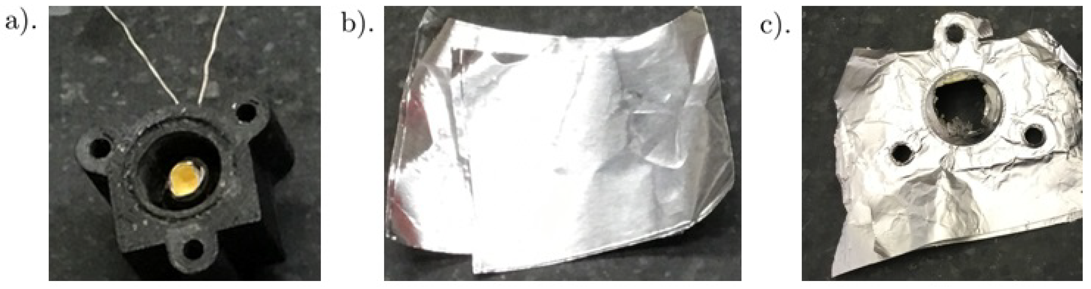
In the current thruster design, the propellant decomposition chamber houses a nichrome heating element that holds an aluminum foil packet containing a mass of the CBA powder (see
Figure 4a). The heater is designed for maximum surface area coverage of the powder using a coiled geometry. Additionally, hollow cylinders are employed to prevent direct contact between the nichrome wire and the decomposition chamber; such direct contact was found to thermally damage the plastic chamber after a few tests. The electrical leads of the nichrome heating element are passed out of the chamber via ferrule elements to provide external triggering.
The rupture disc is a single-use pressure relief device used to separate nozzle and chamber components until the maximum decomposition pressure condition is achieved. With no moving parts or release times, the rupture disc is a simple, reliable, and fast acting mechanism to release the pressure (
Figure 4b,c). In this study, aluminum 8011 alloy was used for its combination of light weight and corrosion-resistance. The burst pressure is adjusted by varying the number of layers; in this study, 4–8 layers were considered.
A key consideration of this design is that of modularity, as the chamber, nozzle, and mounting cart are all capable of being re-configured. Consequently, longer chambers and arbitrary nozzle dimensions can be fabricated according to the application, making the fabrication process effective and efficient. Additionally, for this design, the rupture disc and the igniter can each be located at different positions and in different configurations. For the rupture disc, obvious locations include the entrance to the nozzle or at the nozzle throat. The position of the rupture disc leads to different flow behavior within the nozzle; this is discussed in detail in the numerical simulations described in
Section 5. The igniter/propellant assembly can also be packaged in different configurations. The experiments have shown that the configuration impacts the decomposition rate of the propellant and the completeness of the decomposition, and hence the overall microthruster performance.
3.2. Performance Estimation
The propellant used in the experiments was the commercial blowing agent AccuCell-196 provided by KibbeChem Inc., Elkhart, IN, USA; the CBA composition details are proprietary to the manufacturer. This CBA has a gas yield of 218 cm
/g and decomposition temperature in the range of 180–205
C according to the manufacturer. AccuCell-196 is a brand of azodicarbonamide, C
H
N
O
, which decomposes into a mixture of nitrogen (N
), carbon monoxide (CO) and carbon dioxide (CO
) in a ratio of 65:32:3. The residual solids are made up of urazole, biurea, cyanuric acid, urea, and ammonia salt. Using a mixture-based approach to obtain physical properties of the gas, along with quasi-1D nozzle theory, it is possible to calculate a thrust value for the prototype. It was assumed that the nozzles perfectly expand the flow such that the pressure at the exit is equal to the ambient pressure that each nozzle was designed for. The initial conditions were estimated to be a temperature of 500 K and a pressure of five times that of atmospheric. The throat diameter of 2 mm was conservatively chosen based on the resolution of the 3-D printer used in fabrication. The prototype was designed for eventual operation at rarefied ambient pressures, although initial testing would be at atmospheric pressures (
Table 2). Under these idealized design assumptions, a thrust for this meso-scale device operating under steady-state conditions was estimated to be 7.0 N.
4. Experimental Results
4.1. Propellant Characterization
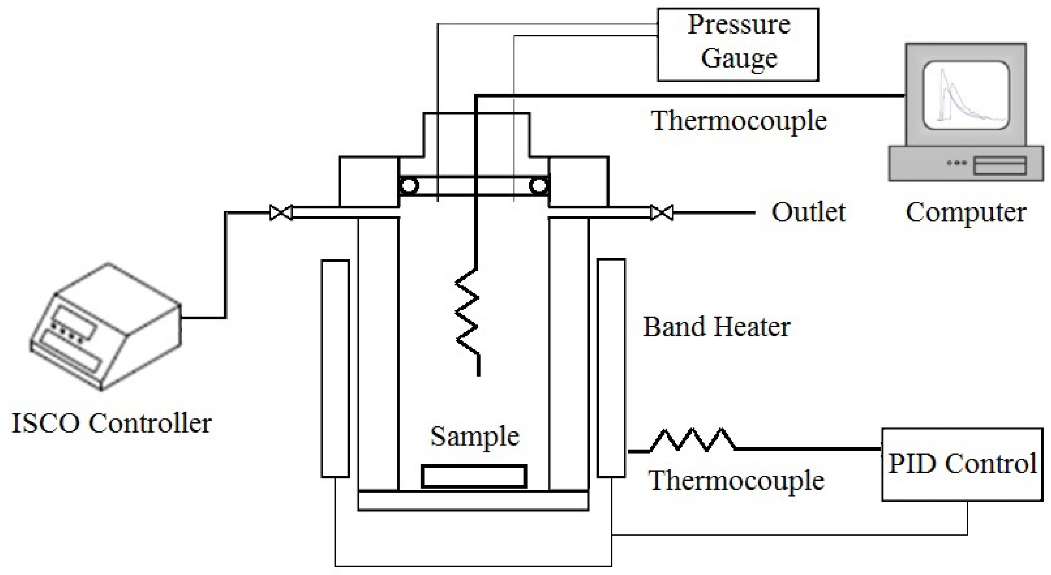
A first step in the CBA propellant characterization was that of obtaining an empirical correlation between the CBA mass and the corresponding adiabatic decomposition temperature. Experiments were thus performed in a high-pressure vessel apparatus (Parr Instruments, Moline, IL, USA) with a volume of 25 mL volume. The vessel configuration is that of a cylinder and a band heater, with the latter connected to a PID controller to increase temperature gradually. Masses between
and
g of the chemical blowing agent were enclosed inside the vessel and heated up at a constant rate of 15
C per minute until the thermal decomposition was initiated; the heating rate used was based upon the heating element adapted to the test apparatus. Once initiated, the decomposition is self-sustaining and proceeds until completion. The experimental arrangement used is shown in
Figure 5.
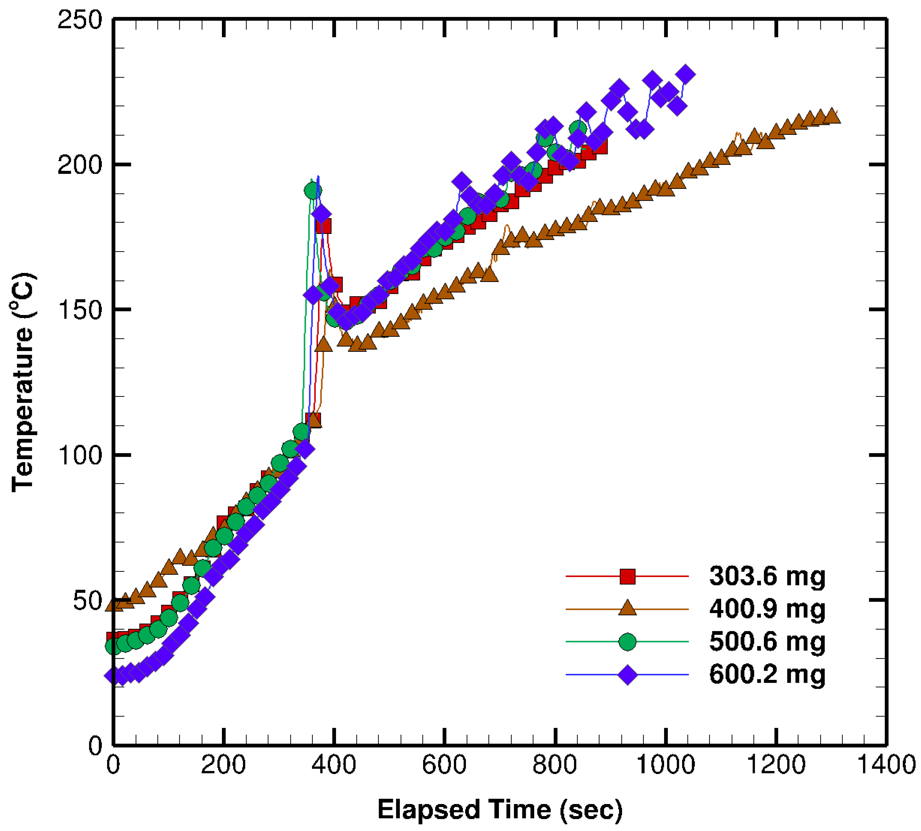
Figure 6 presents a collection of the temperature histories within the vessel corresponding to different masses of the CBA (azodicarbonamide). The reaction was observed to be exothermic as expected. When a critical temperature is reached, the vessel goes into rapid “thermal runaway” and the chemical reaction produces gas and heat, with the exothermic peak in the range of 98–119
C. For these experiments, one expects the decomposition temperature characteristics to be independent of the propellant mass. This is essentially what is observed, with any variability observed being attributed to the limitations of the testing apparatus and measurement capabilities. Further, the similarity in the trends shows the repeatability of the decomposition process. It is important to note that the extended amount of time required for the decomposition to occur is a direct result of the experimental test chamber used to conduct the testing. The test apparatus contained a small mass of propellant within a relatively large volume that was thermally insulated and the heating mechanism was not optimized for its performance.
According to data reported in the literature [
18], the range for the decomposition of pure azodicarbonamide initiates at a significantly higher temperature (∼190
C). This suggests that azodicarbonamide samples used in these experiments were mixed with other compounds to effectively reduce its decomposition temperature and presumably to improve the decomposition performance. Possible additives include metal salts, such as Pb, Zn, and Cd compounds, some of which are used as stabilizers. Therefore, the degree to which the decomposition temperature is reduced depends on which additive is chosen and the amount used [
19]. Furthermore, Sims et al. [
20] found that the decomposition temperature of chemical blowing agent systems based on azodicarbonamide strongly depends on the powder particle size and the imposed heating rate. This is especially noteworthy when considering possible deleterious impacts upon thrust production due to the presence of small particulates resulting from incomplete decomposition.
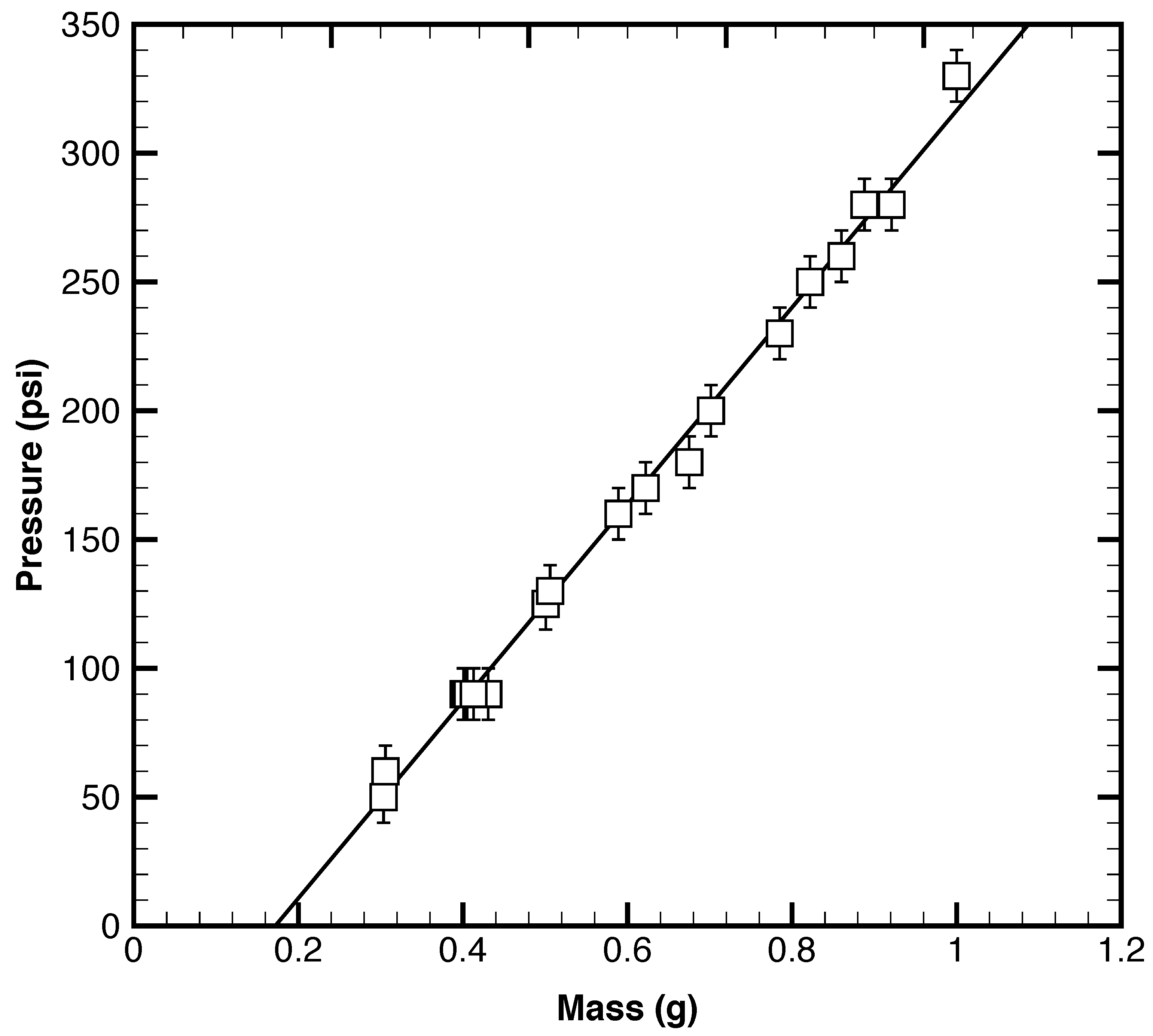
The corresponding measurements of the maximum decomposition pressure occurring in the vessel appear in
Figure 7. These data confirm a linear relationship between the peak pressure and the mass of CBA. A curious result that was persistent throughout all of the experiments, however, was the fact that the observed linear relation did not intercept through the origin. The experimental resolution of the apparatus prevented accurate measurements for masses below 0.3 g, and so it was impossible to resolve this question. Lastly, from the combined pressure and temperature profiles, it was observed that the peak exotherms at 98–119
C correspond approximately to the maximum rate of gas yield from the chemical decomposition process.
4.2. Test-Firing and Thrust Measurements
To quantify the thrust characteristics of the prototype, a specially designed test rig was constructed. The test rig consists of the thruster assembly mounted a 3D printed cart designed to operate on a linear air track. All experiments were performed with the nozzle exit at ambient pressure. A DC power supply (5 A and 3.5 V) was used to deliver current to the nichrome heating element via electrical contacts extending from the propellant chamber. This power level was chosen to produce the fastest possible heating and decomposition of the propellant. A photograph of the testing apparatus prior to firing appears in
Figure 8. During an experiment, electrical contact is made and the nichrome elements rapidly heats up and decomposes the CBA, thus pressurizing the chamber. At the maximum designed chamber pressure, the rupture disc fails and thrust is produced, thereby accelerating the test rig on the linear air track. The finite duration of the thrust production as the chamber depressurizes corresponds to a total impulse (or impulse bit) for the firing.
Experiments were recorded using a high-speed CCD camera to analyze the position of the test rig on the air track as a function of time. From this data, the velocity and acceleration of the cart were obtained and used to determine instantaneous thrust production. Thrust profiles appear in
Figure 9 for different rupture disc thicknesses (i.e., burst pressures). Each dataset shown represents the ensemble average over four trials. At
s, the nichrome igniter is energized and the CBA is heated until the decomposition process is initiated. In the testing, there was a lag observed between the igniter activation and the generation of thrust. This lag was typically on the order of 1–2 s, depending on the level of the burst pressure and the efficiency of the heater/CBA packaging. In all cases, the thrust rapidly reaches a peak value and then decays. The peak value of the thrust occurs repeatably at
s for all burst pressures; however, the decay process is lengthier at higher burst pressures. Conservatively, the thrust production is completed within approximately 0.2 s in all cases, and much sooner at lower pressures. The presence of thrust oscillations that can become negative is also observed at the highest burst pressures (
Figure 9c,d). This curious result suggests the result of significant flow oscillations occurring within the microthruster including backflow at the exit. This phenomenon is further addressed in
Section 5.
The impulse bit delivered by the microthruster during its firing is a key parameter in characterizing the propulsion performance. From the terminal velocity of the test rig on the linear air track, the total impulse can be determined from the test rig’s change in momentum. The results are shown in
Figure 10. The error bars in the figure are based upon the variations in total impulse over four trials at each burst pressure (number of foil layers). It was found that a nearly linear relation exists between the impulse bit for this microthruster and the burst pressure, with a range of 4 mN·s (4 layers) to 15 mN·s (8 layers).
It is clear that the thrust levels observed experimentally are far below the estimated values in the preliminary design discussed in
Section 3. Although numerous simplifying assumptions were made in that analysis, this cannot account for magnitude of the discrepancy. It is clear that some phenomenon is present in the experimental system that was not accurately presented in the design model. To investigate this further, it was deemed appropriate to examine the internal unsteady flow dynamics using numerical simulations.
5. Numerical Simulations of Transient Nozzle Flow
A Computational Fluid Dynamics (CFD) model was constructed to investigate the transient flow structure resulting from disk rupture and the effects on thruster performance. The explicit, finite volume, compressible flow solver rhoCentralFoam [
21], part of the OpenFOAM v4.1 CFD suite, was used to conduct fully-transient laminar simulations. The central upwind scheme of Kurganov et al. [
22] was used with van Leer-limiting [
23].
The computational domain was developed based on the prototype geometry and consists of the plenum, converging-diverging nozzle, and a region downstream that extend 10 times the nozzle exit diameter in the axial and transverse directions. Symmetry is leveraged to reduce the computational expenditure by simulating a wedge of the full axisymmetric nozzle. To model the effect of the rupture disc, mesh elements upstream of the disc are initialized at the rupture pressure of the disc ( kPa) and the decomposition temperature of the propellant ( K), while elements downstream are initialized at ambient conditions ( kPa and K). As a result, a discontinuity (shock) lies between these two regions initially. The blowing agent is assumed to be completely decomposed and the effects of solid residue are not considered. The plenum and nozzle walls are treated as no-slip and adiabatic. A far-field pressure relaxed condition is imposed at the outlet of the extend downstream region with kPa and K.
The computational mesh was generated using Pointwise® grid generation software. The final static mesh consisted of four structured domains with a total of ≈125,000 cells. Octree style dynamic mesh refinement based on the magnitude of the density gradient is implemented for better resolution of the transient shock structure. A value of kg/m is used as a threshold for cell splitting (refinement) and a value of kg/m is used for recombination of split cells (coarsening). Cells are allowed to be subdivided a maximum of two times producing sub-cells per original cell in refinement regions. The number of cells in the dynamically refined mesh varied throughout the course of the simulation and primary stayed within the range of 400,000–1,000,000 total cells. Good agreement was found between the time-dependent thrust and mass flow rate estimated by the dynamically refined mesh and static mesh indicating the achievement of grid independence.
Performance results from the transient simulation are presented in
Figure 11 with the instantaneous mass-flow rate and thrust plotted in
Figure 11a,b, respectively. The mass flow is assessed at the nozzle exit plane according to
and the thrust is assessed by applying
to the nozzle and plenum walls. During the firing, it is observed that the nozzle experiences periods of both outflow and backflow with corresponding periods of positive and negative thrust. This is consistent with the experimental observations in
Figure 9. Plots of the cumulative mass flow exiting the thruster and the total impulse delivered appear in
Figure 11c,d.
The oscillatory thrust and mass flow appears to be caused by acoustic resonance in the plenum and converging portion of the nozzle. When the rupture disc breaks, a shock front forms and propagates into the converging portion of the nozzle. The shock then interacts with the converging side-walls and eventually the steep density gradient at the nozzle throat. When the original shock front is reflected off the nozzle throat, it creates a region of rarefaction upstream of the throat. The rarefaction region breaks the choked condition and subsequently draws flow back into the nozzle. Pseudo-Schlieren contours and the axial velocity component are plotted for
ms, the first spike in thrust/mass-flow, and
ms the first trough in thrust/mass-flow in
Figure 12. From the Schlieren contours, the complex structure of the flow is evident. At
ms, there are oblique shocks and a Mach-disc forming inside the nozzle, characteristic of the over-expanded condition of the test-firing. A strong shock can also be seen in converging nozzle section. At
ms, the shock structure in the expander is replaced by vortical inflow.
Additional simulations were performed to investigate whether the resonant behavior could be mitigated by moving the rupture disc to the throat from its original upstream position; all other conditions were held constant. The pressure distributions used to initialize the two simulation cases are shown in
Figure 13a. A snapshot of the instantaneous velocity field depicting the resultant flow structure of the two rupture disc locations is shown in
Figure 13b. When the rupture disk located at the throat a coherent jet structure forms while in the case of the original configuration it does not.
Thrust and impulse profiles for two rupture disc locations were computed and are featured in
Figure 14. Simulation results suggest that relocating the rupture disc to the throat yields a smaller amplitude thrust profile but a larger total impulse. This appears to be caused by two phenomena working in tandem. By moving the rupture disc to the throat, the original shock exits out the expander instead of reflecting around the plenum and converging portion of the nozzle. This reduces plenum pressure oscillations and makes the nozzle behavior closer to quasi-stead-state. Moreover, placing the rupture disc at the throat give the nozzle a larger high-pressure reservoir allowing for a longer burn at higher pressures. Together, these two effects yield a smoother thrust profile and larger total impulse.
6. Discussion
This study has demonstrated the viability of a chemical blowing agent as a propellant in a meso-scale prototype thruster, yet it is clear that the system will require further refinement to be efficacious for use in small satellites. The primary challenges lie in: (1) the reduction in size; and (2) the corresponding ignition method, with the latter being manual at present.
In terms of scale reduction, at small scales, it is expected that heat loss through the chamber walls will emerge as a concern for the ignition and decomposition of the propellant. The increased surface area to volume ratio that comes with the small size of the miniaturization can cause chemical and thermal quenching [
24,
25]. This aspect is further compounded by the relatively slow decomposition process for a blowing agent propellant in comparison to more energetic solid propellants. The increased heat loss has the potential to inhibit or stifle the chemical decomposition, thus negating control over the reaction. The outcome could be a non-sustainable or unstable reaction process leading to non-reproducible results. It is clear that thermal insulation of the reaction chamber will be a key consideration in the scaling down of this design. Future approaches include low thermal conductivity materials such as Foturan (photosensitive glass) as a potential solution in order to minimize the thermal cross-talk between neighboring cells.
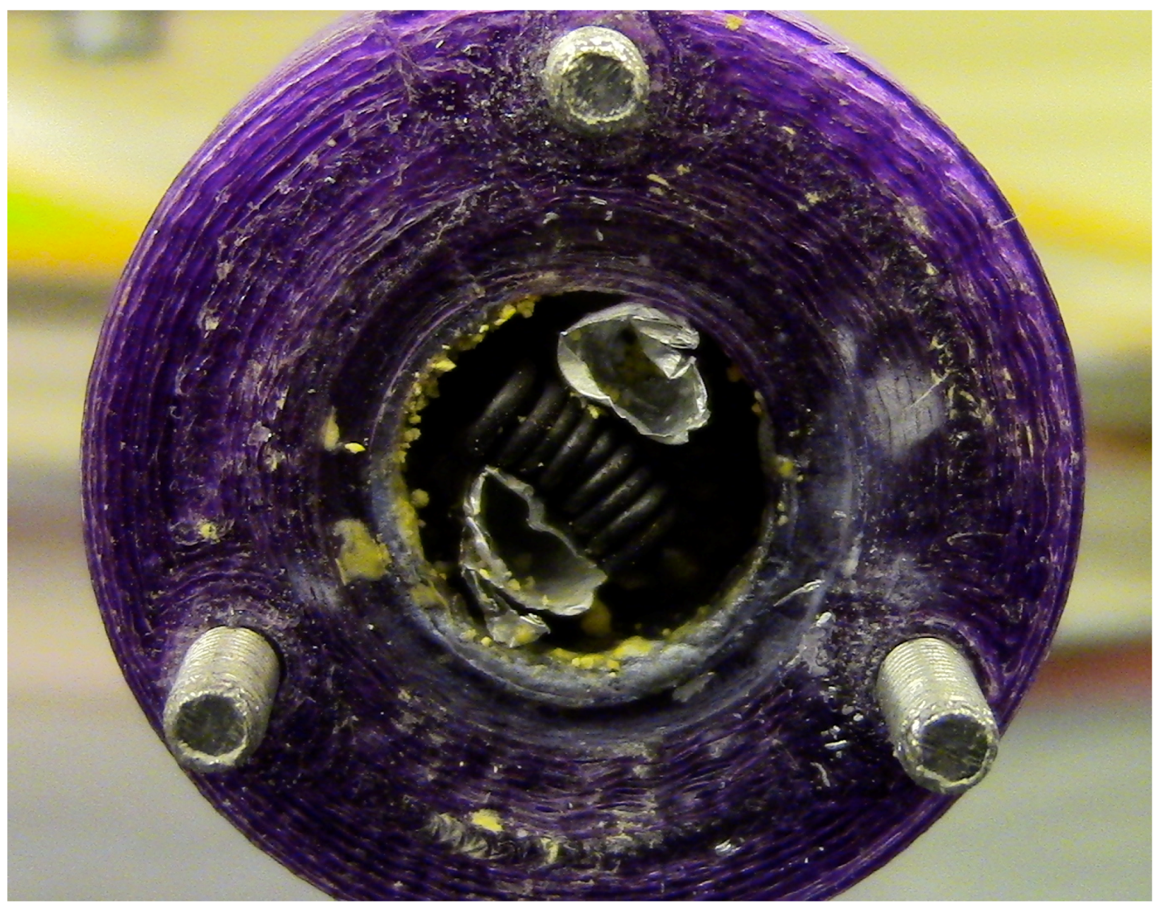
The ignition system, in contrast, will likely benefit from the miniaturization of the geometry. With the unique capabilities available in MEMS-manufacturing, it will be possible to better integrate the ignition heater with the blowing agent in the packaging. Examination of the propellant chamber of the current meso-scale prototype has revealed that the current heater/CBA packaging results in unreacted propellant after firing. An illustration of this is shown in
Figure 15. With miniaturization, the increase in contact area between the propellant and the heater will make for a more consistent and repeatable ignition process that should also be faster. Successfully tested micro-igniter designs such as polysilicon resistors can be found in the literature [
26,
27].
A third and final area for the improvement lies in the re-design of the chamber and nozzle geometry based upon the specific and transient nature of the flow in this device. The numerical simulations have shown complex transient shock patterns can form in devices that use a rupture disc. Further, the simulations suggest that the shocks can interact with the nozzle geometry in such a way as to produce a periodic loss of the choked condition at the throat. Without choking present, supersonic flow conditions cannot be achieved and thus the traditional de Laval nozzle design becomes inappropriate. To remedy this, future directions include moving the rupture disc to the throat from the original upstream position and a new design of decomposition chambers with different volumes and/or geometries to promote flow choking. If this proves unworkable, a redesign or complete elimination of the nozzle may be necessary.
7. Conclusions
In this paper, we describe the developmental efforts towards a new miniaturized thruster propulsion concept capable of delivering the low levels of thrust and impulse necessary for attitude and control adjustments inherent to small satellite formation flying. The propulsion system uses the thermally-driven decomposition of a chemical blowing agent as a propellant. The use of the chemical blowing agent is well-suited for small satellite operations, especially CubeSat platforms, where current launch payload restrictions place constraints on storage tank pressurization, amount of stored chemical energy, and toxicity of the propellant.
A meso-scale proof-of-concept thruster using the CBA azodicarbonamide as a propellant was designed and constructed. Experimental testing demonstrated the viability of the concept, but showed that the performance levels were well below those estimated during the design stage. Subsequent numerical simulations of the gas dynamic flow in the device during firing indicated acoustic resonant phenomena in the converging nozzle and plenum attributed to the degradation of performance relative to the idealized steady-state case. The simulations also suggested that substantial performance gains might be achieved by properly designing the converging nozzle section and plenum to attenuate the strong shock that occurs during burst disc rupture.
The transition to a micro-scale device is expected to offer improved performance based primarily on more efficient heating and decomposition of the CBA. Aside from lower power input at the smaller scale, more efficient coupling of the heating element and the CBA is possible; coupled with the greatly reduced thermal mass (volume), much faster activation times are anticipated. Furthermore, studies have shown that the decomposition reaction occurs much more rapidly under pressure. On the micro-scale, it is easier to fabricate a stronger rupture disc than for the meso-scale design. The combination of reduced volume and stronger rupture disc will naturally lead to elevated pressures and improved performance.
Overall, the outcomes of this study indicate that the concept merits continued development. Particular emphases moving forward lie in the reduction of the device size, the ignition/propellant packaging system, and redesign of the plenum and nozzle geometry to improve the transient flow characteristics.


 ,
, 


