Article

Fabrication and Testing of the Cold Gas Propulsion System Flight Unit for the Adelis-SAMSON Nano-Satellites

1
Rafael—Advanced Defense Systems, Haifa 3102102, Israel
2
Asher Space Research Institute (ASRI), Technion—Israel Institute of Technology, Haifa 320003, Israel
*
Author to whom correspondence should be addressed.
Aerospace 2019, 6(8), 91; https://doi.org/10.3390/aerospace6080091
Submission received: 27 June 2019 / Revised: 5 August 2019 / Accepted: 13 August 2019 / Published: 19 August 2019

Abstract

:
Adelis-SAMSON is a nano-satellite mission aimed at performing geo-location of target signals on Earth using a tight three-satellite formation in space. To maintain formation, each nano-satellite is equipped with a cold gas propulsion system. The design, qualification, and integration of the Adelis-SAMSON nano-satellite propulsion system is presented in this paper. The cold gas propulsion system mass is approximately 2 kg, takes a volume of 2U, and generates a thrust of 80 mN from four thrusters using krypton as a propellant. We first present the propulsion system requirements and corresponding system configuration conceived to meet the mission requirements. Subsequently, we present the system architecture while listing all the components. We overview the particular role and qualification process of four of the propulsion system’s components: the propellant tank, thruster assembly, pressure regulators, and fill and vent valve. We detail the tests performed on each component, such as proof pressure tests, vibration tests, and external leak tests. Finally, we present the propulsion system level tests before delivery for satellite integration and discuss the propulsion system’s concept of operations.

1. Introduction

In recent years, nano-satellite missions consisting of spacecraft with a launch mass of less than 50 kg have seen a rapid growth from less than 20 nano-satellites launched in 2010 to over 200 launched in 2018 [1]. These satellites are used for a variety of applications, e.g., Earth observation missions, communications services, and interplanetary research [2]. Of the different existing nano-satellites, cubesats are the most common of the configurations used. Cubesats are nano-satellites constructed of basic 10 × 10 × 10 cm3 units, also denoted “U”. Due to their small size and modular structure, cubesats are cost-effective and easily integrated compared to conventional satellites weighing hundreds or several thousands of kilograms. For this reason, numerous universities and academic institutes have executed cubesat missions where the cubesat was manufactured and integrated in-house by the academic institutes. Nonetheless, because the cubesat market is still young in terms of the commercial space market, cubesat technologies are immature in comparison with the traditional satellite technologies. This poses technological challenges to the academic institutes and industries that in many cases have to develop their own subsystems tailored for cubesats.

1.1. The Adelis-SAMSON Project

The Space Autonomous Mission for Swarming and geOlocation with Nano-satellites (SAMSON) project is an academic endeavor aimed at testing new algorithms for cluster-keeping and geolocation by using three-nano-satellite clusters in Low Earth Orbit (LEO). The project, led by the Asher Space Research Institute (ASRI) at the Technion, includes the design, development, integration, and mission execution of all three nano-satellites and algorithms [3]. Each of the three nano-satellites is a 6U CubeSat with a target nominal launch mass of less than 8 kg. The satellites are planned to be launched in late 2019 and the mission duration is to be at least 12 months.
To perform cluster-keeping and orbit maneuvers, each of the three nano-satellites requires some means of propulsion [4]. Therefore, it was decided to incorporate a propulsion module aboard each of the three cubesats. The propulsion system design, development, manufacturing, and qualification were assigned to Rafael for its expertise and experience in space propulsion systems. Due to each satellite’s low mass (<10 kg) and small volume (6U), its propulsion system must be compact and light-weight. At the same time, to maintain the three satellites in accurate formation and orbit, sufficient maneuverability is required (∆V = 20 m s−1).

1.2. Propulsion System Requirements

To accommodate mission maneuverability, a set of requirements was formed for the propulsion system. The formulated propulsion system requirements are listed in Table 1.
Because the Adelis-SAMSON project is principally an academic endeavor where the initial design phases were performed by students, propulsion system simplicity and a safe propellant were key guidelines. The propulsion system designers were encouraged to adopt a cubesat propulsion system technology with a simple interface for the satellite, minimum components, and an inert propellant.
In this paper, we present the design, manufacturing, integration, and testing phases of the Adelis-SAMSON propulsion system. First, we overview the propulsion system layout and architecture by listing its main features and components. Additionally, we explain the propulsion system’s operation logic and discuss its limitations. Subsequently, we detail each component’s functionality and emphasize its qualification process. Lastly, we discuss the propulsion system’s concept of operations during its intended mission.

2. Propulsion System Design and Architecture

2.1. Propulsion Technology and Conceptual Design

The propulsion system technology chosen for the Adelis-SAMSON cubesats is cold gas propulsion. Cold gas was chosen because of its simplicity, lean interface to the satellite, low power requirement, and its ability to incorporate a variety of inert propellants. Cold gas propulsion technology relies on gas expansion through a nozzle to generate thrust. The propellant is allowed to flow from a propellant storage tank to a converging/diverging nozzle out of which it expands to open space [5]. Conventional cold gas propulsion systems can be designed to generate thrust levels of tens of millinewtons to tens of Newton. In addition, cold gas propulsion systems are characterized by low specific impulse, relative to chemical or electric propulsion systems, of tens to a few hundred seconds, depending on the propellant atomic mass. In addition to its attributes, cold gas propulsion technology has a well-established space operation heritage. This technology has been successfully used in the past in dozens of satellites, from full-size satellites (>100 kg) [6] to cubesats [7]. This technology is well documented and no major knowledge gaps exist in its development and utilization. Specifically, at Rafael, cold gas propulsion systems have been developed, produced, and operated in space [8].
The conceptual design phase of the Adelis-SAMSON cold gas propulsion system is detailed in Reference [9]. Essentially, to meet the stringent propulsion system volume requirements, the system utilizes a titanium cylindrical propellant tank and krypton as its propellant. Krypton propellant was chosen after a meticulous analysis in which a variety of propellants were examined. Krypton was found to be most suitable due to its density, which allows for the compression and storage of the required calculated mass of 628 gr. This propellant mass was calculated during the initial stages under stringent propellant contingency requirements. These propellant contingency requirements were removed during the propulsion system’s final design phase, leading to a lower required propellant mass, as described hereafter. Krypton is also an inert gas that poses no safety risks to the integration team or the Adelis-SAMSON satellites.
In the conceptual design phase, several system configurations (all variations of cold/warm gas propulsion technologies) were examined. Specifically, the benefit of adding a propellant heating capability, thus enhancing the propulsion system’s performance, was analyzed [10]. It was eventually decided to omit the heating capability in order to reduce system complexity and minimize electrical power consumption. Reference [9] details the propulsion system alternatives and the reasoning for the chosen configuration.
The propulsion system schematic is presented in Figure 1. The propulsion system consists of the propellant tank, filter, high pressure latch valve, pressure regulators, and a four-branch manifold that feeds into four thruster assemblies. Each thruster assembly includes one solenoid valve and a nozzle through which the propellant is released. In addition to the components listed above, the propulsion system also includes a high pressure transducer, a low pressure transducer, and a fill and vent valve for propellant loading.

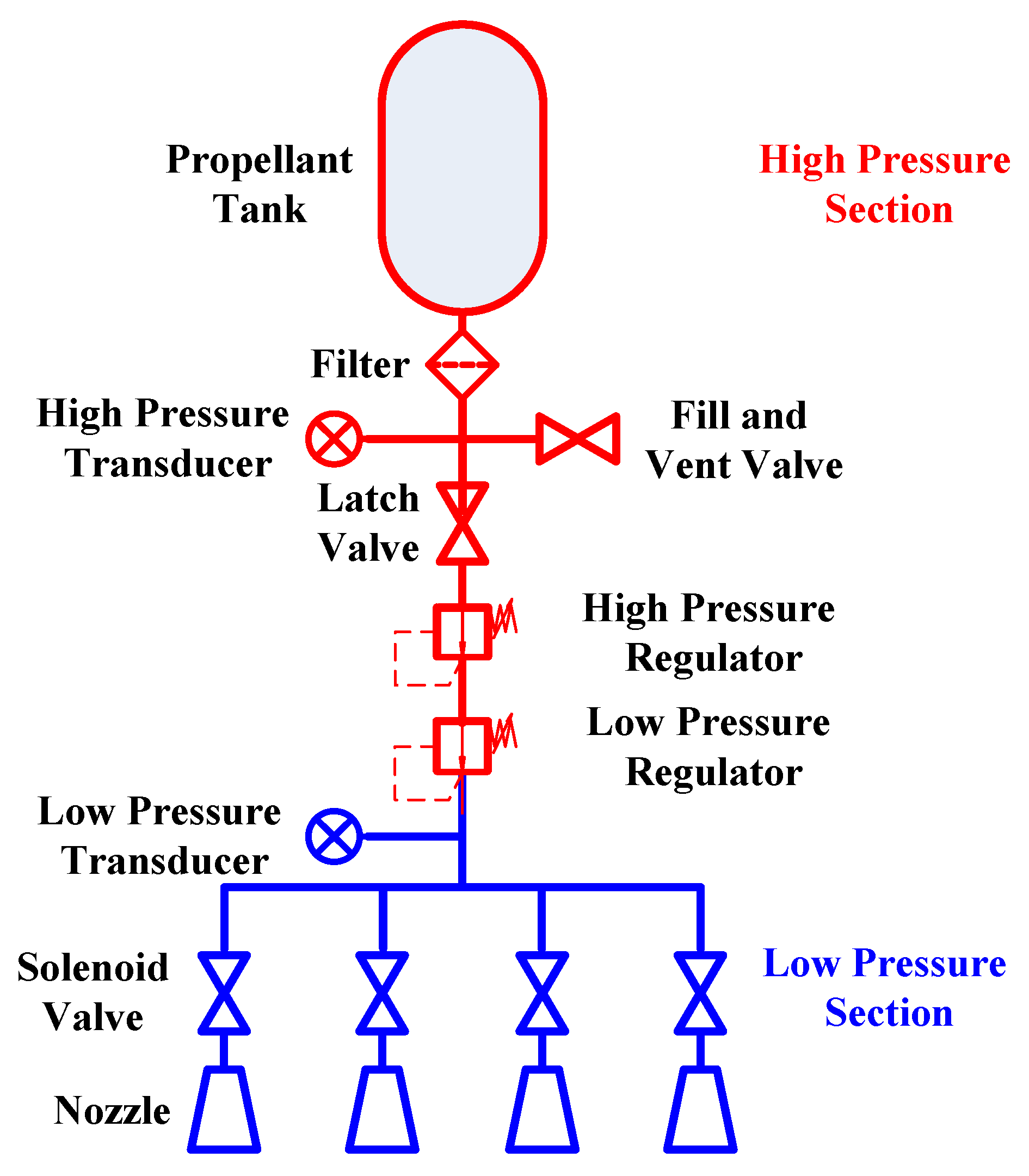
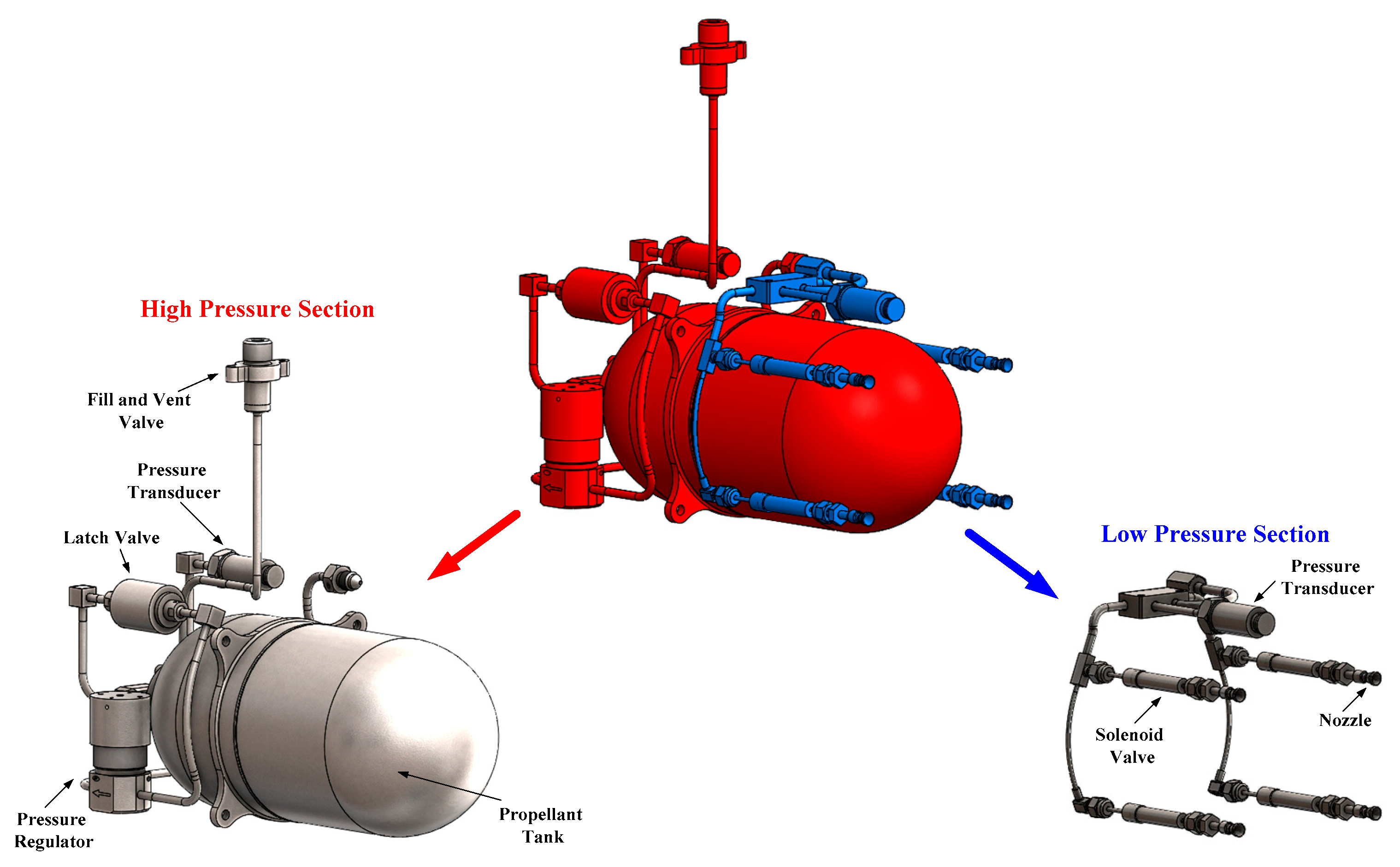
2.2. Propulsion System Architecture

The Adelis-SAMSON propulsion system architecture follows the design presented in Figure 1. A photograph of the integrated propulsion system and illustration of the propulsion system location inside the satellite are presented in Figure 2. It can be seen from the figure that the integrated propulsion system fits the 2U allocated volume where the propellant tank takes the majority of the volume. A fill and vent valve, extending from the propellant tank, is located on the external satellite face to allow for propellant loading, which is performed after propulsion system integration into the Adelis-SAMSON satellites. The propulsion system is integrated into the Adelis-SAMSON nano-satellites via dedicated structure frames to which all system components are bolted. Four thruster nozzles are located on the external face of the propulsion system (left-most face in Figure 2).
The high and low pressure sections of the propulsion system are illustrated in Figure 3. All components of the high pressure section (apart from the propellant tank exit) are welded to assure leak-tight connections, whereas the components on the low pressure section are welded, brazed, or connected via standard screw fittings. The maximum expected krypton gas pressure of the high pressure section is 160 bar and the maximum expected pressure of the low pressure section is 2 bar.
All system components were either procured or manufactured at Rafael. Apart from the latch valve, all of the system components were qualified at Rafael and propulsion system integration was conducted at Rafael. Table 2 lists the propulsion system components, mass of each component, and name of the supplier. The qualification methodology and guidelines follow NASA’s general environmental standards [12].
Overall, the system wet mass is 1961 gr, of which the krypton propellant accounts for 468 gr.

3. Propellant Tank

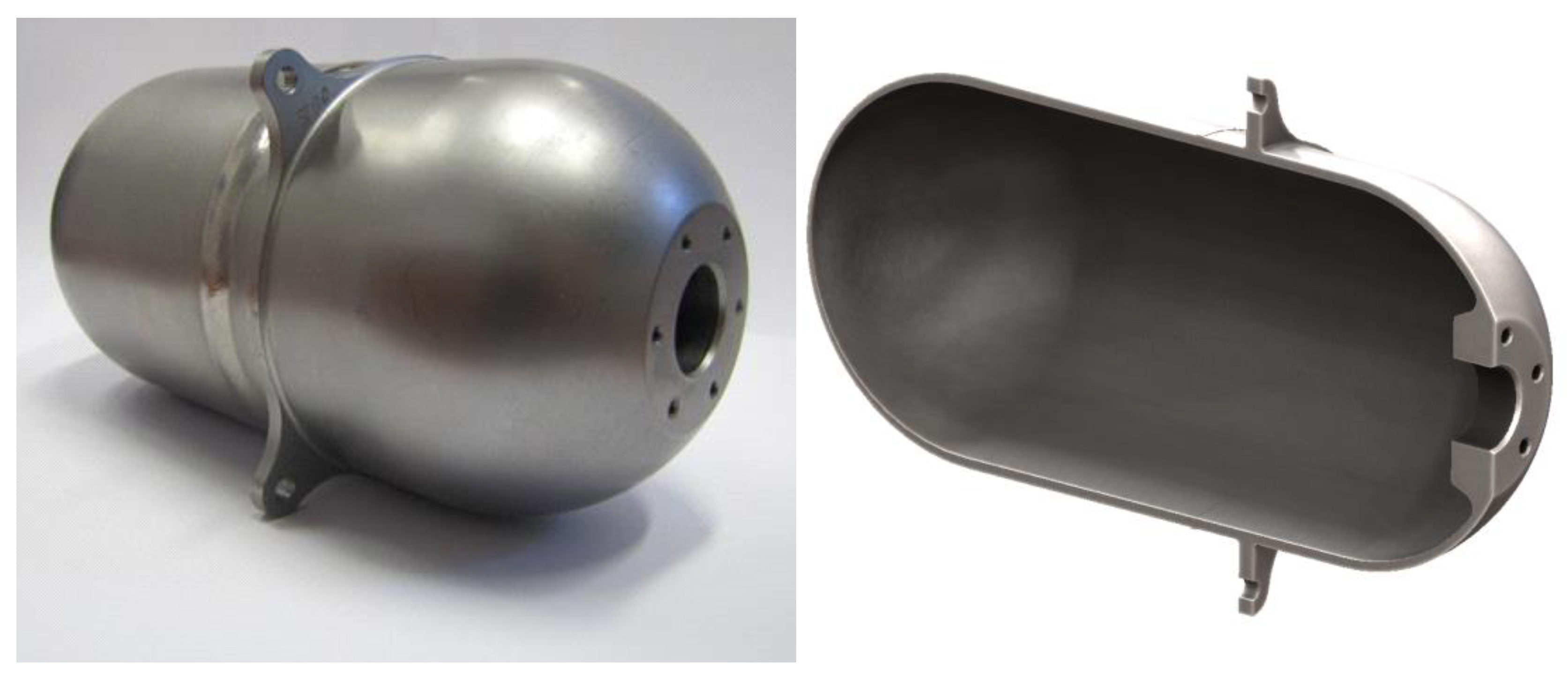
3.1. Propellant Tank Description

The propellant tank is the component responsible for propellant storage. The propellant tank designed for the Adelis-SAMSON nano-satellites is a capsule-shaped container made of Ti-6Al-4V titanium alloy, dedicated to store propellants at the Maximum Expected Operating Pressure (MEOP) of 160 bar. The propellant tank is presented in Figure 4 and its properties are listed in Table 3.
For the Adelis-SAMSON nano-satellites, 468 gr of krypton are compressed into the tank and stored at temperatures no higher than 30 °C, according to the defined propulsion system’s temperature envelope (Table 1). Because the propellant tank is the largest component of the propulsion system, optimizing its shape to the available volume was critical. A capsule-shaped geometry was selected to best fit the propellant tank alongside the other propulsion system components given the allocated propulsion system volume.
The propellant tank was constructed using two welded sections. Each section was machined, cleaned, and inspected prior to the welding procedure. The tank was connected to the propulsion system via a leak-tight screwed connection.
A total of five identical propellant tanks were manufactured, of which three were ultimately supplied for the three nano-satellites; the two other propellant tanks were used for a dedicated qualification process.

3.2. Propellant Tank Tests and Qualification

The propellant tank qualification and test campaign is according to US military standards for the safe design and operation of pressurized space systems (MIL-STD-1522A [13]). The standard defines the required pressure factors for each acceptance test, determines possible failure modes, and lists the acceptance tests required. Each of the five propellant tanks were subject to a set of acceptance tests (Figure 5) which included: (a) visual inspection; (b) mass and volumetric measurement; (c) proof pressure test at 1.5×MEOP; (d) external leakage test; (e) cleanliness and dryness verification; and (f) final inspection. All the tests assured that each one of the propellant tanks to be supplied meets all the functional requirements.
Following the acceptance tests on all five propellant tanks, one was randomly selected for an actual burst pressure test. The chosen propellant tank was pressurized until an actual tank burst was achieved at 3.6×MEOP (576 bar), which is significantly higher than the required burst pressure of 2×MEOP (320 bar). The measured actual burst pressure is in line with a structural simulation of the propellant tank that indicated approximately the same burst pressure.
Following the actual burst pressure test, one of the remaining four propellant tanks was randomly selected and sent to a full set of 10 qualification activities (Figure 6). These are: (a) pressure cycling test where a total of 62 loading-venting pressure cycles are applied; (b) external leakage test; (c) vibration test to emulate launch loads; (d) visual inspection; (e) post-vibration leakage test; (f) proof pressure test at 1.5×MEOP (240 bar); (g) mass and volumetric measurements; (h) X-ray Non-Destructive Test (NDT) to verify no cracks were formed during all previous tests; (i) required burst pressure test at 2×MEOP (320 bar); and (j) final visual inspection.
The pressure cycling test emulates 50 loading–venting cycles at a pressure of 1×MEOP (160 bar) and an additional 12 loading–venting cycles at a pressure of 1.5×MEOP (240 bar) (see Figure 7a). During each cycle, the propellant tank was pressurized for the duration of five minutes after which the pressure was relieved and the process immediately re-initiated. Because the pressure cycling test inflicts strains on the propellant tank, an external leakage test was performed after this test.
The vibration test, performed on a shaker, mimics the acceleration forces exerted on the propellant tank during satellite launch. Specifically, sinusoidal and random vibration conditions were exerted on the propellant tank. The propellant tank was fixed to the shaker while dedicated accelerometers measured the actual forces sensed by the propellant tank in all three axes. The propellant tank was mounted directly onto the shaker using its four mechanical interface points. Modal simulation and later frequency sweeps on the shaker showed that the lowest resonant frequency of the tank is approximately 1000 Hz, which is much higher than the minimum required 100 Hz [14]. Thus, there is no concern for vibration enhancement via tank mounting on the satellite structure. During all the vibration tests, the propellant tank was pressurized to MEOP of 160 bar. The applied vibration levels are presented in Figure 8.
The thermal cycling test, performed after the vibration test, appraises propellant tank resilience to extreme temperatures outside the required temperature envelope, thereby assuring the thermal robustness of the propellant tank design. A total of eight thermal cycles between −12 °C and 70 °C were applied over the course of 80 h (see Figure 7b). At the start of the thermal cycling test, the propellant tank was pressurized to the MEOP of 160 bar. Following the cycling and vibration tests, a set of tests was conducted to verify that no damage was inflicted on the propellant tank and to validate its functional robustness.
The propellant tank qualification procedure was concluded with a required burst pressure test at 2×MEOP (320 bar), at which the propellant tank did not burst, as expected. The final burst test results align with the actual burst pressure test performed on an identical propellant tank as described above. The propellant tank successfully passed the vibration tests with no visible damage or performance degradation. This qualifies the propellant tank for its designated mission aboard the Adelis-SAMSON nano-satellites.
The three remaining propellant tanks, all of which successfully passed the described acceptance tests, were integrated into the three Adelis-SAMSON propulsion systems. The fourth propellant tank, which passed the qualification procedure, was stored as a backup.
Any pressurized vessel aboard a spacecraft needs to be approved by the launch provider prior to satellite delivery. Thus, all qualification information was presented to the launch provider. After a review process of the qualification campaign presented here, the propellant tank was approved for launch.

4. Thruster Assembly

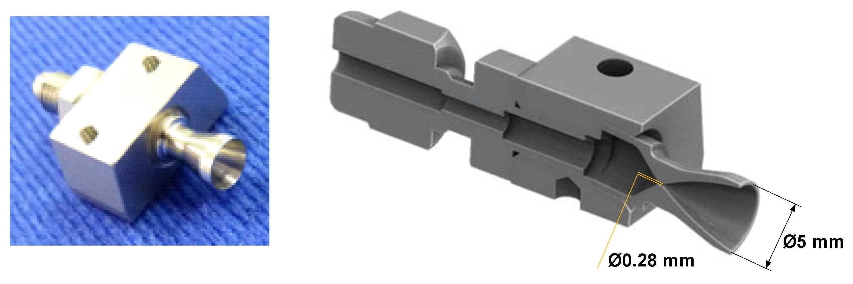
4.1. Thruster Assembly Design Description

Each Adelis-SAMSON nano-satellite incorporates four identical thruster assemblies. These assemblies are responsible for thrust generation via gas expansion through a diverging nozzle. Each thruster assembly consists of a normally closed solenoid valve, which is connected to a stainless steel diverging nozzle.
The nozzle has a throat diameter of 0.28 mm and an exit diameter of 5 mm (see Figure 9). Therefore, the nozzle expansion ratio (Ae/At) is 319. The nozzle dimensions were chosen according to manufacturing constraints and required thrust given the input pressure of 2 bar at the nozzle inlet. Specifically, the nozzle throat diameter is subject to manufacturing capabilities while the nozzle expansion ratio (Ae/At) was determined to meet the thrust requirement of 20 mN per thruster. Using Equations (1) and (2) for adiabatic gas expansion through a nozzle [15], the pressure ratio (pc/pe) and thrust (F) can be calculated.
A e A t = { ( γ 1 2 ) ( 2 γ + 1 ) ( γ + 1 ) ( γ 1 ) ( p e p c ) 2 γ [ 1 ( p e p c ) ( γ 1 ) γ ] } 1 2
where γ is the specific gas ratio, which is 1.66 in the case of krypton, and Pe/Pc is the pressure expansion ratio, and
F = { { ( 2 γ 2 γ 1 ) ( 2 γ + 1 ) ( γ + 1 ) ( γ 1 ) [ 1 ( p e p c ) ( γ 1 ) γ ] } 1 2 + p e A e p c A t p a A e p c A t } A t p c
where F is the thrust produced by one thruster.
Equations (1) and (2) yield the projected thrust of 20.2 mN, which meets the mission thrust requirement per thruster.
It should be noted that in sub-millimeter throat diameters, boundary layer effects may affect the bulk flow and dissipative effects may be of concern [16,17]. However, for krypton at temperatures of 10–30 °C and a pressure of 2 bar, the Reynolds number at the throat is estimated at approximately 5000. At this value, the boundary layer may influence the bulk flow and reduce the effective thrust by up to 15% [16]. This risk of thrust reduction is acceptable for the Adelis-SAMSON mission.
A full explanation for the nozzle design reasoning and process is laid out in Reference [10].
The assembly was fixed to the satellite structure using two screws. All the thruster assemblies were aligned with the satellite’s Xb axis (opposite to the Xb axis direction) with an offset of 5 degrees relative to the Xb–Zb plane (see Figure 10). The reason for the thruster positioning offset is discussed in subsequent sections. To minimize errors in the assembly process, the nozzles’ structural adapters were manufactured with the required angular offset.
Thruster operation, thus the propulsion system operation, was performed by opening the solenoid valves to let the propellant eject through the thruster nozzle. All four valves were controlled directly by the on-board computer. Each solenoid valve was opened by receiving an initial voltage signal of 12 V for the duration of 2 milliseconds, followed by a “holding” voltage of 1.6 V at a power of 0.5 W [18]. As long as the holding voltage is maintained, the solenoid valve is open and thrust is generated. At the end of the required thruster operation, the applied voltage is halted and the solenoid valve automatically closes to stop thruster operation. Valve opening/closing latency is estimated at approximately 1 millisecond, thus allowing for thruster operation durations below 0.1 s if needed.
A total of 16 thruster assemblies were produced: 12 assemblies for the three nano-satellites to be flown and four assemblies for a backup propulsion system.

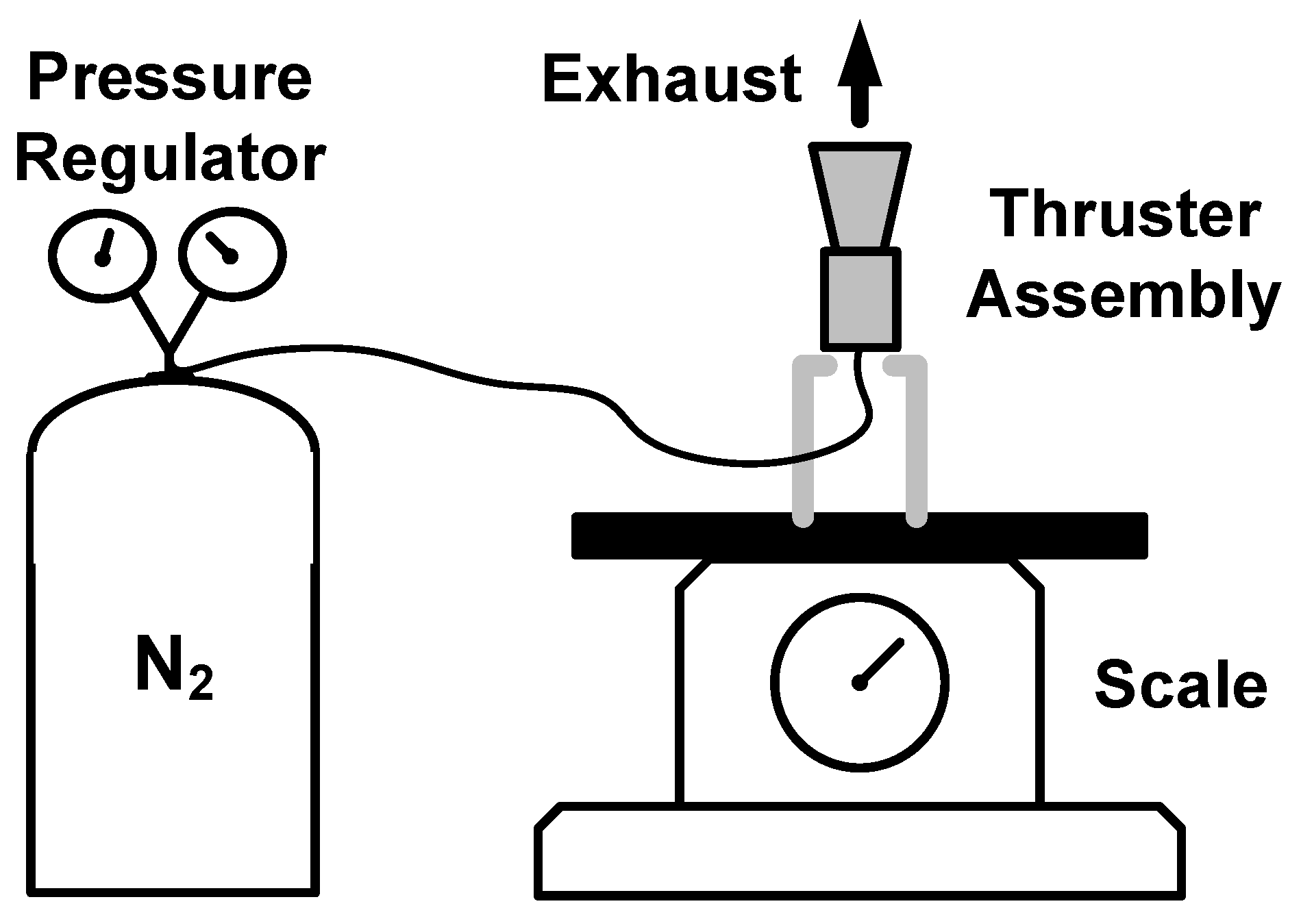
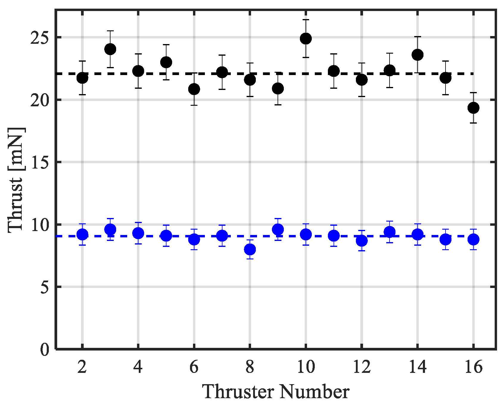
4.2. Thruster Design Validation

To validate thruster assembly performance, each thruster was laboratory-tested. Each thruster was positioned on a mass scale, its inlet tube was connected to an inlet pressure regulator, and it was operated in ambient air. To minimize the experiment cost, nitrogen gas was used instead of krypton. A schematic of the experimental setup is presented in Figure 11. Because flow separation is expected at ambient air conditions, each thruster operation was conducted at two different inlet pressure levels: 30 psig and 60 psig (3.07 bara and 5.13 bara, respectively). The thrust measured at the higher inlet pressure level (60 psig) was used to assess the nozzle’s flow separation factor while the thrust measured with the lower inlet pressure (30 psig) level was used to validate the thrust requirement.
Measured thrust results for both inlet pressure cases for each one of the 16 thruster assemblies are presented in Figure 12. For the 60 psig case, two measurements were performed with each thruster assembly. The average thrust levels at inlet pressures of 60 psig and 30 psig are 22.08 mN and 9.06 mN, respectively.
To account for measurement errors, several sources of errors were considered, e.g., thruster positioning accuracy, mass scale accuracy, and variations in inlet pressure.
To assess the effect of flow separation, the thruster exit plane pressure to ambient pressure (pe/pa) was computed. To do this, thrust was plotted as a function of the respective pressure ratio for the higher inlet pressure case (pc = 60 psig) according to Equation (2). For the examined case where thrust of 22.08 mN was measured, flow separation occurs at pe/pa = 0.125 (see Figure 13).
By employing Equations (1) and (2) and assuming the same flow separation ratio (pe/pa) of 0.125 for the low inlet pressure case (30 psig), the measured thrust of 9.06 mN can be corrected for krypton at zero ambient pressure and with an inlet pressure of 43.5 psig (2 bar). The corrected thrust is approximately 20 mN as required.
It should be noted that the thrust requirement of 20 mN was not validated by operating the thruster assemblies at the same conditions as expected in space, i.e., krypton propellant, zero ambient pressure, and inlet pressure of 43.5 psig (2 bar). The thrust requirement was validated indirectly by measuring thrust at different conditions and correcting the result for changes in operation conditions by employing Equations (1) and (2).

5. Pressure Regulator

Two pressure regulators separate the high- and low-pressure sections of the Adelis-SAMSON propulsion system. The pressure regulators were connected in series and reduced the pressure from the MEOP to the required pressure at the thruster nozzle inlet in two stages. The first pressure regulator reduces the pressure from a maximum of 160 bar to 10 bar, while the second pressure regulator reduces the pressure from 10 bar to 2 bar (see Figure 14). Both pressure regulators were manufactured at Rafael and weigh approximately 110 gr each.
After production, each of the pressure regulators were put through a short acceptance test (see Figure 15) that included a proof pressure test and an external leak test. For the proof pressure test, the regulator inlet was pressurized to 1.5×MEOP (240 bar). Additionally, a functional test was performed in which the outlet pressure of each of the pressure regulators was measured and the required outlet pressure was validated: 10 bar from the high-pressure regulator and 2 bar from the low-pressure regulator. Lastly, three pairs of high-to-low pressure regulators were integrated, the inlet of the each pair was pressurized to the MEOP (160 bar) and the required outlet pressure of 2 bar measured at the regulators’ exit.
The above tests assured that all pressure regulators were fully functional and ready for integration in the propulsion system.

6. Fill and Vent Valve

The Fill and Vent Valve (FVV) is used for loading the propulsion system with propellant and as a test port for optional propulsion system checks (see Figure 16). Because the propellant loading is conducted after the entire satellite has been integrated, it was essential to allocate the FVV so that it was easily accessible. For this reason, the FVV extended via a 1/4″ tube to one of the satellite’s faces.
After production, each of the FVVs was put through a short acceptance test (see Figure 17) that included a proof pressure test, an open–close cycling test, and an external leak test. For the proof pressure test, the regulator inlet was pressurized to 1.5×MEOP (240 bar). The FVV open–close cycling test included 50 cycles under atmospheric pressure to verify functionality. This was compared with the one cycle required to load the propulsion system.
The above tests assured that all FVVs were fully functional and ready for integration in the propulsion system.

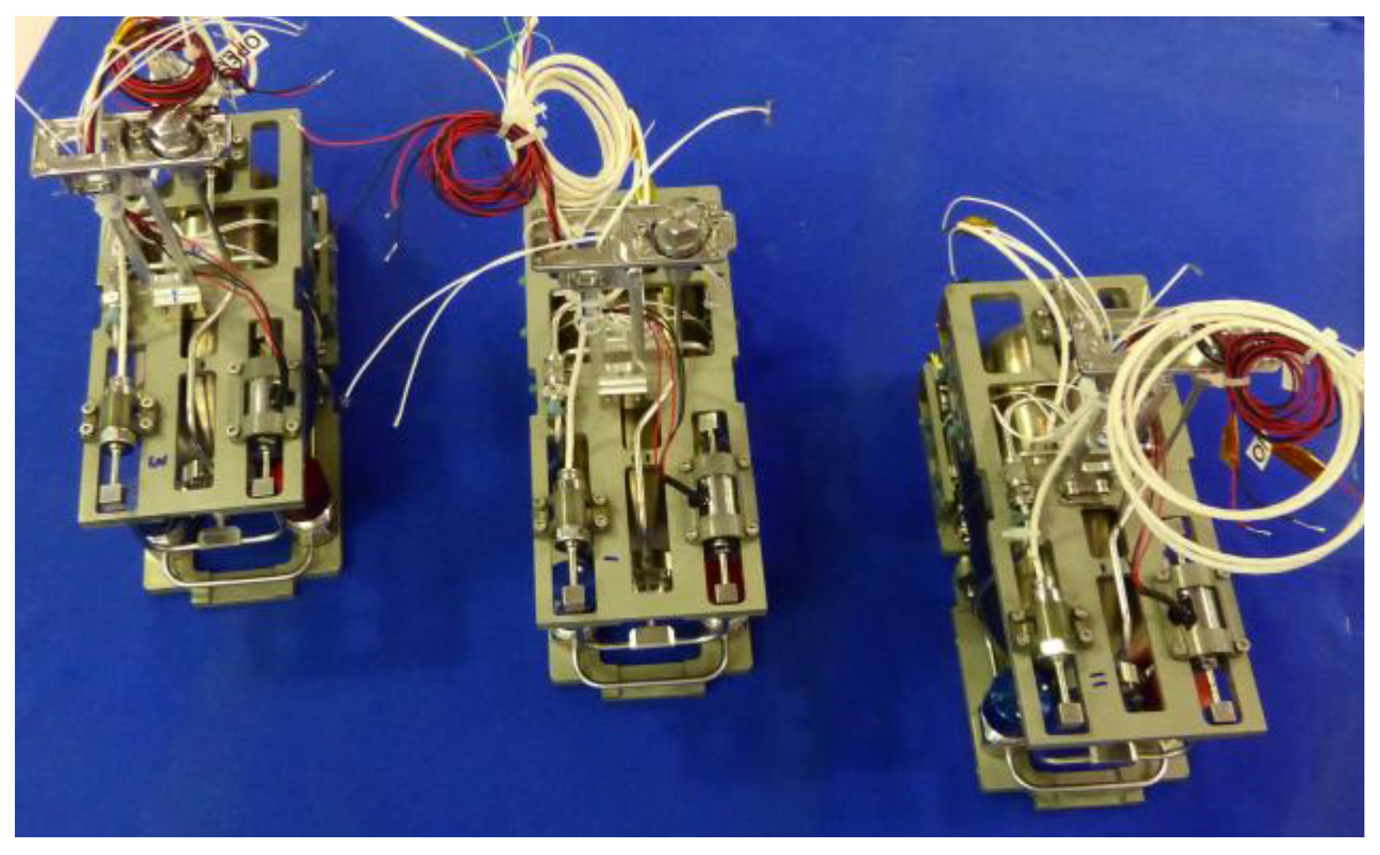
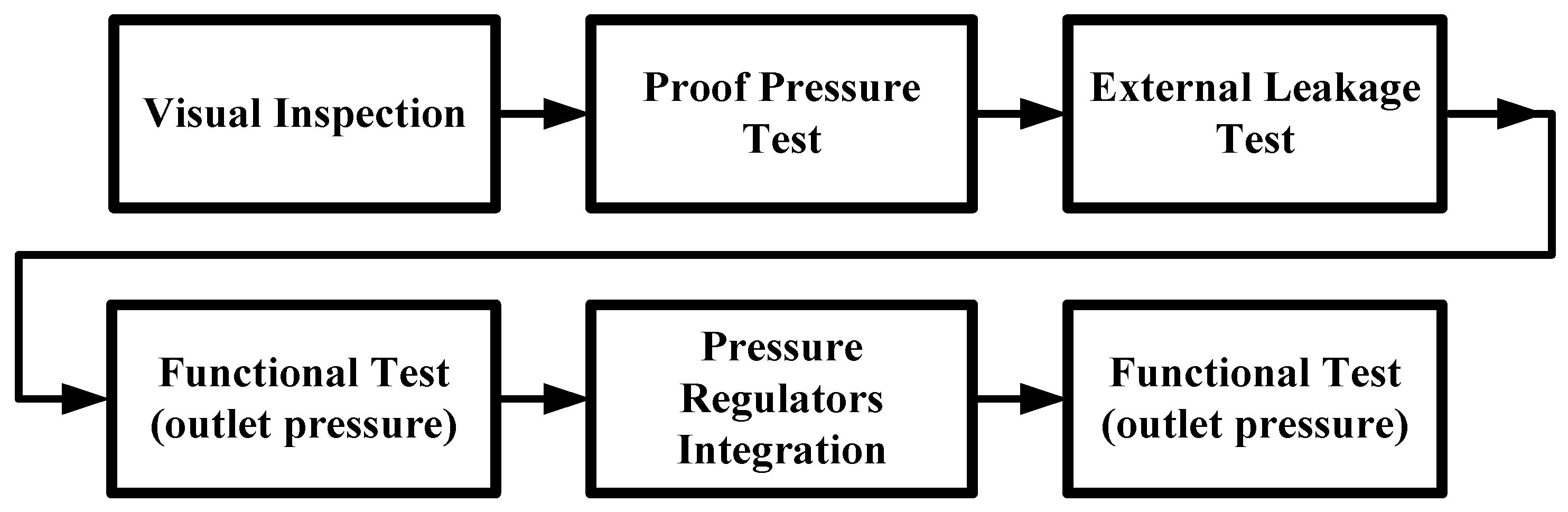
7. Propulsion System Integration and Tests

The propulsion system was integrated in a clean room environment to assure proper cleanliness and prevent any particulates from entering the system. All components were visually examined and tubes properly cleaned before being integrated into the propulsion system. The three integrated propulsion systems are presented in Figure 18. After propulsion system integration, a set of tests and checks were performed, including an end-to-end system test, to verify system operation before delivery. The tests and checks are presented in Figure 19.
First, a visual inspection was conducted for the integrated propulsion systems during which careful attention was given to all fittings, brazed joints, and welded joints. Subsequently, the propellant tank was pressurized with nitrogen to 1.5×MEOP (240 bar) and immediately after was de-pressurized through the FVV. Following the pressurization cycle, a full external leak test was performed on the entire propulsion system to assure proper gas sealing for all pipeline and system part connections. Following the external leak test, the propellant tank was pressurized with nitrogen to the MEOP (160 bar) as preparation for a full system function test. When the propellant tank was pressurized, the high-pressure transducer reading was verified and the latch valve was opened to fill the low-pressure line of the propulsion system. The low-pressure transducer reading was monitored during the latch valve opening to assure a pressure increase of up to 2 bar downstream of the pressure regulators.
The last step involved the operation of the thruster assemblies by opening and closing the solenoid valves as shown in Table 4. Each of the 12 thrusters were separately operated in a sequence of 20 ON/OFF cycles during which the solenoid valve was open for 0.1 s and closed for 0.9 s, following 5 s of continuous operation. Each continuous thruster operation was verified by ear as the ejected gas was sufficiently loud when ejected. After checking each one of the thruster assemblies separately, all four thrusters were operated simultaneously for each of the three satellites.
Following the above-specified tests, the three propulsion systems were delivered to the Asher Space Research Institute for integration into the three Adelis-SAMSON nano-satellites. The propulsion system is planned to be vibration-tested again in the future with the entire satellite. Propellant loading for all three nano-satellites will be conducted before delivery to the launch site.

8. Concept of Operations

We present a brief overview of the propulsion system concept of operations for the successful execution of the Adelis-SAMSON mission.
The three Adelis-SAMSON nano-satellites are to perform GEO-location of an RF emitter on Earth using formation flying. To do so, the three nano-satellites must maintain relative distances of 1 km to 250 km to allow sufficient line-of-sight duration to the ground. Total mission duration is one year. This is achieved by a relative change of each nano-satellite’s semi-major axis, thus changing its altitude and orbital period. The original idea for the mentioned controller was based on References [4,19] and evolved over time to match the actual mission needs. Additionally, after launch, the satellites may be scattered due to release mechanism inaccuracies [20], thus requiring initial satellite positioning in the designated orbits. Lastly, during the mission, attitude corrections may be needed to correct for natural satellite rotation drifts. For the above three reasons, the Adelis-SAMSON propulsion system carries out three main functions: (a) maintaining satellite formation; (b) correcting launch positioning inaccuracies; and (c) attitude control. We hereby discuss each of these three applications:
(a)
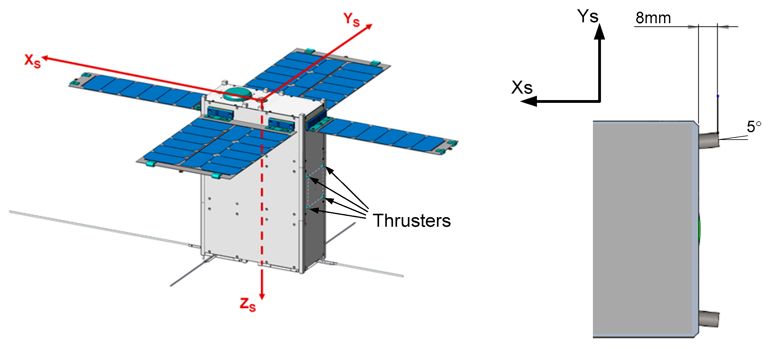
Maintaining satellite formation—To maintain satellite formation, each satellite operates all four thrusters simultaneously for the duration of 3 s, thus generating an impulse bit of approximately 0.25 N-s. Each propulsion system contains sufficient propellant to allow for over 500 such operations. Due to thruster positioning symmetry (see Figure 10), operation of all four thrusters simultaneously greatly reduces the generation of parasitic moments, resulting in each thruster’s installation angle. To optimize each satellite maneuver, the thrusters are operated on the ascending node. Orbit corrections may be performed once in every orbit lap until the desired semi-major axis is reached for the maneuvering satellite. Ultimately, allocating each satellite on a different orbit with different altitudes enables one to control the relative distances between the satellites.
The propulsion system operation philosophy is as follows. The three nano-satellites constantly assess the relative along-track distance ( y i j ), relative mean semi-major axis ( Δ a ¯ i j ) , and relative mean argument of latitude ( λ ¯ i j ). If the relative distance is outside the pre-defined envelope of 1 km (dmin)–250 km (dmax), then the nano-satellites will operate their propulsion systems according to the following algorithm presented in Equation (3) and alternatively in Table 5.
y i j > d m a x T V = { 0 Δ a ¯ i j λ ¯ i j 0 T c o n s t Δ a ¯ i j λ ¯ i j < 0 , Δ a ¯ i j > 0 T c o n s t a ¯ i j λ ¯ i j < 0 , Δ a ¯ i j < 0 y i j < d m i n T V = { 0 Δ a ¯ i j λ ¯ i j 0 T c o n s t Δ a ¯ i j λ ¯ i j > 0 , Δ a ¯ i j > 0 T c o n s t a ¯ i j λ ¯ i j > 0 , Δ a ¯ i j < 0 j = { i + 1 i = 1 , 2 , 3 N 1 1 i = N
where TV is the thrust vector that can only be pointed in the direction of the satellite’s velocity vector (negative or positive) with constant thrust (Tconst). The i and j indices represent the satellite indices as this controller can support a formation of N satellites.
The benefits of the above algorithm are:
  • Cyclic algorithm to reduce inter-satellite data traffic.
  • Constant thrust (Tconst) at a constant duration maneuver. A short maneuver (several seconds during each operation) makes it unnecessary to change the satellite attitude during thrust generation. Thrust is applied only in the velocity vector direction (TV).
  • Slow control cycle. Maneuvers are conducted only on the ascending node during daytime. If the maneuver is insufficient to complete the required orbit correction, then an additional maneuver is applied on the next lap.
It should be noted that to perform the maneuvers without any parasitic moments induced on the nano-satellite, the thrust generated by each thruster should be as close as possible to that generated by the other thrusters. By the same token, an applied thrust of precisely 20 mN per thruster is not necessary. In fact, if the generated thrust is much lower or higher yet at the same order of magnitude as the thrust requirement, then all maneuvers can still be executed successfully by operating the thrusters more, or fewer, times to reach the desired orbit.
(b)
Launch positioning corrections—Due to satellite injection during launch, the three nano-satellites may start drifting from one another, depending on their initial release velocity vectors. To prevent drifting, it was decided by the mission engineers that all three nano-satellites shall correct their initial orbits within approximately 24 h after launch. Initial orbit corrections shall be performed according to the same operation philosophy as for maintaining satellite formation—all four thrusters are operated simultaneously for 3 s once in every lap until the desired orbit is reached.
(c)
Attitude control—Each thruster assembly was installed with a 5-deg angle in order to generate body rotation moments when operated individually. In the same manner, the operation of any two adjacent thrusters generates rotation moments. The Adelis-SAMSON nano-satellites can perform attitude control using their reaction wheels and magneto-torquers. Nevertheless, the propulsion system can be used as a backup tool for attitude control if needed.

9. Conclusions

The fabrication, qualification, and integration of the Adelis-SAMSON nano-satellite propulsion system were presented. Ultimately, the propulsion system will be used to initially position the nano-satellites in orbit and maintain a tight three-satellite formation in space to allow for accurate geo-location of an RF signal on Earth.
First, we presented the reasoning behind the propulsion technology selection and choice of propellant type. We presented the propulsion system architecture and explained its simple operation scheme. More specifically, we showed the propulsion system division into high- and low-pressure branches as well as the components involved in each branch. Subsequently, we overviewed the particular role and qualification processes of four of the propulsion system’s components, all of which were produced at Rafael. These are the propellant tank, thruster assembly, pressure regulators, and fill and vent valve. We showed that the qualification process validated the functionality of each one of the above components. In particular, the thruster assembly may be used in cold gas propulsion systems where mild inlet pressure of 2 bar can be transformed to thrust levels in the order of tens of millinewtons, depending on the gas type. We then presented the tests conducted on all three propulsion systems following integration and before delivery for integration within the Adelis-SAMSON nano-satellites.
Finally, we presented the propulsion system’s operation methodology. We showed that both initial orbit positioning and formation maintenance can be achieved by employing all four thrusters simultaneously for 3 s per orbit lap. At the same time, satellite attitude control may be performed by employing one or two thrusters, thus creating the required rotation moments on the nano-satellite.
The Adelis-SAMSON propulsion system may serve as a viable propulsion solution for nano-satellites due to its low volume, moderate thrust, and simplicity of use. The three Adelis-SAMSON nano-satellites are slated for launch in late 2019.

Author Contributions

M.Z. was responsible for the design of the flight units, as well as performing the majority of the testing activities. D.R.L. was responsible for the initial conceptual design phases, article writing and analysis of the thrust measurements. E.E. performed the thrust measurements, participated in the propellant tank experiments and provided the propulsion system concept of operations. A.K. was responsible for the execution of all project activities as well as the integration into the Adelis-SAMSON nano-satellites.

Funding

This research was funded by the Adelis foundation.

Acknowledgments

The authors would like to thank Vladimir Balabanov and Hovhannes (Hovik) Agalarian for their continuous support in most phases of the project.

Conflicts of Interest

The authors declare no conflicts of interest.

References

  1. Kulu, E. Nanosatellite & CubeSat Database. 2019. Available online: http://www.nanosats.eu/ (accessed on 27 April 2019).
  2. You, Z. Space Microsystems and Micro/Nano Satellites, 1st ed.; Butterworth Heinemann: Oxford, UK, 2017; ISBN 13: 978-0128126721. [Google Scholar]
  3. Gurfil, P.; Herscovitz, P.; Pariente, M. SSC12-VII-2 The SAMSON Project–Cluster Flight and Geolocation with Three Autonomous Nano-satellites. In Proceedings of the 26th Annual AIAA/USU Conference on Small Satellites, Logan, UT, USA, 13–16 August 2012. [Google Scholar]
  4. Mazal, L.; Pini, G. Closed-Loop Distance-Keeping for Long-Term Satellite Cluster Flight. Acta Astronaut. 2014, 94, 73–82. [Google Scholar] [CrossRef]
  5. Anis, A. Cold Gas Propulsion System–An Ideal Choice for Remote Sensing Small Satellites. In Remote Sensing–Advanced Techniques and Platforms; Escalante-Ramirez, B., Ed.; IntechOpen: London, UK, 2012. [Google Scholar] [CrossRef]
  6. Anis, A. Design & Development of Cold Gas Propulsion System for Pakistan Remote Sensing Satellite (PRSS). In 2008 2nd International Conference on Advances in Space Technologies; Curran Associates Inc.: Dutchess County, NY, USA, 2008. [Google Scholar]
  7. Lemmer, K. Propulsion for CubeSats. Acta Astronaut. 2017, 134, 231–243. [Google Scholar] [CrossRef]
  8. Adler, S.; Warshavsky, A.; Peretz, A. Low-Cost Cold-Gas Reaction Control System for Sloshsat FLEVO Small Satellite. J. Spacecr. Rocket. 2005, 42, 345–351. [Google Scholar] [CrossRef]
  9. Lev, D.R.; Herscovitz, J.; Zuckerman, Z. Cold Gas Propulsion System Conceptual Design for the SAMSON NanoSatellite. In Proceedings of the 50th AIAA/ASME/SAE/ASEE Joint Propulsion Conference (JPC), Cleveland, OH, USA, 28–30 July 2014. [Google Scholar]
  10. Lev, D.R.; Herscovitz, J.; Kariv, D.; Mizrachi, I. Heated Gas Propulsion System Conceptual Design for the SAMSON Nano-Satellite. J. Small Satell. 2017, 6, 551–564. [Google Scholar]
  11. Israel 21C. Israel to Launch Synchronized Satellites into Space. Uncovering Israel. 2018. Available online: https://www.israel21c.org/israel-to-launch-synchronized-satellites-into-space/ (accessed on 8 May 2019).
  12. NASA. General Environmental Verification Standards (GEVS) for GSFC Flight Programs and Projects; GSFC-STD-7000A; NASA: Washington, DC, USA, 2005.
  13. Sai Global. Military Standard MIL-STD-1522A (USA), Standard General Requirements for Safe Design and Operation of Pressurized Missile and Space Systems; Dept. of Air Force; Sai Global: Sydney, Australia, 1984. [Google Scholar]
  14. European Space Standards. ECSS-E-ST-32-11C, Modal Survey Assessment; European Cooperation for Space Standardization: Noordwijk, The Netherlands, 2008. [Google Scholar]
  15. Turner, M.J. Rocket and Spacecraft Propulsion, 2nd ed.; Springer: Chichester, UK, 2006. [Google Scholar]
  16. Spisz, E.W.; Brinich, P.F.; Jack, J.R. Thrust Coefficients in Low-Thrust Nozzles; Technical Report# NASA TN D-3056; National Aeronautics and Astronautics Administration (NASA): Washington, DC, USA; Lewis Research Center: Cleveland, OH, USA, 1965.
  17. O’Gara, M.R. A CFD Investigation of Axisymmetric Microthruster Nozzles for Use on Nano-Satellites. Master’s Thesis, Embrie-Riddle Aeronautical University, Daytona Beach, FL, USA, 2007. [Google Scholar]
  18. The Lee Company. Solenoid Valves–VHS Series, Datasheet. 2019. Available online: https://www.theleeco.com/products/electro-fluidic-systems/solenoid-valves/dispensing-valves/vhs-series-solenoid-valves/ (accessed on 30 Jul 2019).
  19. Mazal, L.; Mingotti, G.; Gurfil, P. Optimal On–Off Cooperative Maneuvers for Long-Term Satellite Cluster Flight. J. Guid. Control Dyn. 2014, 37, 391–402. [Google Scholar] [CrossRef]
  20. Wen, C.; Zhang, H.; Gurfil, P. Orbit Injection Considerations for Cluster Flight of Nanosatellites. J. Spacecr. Rocket. 2015, 52, 196–208. [Google Scholar] [CrossRef]
Figure 1. Schematic of the Adelis-SAMSON satellite cold gas propulsion system.
Aerospace 06 00091 g001
Figure 2. Left: Photograph of the integrated Adelis-SAMSON satellite propulsion system. Right: Illustration of the propulsion system inside the Adelis-SAMSON nano-satellite [11].
Aerospace 06 00091 g002
Figure 3. High- (left) and low- (right) pressure sections of the Adelis-SAMSON propulsion system.
Aerospace 06 00091 g003
Figure 4. Photograph of the Adelis-SAMSON propellant tank (left) and illustration of a cross section view of the Adelis-SAMSON propellant tank (right).
Aerospace 06 00091 g004
Figure 5. Flow chart showing the sequential acceptance tests performed on each of the five propellant tanks produced for the Adelis-SAMSON nano-satellite.
Aerospace 06 00091 g005
Figure 6. Flow chart showing the qualification process of the propellant tank for the Adelis-SAMSON nano-satellite.
Aerospace 06 00091 g006
Figure 7. Figures showing (a) the pressure cycling test and (b) temperature cycling test, as part of the propellant tank qualification procedure.
Aerospace 06 00091 g007
Figure 8. Sinusoidal (left) and random vibration (right) levels inflicted on the propellant tank as part of the propellant tank qualification procedure.
Aerospace 06 00091 g008
Figure 9. Left: Photograph of the Adelis-SAMSON nano-satellite thruster nozzle. Right: Illustration of a cross section of the Adelis-SAMSON nano-satellite thruster assembly showing its leading dimensions.
Aerospace 06 00091 g009
Figure 10. Illustration of the thrusters’ locations and positioning on the Adelis-SAMSON nano-satellites.
Aerospace 06 00091 g010
Figure 11. Experimental setup used to assess the thrust generated by the 16 thruster assemblies produced for the Adelis-SAMSON nano-satellites.
Aerospace 06 00091 g011
Figure 12. Measured thrust for the 16 thrusters at an inlet pressure of 60 psig (black) and 30 psig (blue) under atmospheric environment and using nitrogen as a propellant.
Aerospace 06 00091 g012
Figure 13. Calculated thrust at different exit pressure ratio values (Pe/Pa) for an inlet pressure of 60 psig and measured thrust.
Aerospace 06 00091 g013
Figure 14. Illustration (left) and photograph (right) of the Adelis-SAMSON pressure regulators.
Aerospace 06 00091 g014
Figure 15. Flow chart showing the sequential acceptance tests performed on each of the pressure regulators produced for the Adelis-SAMSON nano-satellite.
Aerospace 06 00091 g015
Figure 16. Photograph (right) and illustration (left) of the Adelis-SAMSON Fill and Vent Valve (FVV).
Aerospace 06 00091 g016
Figure 17. Flow chart showing the sequential acceptance tests performed on Fill and Vent Valves (FVVs) produced for the Adelis-SAMSON nano-satellites.
Aerospace 06 00091 g017
Figure 18. Photograph of the three integrated Adelis-SAMSON propulsion systems.
Aerospace 06 00091 g018
Figure 19. Flow chart showing the post-integration tests and checks for the Adelis-SAMSON nano-satellite propulsion system.
Aerospace 06 00091 g019
Table 1. Adelis-Space Autonomous Mission for Swarming and geOlocation with Nano-satellites (SAMSON) satellite propulsion system requirements.
Satellite/Mission PropertyConstraint/GuidelineRemarks
Itot>150 N·sRequired total impulse per satellite for a one-year mission
mps<2 kgPropulsion system mass
(including propellant)
Vps<100 mm × 100 mm × 210 mmPropulsion system volume
Propellant typeNon-toxic, non-flammable, non-explosiveStudent project constraint
Electrical power<10 WFor all operational phases
Thrust (20 mN per thruster)80 mN (For the entire propulsion system)
Table 2. Components of the Adelis-SAMSON satellites’ propulsion system.
ComponentMass per Unit (gr)Quantity per SatelliteSupplierRemarks
Propellant tank4251Rafael
Krypton propellant468N/AProcuredAssuming Isp = 34 s [9] with no propellant contingency
Latch valve501Marotta Controls
Filter381RafaelFilter element is procured
Pressure regulator (high pressure)1101Rafael
Pressure regulator (low pressure)1101Rafael
Thruster assembly: Nozzle, Solenoid valve164Technion, The LEE CompanyAssembly by Rafael
High pressure transducer281L’Essor Français Electronique (EFE)
Low pressure transducer281L’Essor Français Electronique (EFE)
Fill and vent valve481Rafael
Tubes, plates, brackets, and fasteners592N/ATechnion
Overall1961
Table 3. Propellant tank properties.
PropertyValueRemarks
Dry mass425 gr
MaterialTi-6Al-4V
External dimensions: Capsule-shaped
Length170 mm
Diameter82 mm
Inner volume680 ccfor 468 gr of krypton
Maximum Expected Operating Pressure (MEOP) 160 bar@34 °C
Req. burst pressure320 bar2×MEOP
Table 4. Thruster assembly operation test sequence for the entire propulsion system.
Check TypeOperation CharacteristicsNumber of Tests
Pulse0.1 s ON; 0.9 s OFF20
Steady state5 continuous seconds 1
Steady state (all valves)5 continuous seconds 1
Table 5. Propulsion system operation methodology to maintain nano-satellite formation.
Relative Satellite DistanceRelative VelocityOperation
<1 kmDistance decreasingSemi-major axis difference increase
<1 kmDistance increasingNo action
>250 kmDistance decreasingNo action
>250 kmDistance increasingSemi-major axis difference decrease

