In this section, the impact of the modal propagation angle on the excitation of tonal RSI noise is analyzed. First, in
Section 5.1, this is investigated analytically and numerically and validated experimentally using the baseline fan stage. Secondly, in
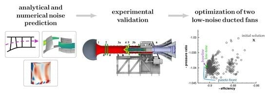
Section 5.2, the noise reduction potential resulting from the modal propagation angle is demonstrated on two new fan stages, a low-tone fan and a low-broadband fan. For both fans, the rotor and stator blades are designed for aerodynamic optimization. In
Section 5.2.2 and
Section 5.2.3, the optimization results are outlined and the acoustic noise emission is examined.
5.1. Acoustic Validation Using the Baseline Fan
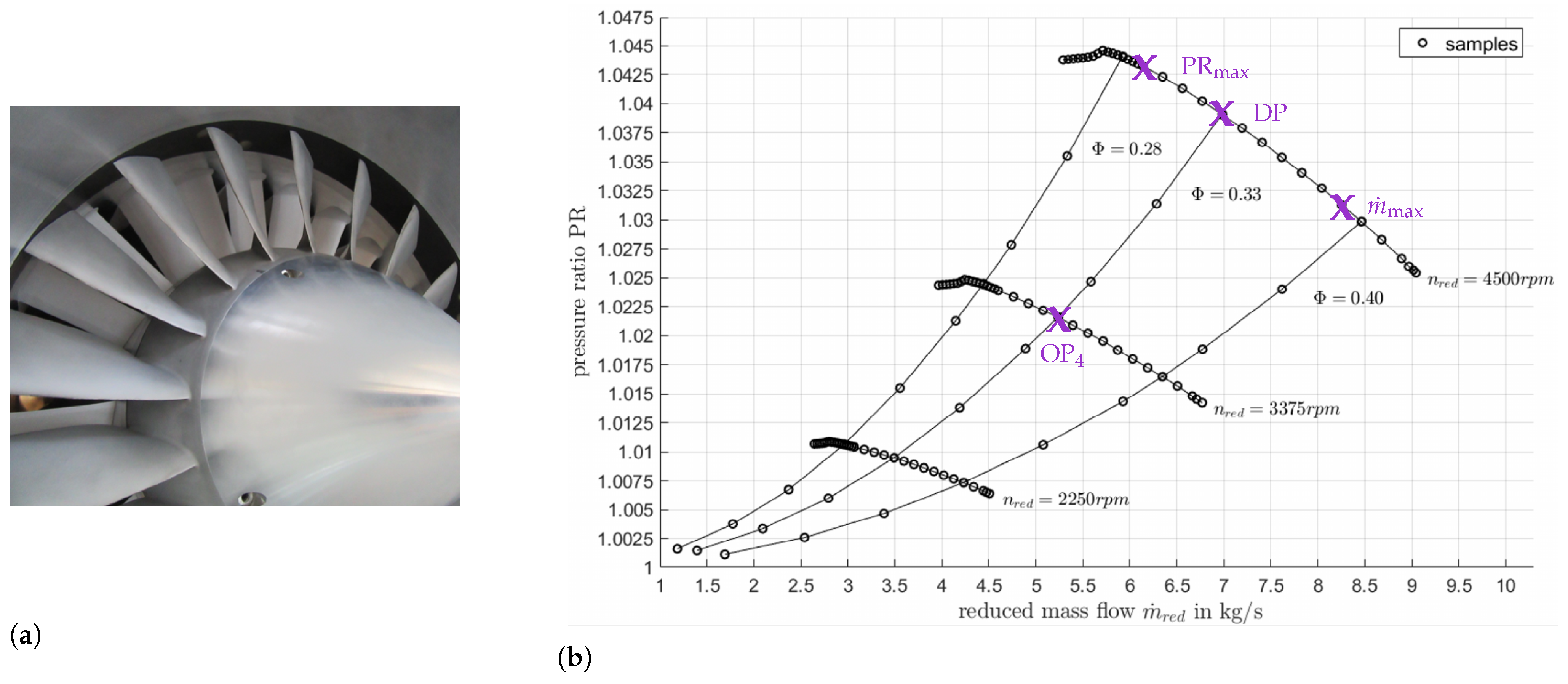
The current CRAFT baseline fan stage is equipped with an 18-blade rotor and a 21-vane stator. For the subsequent comparison of the RSI noise levels between measurements and prediction, the axial distance between the rotor trailing edge and stator leading edge is 63 mm, measured at the casing. The comparison is performed at the three operating points DP,
and
(see
Table 1). A detailed description of the pure experimental data can additionally be found in [
33].
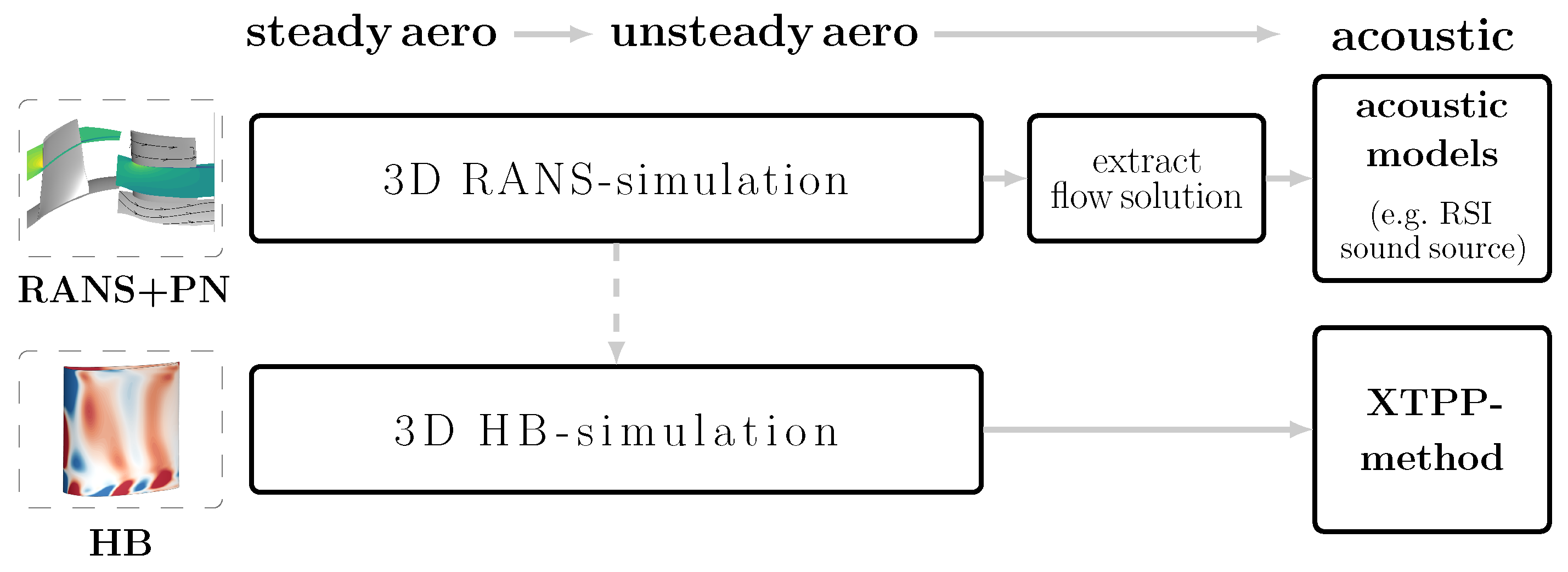
In
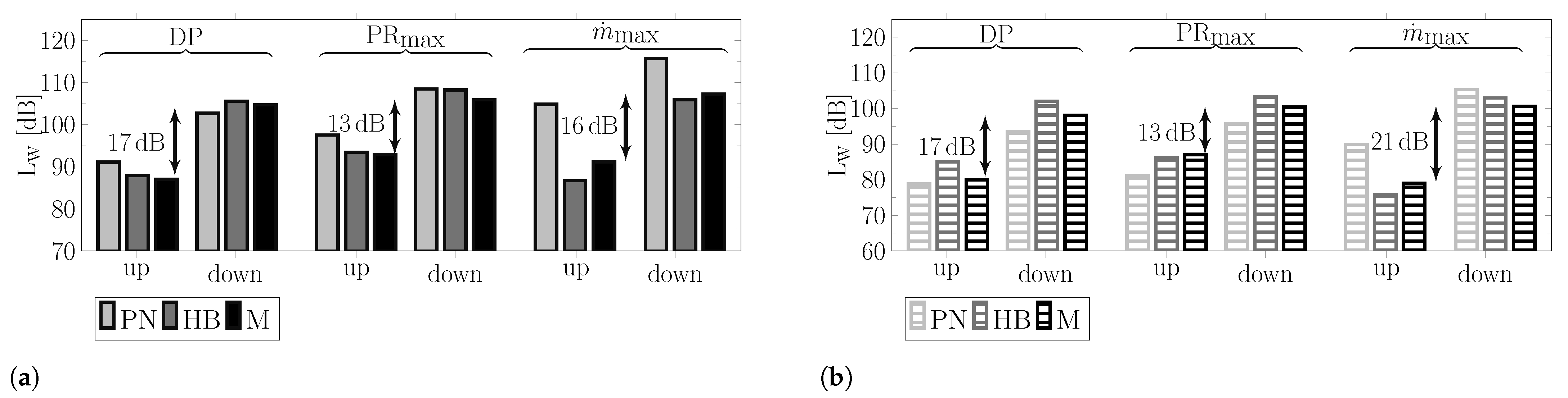
Figure 9, the tonal RSI sound power levels are compared between measurements (M), a fully analytical prediction (PN) and a fully numerical prediction (HB). Note that the arrows correspond to the experimental results and indicate the differences between upstream and downstream noise radiation.
Figure 9a shows the sound power levels of the dominantly excited BPF1 azimuthal mode
, and
Figure 9b shows the sound power levels of the dominantly excited BPF2 azimuthal mode
. Note that for both
and
, only one radial mode,
, is excited.
For all considered operating points, the tonal noise emission of the CRAFT baseline fan stage is mainly dominated by BPF1 and BPF2. Moreover, the experimental results indicate a significant difference between the upstream and downstream radiated tonal BPF1 and BPF2 noise levels. Overall, the numerical simulation and analytical noise prediction both accurately reproduce this level difference and provide good agreement with the experimental results. However, for operating conditions, the fully analytical prediction provides higher absolute values.
For all operating conditions, the upstream noise radiation of the dominantly excited BPF1 mode (
) is more than 13 dB lower than that of the downstream. The BPF2 shows an identical radiation characteristic. The noise levels of the dominantly excited mode (
) are also more than 13 dB lower upstream. The reason for the significantly different noise radiation upstream and downstream can be found in the excitation of the fan tones. For the excitation of modes (
) and (
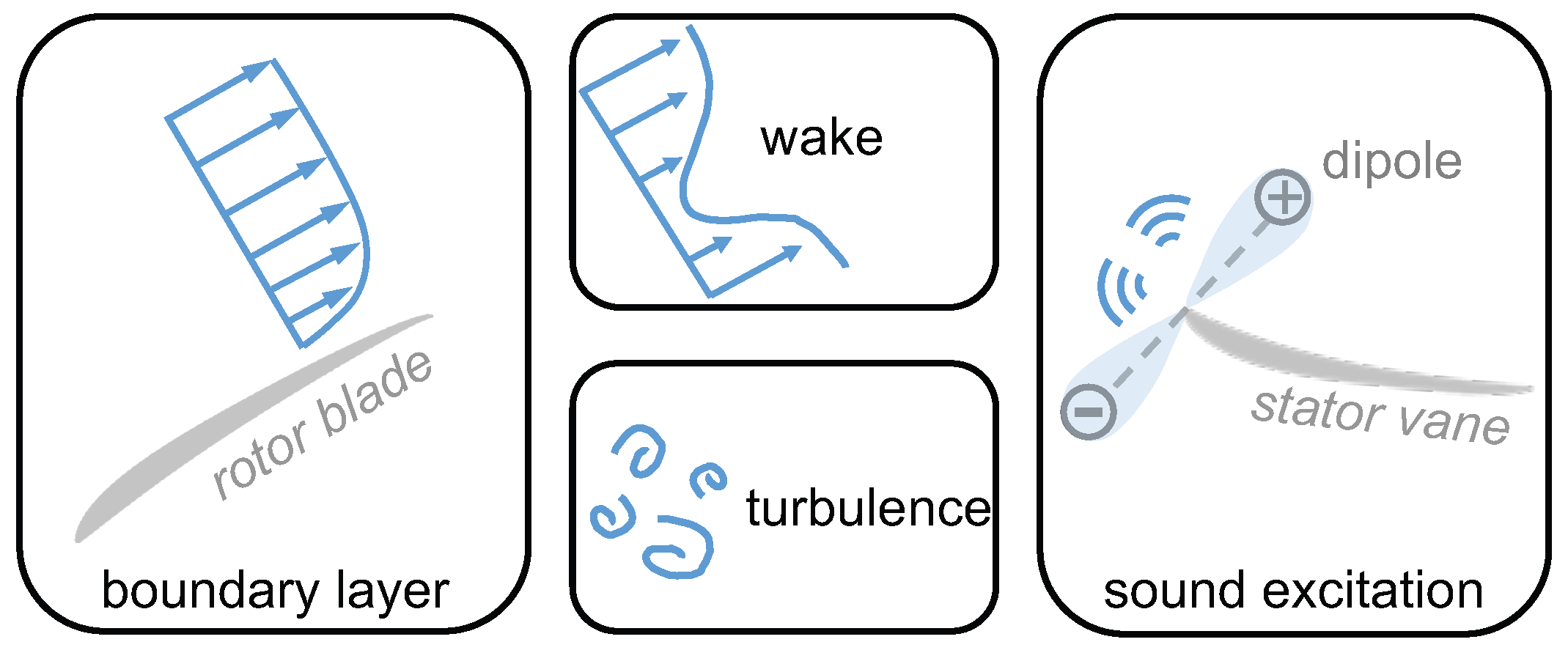
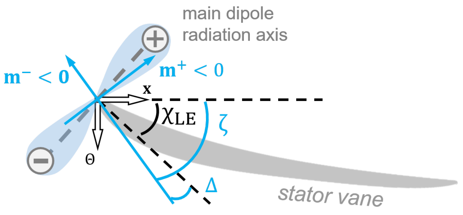
) at the stator leading edge, the scenario schematically illustrated in
Figure 2 applies. Upstream, the modal propagation angles are almost parallel to the stator leading edge angle. As a result, the acoustic modes are excited weakly upstream. By contrast, downstream, a stronger noise excitation of the modes (
) and (
) occurs, as the propagation angles downstream are almost perpendicular to the stator leading edge angle. This is shown in
Table 3, which depicts the difference
between the stator leading edge angle and the modal propagation angle obtained from HB simulations for the dominantly excited BPF1 and BPF2 modes at design,
and PR
max operating conditions. For all considered operating points and all acoustic modes, upstream, the modal propagation angle is nearly parallel to the stator LE angle (
), and downstream, it is nearly perpendicular (
). Thus, the upstream noise excitation of the baseline fan stage shows a strong dependence on the modal propagation angle over a wide operating range. This leads to significantly lower sound power levels upstream compared to downstream. Similar values for
are obtained from fully analytical predictions and measurements. These values are listed in
Table A1 in
Appendix B.
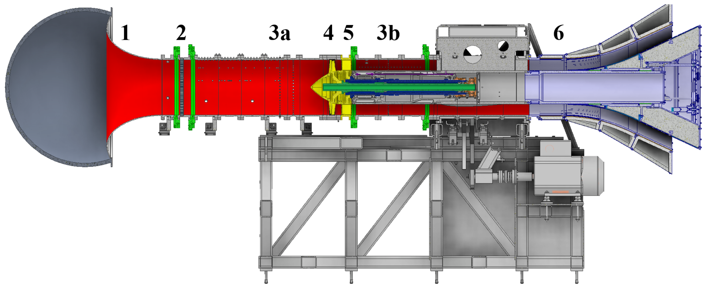
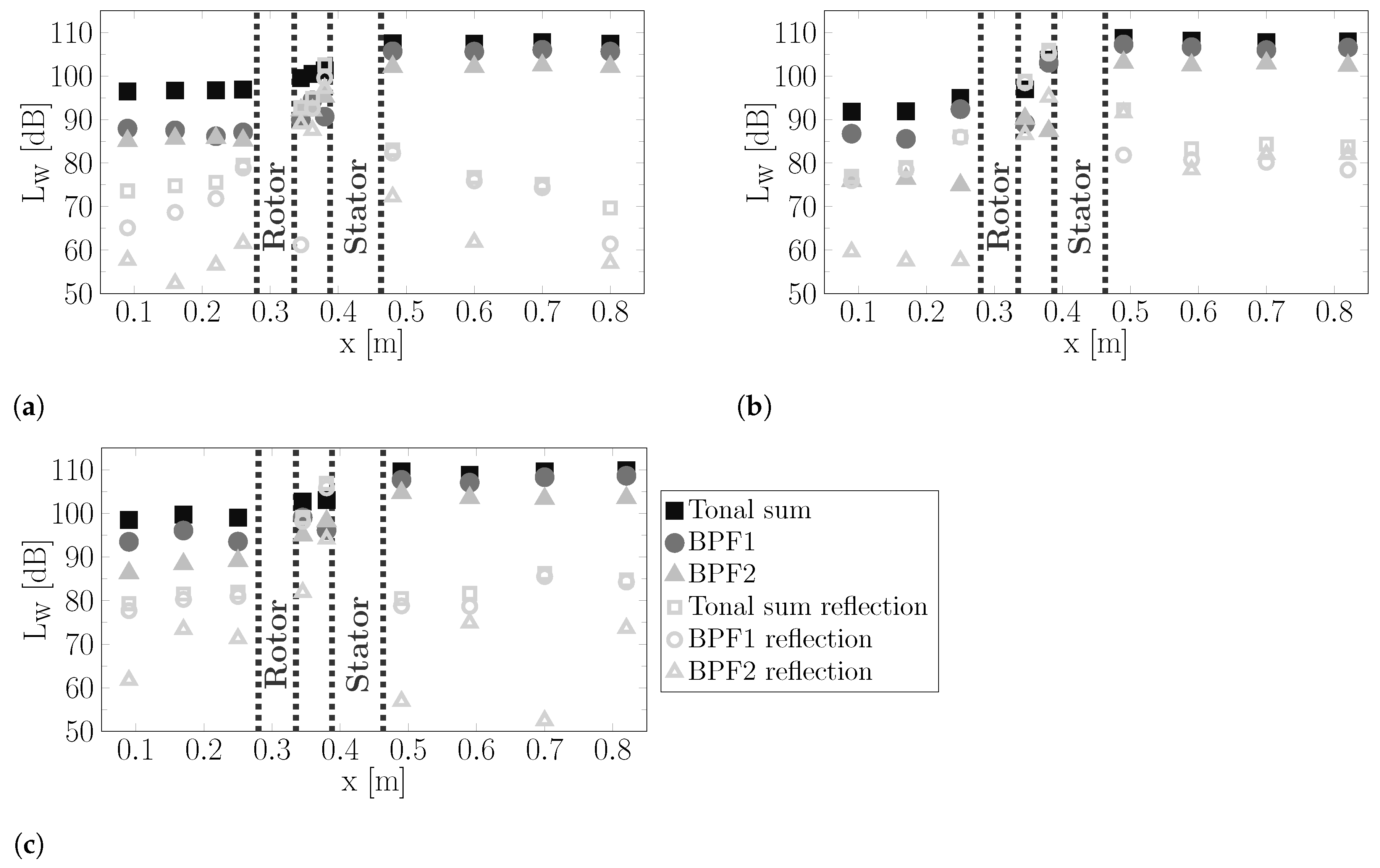
Figure 10a shows the tonal RSI noise obtained from an HB simulation in design operating conditions. The sound power levels are plotted along the axial position within the flow channel, where location 3a from
Figure 6 is at position
m and locations 4 and 5 are at position
m and
m, respectively. The numerical simulation confirms that the difference between the upstream and downstream tonal RSI levels arises from the noise excitation. A difference of more than 10 dB is predicted between upstream and downstream noise levels under design conditions. The numerical data indicate that the transmission of sound through the rotor blade row does not dominantly contribute to the level difference between upstream and downstream. The BPF1 and BPF2 noise levels are reduced by approximately 2 dB due to transmission through the rotor blade row.
Figure 10b,c show that these findings are also valid for the two other operating points.
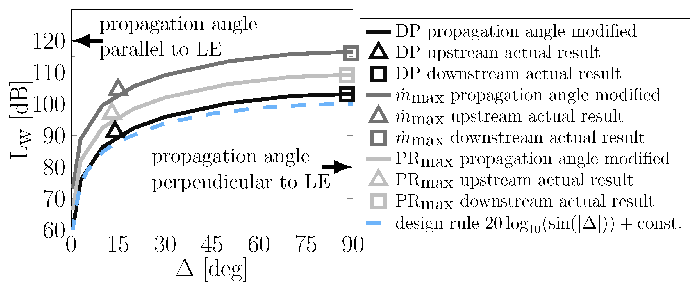
In order to further quantify the impact of the modal propagation angle on tonal noise excitation, a trend study is shown in
Figure 11. The results are calculated fully analytically using PropNoise. For the trend study, the propagation angles of all cut-on BPF1 modes are intentionally manipulated in PropNoise code. The modal propagation angles are continuously varied between
and
. For
, the modal propagation angles are parallel to the stator LE angle, and for the latter case, the modal propagation angles are perpendicular to the LE angle. In
Figure 11, the resulting BPF1 sound power levels are plotted over the difference
.
The triangle and square markers indicate the actual upstream and downstream BPF1 sound power levels of the CRAFT baseline fan without any manipulation. The three curves for the three operating points are vertically shifted and are at a constant offset to each other. The results illustrate that the modal propagation angle strongly influences tonal noise excitation. The difference in sound power level between and is approximately 40 dB, according to the analytical prediction.
Based on the results obtained from the analysis of the modal propagation angle, a design rule for future acoustic designs of low-speed fan stages could be derived. Using Equation (
5), it can be deduced that the expected noise level reduction compared to the case
can be estimated with the factor
Equation (
7) shows the correlation between the estimated noise level reduction and the difference
between the stator leading edge angle and modal propagation angle. In practice, this means that once the rotor and stator blade numbers and the stagger angles are known, the expected reduction in noise level compared to
can be calculated using Equation (
7). In
Figure 11, this design rule is visualized by the dashed line and plotted for
.
As an intermediate conclusion, the analytical, numerical and experimental data illustrate that the modal propagation angle significantly impacts the excitation of tonal RSI noise for all considered operating points. Also, in off-design conditions, for the baseline fan, the tonal RSI noise is reduced by more than 10 dB upstream compared to downstream, as the modal propagation angle upstream is nearly parallel to the stator leading edge angle. Thus, a tonal advantage is achieved upstream due to the impact of the modal propagation angle on noise excitation.
The experimental data obtained from the CRAFT test facility and the baseline fan provide, first, a validation of the analytical and numerical results, and second, experimental evidence that the modal propagation angles strongly influence the excitation of tonal RSI noise. Especially for low-speed fan stages, where only a few azimuthal modes are cut-on, tonal RSI noise can be significantly reduced using the described effect. The acoustic benefits can be achieved with an appropriate choice of the rotor and stator blade numbers, since the blade numbers determine the excited Tyler and Sofrin mode orders, and with the azimuthal mode orders, the modal propagation angles are defined, as indicated in Equation (
1). In a fan pre-design process, the stator leading edge angle is typically known at an early stage, as it directly results from rotational speed and fan pressure ratio. Consequently, the blade numbers should be iterated until the propagation angles of the dominantly excited modes are preferably parallel to the stator leading edge angle. To demonstrate the impact of the modal propagation angle on noise generation, this design-to-noise process is subsequently applied to select blade numbers for two new, low-count OGV fan stages, which are intended to be operated in the CRAFT test facility.
5.2. Low-Count OGV Fan Stages
The analyzed noise reduction potential of the effect resulting from the modal propagation angle is demonstrated on two low-noise fan stages with fewer stator than rotor blades. Both new, low-count OGV fans are designed according to the design-to-noise process outlined at the end of
Section 5.1. Consequently, in order to apply the described effect to low-count OGV fan stages and to achieve acoustic benefit, the rotor and stator blade numbers have to be chosen appropriately. The blade numbers of both new fans are chosen to achieve a weak tonal noise excitation due to the impact of the modal propagation angle. Thus, the blade numbers should be selected in such a way that the dominant excited modes propagate parallel to the stator leading edge angle. Due to the given flow conditions in the CRAFT test rig, the rotor and stator stagger angles are predefined. Thus, the rotor and stator blade numbers are varied in order to find suitable blade count combinations for which exactly those modes are dominantly excited with the modal propagation angle approximately parallel to the stator stagger angle (
).
Achieving an acoustic benefit based on the effect resulting from the modal propagation angle is the primary acoustic design criterion for both new low-count OGV fan stages. In addition to that, additional design criteria are defined that set further requirements regarding the acoustic behavior of the fan stages. This is important as the fans are intended to be used in a process consisting of measurements, virtual flyover simulations, auralizations and listening tests in the future. In order to achieve fundamentally different perceived noise characteristics with the same aerodynamic performance, the fan stages should also differ with regard to the following aspects:
- (a)
Different dominant noise radiation direction.
- (b)
Different ratio between tonal and broadband noise levels.
- (c)
Different base frequency.
5.2.1. Blade Count Selection
In order to assess which blade count combinations satisfy the defined requirements, analytical blade count variations are performed using RANS-based noise prediction with PropNoise (see
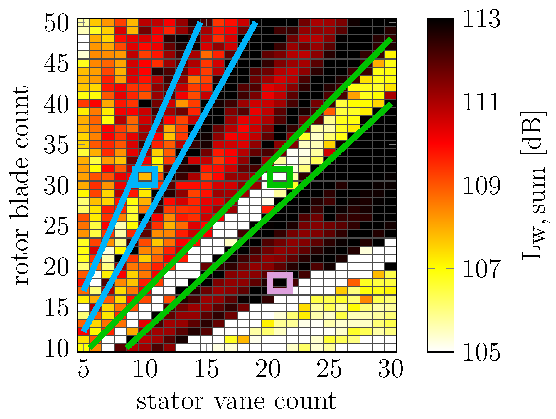
Figure 12). The baseline fan stage with 18 rotor blades and 21 stator vanes is selected as the initial configuration for the blade count variation. This configuration is framed in purple in
Figure 12. The blade count pairing of the baseline fan is chosen such that the acoustic BPF1 modes are cut-on, which results in very high sound power levels and a tonally dominant sound radiation.
Using the baseline fan, a RANS simulation is performed for the three operating points, DP,
and OP
4 (see
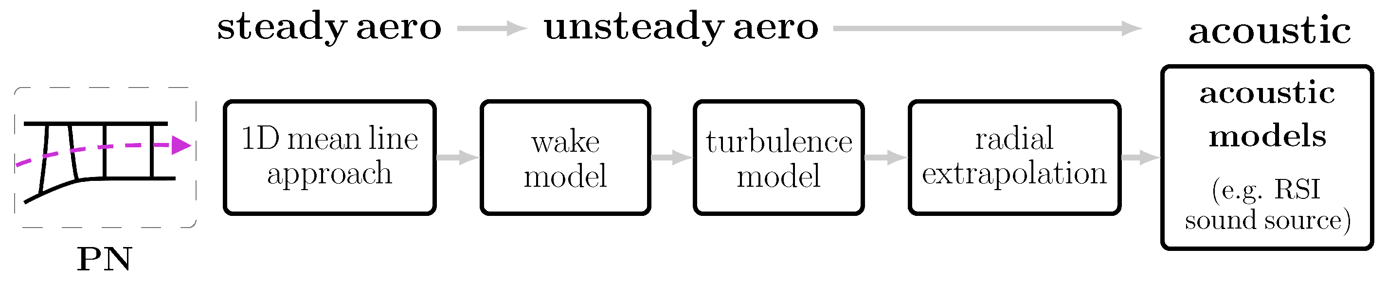
Table 1). The aerodynamic flow field is extracted from each RANS simulation and used as input for PropNoise in order to analytically predict the noise levels, following the process visualized in
Figure 5. Based on this initial prediction, the blade numbers are subsequently varied using PropNoise, and the noise levels are calculated for the new configurations for each operating point. For the blade count variation, the following assumptions are made:
All aerodynamic flow parameters and streamlines remain unchanged. Therefore, RANS simulations are performed only for the initial configuration.
The blade’s solidity is constant. Thus, the chord length changes between the configurations (e.g., the lower the blade count, the longer the blade chord).
A detailed description of the procedure applied to the RANS-based noise prediction and blade count variation with PropNoise is given in [
2,
6].
Figure 12 shows the overall sound power levels of the RSI noise source summed over the three operating points as a function of the rotor and stator blade numbers. In [
6], a similar blade count variation is performed, and several acoustically promising areas are introduced. These areas are marked in green and blue in
Figure 12. For all blade count pairings within the green area, two acoustic effects ensure that lower sound power levels occur. Firstly, the BPF1 tone is inversely cut off. Secondly, an acoustic benefit is achieved due to the effect resulting from the modal propagation angle. Due to these acoustic advantages, the first blade count combination for one of the new fan stages is selected from the green area. This fan stage consists of a 31-blade rotor combined with a 21-vane stator. As the 21-vane stator already exists (stator of the baseline fan), this blade count combination is also a good choice to keep the manufacturing costs low. The B31V21 low-count OGV fan is subsequently named the low-tone fan, and the aeroacoustic results are shown in
Section 5.2.2.
For all blade count pairings within the blue area, two acoustic effects also ensure that lower sound power levels occur. Similar to the green area, the impact of the modal propagation angle on noise excitation leads to an acoustic benefit. In addition to that, as the number of stator vanes is reduced compared to configurations in the green area, a reduction in broadband noise is obtained. Due to these acoustic benefits, the second blade count combination for one of the new fan stages is selected from the blue area. This low-count OGV fan also uses the 31-blade rotor, which is combined with a 10-vane stator. The B31V10 fan is subsequently named the low-broadband fan, and the aeroacoustic results are shown in
Section 5.2.3.
5.2.2. Low-Tone Fan: Aerodynamic Optimization and Acoustic Evaluation
The low-tone fan is equipped with a new 31-blade rotor and the 21-vane baseline stator. Since the 21-vane stator geometry already exists, only the rotor geometry is optimized using the multi-objective optimization process described in
Section 4.4.
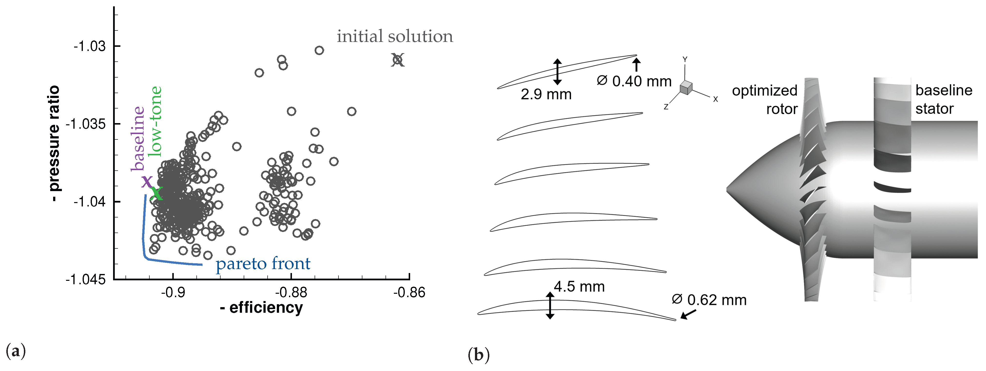
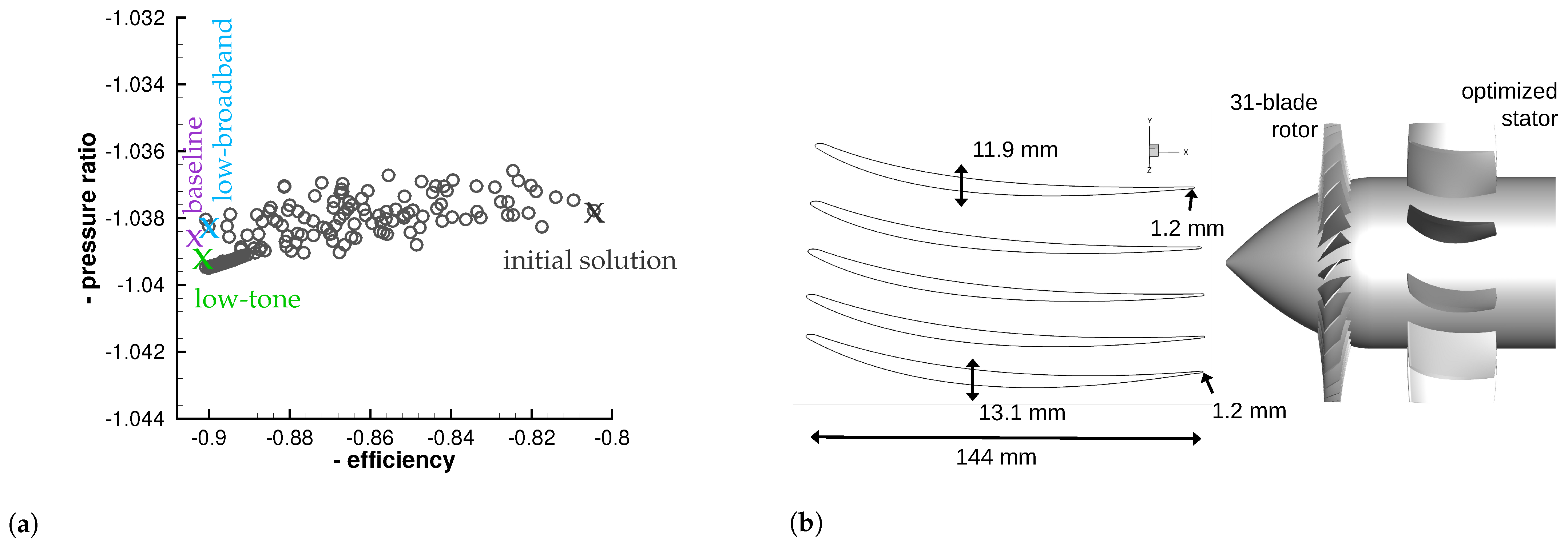
Figure 13a shows the generated members of the optimization and the Pareto front between the efficiency and pressure ratio for design operating conditions. The baseline fan stage is marked in purple, and the selected member for the 31-blade rotor is marked in green. The reason for choosing this particular member is that the fan stages should be similar to each other regarding their aerodynamic characteristics. The final geometry of the 31-blade rotor is shown on the left in
Figure 13b, and the combination of this rotor with the baseline 21-vane stator is shown on the right.
This B31V21 low-count OGV fan stage is named the low-tone fan since two acoustic effects are used to efficiently reduce the tonal noise component. Firstly, the rotor–stator blade counts are chosen such that the acoustic BPF1 modes are inversely cut off. The inverse cut-off is achieved due to the low rotor tip Mach number,
. Conventionally, a cut-off design is realized with stator vane counts larger than the rotor blade count. However, in [
6], it is verified that a cut-off design can also be achieved with fewer stator than rotor blades on condition that the rotor tip Mach number is low enough. This is called an inverse cut-off. As a design rule to achieve an inverse cut-off, the Mach number should be lower than a critical Mach number [
6]. This critical Mach number is defined as
. For the low-tone fan
is approximately
. Consequently, the inverse cut-off of the BPF1 tone is possible, since
.
Secondly, in addition to the inverse cut-off of the BPF1 tone, the blade numbers of this fan stage are chosen such that the excited BPF2 modes benefit from the impact of the propagation angle upstream. For the BPF2 tone, the acoustic mode (
) is dominantly excited. As shown in
Table 4, the propagation angle of this mode upstream is nearly parallel to the stator leading edge angle, and downstream it is nearly perpendicular. Therefore, the mode is excited more weakly upstream, leading to lower sound power levels.
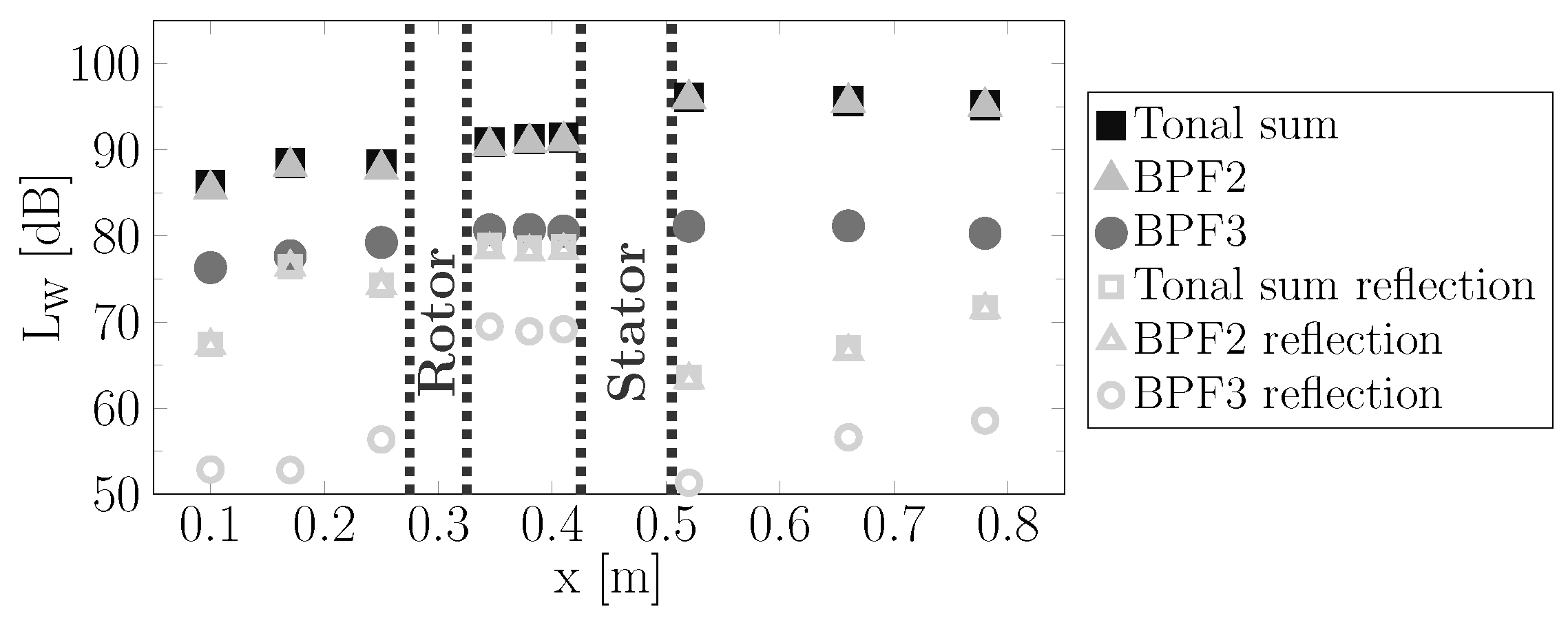
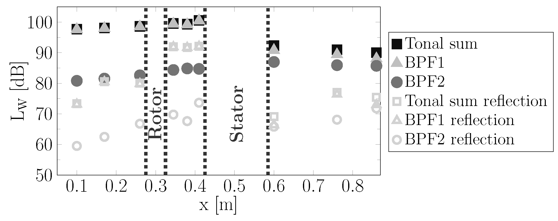
This is confirmed by the results from the HB simulation, which are shown in
Figure 14. The HB simulation is performed under design operating conditions. The results indicate a difference of 5 dB between the upstream and downstream noise excitations, leading to significantly lower noise radiation upstream. In addition to the effect resulting from the propagation angle, the upstream noise radiation also benefits from the transmission of the mode
through the rotor blade row. The reason for this is that the mode
rotates against the rotor’s rotation direction. According to Philpot [
34], modes rotating against the rotor’s rotation are attenuated more efficiently when propagating through a rotor blade row compared to modes rotating in the same direction. In the present case, the HB simulation shows that, due to the transmission through the rotor, the noise levels are attenuated by 3 dB. Adding the 5dB from the noise excitation results in a total difference of 8dB between the upstream and downstream noise radiation.
Compared to the numerical results of the baseline fan stage presented in
Figure 10a, this fan shows lower sound power levels of more than 10 dB in both upstream and downstream directions. Nevertheless, the general tonal noise radiation characteristic is similar to that of the baseline fan: lower tonal sound power levels occur upstream, whereas higher levels are observed downstream.
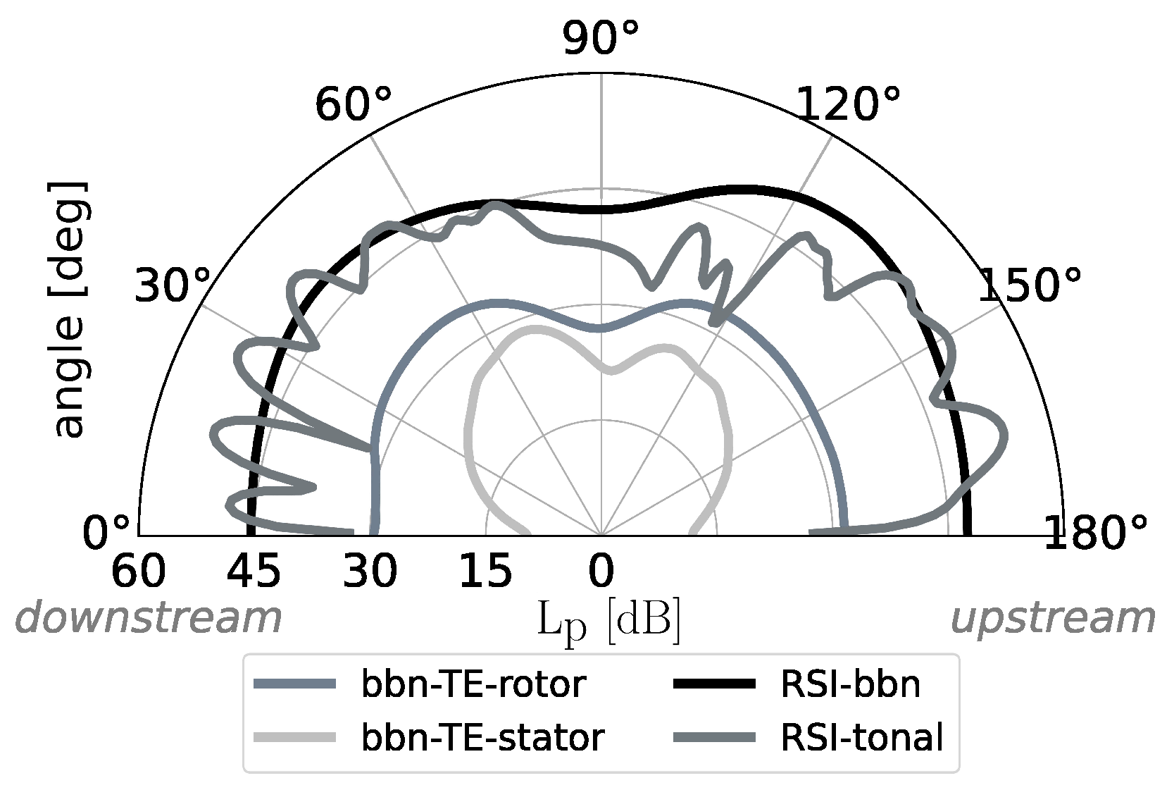
Figure 15 shows the noise directivity of the low-tone fan at design operating conditions. The noise directivity indicates that, over all radiation angles, the tonal component of the RSI noise has similar levels compared to the broadband component. For radiation angles between
and
, the tonal noise levels are even lower than the broadband levels, such that the broadband component is the dominant sound source over a wide range of radiation angles. Consequently, the noise impression of this low-speed fan is mainly characterized by broadband noise, whose energy is spread over a wide range of frequencies, and less by discrete frequencies that create tonal noise. This is particularly interesting for future listening tests, since broadband sounds are often perceived as less annoying.
As an intermediate summary, the noise emission of the low-tone fan is characterized by the following features:
The BPF1 tone is inversely cut off.
Upstream, the tonal noise excitation at the second BPF benefits from a modal propagation angle that is relatively parallel to the stator LE angle.
The dominant tonal noise radiation direction is downstream.
The tonal RSI noise is lower than the broadband component over a wide range of radiation angles.
For a possible application of this fan design in an urban air mobility airplane (e.g., a small airtaxi with a distributed propulsion system), it should be noted that this fan is equipped with a large amount of rotor and stator blades, which might increase production as well as maintenance costs. Therefore, an additional fan design with a significantly lower stator vane count is investigated in the following subsection.
5.2.3. Low-Broadband Fan: Aerodynamic Optimization and Acoustic Evaluation
The low-broadband fan is equipped with the 31-blade rotor from
Section 5.2.2 and a new 10-vane stator. Similar to the 31-blade rotor, the new stator geometry is optimized using the multi-objective optimization process described in
Section 4.4.
The generated members of the optimization and the Pareto front between the efficiency and pressure ratio for design operating conditions are shown in
Figure 16a. Again, the baseline fan is marked in purple and the low-tone fan in green. The selected member from the optimization for the 10-vane stator is marked in blue. It becomes evident that all three fan stages provide similar efficiencies and pressure ratios for design operating conditions. Thus, the aerodynamic and acoustic comparability of all three fan stages is ensured. In
Figure 16b, the geometry of the 21-vane stator is shown in detail, and its combination with the 31-blade rotor is illustrated.
Compared to the baseline fan and the low-tone fan, which both have 21 stator vanes, the number of stator vanes is approximately halved for the low-broadband fan. Due to the reduced number of stator vanes, the broadband noise is reduced significantly, as this noise source scales with the number of stator vanes [
2]. As a rule of thumb, the broadband noise is reduced by 3 dB if the number of stator vanes is halved. This is the reason why the B31V10 fan stage is named the low-broadband fan.
In order to reduce not only the broadband noise component but also the tonal component, the rotor–stator blade count of this fan stage is chosen such that the excitation of BPF1 benefits downstream from the impact of the modal propagation angle (see
Table 5). Downstream, the propagation angle of the dominantly excited mode (
) is relatively parallel to the stator leading edge angle, resulting in lower noise levels. This is confirmed by the HB simulation performed under design operating conditions and plotted in
Figure 17. The numerical results indicate a difference of 7 dB between the inter-stage and the downstream BPF1 noise levels. Consequently, the dominant noise radiation direction is upstream. Compared to the low-tone fan, which primarily emits tonal noise downstream, the low-broadband fan provides an opposing tonal radiation characteristic (see
Figure 14 and
Figure 17). Thus, both fan stages are well suited to investigate the impact of the dominant noise radiation direction on noise perception in future psychoacoustic assessments.
In line with our expectations, for the transmission through the rotor blade row, the HB simulation predicts only slight attenuation of the dominantly excited mode
(see gray triangles). This is because the mode
rotates in the rotor rotation direction. As outlined in
Section 5.2.2, for the low-tone fan, the mode
is dominantly excited, so opposing transmission behavior is expected. Therefore, both fan stages are well suited to investigate the transmission through the rotor blade row, as
rotates against the rotor rotation direction and
rotates with the rotor rotation.
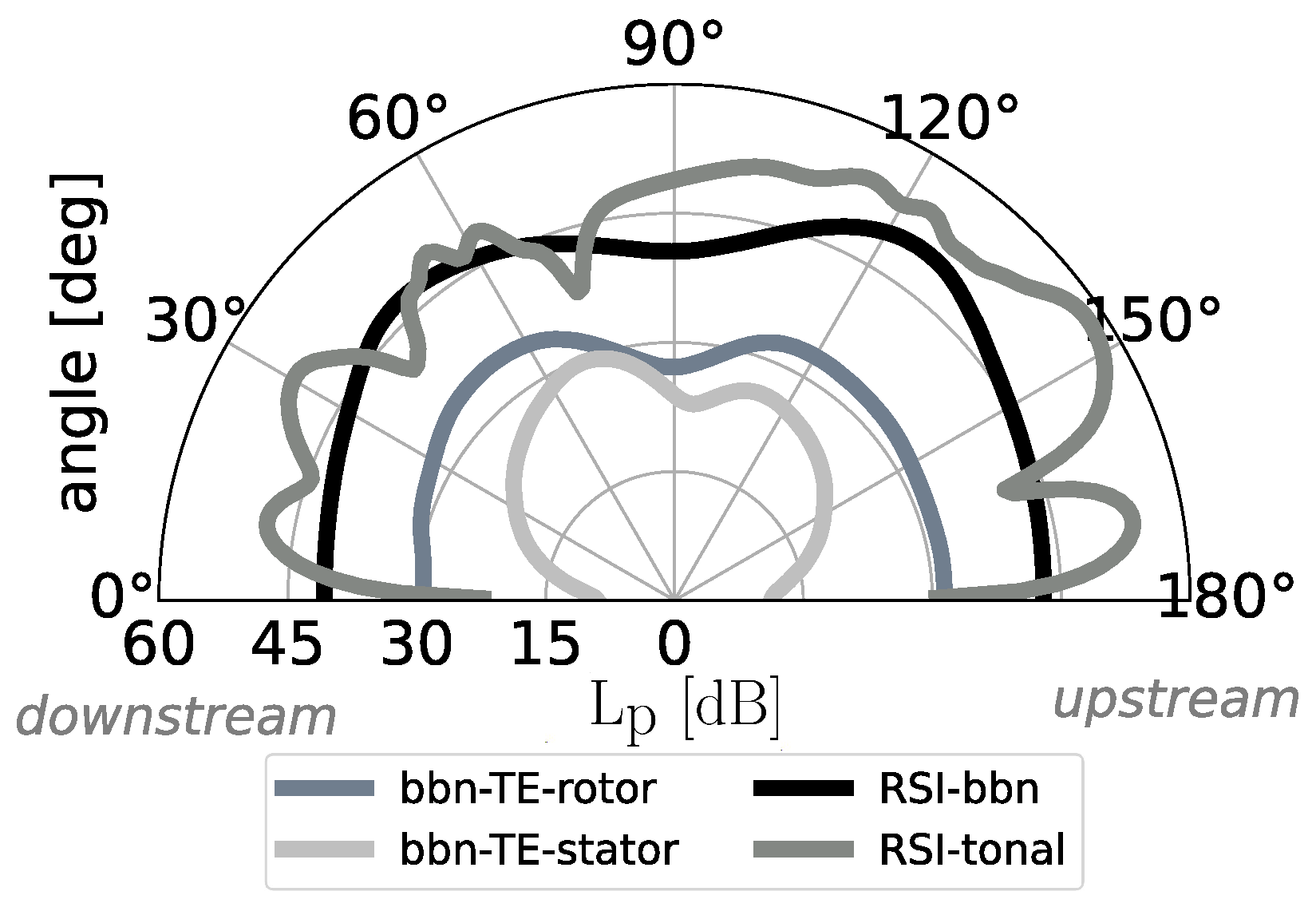
Figure 18 shows the noise directivity of the low-broadband fan at design operating conditions. The radiation characteristic of the tonal RSI noise clearly reflects the impact of the modal propagation angle. Downstream, the tonal noise levels are reduced due to the modal propagation angle, and thus, similar noise levels are observed for the tonal and broadband noise components for radiation angles between
and
. Upstream, the tonal noise levels are higher compared to the broadband levels (see radiation angles between
and
). Thus, for the low-broadband fan, tonal RSI noise is the dominant noise source over a wide range of radiation angles. In contrast, for the low-tone fan, it is observed that the broadband component is the dominant source over a wide range of radiation angles. Therefore, due to this opposing noise emission characteristic, both fan stages are well suited to investigate the impact of differences between tonal and broadband noise levels on noise perception.
As an intermediate summary, the noise emission of the low-broadband fan is characterized by the following features:
The BPF1 tone is cut-on.
Downstream, the tonal noise excitation at the first BPF benefits from a modal propagation angle that is relatively parallel to the stator LE angle.
The dominant tonal noise radiation direction is upstream.
Upstream, the tonal RSI noise is higher than the broadband component, and downstream, similar levels are predicted.
In total, as summarized in
Table 6, the baseline, low-tone and low-broadband fan stages are very similar regarding their aerodynamic characteristics. However, as illustrated in
Section 5.1,
Section 5.2.2 and
Section 5.2.3 and as summarized in
Table 7, all three fans provide opposing acoustic characteristics. In particular, the fan stages differ with regard to the dominant noise radiation direction and with regard to the ratio between tonal and broadband noise levels.
Additionally, compared to the baseline fan, for both new low-count OGV fans, the rotor blade count changes from
to
blades. Thus, as shown in
Table 7, the base frequency of the fan tones increases from 1350 Hz to 2325 Hz for the low-broadband fan and to 4650 Hz for the low-tone fan. Despite the same number of rotor blades, the low-tone fan has a higher base frequency than the low-broadband fan, as the first blade passing the frequency tone is inversely cut off. This allows us to investigate the impact of a frequency change on humans’ noise perception. Moreover, due to atmospheric absorption, higher frequencies are significantly attenuated during propagation from the noise source to an observer on the ground. This provides an additional advantage for the low-tone fan, as the higher-frequency tonal components are further attenuated while propagating through the atmosphere. All in all, as summarized in
Table 7, the fan stages are well suited to assess the acoustic criteria (a)–(c) defined in
Section 5.2.


