
An Efficient and Robust Sizing Method for eVTOL Aircraft Configurations in Conceptual Design


Abstract
:1. Introduction
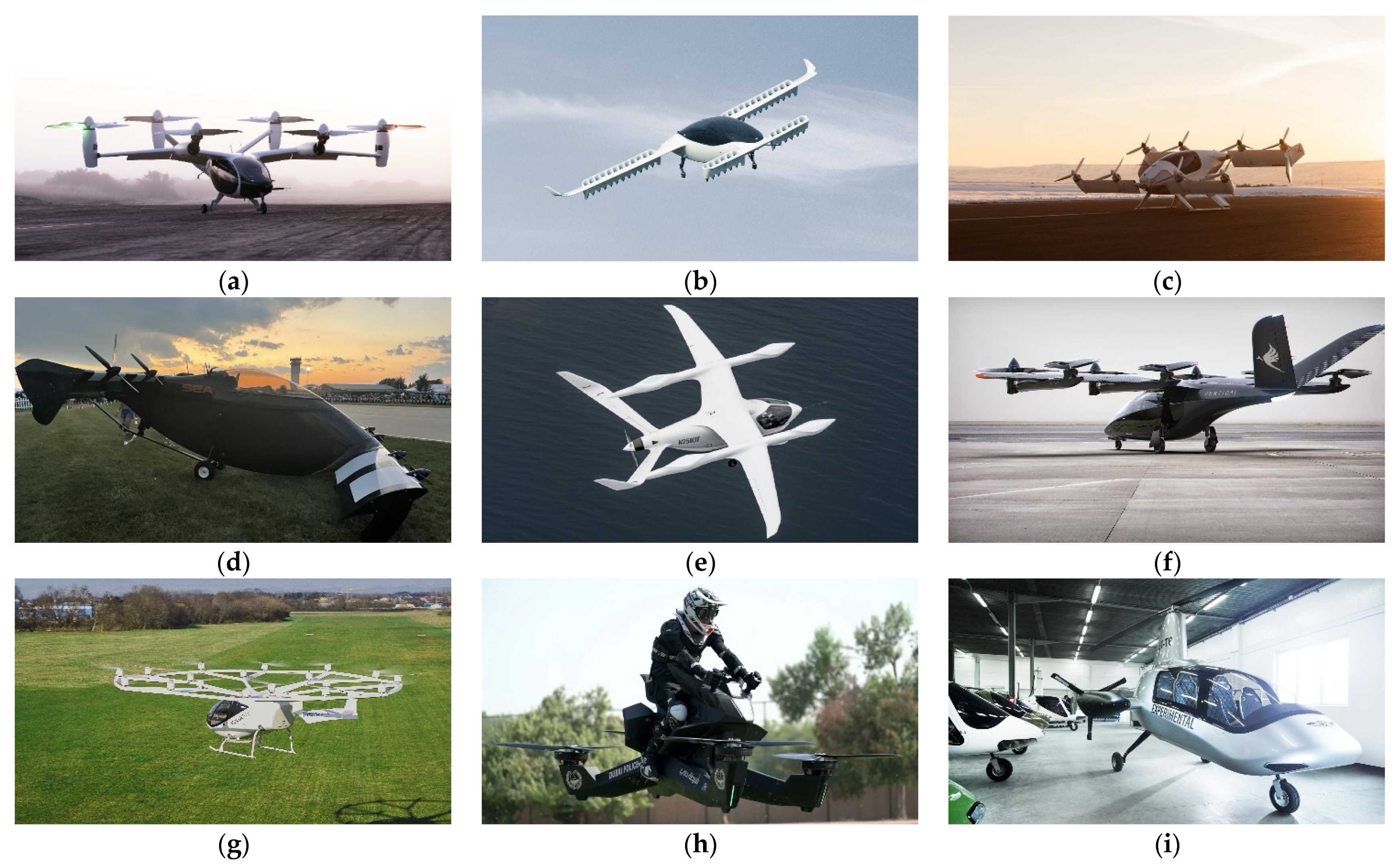
2. eVTOL Aircraft Configurations
- The inclusion of a wing and its associated systems for aerodynamic lift during the cruise stage;
- The additional LTUs required for the forward mode and, in some cases, their associated vectoring systems.

3. eVTOL Aircraft Mass Modelling
3.1. Configuration-Dependent Power Model
3.2. Energy System Mass Model
3.3. Airframe Mass Model
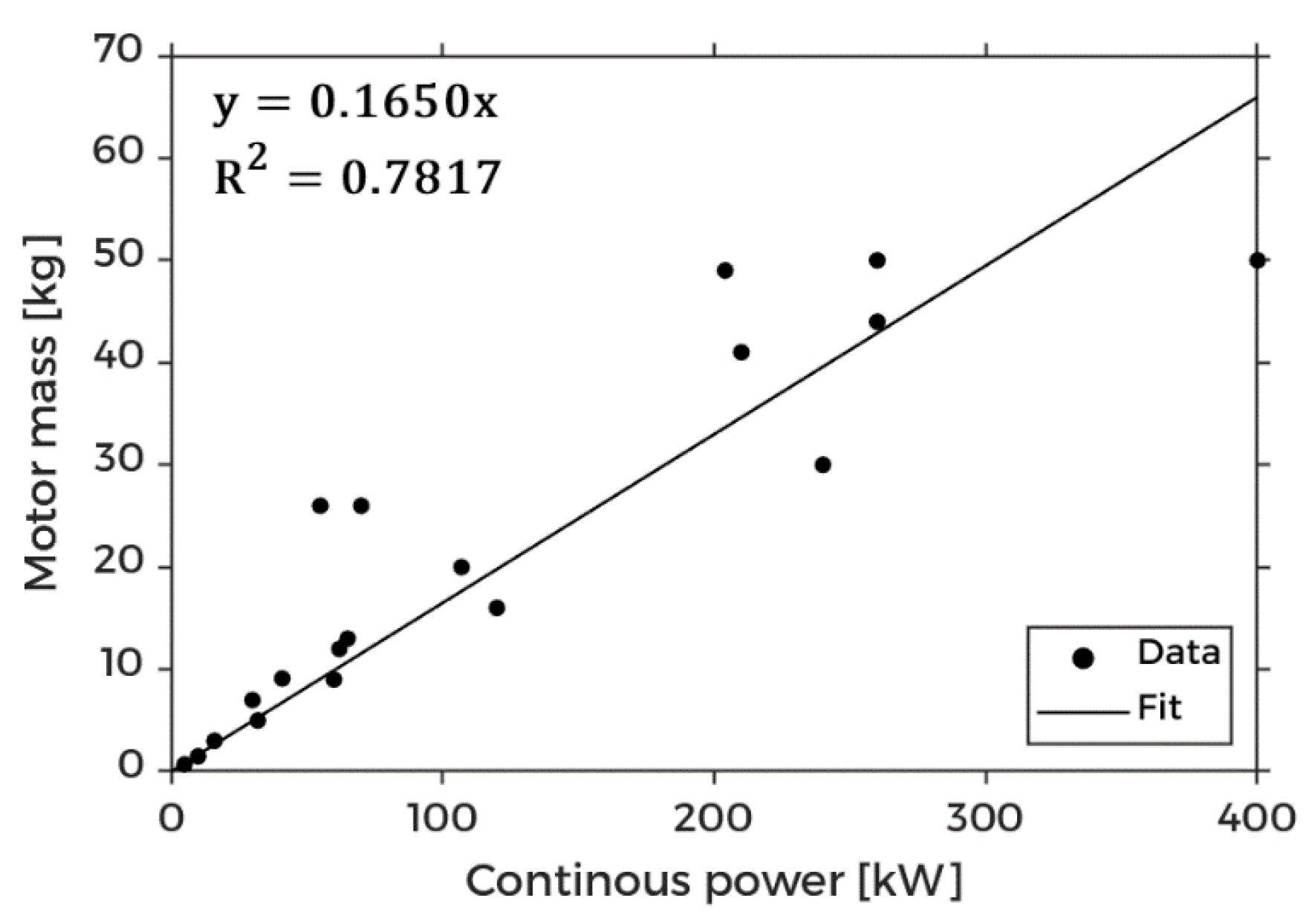
3.4. Propulsion System Mass Model
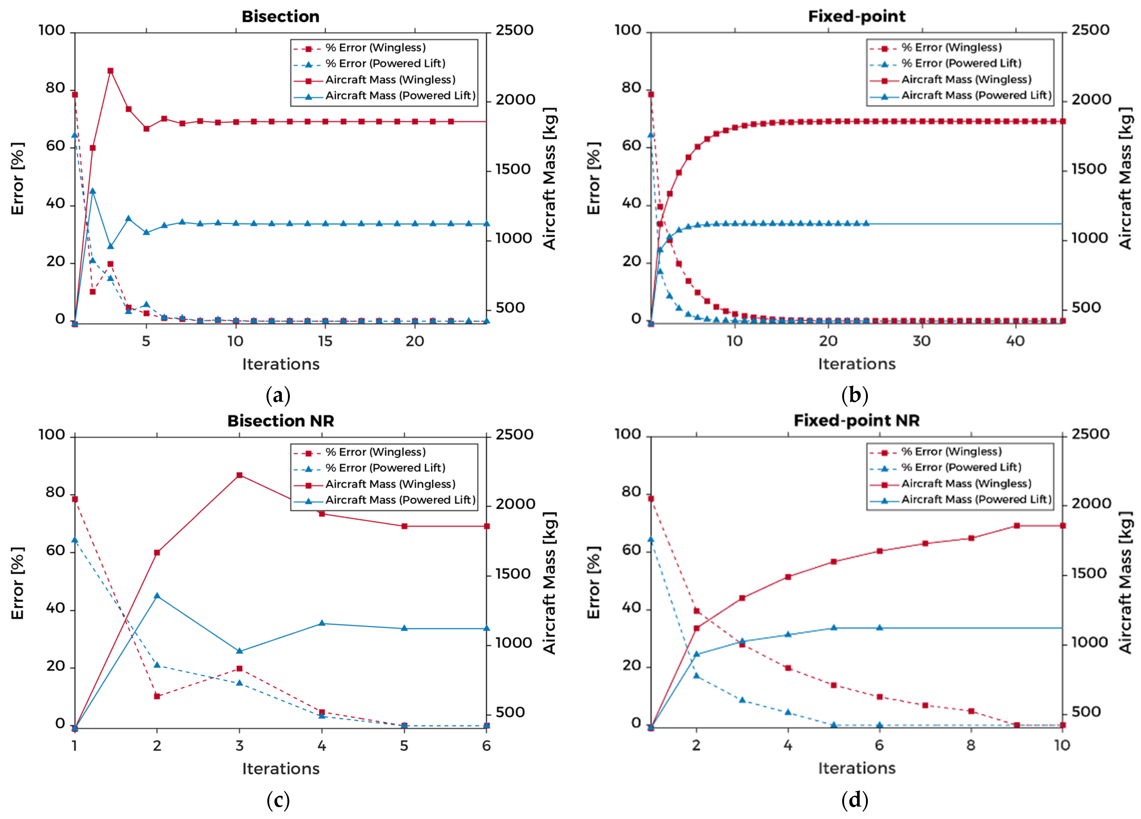
4. Sizing Method
4.1. Bisection
4.2. Fixed-Point Iteration
4.3. Newton–Raphson
4.4. Hybrid Methods
4.5. Method Evaluation
5. Sensitivity Analysis
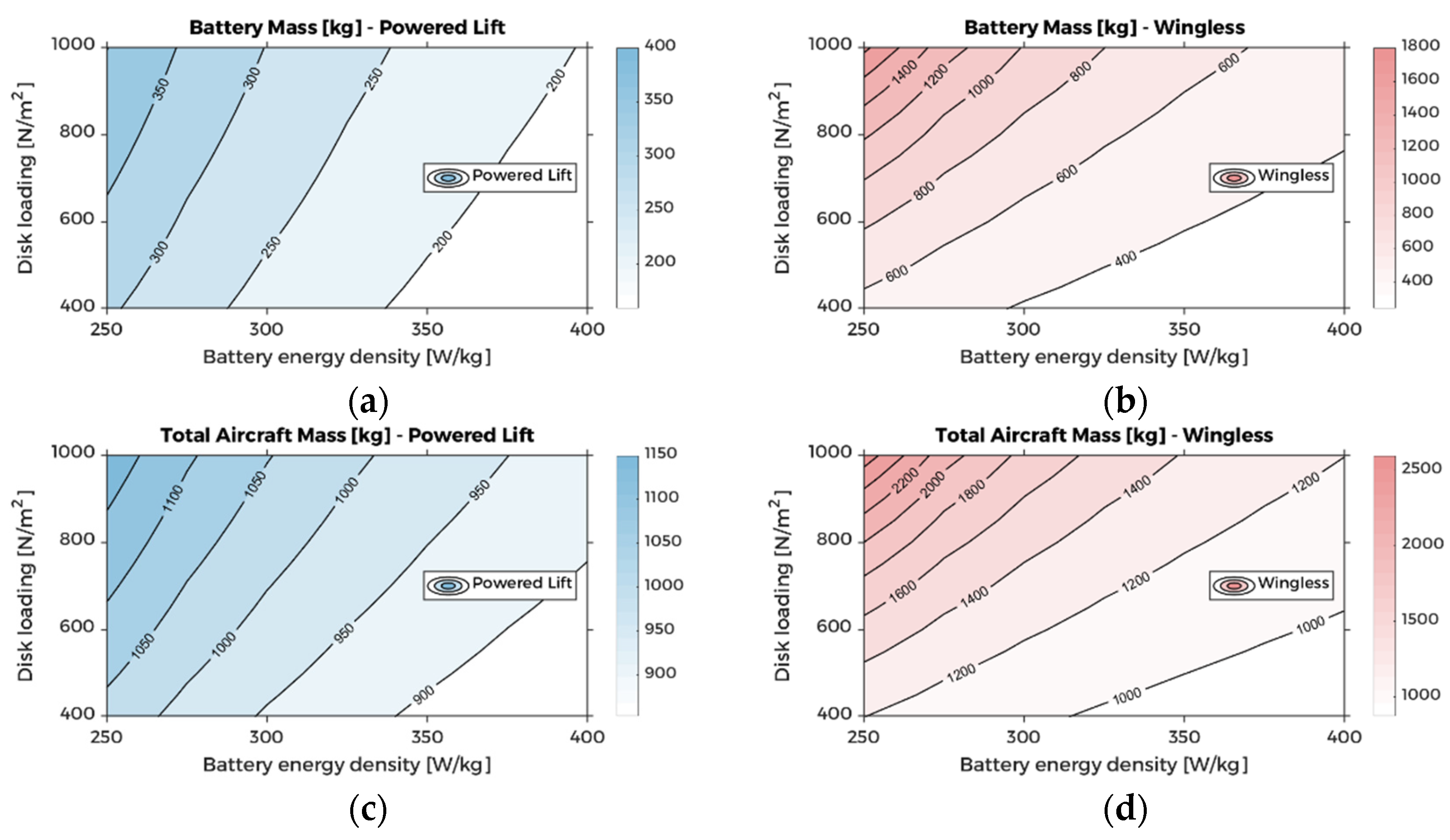
5.1. Battery Mass Considerations
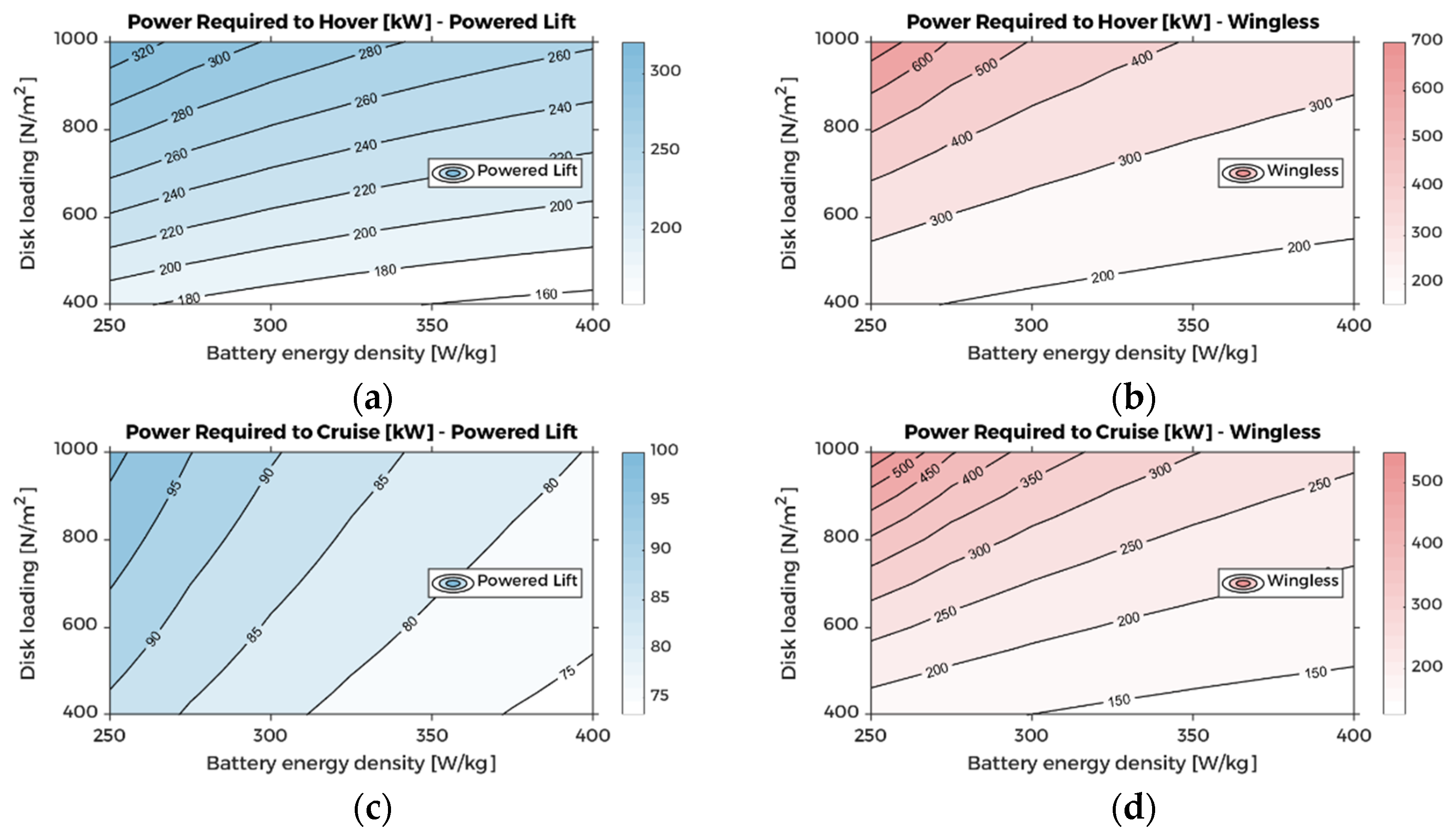
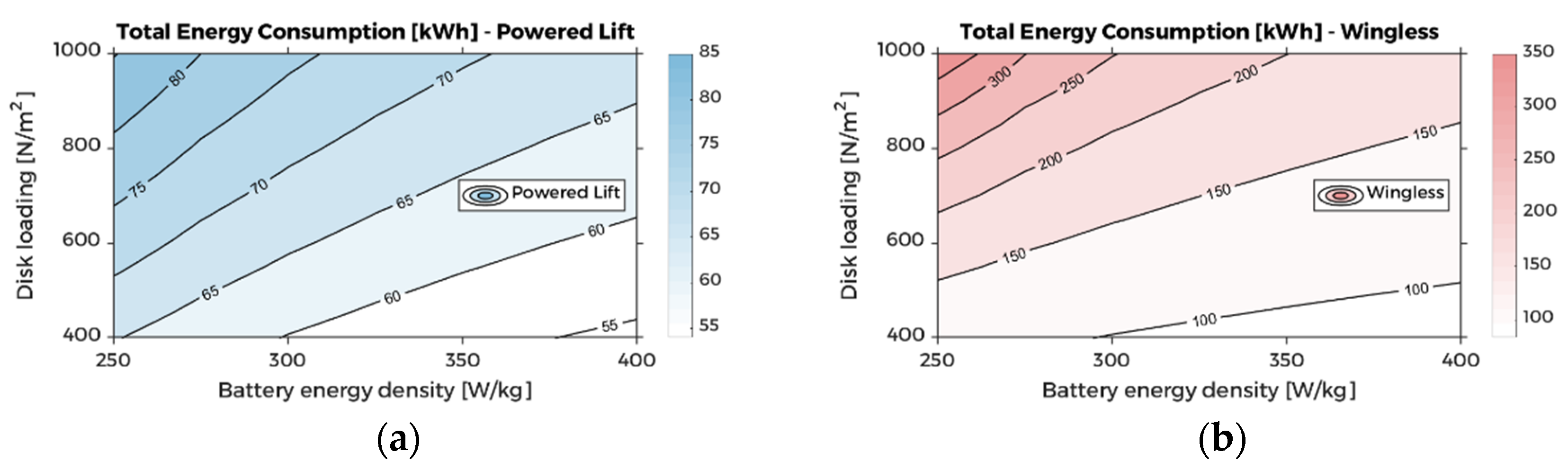
5.2. Power and Energy Considerations
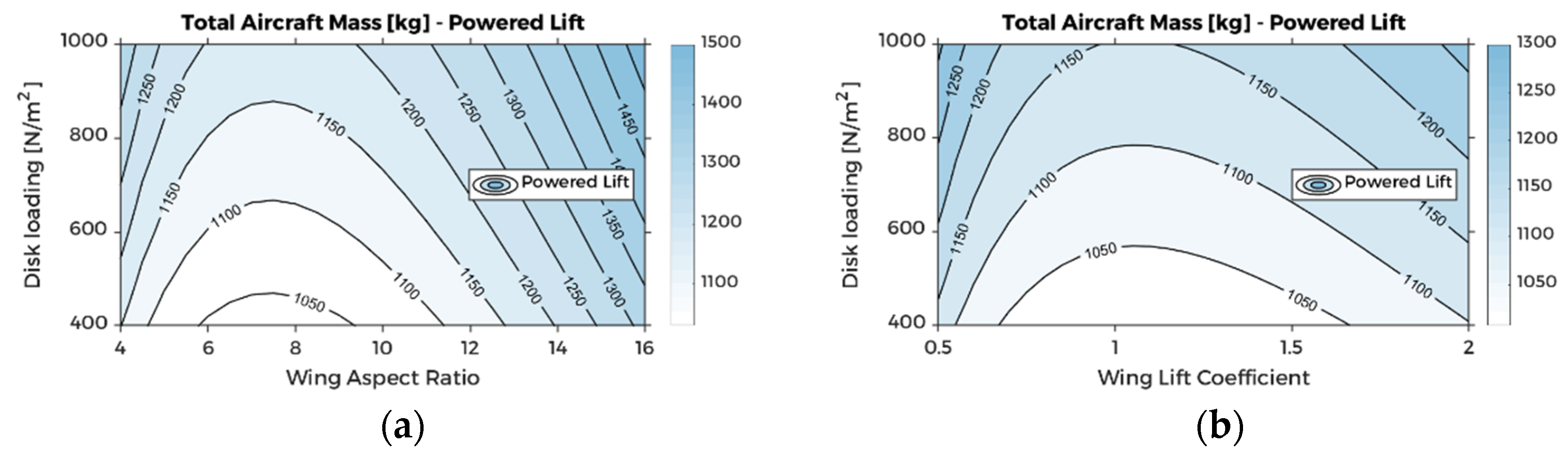
5.3. Wing Considerations
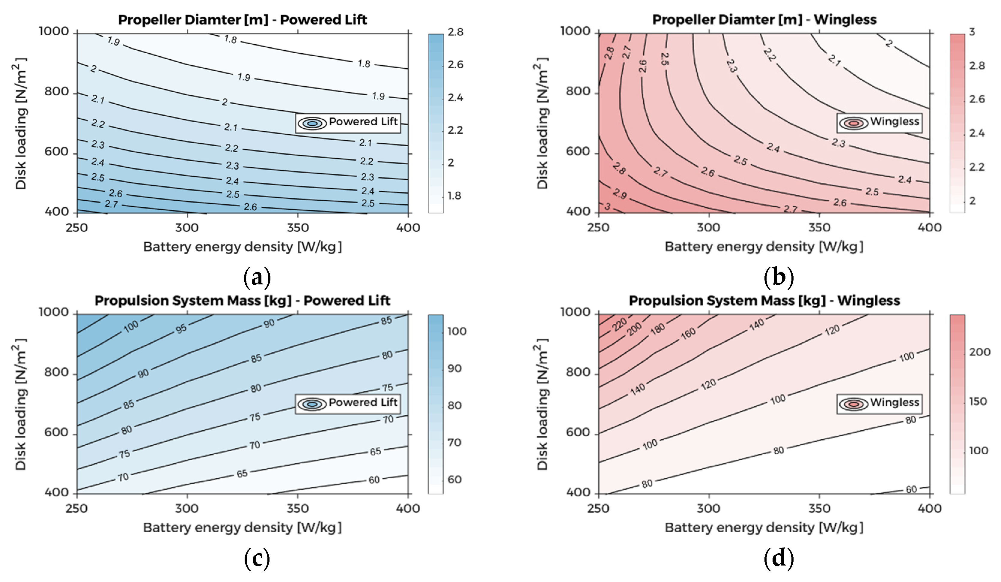
5.4. Propulsion System Mass Considerations
6. UAM Mission Analysis
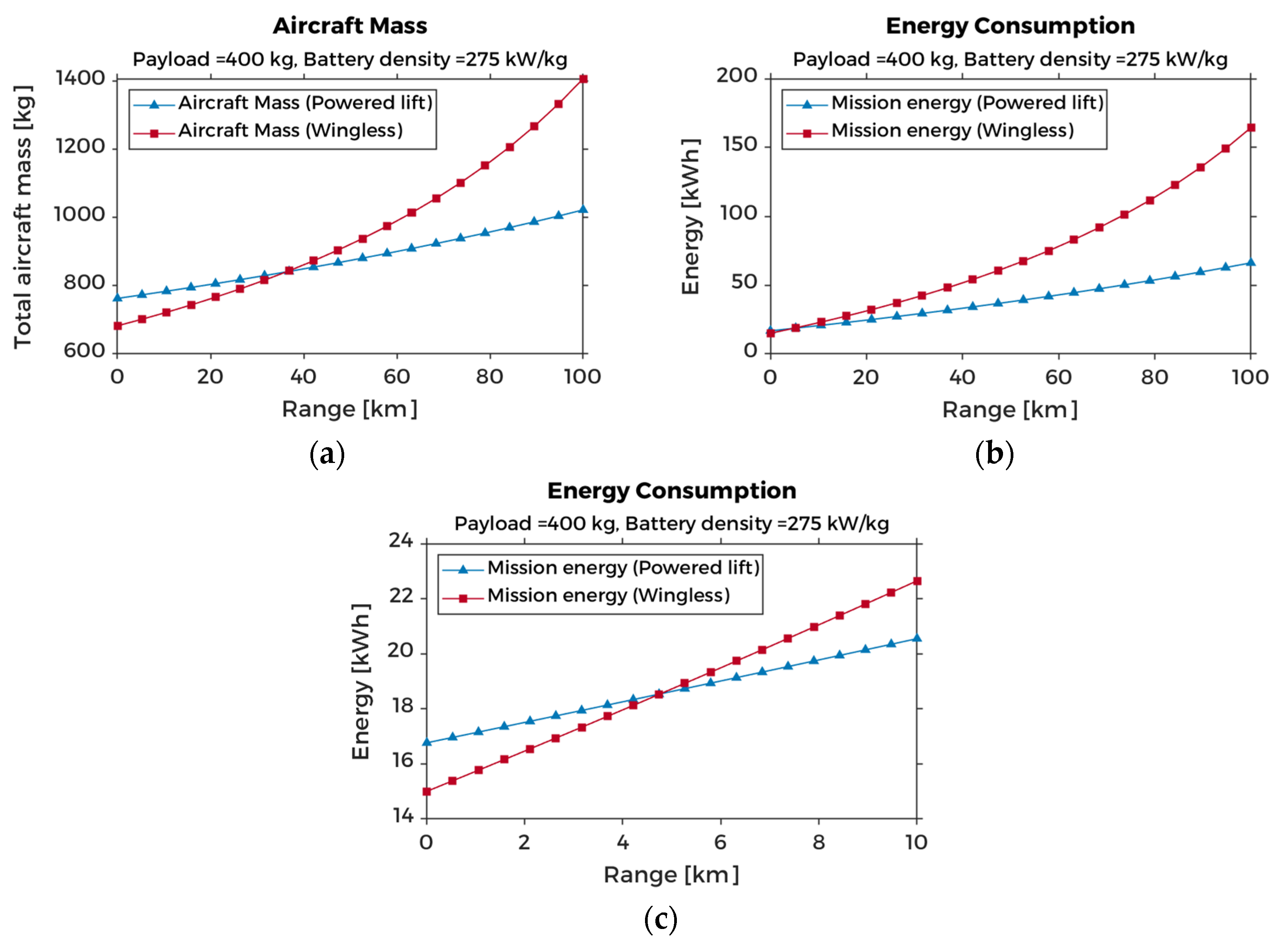
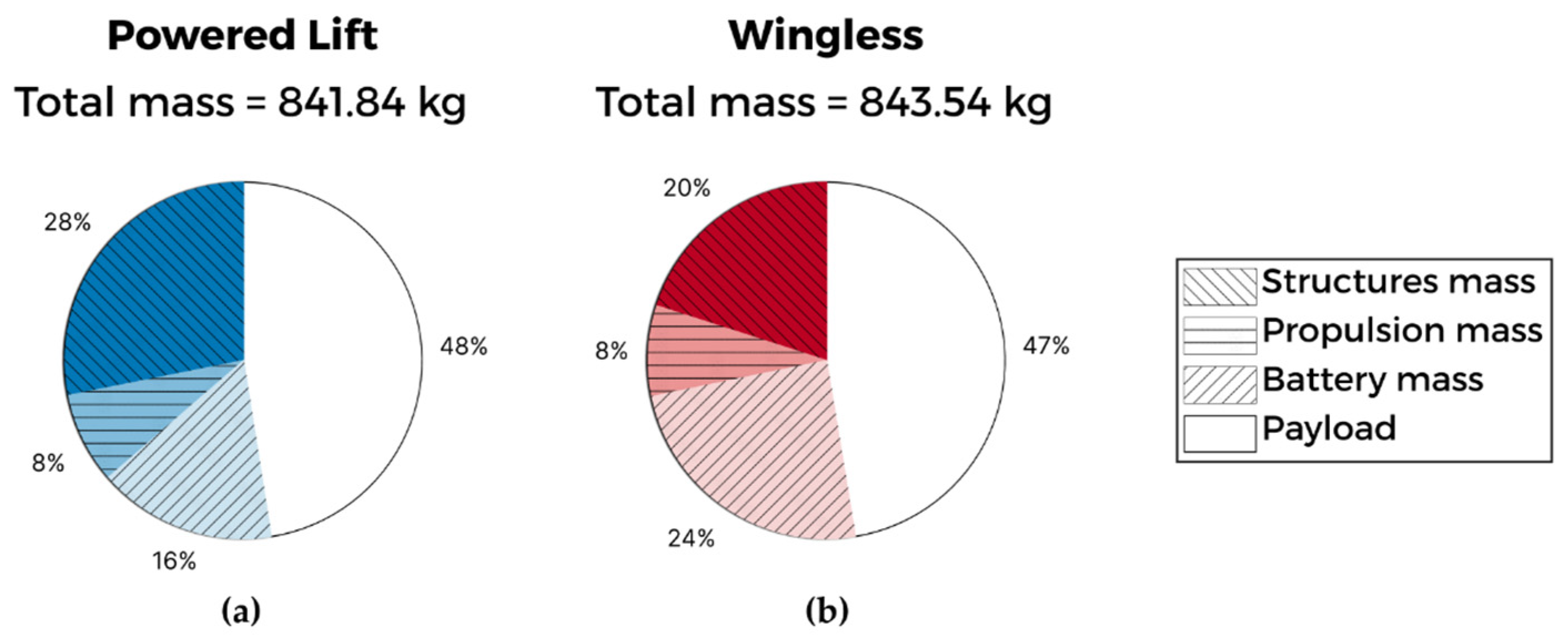
6.1. Multi-Range Mission Case
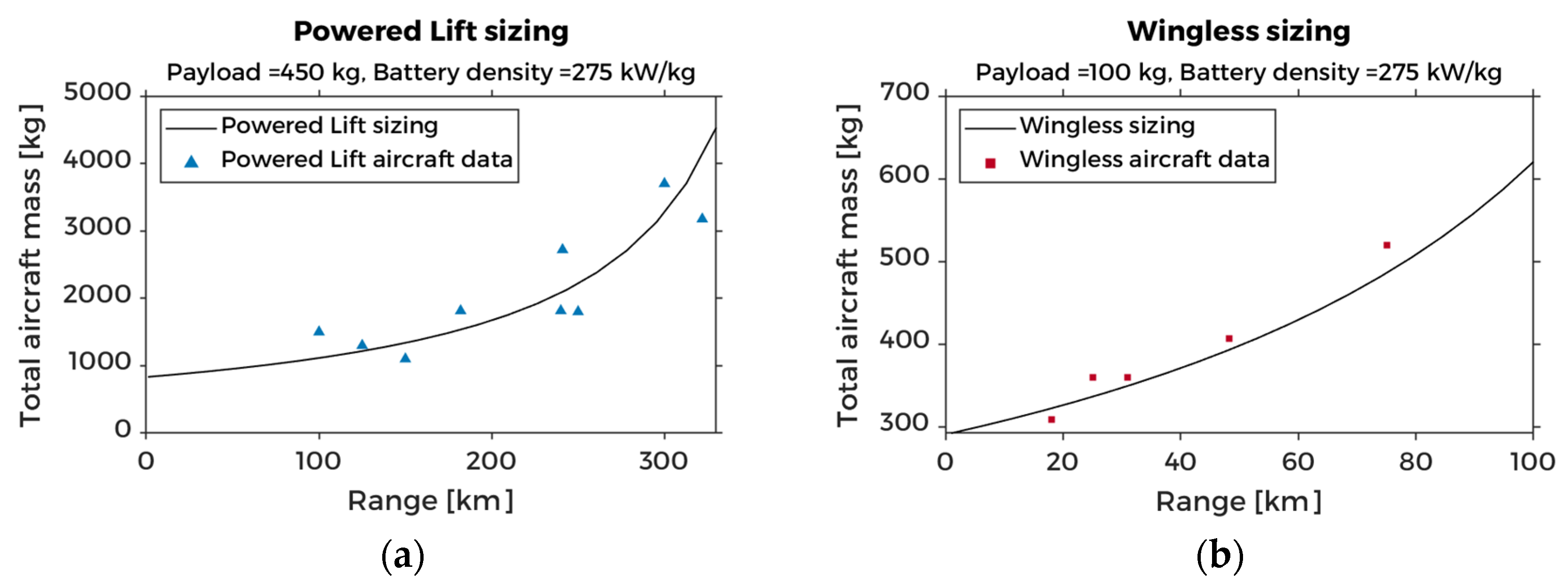
6.2. Comparison with eVTOL Aircraft Data
7. Conclusions
Author Contributions
Funding
Data Availability Statement
Conflicts of Interest
Nomenclature
| area [m2] | |
| aspect ratio | |
| drag [N] | |
| disk loading [N/m2] | |
| energy (electric) [kWh] | |
| figure of merit | |
| lift [N] | |
| number, count | |
| power [W] | |
| fuselage maximum section perimeter [m] | |
| power margin | |
| range (distance) [km] | |
| surface area [m2] | |
| specific energy density [Wh/kg] | |
| (battery) state of charge | |
| thrust [N] | |
| velocity [m/s] | |
| weight [N] | |
| quarter chord sweep angle [deg] | |
| drag coefficient | |
| lift coefficient | |
| diameter [m] | |
| Oswald’s efficiency factor | |
| length [m] | |
| mass, total mass [kg] | |
| angle of attack [deg] | |
| efficiency, design load factor | |
| (air) density [kg/m3] | |
| reserve diversion range [km] | |
| maximum tail root thickness [m] | |
| Subscripts | |
| horizontal | |
| hover | |
| battery | |
| (rotor or propeller) blade | |
| climb | |
| cruise | |
| descent | |
| fuselage | |
| landing gear | |
| maximum | |
| minimum | |
| motor | |
| propeller | |
| tail | |
| ultimate | |
| vertical | |
| wing | |
| Acronyms | |
| AAM | Advanced Air Mobility |
| DEP | Distributed Electric Propulsion |
| EASA | European Union Aviation Safety Agency |
| EPU | Electric Propulsion Unit |
| ESC | Electronic Speed Controller |
| eVTOL | electric Vertical Take-Off and Landing |
| LTU | Lift/Thrust Unit |
| NR | Newton–Raphson (method) |
| PAV | Personal Aerial Vehicle |
| PL | Powered Lift (eVTOL aircraft) |
| UAM | Urban Air Mobility |
| UAV | Uncrewed Aerial Vehicle |
| WL | Wingless (eVTOL aircraft) |
Appendix A
| Algorithm A1 Bisection NR algorithm flow |
| Inputs: |
| : Initial guess mass, lower bound, and |
| : Initial guess mass, upper bound. Must satisfy |
| : Switch-point tolerance |
| : Final tolerance |
| : Maximum iterations |
| (Bisection calculation) |
| (Initialize iteration) |
| while |
| if then |
| else |
| end if |
| if (Exact solution found using bisection) |
| return |
| else if (Switch condition) |
| while (Begin NR subroutine) |
| (Increase subroutine step) |
| (NR calculation) |
| if or (Solution found using NR) |
| return |
| end if |
| end while |
| end if |
| (Increase step) |
| end while |
| Algorithm A2 Fixed-point NR algorithm flow |
| Inputs: : Initial guess mass and : Switch-point tolerance : Final tolerance : Maximum iterations Define and such that and (Initialize iteration) while (Increase step) (Fixed-point calculation) if (Exact solution found using fixed-point) return else if (Switch condition) while (Begin NR subroutine) (Increase subroutine step) (NR calculation) if or (Solution found using NR) return end if end while end if end while |
Appendix B

| Name | Developer | Country Code (ISO2 [71]) | Primary Class | Range (km) | Payload (kg) | Mass (kg) | Source |
|---|---|---|---|---|---|---|---|
| Acubed Vahana | Airbus | US | PL | 96.6 | 204.1 | 930.0 | [54] |
| AMVA | Micor Technologies | US | PL | 125.0 | 450.0 | 1300.0 | [72] |
| EHang 184 | EHang | CN | WL | 31.0 | 100.0 | 360.0 | [73] |
| Elroy | Astro Aerospace | US | WL | 25.0 | 120.0 | 360.0 | [74] |
| Esinti | Turkish Technic | TR | WL | 48.3 | 79.8 | 406.9 | [75] |
| Flyer | Kitty Hawk | US | WL | 10.7 | 99.8 | 213.2 | [76] |
| Flyka eVTOL | Flyka | RU | WL | 75.0 | 130.0 | 520.0 | [77] |
| HEXA | LIFT Aircraft | US | WL | 18.1 | 113.4 | 309.3 | [78] |
| Joby eVTOL | Joby Aviation | US | PL | 160.9 | 90.7 | 226.8 | [51] |
| Lilium (5-seater) | Lilium | DE | PL | 250 | 500 | 1800 | [5] |
| LimoConnect | Limosa | CA | PL | 321.9 | 499.0 | 3175.1 | [79] |
| Volocopter (2-seater) | Volocopter | DE | WL | 27.4 | 158.8 | 449.1 | [57] |
| Voyager X2 | XPeng | CN | WL | 76.0 | 200.0 | 560.2 | [80] |
| VTOL | Napoleon Aero | RU | PL | 100.0 | 400.0 | 1500.0 | [81] |
Appendix C
| Motor(s) | Power (kW) | Mass (kg) | Source |
|---|---|---|---|
| Emrax 188 | 52 | 7 | [82] |
| Emrax 208 | 68 | 9.1 | [82] |
| Emrax 228 | 109 | 12 | [82] |
| Emrax 268 | 200 | 20 | [82] |
| Emrax 348 | 380 | 41 | [82] |
| MAGicALL MAGiDRIVE 12 | 12 | 1.5 | [83] |
| MAGicALL MAGiDRIVE 150 | 150 | 16 | [83] |
| MAGicALL MAGiDRIVE 20 | 20 | 3 | [83] |
| MAGicALL MAGiDRIVE 300 | 300 | 30 | [83] |
| MAGicALL MAGiDRIVE 40 | 40 | 5 | [83] |
| MAGicALL MAGiDRIVE 500 | 500 | 50 | [83] |
| MAGicALL MAGiDRIVE 6 | 6 | 0.7 | [83] |
| MAGicALL MAGiDRIVE 75 | 75 | 9 | [83] |
| Magnix magni350 EPU | 350 | 111.5 | [84] |
| Magnix magni650 EPU | 640 | 200 | [84] |
| Siemens SP200D | 204 | 49 | [85] |
| Siemens SP260D | 260 | 50 | [85] |
| Siemens SP260D-A | 260 | 44 | [85] |
| Siemens SP55D | 72 | 26 | [85] |
| Siemens SP70D | 92 | 26 | [85] |
| Siemens SP90G | 65 | 13 | [85] |
| Yuneec Power Drive 10 | 10 | 4.5 | [86] |
| Yuneec Power Drive 20 | 20 | 8.2 | [86] |
| Yuneec Power Drive 40 | 40 | 19 | [86] |
| Yuneec Power Drive 60 | 60 | 30 | [86] |
References
- Bromfield, M.A. Urban Air Mobility—Human Factors Considerations. In Proceedings of the Chartered Institute of Ergonomics & Human Factors—Human Factors in Future Transportation Conference, Birmingham, UK, 18–19 June 2018. [Google Scholar]
- Uber Elevate. Fast-Forwarding to the Future of On-Demand, Urban Air Transportation. Available online: https://www.uber.com/elevate.pdf (accessed on 22 June 2018).
- Datta, A. Commercial Intra-City On-Demand Electric-VTOL Status of Technology; AHS/NARI Transformative Vertical Flight Working Group-2, San Fransisco, CA, USA, 15 January 2018. Available online: https://vtol.org/files/dmfile/TVF.WG2.YR2017draft.pdf (accessed on 1 August 2018).
- Doo, J.T.; Pavel, M.D.; Didey, A.; Hange, C.; Diller, N.P.; Tsairides, M.A.; Smith, M.; Bennet, E.; Bromfield, M.; Mooberry, J. NASA Electric Vertical Takeoff and Landing (eVTOL) Aircraft Technology for Public Services—A White Paper; 20205000636; National Aeronautics and Space Administration: Washington, DC, USA, 1 August 2021. Available online: https://ntrs.nasa.gov/citations/20205000636 (accessed on 24 September 2022).
- Vertical Flight Society. The Electric VTOL News—eVTOL Aircraft Directory. Available online: http://evtol.news/aircraft (accessed on 12 December 2022).
- EASA. Special Condition for Small-Category Vertical Take-Off and Landing (VTOL) Aircraft; European Aviation Safety Agency: Brussels, Belgium, 2019; Volume SC-VTOL-01.
- Uber Elevate. Uber Elevate Mission and Vehicle Requirements. Available online: https://s3.amazonaws.com/uber-static/elevate/Summary+Mission+and+Requirements.pdf (accessed on 1 August 2018).
- Liu, Y.; Kreimeier, M.; Stumpf, E.; Zhou, Y.; Liu, H. Overview of recent endeavors on personal aerial vehicles: A focus on the US and Europe led research activities. Prog. Aerosp. Sci. 2017, 91, 53–66. [Google Scholar] [CrossRef]
- Yu, X.; Sandhu, N.S.; Yang, Z.; Zheng, M. Suitability of energy sources for automotive application—A review. Appl. Energy 2020, 271, 115169. [Google Scholar] [CrossRef]
- Hepperle, M. Electric Flight—Potential and Limitations; STO-MP-AVT-209; Institute of Aerodynamics and Flow Technology Braunschweig: Brunswick, Germany, 2012. Available online: https://elib.dlr.de/78726/1/MP-AVT-209-09.pdf (accessed on 1 August 2018).
- FAA; CAA. Joint FAA and United Kingdom CAA Statement on eVTOL Aircraft. Available online: https://www.faa.gov/newsroom/joint-faa-and-united-kingdom-caa-statement-evtol-aircraft (accessed on 20 May 2022).
- Roskam, J. Airplane Design—Part I: Preliminary Sizing of Airplanes; Design, Analysis and Research Corporation (DARCorporation): Lawrence, Kansas, 2018. [Google Scholar]
- Roskam, J. Airplane Design—Part II: Preliminary Configuration Design and Integration of the Propulsion System; Design, Analysis and Research Corporation (DARCorporation): Lawrence, Kansas, 2018. [Google Scholar]
- Roskam, J. Airplane Design—Part V: Component Weight Estimation; Design, Analysis and Research Corporation (DARCorporation): Lawrence, Kansas, 2018. [Google Scholar]
- Torenbeek, E. Synthesis of Subsonic Airplane Design, 1st ed.; Springer: Dordrecht, The Netherlands, 1982. [Google Scholar] [CrossRef]
- Gudmundsson, S. General Aviation Aircraft Design: Applied Methods and Procedures; Elsevier Inc.: Oxford, UK, 2014. [Google Scholar]
- Raymer, D.P. Aircraft Design: A Conceptual Approach, 4th ed.; American Institute of Aeronautics and Astronautics, Inc.: Reston, Virginia, 2006. [Google Scholar]
- Newman, S. The foundations of Helicopter Flight; Butterworth Heinemann: Oxford, UK; Burlington, MA, Canada, 2003. [Google Scholar]
- Newman, J.S.S. Basic Helicopter Aerodynamics, 3rd ed.; John Wiley & Sons, Ltd.: Chichester, UK, 2011. [Google Scholar] [CrossRef]
- Johnson, W. Helicopter Theory; Dover Publications, Inc.: New York, NY, USA, 1980. [Google Scholar]
- Prouty, R.W. Helicopter Performance, Stability, and Control; Robert, E., Ed.; Krieger Publishing Company: Malabar, FL, USA, 1990. [Google Scholar]
- Leishman, J.G. Principles of Helicopter Aerodynamics, 2nd ed.; Cambridge University Press: New York, NY, USA, 2006. [Google Scholar]
- Palaia, G.; Zanetti, D.; Abu Salem, K.; Cipolla, V.; Binante, V. THEA-CODE: A design tool for the conceptual design of hybrid-electric aircraft with conventional or unconventional airframe configurations. Mech. Ind. 2021, 22, 19. [Google Scholar] [CrossRef]
- Bacchini, A.; Cestino, E.; Van Magill, B.; Verstraete, D. Impact of lift propeller drag on the performance of eVTOL lift+cruise aircraft. Aerosp. Sci. Technol. 2021, 109, 106429. [Google Scholar] [CrossRef]
- Brown, A.; Harris, W.L. Vehicle Design and Optimization Model for Urban Air Mobility. J. Aircr. 2020, 57, 1003–1013. [Google Scholar] [CrossRef]
- Palaia, G.; Abu Salem, K.; Cipolla, V.; Binante, V.; Zanetti, D. A Conceptual Design Methodology for e-VTOL Aircraft for Urban Air Mobility. Appl. Sci. 2021, 11, 10815. [Google Scholar] [CrossRef]
- Chauhan, S.S.; Martins, J.R.R.A. Tilt-Wing eVTOL Takeoff Trajectory Optimization. J. Aircr. 2020, 57, 93–112. [Google Scholar] [CrossRef]
- Riboldi, C.E.D.; Gualdoni, F.; Trainelli, L. Preliminary weight sizing of light pure-electric and hybrid-electric aircraft. Transp. Res. Procedia 2018, 29, 376–389. [Google Scholar] [CrossRef]
- Tyan, M.; Nguyen, N.V.; Kim, S.; Lee, J.-W. Comprehensive preliminary sizing/resizing method for a fixed wing—VTOL electric UAV. Aerosp. Sci. Technol. 2017, 71, 30–41. [Google Scholar] [CrossRef]
- Lee, B.-S.; Tullu, A.; Hwang, H.-Y. Optimal Design and Design Parameter Sensitivity Analyses of an eVTOL PAV in the Conceptual Design Phase. Appl. Sci. 2020, 10, 5112. [Google Scholar] [CrossRef]
- An, J.-H.; Kwon, D.-Y.; Jeon, K.-S.; Tyan, M.; Lee, J.-W. Advanced Sizing Methodology for a Multi-Mode eVTOL UAV Powered by a Hydrogen Fuel Cell and Battery. Aerospace 2022, 9, 71. [Google Scholar] [CrossRef]
- Govindarajan, B.; Sridharan, A. Conceptual Sizing of Vertical Lift Package Delivery Platforms. J. Aircr. 2020, 57, 1170–1188. [Google Scholar] [CrossRef]
- Ugwueze, O.; Statheros, T.; Horri, N.; Innocente, M.; Bromfield, M. Investigation of a Mission-based Sizing Method for Electric VTOL Aircraft Preliminary Design. In Proceedings of the AIAA SCITECH 2022 Forum, San Diego, CA, USA, 3–7 January 2022. [Google Scholar] [CrossRef]
- Bacchini, A.; Cestino, E. Electric VTOL Configurations Comparison. Aerospace 2019, 6, 26. [Google Scholar] [CrossRef] [Green Version]
- Vries, R.d.; Brown, M.T.; Vos, R. A Preliminary Sizing Method for Hybrid-Electric Aircraft Including Aero-Propulsive Interaction Effects. In Proceedings of the Aviation Technology, Integration, and Operations Conference, Atlanta, Georgia, 25–29 June 2018. [Google Scholar] [CrossRef]
- Finger, D.F.; Bil, C.; Braun, C. Initial Sizing Methodology for Hybrid-Electric General Aviation Aircraft. J. Aircr. 2020, 57, 245–255. [Google Scholar] [CrossRef]
- Kamal, A.M.; Alex, R.-S. Design methodology for hybrid (VTOL + Fixed Wing) unmanned aerial vehicles. Aeron. Aero. Open Access J. 2018, 2, 165–176. [Google Scholar] [CrossRef] [Green Version]
- Bacchini, A.; Cestino, E. Key aspects of electric vertical take-off and landing conceptual design. Proc. Inst. Mech. Eng. Part G J. Aerosp. Eng. 2020, 234, 774–787. [Google Scholar] [CrossRef]
- Barra, F.; Capone, P.; Guglieri, G. A Methodology for Preliminary Performance Estimation of a Hybrid-Electric Tilt-Wing Aircraft for Emergency Medical Services. In Proceedings of the 2020 International Conference on Unmanned Aircraft Systems (ICUAS), Athens, Greece, 1–4 September 2020; pp. 1636–1643. [Google Scholar] [CrossRef]
- Cakin, U.; Kaçan, Z.; Aydogan, Z.A.; Kuvvetli, I. Initial Sizing of Hybrid Electric VTOL Aircraft for Intercity Urban Air Mobility. In Proceedings of the AIAA Aviation 2020 Forum, Virtual Event, 15–19 June 2020. [Google Scholar] [CrossRef]
- Sripad, S.; Viswanathan, V. The promise of energy-efficient battery-powered urban aircraft. Proc. Natl. Acad. Sci. USA 2021, 118, e2111164118. [Google Scholar] [CrossRef]
- Yin, F.; Jin, Q.; Gao, H.; Zhang, X.; Zhang, Z. A strategy to achieve high loading and high energy density Li-S batteries. J. Energy Chem. 2021, 53, 340–346. [Google Scholar] [CrossRef]
- Kadhiresan, A.R.; Duffy, M.J. Conceptual Design and Mission Analysis for eVTOL Urban Air Mobility Flight Vehicle Configurations. In AIAA Aviation 2019 Forum; American Institute of Aeronautics and Astronautics: Dallas, TX, USA, 2019. [Google Scholar] [CrossRef]
- Hascaryo, R.W.; Merret, J.M. Configuration-Independent Initial Sizing Method for UAM/eVTOL Vehicles. In AIAA AVIATION FORUM; American Institute of Aeronautics and Astronautics: Dallas, TX, USA, 2020. [Google Scholar] [CrossRef]
- Stoll, A.M.; Bevirt, J.; Pei, P.P.; Stilson, V.E. Conceptual Design of the Joby S2 Electric VTOL PAV. In Proceedings of the Aviation Technology, Integration and Operations Conference, Atlanta, GA, USA, 16–20 June 2014. [Google Scholar]
- Brown, A.; Harris, W. A Vehicle Design and Optimization Model for On-Demand Aviation. In 2018 AIAA/ASCE/AHS/ASC Structures, Structural Dynamics, and Materials Conference; American Institute of Aeronautics and Astronautics: Kissimmee, FL, USA, 2018. [Google Scholar] [CrossRef] [Green Version]
- EVE Air Mobility. Mobility Reimagined. Available online: https://eveairmobility.com (accessed on 9 May 2022).
- Howard, C.E. Uber Unveils Third eVTOL Common Reference Model Concept for Future Flying Taxis. Available online: https://www.militaryaerospace.com/commercial-aerospace/article/14229631/uber-unveils-third-evtol-common-reference-model-concept-for-future-flying-taxis (accessed on 9 May 2022).
- AFRPS. Introduction to V/STOL Technology; USAF Aerospace Research Pilot School: Edwards, CA, USA, 1970. [Google Scholar]
- Lilium. Lilium Jet—The First Electric VTOL (eVTOL) Jet. Available online: https://lilium.com/jet (accessed on 12 November 2022).
- Joby Aviation. Joby. Available online: https://www.jobyaviation.com (accessed on 12 November 2022).
- FutureFlight. Neoptera Aero eOpter—Complete Performance Data. Available online: https://www.futureflight.aero/aircraft-program/eopter (accessed on 9 May 2022).
- Opener Aero. Blackfly. Available online: https://opener.aero (accessed on 12 November 2022).
- Airbus. A3 Vahana (1-Seater). Available online: https://acubed.airbus.com/projects/vahana (accessed on 24 December 2019).
- BETA Technologies. The Future of Flight. Available online: https://www.beta.team (accessed on 12 November 2022).
- Vertical Aerospace. VX4—Urban Air Mobility—Vertical Aerospace. Available online: https://vertical-aerospace.com/vx4 (accessed on 9 May 2022).
- Volocopter. Volocopter. Available online: https://www.volocopter.com (accessed on 30 November 2022).
- Hoversurf. The Idea Is Freedom. Available online: https://www.hoversurf.com/ (accessed on 12 November 2022).
- Aviation Artur Trendak. T6—Prototype. Available online: https://trendak.eu/pl/modele/t6-prototyp/ (accessed on 12 November 2022).
- Liu, R.-L.; Zhang, Z.-J.; Jiao, Y.-F.; Yang, C.-H.; Zhang, W.-J. Study on Flight Performance of Propeller-Driven UAV. Int. J. Aerosp. Eng. 2019, 2019, 6282451. [Google Scholar] [CrossRef] [Green Version]
- NASA. Vehicle Sketch Pad (VSP): Geometric Modeling Software to Support Aircraft Conceptual Design, 3.24.0; National Aeronautics and Space Administration: Hampton, Virginia, 2021.
- McDonald, R.A.; Gloudemans, J.R. Open Vehicle Sketch Pad: An Open Source Parametric Geometry and Analysis Tool for Conceptual Aircraft Design. In Proceedings of the AIAA SCITECH 2022 Forum, San Diego, CA, USA, 3–7 January 2022. [Google Scholar] [CrossRef]
- Archer, C.L.; Caldeira, K. Global Assessment of High-Altitude Wind Power. Energies 2009, 2, 307–319. [Google Scholar] [CrossRef] [Green Version]
- Stojakovic, P.; Rasuo, B. Single propeller airplane minimal flight speed based upon the lateral maneuver condition. Aerosp. Sci. Technol. 2016, 49, 239–249. [Google Scholar] [CrossRef]
- Stojaković, P.; Velimirović, K.; Rašuo, B. Power optimization of a single propeller airplane take-off run on the basis of lateral maneuver limitations. Aerosp. Sci. Technol. 2018, 72, 553–563. [Google Scholar] [CrossRef]
- Zhao, S.; Guo, Z.; Yan, K.; Wan, S.; He, F.; Sun, B.; Wang, G. Towards high-energy-density lithium-ion batteries: Strategies for developing high-capacity lithium-rich cathode materials. Energy Storage Mater. 2021, 34, 716–734. [Google Scholar] [CrossRef]
- Adu-Gyamfi, B.A.; Good, C. Electric aviation: A review of concepts and enabling technologies. Transp. Eng. 2022, 9, 100134. [Google Scholar] [CrossRef]
- Sholz, D. Empennage sizing with the tail volume complemented with a method for dorsal fin layout. INCAS Bull. 2021, 13, 149–164. [Google Scholar] [CrossRef]
- Chapra, S.C.; Canale, R.P. Numerical Methods for Engineers, 2nd ed.; McGraw-Hill: New York, NY, USA, 1990; p. 812. [Google Scholar]
- Martins, J.R.R.A.; Ning, A. Engineering Design Optimization; Cambridge University Press: Cambridge, UK, 2021. [Google Scholar] [CrossRef]
- International Organization for Standardization. ISO 3166—Country Codes. Available online: https://www.iso.org/iso-3166-country-codes.html (accessed on 1 August 2022).
- Micor Technologies. AMVA. Available online: https://micortec.com (accessed on 12 November 2022).
- EHang. UAM—Passenger Autonomous Aerial Vehicle (AAV). Available online: https://www.ehang.com/ehangaav (accessed on 12 November 2022).
- Astro Aerospace. The Future Is Here. Available online: https://flyastro.com (accessed on 12 November 2022).
- Turkish Technic. Esinti. Available online: https://turkishtechnic.com (accessed on 12 November 2022).
- Wisk Aero. Autonomous Urban Air Mobility. Available online: https://wisk.aero/aircraft (accessed on 30 November 2022).
- Flyka Aero. eVTOL Aircraft, Unmanned & Safe. Available online: https://flyka.aero (accessed on 12 November 2022).
- Lift Aircraft. Hexa eVTOL. Available online: https://www.embention.com/projects/hexa-evtol/ (accessed on 12 November 2022).
- Limosa. LimoConnect. Available online: https://limosa.ca (accessed on 12 November 2022).
- Xpeng. Voyager X2. Available online: https://www.aeroht.com (accessed on 12 November 2022).
- Napoleon Aero. VTOL. Available online: https://iz.ru/677018/sergei-valchenko/taksi-s-vertikalnym-vzletom (accessed on 9 May 2021).
- EMRAX. EMRAX Electric Motors/Generators. Available online: https://emrax.com/e-motors/ (accessed on 26 September 2022).
- MAGicALL. Magnetic Components & Electronic Systems—Products. Available online: https://www.magicall.biz/products/ (accessed on 26 September 2022).
- magniX. Industry-Leading Electric Propulsion Systems. Available online: https://www.magnix.aero/services (accessed on 26 September 2022).
- Siemens eAircraft. Disrupting the Way You Will Fly! Available online: https://www.ie-net.be/sites/default/files/Siemens%20eAircraft%20-%20Disrupting%20Aircraft%20Propulsion%20-%20OO%20JH%20THO%20-%2020180427.cleaned.pdf (accessed on 26 September 2022).
- Yuneec. Power Systems. Available online: http://www.yuneec.com/PowerMotor_Tech_spec.html (accessed on 26 September 2022).


| Mission Phase | eVTOL Configuration | Power Model | |
|---|---|---|---|
| 1 | Take-off, Hover | Both | |
| 2 | Climb | Both | |
| 3a | Cruise | Powered lift | |
| 3b | Cruise | Wingless | |
| 4 | Descent | Both | Only valid for higher descent speeds (). For lower descent speeds (), the assumption applies. |
| 5 | Landing, Hover | Both | The same as Take-off, Hover |
| Design Parameter | Value | Applies to |
|---|---|---|
| Payload | 400 kg | Both |
| 4 | Both | |
| 0.75 | Both | |
| 0.04353 | Powered lift | |
| 0.04476 | Wingless | |
| 0.85 | Both | |
| 4 | Both | |
| 50% | Both | |
| 20% | Both | |
| 250 Wh/kg | Both | |
| 0.85 | Both | |
| 1.5 | Powered lift | |
| 7.0 | Powered lift | |
| 0.85 | Powered lift | |
| 5.0 m | Both | |
| 4.71 m | Both |
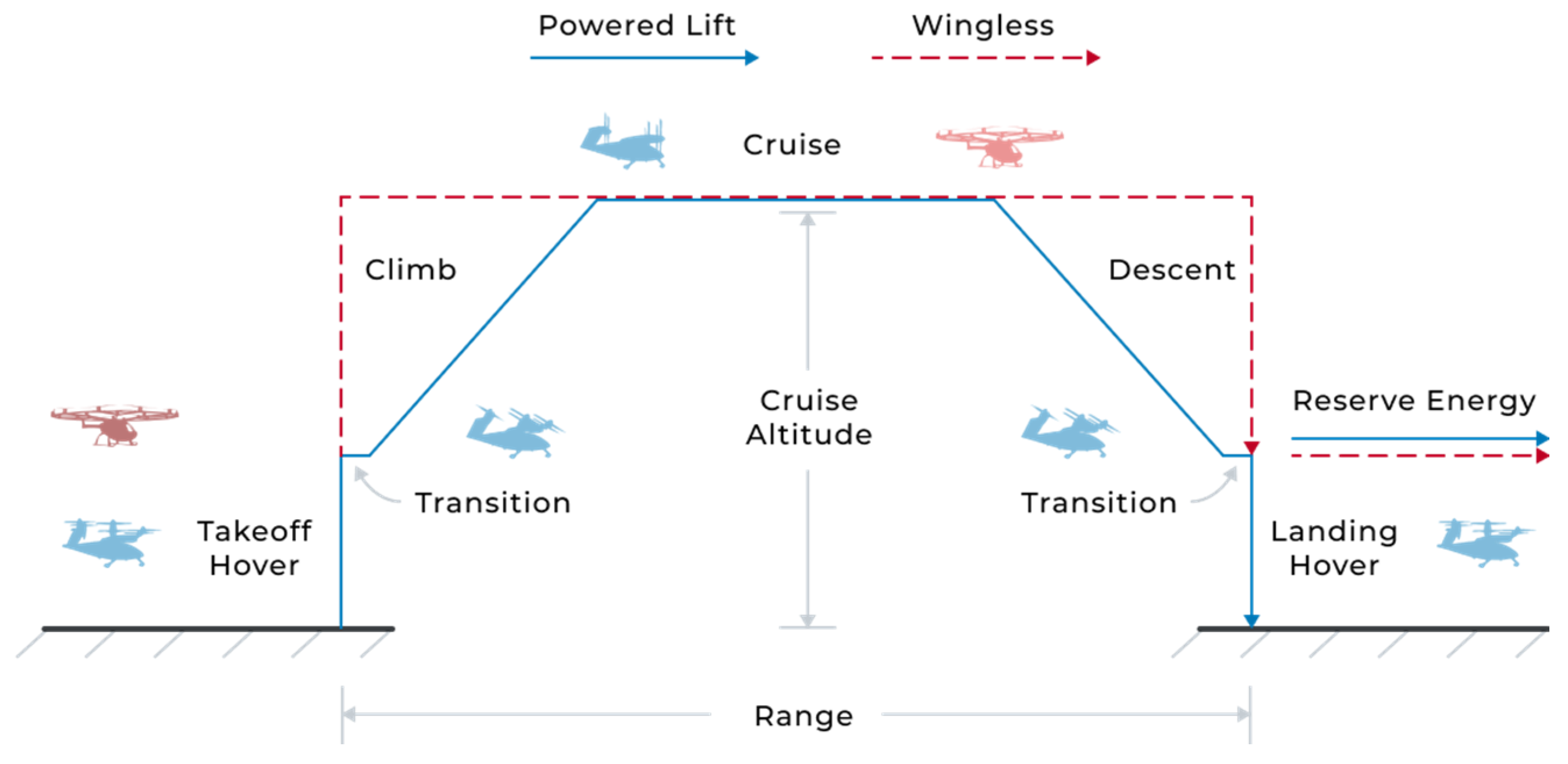
| Mission Phase | Duration (min) | Horizontal Speed (km/h) | Distance (km) | Vertical Speed (m/min) | Ending Altitude (m) |
|---|---|---|---|---|---|
| Take-off Hover | 0.17 | 0 | 0 | 0 | 1.5 |
| Climb | 2 | 0 | 0 | 150 | 300 |
| Cruise | 25 | 240 | 100 | 0 | 300 |
| Descent | 2 | 0 | 0 | −150 | 1.5 |
| Landing Hover | 0.17 | 0 | 0 | 0 | 0 |
| Convergence | Bisection | Fixed-Point | Bisection NR | Fixed-Point NR |
|---|---|---|---|---|
| Average number of iterations | 23 | 35 | 6 | 8 |
| Relative compute time | 1 | 0.67 | 0.27 | 0.22 |
| Airframe Component Masses | Powered Lift (kg) | Wingless (kg) | |
|---|---|---|---|
| Fuselage | 156.97 | 157.01 | 0.03 |
| Wing | 54.99 | - | - |
| Horizontal stabiliser | 11.8 | - | - |
| Vertical stabiliser | 1.22 | - | - |
| Landing gear | 11.90 | 11.92 | 0.14 |
| Total airframe mass | 236.88 | 168.93 | 28.69 |
Disclaimer/Publisher’s Note: The statements, opinions and data contained in all publications are solely those of the individual author(s) and contributor(s) and not of MDPI and/or the editor(s). MDPI and/or the editor(s) disclaim responsibility for any injury to people or property resulting from any ideas, methods, instructions or products referred to in the content. |
© 2023 by the authors. Licensee MDPI, Basel, Switzerland. This article is an open access article distributed under the terms and conditions of the Creative Commons Attribution (CC BY) license (https://creativecommons.org/licenses/by/4.0/).
Share and Cite
Ugwueze, O.; Statheros, T.; Horri, N.; Bromfield, M.A.; Simo, J. An Efficient and Robust Sizing Method for eVTOL Aircraft Configurations in Conceptual Design. Aerospace 2023, 10, 311. https://doi.org/10.3390/aerospace10030311
Ugwueze O, Statheros T, Horri N, Bromfield MA, Simo J. An Efficient and Robust Sizing Method for eVTOL Aircraft Configurations in Conceptual Design. Aerospace. 2023; 10(3):311. https://doi.org/10.3390/aerospace10030311
Chicago/Turabian StyleUgwueze, Osita, Thomas Statheros, Nadjim Horri, Michael A. Bromfield, and Jules Simo. 2023. "An Efficient and Robust Sizing Method for eVTOL Aircraft Configurations in Conceptual Design" Aerospace 10, no. 3: 311. https://doi.org/10.3390/aerospace10030311