Article

Application of Numerical Simulation Technology in New Intelligent Reinforcing Method of Shield Tunnel End in Seaside Environment

1
School of Civil Engineering and Architecture, Wuyi University, Jiangmen 529020, China
2
Zhuangyan Construction (Guangzhou) Co., Ltd., Guangzhou 511400, China
3
School of Civil Engineering and Architecture, Hainan University, Haikou 570228, China
*
Author to whom correspondence should be addressed.
Electronics 2023, 12(6), 1361; https://doi.org/10.3390/electronics12061361
Submission received: 30 January 2023 / Revised: 2 March 2023 / Accepted: 6 March 2023 / Published: 13 March 2023

Abstract

:
The instability of the soil at the shield end is an important safety hazard in shield tunnel construction. In loose and weak strata, the risk of instability and damage is higher, and the loss is greater. In this paper, the instability and failure of the end soil in loose and weak strata are studied. To ensure the smooth start and arrival of the shield and avoid engineering accidents such as end soil instability, surface subsidence, landslides, etc., during the construction process, this paper summarizes the commonly used reinforcement technology and characteristics of the shield in and out of the tunnel. Through numerical simulation, the influence of the thickness of the added solid on the formation and diaphragm wall is analyzed. It is found that the reinforcement effect increases with the increase in thickness of the added solid, but the change rate becomes smaller and smaller. The indoor triaxial test is used to find out the physical and mechanical properties of loose sand and soft clay. The biaxial compression numerical model is built with PFC2D (Particle Flow Code 2D PFC 6.0), and the wall constraint type is improved. With the help of the PFC biaxial test, the influence of model parameters on the macroscopic properties of the simulated material was analyzed. The research has certain reference values for the actual construction of the project.

1. Introduction

With the need for urban economic development, the construction of various municipal pipelines is in ascendency [1]. The shield method has been widely used in the construction of municipal pipelines due to its advantages of strong stratum adaptability, a high degree of mechanization, little impact on the surrounding environment, high construction precision, and strong durability. In Beijing, the shield tunneling method has been used to build the sewage interception pipeline projects of Liangma North Road, Ba River, Qing River, and Liangshui River [2].
Although the shield method has great advantages compared with other construction methods, the initiation and arrival of the shield are prone to accidents, especially in water-bearing formations, which are easy to cause seepage damage, and serious surface subsidence leads to the failure of initiation [3]. The main reasons are usually that the scope of soil reinforcement at the end of the tunnel door is insufficient. The Shield method is an advanced, efficient, and safe construction method that has emerged in domestic subway construction in recent years and is widely used in soft soil areas [4].
At present, as subway construction becomes more common, the strata and environmental conditions encountered are becoming more complex, and the diameter and buried depth of shield tunnels are also developing toward an ever-increasing trend [5]. Subway shield construction relies more on auxiliary construction methods, and many projects have reached a situation where shield starting and arrival construction cannot be carried out without auxiliary construction methods [6]. At the same time, the corresponding auxiliary construction methods are also constantly developing and progressing. From the original single type to today’s composite formation improvement methods, auxiliary construction methods are also changing with each passing day with the development of shield technology [7]. According to the different methods of preventing the stratum collapse of the excavation surface and breaking the enclosure structure of the tunnel door, the current shield tunnel end well construction mainly includes the following types:
(1) Self-stabilizing method of cutting face
The stratum at the starting end of the shield is reinforced by means of reinforcement measures such as rotary spray reinforcement, injection reinforcement, freezing method, and precipitation so that the excavation surface is stabilized and the shield is pushed into the reinforced stratum for excavation. The construction method is called the “self-stabilizing method of cutting face” [8]. At present, this method is mainly used in the construction of soil reinforcement at the shield end in China.
(2) Directly excavating the well wall method
There are two main methods of directly excavating the well wall, namely the NOMST (Novel Material Shield-cuttable Tunnel-Wall System) construction method and the EW (Electricity-erode Wall) construction method [9]. The construction method of starting and arriving at the shield by directly excavating the new material wall is called the construction method. The characteristic of the construction method is that the wall material of the opening door is special, and the cutter head can be used for direct cutting. The construction method, also known as the electric candle direct origination and arrival construction method, is based on the principle that before the shield starts, the steel in the enclosing structure of the tunnel door is dissolved by the electric candle effect so that the shield machine can directly excavate the shaft wall smoothly [10]. However, the cost of these two construction methods is relatively high, so they are rarely used in domestic shield construction. For departure and arrival operations, any of the above-mentioned construction methods can be used alone, or a combination of them can be used [11,12].
To solve the increasingly prominent traffic contradictions, more and more cities have started the construction of subway projects. Due to its advantages of high efficiency, speed, and safety, the shield tunneling method has been widely used in subway construction. The instability of the soil at the shield end is an important safety hazard in shield tunnel construction. In loose and weak strata, the risk of instability and damage is higher, and the loss is greater. In this paper, the instability and failure of the end soil in loose and weak strata are studied. If the surrounding environment of the shield tunnel is soil with poor self-stabilization ability and strong water permeability, and the reinforcement treatment is not carried out in time, it is likely to collapse, causing the surface to sink and endangering nearby buildings and underground pipelines. During the construction, it is necessary to avoid the instability of the stratum caused by the long exposure time of the excavation surface and minimize the impact on the soil when the enclosure structure is removed and the shield machine passes through the soil at the end to ensure the safety of shield construction. Therefore, in this paper, the portal is reinforced before the shield machine enters the portal; the principle, scope, and method of soil reinforcement at the end of the working shaft are analyzed; the strength of reinforced soil is analyzed by the theory of plate strength; the stability of reinforced soil is analyzed by the slip instability theory; design, and the design, inspection, and control of the construction process of soil reinforcement of end wells are described.

2. Materials and Methods

2.1. Literature Review

Jacobsz successfully simulated the deformation caused by tunnel excavation by controlling the water bag and the formation loss caused by tunnel construction by varying the drainage amount [13]. Sun Leijiang uses tempered glass to simulate the shield tunnel and applies a small diameter liner inside the middle gap to simulate the formation loss caused by tunnel construction through sand flowing into the gap [14]. Chen Xianguo analyzed the influence of different support forms and excavation sequences on the displacement of the adjacent soil mass by calculating and simulating the three typical section forms encountered in the construction of the Shenzhen shield tunnel using the two- and three-dimensional nonlinear research methods of the finite element analysis software Ansys [15]. Xu Ming used a three-dimensional numerical simulation method to study the impact of shield excavation on the building foundation of adjacent buildings, compared and analyzed the calculated results with the model test results and the field measured values, and found that the change of the end bearing capacity and friction resistance of the pile foundation is closely related to the location near the tunnel excavation [16]. The numerical analysis method is an extremely effective and convenient method when various influence factors are still needed to be analyzed in the absence of measured data, but the model parameters need to be reasonably selected for accurate numerical calculation [17]. Therefore, the selection of an appropriate constitutive model and basic soil parameters is a key issue, but when it is impossible to give exact values for some key parameters, the calculated results may have obvious deviations. Therefore, in actual research, more qualitative analysis is carried out, and it is difficult to carry out a quantitative analysis.

2.2. Reinforcing Mechanism of Shield End Well

(1) Elastic sheet theory
According to the definition of the thin plate, the thickness of the thin plate is much smaller than the plane dimension of the thin plate, and the bending theory of the thin plate is similar to the elementary theory of beam bending. The practice has proved that ignoring some unimportant influencing factors and adopting simplified theoretical assumptions and boundary conditions can simplify the theoretical calculation process and will not have too much influence on the calculation results [18]. In the research on the end reinforcement of shield tunnels, the reinforced soil can be simplified as an elastic thin plate, which can be regarded as a small burning problem for research. For rectangular thin plates with different boundary conditions, the theoretical solution can be obtained by superimposing the bending moment of the boundary with the solution of simply supported rectangular thin plates on four sides. Therefore, according to the actual situation of engineering construction and the relevant knowledge of plate and shell theory, the simply supported rectangular small deflection thin plate is used to simulate the reinforcement of soil, and the load on the plate is mainly the lateral pressure of soil distributed in the trapezoid. The formula for calculating the maximum bending stress and shear stress of the reinforced soil mass is obtained by using the Levy solution. Applying the calculation formula of the maximum bending stress and shear stress of the reinforced soil to engineering practice can check whether the strength of the reinforced soil meets the safety requirements. Such research and calculation results are partial to safety for the end reinforcement of thick plate, and there will be no engineering problems or accidents.
(2) Theoretical model of end soil reinforcement
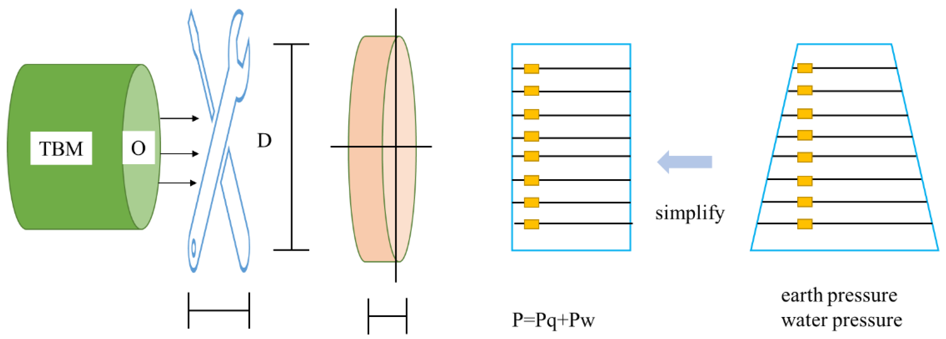
In the analysis and research of the force mechanism of the reinforced soil at the starting and arriving ends of the shield, the reinforced soil is often simplified as a circular thin plate. The stress on the reinforced soil at the start of the shield is similar to that at the end of the shield, and the reinforced soil at the end is affected by the lateral combined water and soil force [19]. The simplified mechanical model is shown in Figure 1.
According to the basic knowledge of the plate theory of elastic mechanics, it is assumed that the diameter of the end reinforcement soil is D. According to the basic knowledge of soil mechanics, the thin circular plate is subjected to hydrostatic pressure and lateral earth pressure, and the combined force of the two is a trapezoidal load. The trapezoidal load acting on a circular section is an asymmetric problem, and the mathematical model is quite complex. It is very difficult to obtain an accurate solution that satisfies all the basic equations and boundary conditions. In previous mechanical models, the trapezoidal load is simplified to a uniformly distributed load, and then the axial symmetry knowledge of elastic mechanics is used to obtain the longitudinal reinforcement range that meets the strength criteria, as shown in Figure 1.
(3) Elasticity Theory Model
Shield end reinforcement is an important part of shield starting and arriving technology. After the tunnel door is broken, the soil body at the end is exposed, the force balance of the stratum at the end is destroyed, the structure, load, and stress of the soil body at the end will change, and the collapse of the tunnel door will occur from time to time [
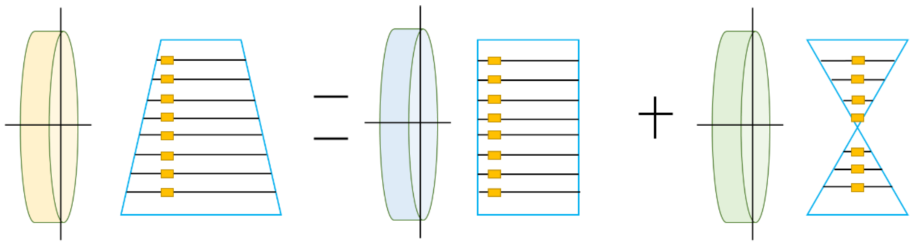
20]. Therefore, it is necessary to pay attention to the rationality of the reinforcement scheme for the soft soil layer at the end and the control of the reinforcement quality. It is very necessary to strengthen the front end of the excavation, as shown in Figure 2.
The result of the solution after the trapezoidal load is simplified to a uniformly distributed load is dangerous. Given this, the pros and cons of traditional research methods are summed up through analysis and research of traditional mechanical models, and the equivalent mechanical model is found within the range of elasticity that is allowed. According to Figure 2, the trapezoidal load is equivalent to the superposition of a uniformly distributed load and a triangular symmetric load, that is, the superposition of solving a symmetric problem.
The purpose of the stratum reinforcement at the end of the shield tunnel is to prevent the impact of vibration when the temporary enclosure structure is dismantled. Before the shield cutter head reaches the end of the face and establishes the earth pressure, it can stabilize the surrounding rock and prevent the loss of groundwater. The most common problems of soil reinforcement at the end in China are as follows:
(1) Improper design of the reinforcement range at the end, resulting in soil erosion at departure and arrival and engineering accidents such as water seepage, well flooding, and collapse. In the past, there were few studies on the scope of end reinforcement in China. The selection of the reinforcement range at the end was generally based on engineering experience, and the theoretical basis was weak [21]. The reinforcement range of the end reinforcement design is usually 3.0 m above and 3.0 m below the bottom plate, and the longitudinal reinforcement length is usually taken as 6~8 m.
(2) The selection of the reinforcement method of the end is unreasonable, the stratum adaptability is poor, the reinforcement effect of the end is not ideal, and the stratum of the end is collapsed when the tunnel door is broken. To ensure the safe departure and arrival of the shield, the above two problems must be solved, so that the stratum after reinforcement should have good uniformity and integrity, the stratum can stabilize itself after the hole is cut out, and has a good waterproof and anti-penetration function. In addition, after the end reinforcement is completed, a drilling core test should be carried out to check the reinforcement effect, and the unconfined compressive strength of the cored sample should reach 0.8 MPa. Drilling holes in the reinforcement area to check the seepage volume, the permeability coefficient should not be greater than 1.0 × 10⁻⁵ cm/s and the total seepage volume should not be greater than 10 L/min.
In this paper, when studying the stability of the soil at the beginning and end of the shield, to simplify the calculation, an ideal sliding failure model of the soil at the end is established. According to whether the soil has cohesion, it is divided into cohesive soil and sandy soil, and two different mechanical models are established, respectively. The stability of the soil at the beginning and end of the shield is analyzed; the range of soil instability and failure is deduced; and the reasonable reinforcement range of the soil at the end is determined.

2.3. Method of Reinforcement Design of Shield End

(1) Reinforcement design for soil stability
An ideal soil sliding failure model can be established for the reinforcement design of soil stability. At the same time, soil is divided into cohesive soil and sandy soil based on its different properties, and two different mechanical models are established accordingly. Through in-depth analysis of the stability of the model, the failure range of soil instability is deduced, and the scientific and reasonable reinforcement range is determined according to the results.
For cohesive soil, because of its viscous force, the slice method is usually used in the calculation of the mechanical model during design. The specific process is as follows: the sliding soil body is vertically divided into several strips, and these soil strips are regarded as rigid bodies, and the sliding moment and anti-sliding moment of different soil strips are obtained. According to the basic principle of static equilibrium, the sliding moment and anti-slip moment are obtained.
In sandy soil, there is no cohesion in the soil. According to statistical data, the failure process is mostly sudden, and the slip surface forms a linear slip surface from the top to the bottom. According to the principle of earth pressure and centrifugal experiment, it can be known that the failure surface of sandy soil is the vertical sliding surface. Based on this, a corresponding destructive force model can be established to carry out the necessary calculations.
(2) Determination of soil range
Scope of lateral reinforcement: To carry out tunnel construction, excavation must be carried out. After the excavation of the soil mass, the original stress balance is destroyed, which also has a certain impact on the surrounding soil mass. The stress is concentrated around the tunnel wall. If the maximum shear stress exceeds the shear strength at this time, the surrounding soil will be damaged to a certain extent and gradually spread to the surrounding, forming a plastic loose circle. The existence of the plastic loose circle causes the surrounding stress to be significantly reduced, and the maximum stress concentration is shifted to the boundary area between the plastic circle and the elastic circle. Therefore, to ensure the stability of the lateral soil, the necessary reinforcement work must be carried out in advance.
Scope of longitudinal reinforcement: If the construction soil is anhydrous, only the requirements of strength and stability need to be considered during reinforcement. For soil with water, in addition to meeting the above requirements, the body size and water-stop requirements of the shield machine must also be considered.
(1) After the tunnel is excavated, the shield cutter head has not yet carried out construction on the top excavation surface. There are two main purposes of reinforcement at this time: first, to meet the requirements of strength and stability, and to prevent the end soil from being pulled, sheared, and damaged under the action of water and soil pressure and leading to overall instability; second, to meet the requirements of water-stop, prevent the water in the stratum from infiltrating into the construction area, and the shield working well, thereby causing soil erosion and causing damage to the lower layer, resulting in subsidence or excessive subsidence of the surface.
(2) When the shield machine starts construction at the bottom of the end, the relevant longitudinal reinforcement range should be calculated first according to the strength and stability. At the same time, comparing it with the length of the main body of the shield machine, the following two situations will occur. First, the longitudinal reinforcement range is smaller than the length of the shield mainframe. When this happens, the longitudinal reinforcement range can be calculated according to the following formula, according to the requirements of geometric criteria and actual engineering experience: L2 = 2 × 3 × B, where L2 is the length of the shield machine and B is the width of the segment. Second, the longitudinal reinforcement range is greater than the length of the shield mainframe. When this happens, just take the calculated longitudinal reinforcement range.
(3) End reinforcement range technology
The two main theories based on the calculation of the longitudinal reinforcement length at the end are the elastic thin plate theory and the slip instability theory. The elastic sheet theory and slip instability theory satisfy the strength and stability requirements, respectively. There are two types of elastic thin plates: circular and rectangular. Among them, the circular thin plate model is widely used in the calculation of the end reinforcement range. Specifically, it can be divided into two processing methods: the uniform load calculation model and the uniform load plus inverse triangular symmetrical load. When the diameter of the tunnel is less than 10 m, the results of the two calculation methods have little difference.
(1) The strength check formula and the minimum longitudinal reinforcement length are calculated according to the uniform load model
max pull stress:
σ max = ± 3 ( 3 + μ ) p D 2 / 32 t σ t / k 1
Maximum shear stress:
τ max = p D / 4 t τ c / k 2
Minimum longitudinal reinforcement length:
t = max { 3 ( 3 + μ ) k 1 p D 2 / 32 σ t , k 2 p D / 4 τ c }
In the formula, D is the diameter of the tunnel door of the working well; t is the longitudinal reinforcement range; and p is the lateral water and soil pressure acting on the center of the tunnel door. For sandy soil, the water pressure and earth pressure are calculated separately. The soil pressure is considered the static earth pressure; μ is the Poisson’s ratio of the reinforced soil; σt is the ultimate tensile strength of the reinforced soil, which is generally 10% of the ultimate compressive strength, that is, σt = qu/10; τc. To strengthen the ultimate shear strength of soil, the value is selected according to experience, τc = qu/6; k1, k2 are safety factors, generally 1.5.
(2) Longitudinal reinforcement length as specified by the Japanese JET GROUT Association (JJGA)
h = ( K 0 β p D 2 / 4 σ t ) 1 / 2
In the formula, safety factor K0 is taken as 1.5 to 2.0, and the calculation coefficient β is taken as 1.2. Other symbols have the same meaning as before.
The ideal global slip theory in the clay stratum holds that the reinforced soil may slide as a whole in the tunnel along a certain sliding plane under the combined action of the ground overload p and the upper soil. The hole diameter is the arc surface of the radius.
(3) The longitudinal reinforcement length of the end obtained by the ideal global slip instability theory
Sliding moment:
M = p D 2 / 2 + i n γ i H i D 2 / 2 + γ t D 2 / 3
Anti-slip moment:
M d = c H D + c D 2 ( π / 2 θ ) + Δ c θ D 2
θ = ( K M M d ) / Δ c D 2
where M is the sliding moment; Md is the anti-sliding moment; Δc is the increased cohesion of the soil after improvement; K is the anti-sliding safety factor; θ is the angle between the reinforced soil and the sliding surface; γt is the tunnel range Inner soil weight.
(4) Lateral reinforcement technology
The lateral reinforcement range of end reinforcement is mainly to consider the disturbance range of the soil around the cave after the removal of the door and the enclosure structure. The theoretical basis is the limit equilibrium theory of soil disturbance. The lateral reinforcement range must be larger than the disturbance range (plastic circle) to ensure lateral stability.
The scope of reinforcement on the upper and lower sides of the tunnel:
H 1 = H 2 = k ( R D / 2 )
Reinforcement range on the left and right sides of the tunnel:
L = ( D / 2 + H 1 ) cos β D / 2
where k is the reinforcement safety factor.
Usually, soil layers include the following types: first, fill layer; second, silty soil layer; third, cohesive soil layer; fourth, silt layer, clay soil, etc. For this type of stratum, the reinforcement methods include the following two: cement-soil mixing piles and rotary jetting piles or freezing methods. When the nature of the soil layer is a round gravel layer, the key technology to be solved during reinforcement is the water-stopping effect of the reinforcement. Under normal circumstances, a high-reliability, plain silicon diaphragm wall is used to stop water. When the soil layer is mudstone, the usual method is to retain the soil with silicon piles outside the hole.

2.4. Research on the Strength of Soil Reinforcement at the End

The soil at the end of the shield when entering and exiting the hole generally needs to be reinforced, and the reinforced soil has a certain strength. Therefore, from this aspect, the reinforced soil will generally deform greatly before the strength failure occurs. In the end soil strength analysis, the reinforced end soil is generally assumed to be an elastic thin plate, but in practice, the thickness of the end soil is much larger, so this simplification is relatively safe. To prove the correctness of the simplification of the reinforced end soil, finite element analysis technology can be used to calculate the reinforced end soil, and the results can be compared with the actual situation. In addition, experimental methods can also be used to verify the simplified results.
According to the plate model theory stipulated by the JET GROUT Society (JJGA), when analyzing and studying the reinforced soil at the end of the shield, the soil at the end is generally assumed to be a thin cylindrical plate. In this model, the soil at the end is assumed to be an elastic circular plate supported by the surrounding elastic and subjected to the combined force of the longitudinal water and soil pressure of the tunnel. The maximum bending stress appears at the center of the circular plate, and the shear force at the support is the largest. According to the principle, the strength check formula can be obtained:
σ max = ± β P D 2 4 t 2 σ t k
where D is the diameter of the tunnel door; t is the reinforcement thickness of the longitudinal soil; P is the resultant force of the longitudinal water and soil pressure on the sealing door of the tunnel; μ is the Poisson’s ratio of the soil; σt is the ultimate tensile strength of the soil; left is the safety factor, which is generally taken as 1.5.
According to the thin circular plate theory, the required soil reinforcement thickness is:
t 1 3 k ( 3 + μ ) P D 2 32 σ t
According to the principle of elastic mechanics, the check formula for sheet shear force can also be obtained:
τ max = P D 4 t t c k
In the formula, τc is the critical shear strength of the soil at the reinforced end, usually τc = q/6; k is the safety factor, generally 1.5.
From Formula (13), it can be calculated that the soil reinforcement thickness that meets the shear resistance requirements of the soil is:
t 2 k P D 4 τ c
To make the reinforced soil meet the requirements of both the tensile strength and the shear strength of the soil, the thickness of the reinforced soil should meet the following formula:
t = max { t 1 , t 2 }
Because the soil at the end does not have a high modulus like steel or concrete, it tends to undergo large deformations before failure, and the bearing capacity is not controlled by the strength. Rear stability is particularly important for end reinforcement.
The ground load is the moment caused by the self-weight of the overlying soil and the moment generated by the soil within the slip plane inside the hole n, which can be calculated according to the following formula:
M = M 1 + M 2 + M 3

3. Experimental Results and Analysis

3.1. Numerical Simulation of Intelligent Reinforcement of Shield Tunnel End

The numerical calculation software used in this paper is PLAXIS 3D (PLAXIS 3D 2020). The model size used in the finite element analysis is the same as the corresponding test size, which is 1.1 m × 0.9 m × 1.2 m. The finite element software PLAXIS3D uses the function of material data groups to divide the functional attributes of each soil layer and structure into different categories for construction: soil and interface, geogrid, beam, plate, anchor rod, and embedded pile. When defining soil parameters, you need to enter the data group for soil and interface, select the constitutive model of soil, and fill in the corresponding data to get the soil model.
According to the construction sequence and stratum loss unloading in the actual test, the test process of simulating shield tunnel end reinforcement is divided into nine steps, and the construction stage is defined in the PLAXIS 3D distributed construction interface. The specific steps are as follows:
(1) Initial phase: the stress field of the whole model is in equilibrium by generating initial stress; (2) Tunnel placement: freeze the soil above the tunnel’s top buried depth and simulate the excavation process before placing the tunnel; Then activate the plate element of the tunnel model and activate the corresponding forward interface, which simulates the process of placing the tunnel model; (3) Generate pile group foundation: activate the frozen soil at the upper part, activate the pile group foundation and positive interface, and simulate the construction of pile groups. To prevent the activation of the pile foundation structure from changing the original stress state of the soil and causing the displacement of the soil, the displacement of this step is reset to zero; (4) Simulate the formation loss: activate the surface shrinkage of the model tunnel slab unit and set the value of the surface shrinkage to simulate the formation loss process of tunnel excavation.

3.2. Indoor Triaxial Test in Seaside Environment

The test adopts an automatic triaxial instrument; the user only needs to set the test parameters, and the software will perform the test in h motion. The shear rate of 0.5% for sandy soil and 0.3% for cohesive soil. Figure 3 and Figure 4 show the relationship between the axial strain and the deviatoric stress σ1–σ3 in the soil sample failure test when Σ3 = 100 KPa.
During the experiment, it was found that in the same soil sample, due to the differences in the preparation of the sample, it will have a certain impact on the experimental results, and this effect is particularly prominent in sandy soil. Therefore, when preparing the sample, attention should be paid to fully mix the soil and water and maintaining it for a certain period of time to make the water uniform; secondly, in the process of sample compaction, under the condition that the density of the sample is controlled as much as possible, a small amount of time should be used. Compaction to reduce the impact of uneven compaction.

3.3. PFC Numerical Biaxial Test

In the biaxial test, the failure of the sample is generally caused by the formation of a shear zone. Due to the discontinuity of geotechnical materials, it is difficult to simulate the failure process and failure phenomena in numerical simulation. PFC (Particle Flow Code) software uses particles It is the basic unit, which is the same as the basic unit of soil in shape and structure, and can visually display the failure mechanism inside the soil in the biaxial test. And because of its discrete characteristics, it can effectively simulate the discontinuity of geotechnical materials and reflect the failure process of soil from a microscopic view.
From Figure 5, it can be seen that the sandy soil sample has obvious shear dilatation during the shear failure process. The reason for this phenomenon is that the close arrangement of sand particles is destroyed during the shearing process. When the axial strain reaches the stress peak, it appears in the sand sample model at 3% to 6%. In the PFC model, linear contact bonding is used. In this contact model, a mode that allows sliding between particles is adopted, and the maximum static friction force between particles in the model is generally It is greater than the sliding friction force, which is in line with the mechanical properties of sand.

3.4. Macroscopic Reflection of Particle Friction Coefficient

In the PFC2D biaxial numerical simulation, the particle friction coefficients Eric = 0.1, Eric = 0.3, Eric = 0.5, Eric = 0.7, and Eric = 0.9 were used to analyze the effect of particle friction coefficient on the macroscopic characteristics of soil, as shown in Figure 6.
When the confining pressure is small, the particle friction coefficient is related to the peak strength. The influence of strength is still positively correlated, but the correlation decreases. Analysis of the relationship curve shows that the friction coefficient has little effect on the peak strength before 0.3, and when the particle friction coefficient is greater than 0.3, its influence on the peak strength is significantly enhanced.
To obtain the specific value of soil deformation and displacement, 18 characteristic particles are selected by the fish language definition program, as shown in Figure 7, where the displacements in the x and y directions of the No. 1–5 characteristic points change with the number of operation steps. It can be seen that in the early stage of soil failure, the soil particles generally have vertical displacement and small lateral displacement. This is because there is no sliding surface in the soil in the early stage, but the settlement is caused by the loosening of the soil. In model iteration operation I.5, during the period from 10,000 steps to 35,000 steps, the displacement of the particles is very small. The author believes that this is due to the temporary stability of the soil caused by the arching effect of the sand. The displacement of particles after destabilization is larger. Similar to the staged instability predicted from the particle velocity, the vertical displacement curve of soil particles also shows obvious stages.

4. Conclusions

The instability and damage of the soil at the end of the shield are important safety hazards in the construction of shield tunnels. In the loose and weak strata, the risk of such instability and damage is higher, and the loss is also greater. In this paper, the instability and failure of the end soil in the loose and weak stratum are studied. The physical and mechanical properties of the soft and loose sand and clay are analyzed through the indoor triaxial test. The indoor model test combined with the numerical model test of the PFC end is designed to study the instability failure mechanism of the upper body of the end in the soft and loose stratum, analyze its influencing factors, and calculate the reinforcement stability factor. The main conclusions are as follows: (1) The indoor triaxial test shows that the flexible wall not only makes the boundary conditions closer to the actual test but also saves the traditional wall servo and calculation time. (2) With the help of the PFC biaxial test, the influence of model parameters on the macroscopic properties of the simulated material was analyzed. In the sand model, when the horizontal pressure was small (less than 150 kPa), the failure peak was positively correlated with the friction coefficient of the particles, and when the coefficient is larger (greater than 0.3), its influence on the strength is significantly enhanced. The internal friction angle and cohesion force of the model have an approximately linear relationship with the friction coefficient of the particles and the bond strength, respectively, which is the most important factor in the PFC modeling.

Author Contributions

H.Z. designed the experiments. H.Z. and T.L. performed experiments and data analysis. H.Z., T.L. and J.H. performed data analysis and wrote the manuscript, with contributions from all authors. All authors have read and agreed to the published version of the manuscript.

Funding

This work was supported by the characteristic innovation (Natural Science) projects of scientific research platforms and scientific research projects of Guangdong Universities in 2021 (Grant No. 2021KTSCX139).

Data Availability Statement

The figures used to support the findings of this study are included in the article.

Acknowledgments

The authors would like to show sincere thanks to those techniques that have contributed to this research. The authors extend their appreciation to the characteristic innovation (Natural Science) projects of scientific research platforms and scientific research projects in Guangdong Universities in 2021 for funding this research work through project number (2021KTSCX139).

Conflicts of Interest

The authors declare no conflict of interest.

References

  1. Li, Z.; Chen, Z.; Wang, L. Numerical simulation and analysis of the pile underpinning technology used in shield tunnel crossings on bridge pile foundations. Undergr. Space 2021, 6, 396–408. [Google Scholar] [CrossRef]
  2. Han, B.; Yuan, D.; Wang, T. Numerical Investigation of Slurry Fracturing during Shield Tunneling under a Reservoir. Appl. Sci. 2022, 12, 7929. [Google Scholar] [CrossRef]
  3. Zhao, B.; Wang, X.; Zhang, C. Structural Integrity Assessment of Shield Tunnel Crossing of a Railway Bridge using Orthogonal Experimental Design. Eng. Fail. Anal. 2020, 114, 104594. [Google Scholar] [CrossRef]
  4. Zhang, X.D.; Wang, J.C.; Chen, Q.J. Analytical Method for Segmental Tunnel Linings Reinforced by Secondary Lining Considering Interfacial Slippage and Detachment. Int. J. Geomech. 2021, 21, 04021084. [Google Scholar] [CrossRef]
  5. Ma, S.J.; Li, M.Y.; Guo, Y.C. Field test and research on shield cutting pile penetrating cement soil single pile composite foundation. Geomech. Eng. 2020, 23, 513–521. [Google Scholar]
  6. Lu, Y.; Song, Y.; Wang, Y. Three-Dimensional Nonlinear Seismic Response of Shield Tunnel Spatial End Structure. Adv. Civ. Eng. 2021, 2021, 8441325. [Google Scholar] [CrossRef]
  7. Li, Z.; Lv, J.; Xie, X. Mechanical characteristics of structures and ground deformation caused by shield tunneling under-passing highways in complex geological conditions based on the MJS method. Appl. Sci. 2021, 11, 9323. [Google Scholar] [CrossRef]
  8. Liang, Y.; Chen, X.; Yang, J. Analysis of ground collapse caused by shield tunnelling and the evaluation of the reinforcement effect on a sand stratum. Eng. Fail. Anal. 2020, 115, 104616. [Google Scholar] [CrossRef]
  9. Han, W.; Wang, X.; Han, L. Study on the optimum grouting materials and their performance in the TBM tunnel collapse reinforcement project. IOP Conf. Ser. Earth Environ. Sci. 2020, 570, 052065. [Google Scholar]
  10. Liu, H.; Dong, B.; Zhu, J. Numerical Simulation and Control Measures of Seepage Field and Displacement Field of a Shielded River Crossing Tunnel. Soil Eng. Found. 2022, 36, 65. [Google Scholar]
  11. Chen, J.; Min, F.; Wang, S. Large Diameter Shield Initiation and Arrival Technique; Springer Nature: Singapore, 2022; Volume 27, pp. 7101–7108. [Google Scholar]
  12. Qiu, H.; Wang, Z.; Ayasrah, M. Numerical Study on the Reinforcement Measures of Tunneling on Adjacent Piles. Symmetry 2022, 14, 2869–2885. [Google Scholar] [CrossRef]
  13. Wang, F.; Shao, J.; Li, W. Numerical simulation study on lining damage of shield tunnel under train load. Sustainability 2022, 14, 14018. [Google Scholar] [CrossRef]
  14. Sun, T.; Song, K.; Huang, T. A Modified Elastic Plate Model for the Thickness of Reinforced Soil of Shield Tunnel End. IOP Conf. Ser. Earth Environ. Sci. 2020, 570, 022010. [Google Scholar] [CrossRef]
  15. She, C.; Zhang, B.; Zheng, J. Theoretical Analysis of Bearing Capacity for Shield Tunnel Reinforcement Structure. IOP Conf. Ser. Earth Environ. Sci. 2020, 455, 012171. [Google Scholar] [CrossRef]
  16. Jiang, L.; Hao, S. Resilience Evaluation of the Existing Shield Tunnel Lining Induced by the Symmetrical Excavation of Adjacent Foundation Pit Based on Numerical Simulations. Symmetry 2022, 14, 229. [Google Scholar] [CrossRef]
  17. Gong, C.; Wang, Y.; Ding, W.; Lei, M.; Shi, C. Waterproof performance of sealing gasket in shield tunnel: A review. Appl. Sci. 2022, 12, 4556. [Google Scholar] [CrossRef]
  18. Li, C.; Wang, Z.; Liu, Q. Numerical Simulation of Mudstone Shield Tunnel Excavation with ABAQUS Seepage–Stress Coupling: A Case Study. Sustainability 2023, 15, 667. [Google Scholar] [CrossRef]
  19. Hu, Y.; Lei, H.; Zheng, G. Assessing the deformation response of double-track overlapped tunnels using numerical simulation and field monitoring. J. Rock Mech. Geotech. Eng. 2022, 14, 436–447. [Google Scholar] [CrossRef]
  20. Zheng, F.; Jiang, Y.; Wang, N. Investigation on the Influence of Active Underpinning Process on Bridge Substructures during Shield Tunnelling: Numerical Simulation and Field Monitoring. Buildings 2023, 13, 241. [Google Scholar] [CrossRef]
  21. Lu, S.; Zhao, D.; Dai, J. Shaking Table Test and Numerical Simulation Study on Tunnel-Soil-Bridge Pile Structure Interaction System. Sustainability 2022, 15, 286. [Google Scholar] [CrossRef]
Figure 1. Simplified mechanical model.
Electronics 12 01361 g001
Figure 2. Equivalent force model of end-reinforced soil.
Electronics 12 01361 g002
Figure 3. Deviatoric stress curves of sandy soil under different confining pressures.
Electronics 12 01361 g003
Figure 4. Clay deviatoric stress curves under different confining pressures.
Electronics 12 01361 g004
Figure 5. PFC simulation deviatoric stress curves of different sandy soils.
Electronics 12 01361 g005
Figure 6. Relationship between particle friction coefficient and peak strength.
Electronics 12 01361 g006
Figure 7. Part of the characteristic point y: direction displacement curve.
Electronics 12 01361 g007
Disclaimer/Publisher’s Note: The statements, opinions and data contained in all publications are solely those of the individual author(s) and contributor(s) and not of MDPI and/or the editor(s). MDPI and/or the editor(s) disclaim responsibility for any injury to people or property resulting from any ideas, methods, instructions or products referred to in the content.

