1. Introduction
In order to enhance the energy conservation by the optimized data delivery from far-flung areas whenever the external intervention seems to be involved, is impossible, as the self-organized, ubiquitous wireless sensor networks are actually experiencing the greatest challenges. As sensor networks expand and quickly advance in their capacity to measure real-time information in an accurate and reliable manner, a new research problem about how to gather and interpret this generated information arises. Most of the smart monitoring applications where human intervention is really difficult are mostly handled by sensor network and the IoT (Internet of Things) devices [
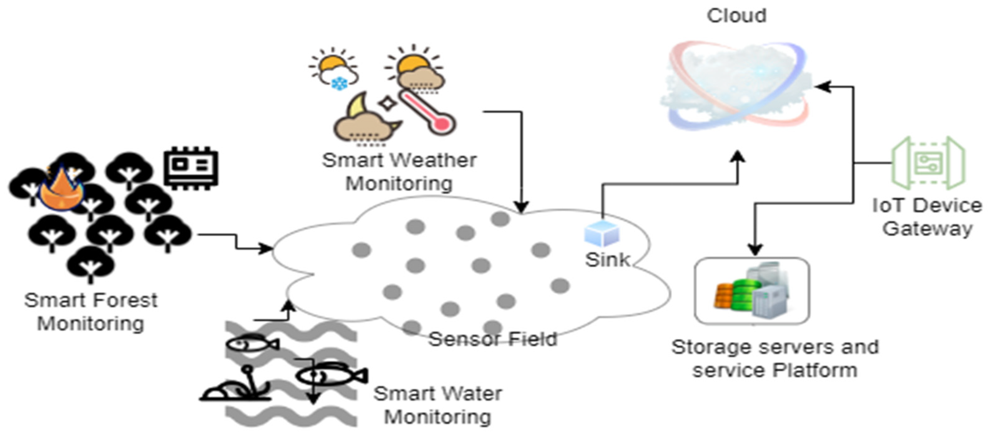
1]. A smart monitoring network model utilizing sensor networking and the IoT is shown in
Figure 1. The technologies, such as the IoT and wireless sensor networks on the ground level make the monitoring process much more effective. The sensor nodes with on-board batteries operate a trigger to detect the surroundings and disseminate the essential base station collecting data. Since direct data transmission to the base station is not possible because of the limited transmission range, the multi hop communication has emerged. Multi path routing architectures enable building up propagation routes between each sensor node, as well as the base station, since this failure rate in a single path from the remote nodes to the base station would be high, making data gathering reliable against communication failures [
2]. Therefore, the data obtained from a sensor node can be conveniently sent to the base station as long as any of the propagation pathways is active. The interference also grows as the number of possible routes increases. Therefore, the optimized multiple-path routing delivers data to a bunch of nodes, instead of to all nodes, in order to effectively handle the congestion, enhancing the energy conservation and network durability.
One of the difficulties that could lead to a route breakdown and the termination of end-to-end communication is frequent node movement. Whenever a node moves, the network will be completely disrupted, using up more of the available energy. A network performs less well, in terms of quality-of-service metrics, and consumes an excessive amount of energy in the event of excess traffic. A link failure increases the network’s load and consumes energy until the route discovery occurs. All of these will result in a reduction in the network performance by boosting the load, decreasing the throughput, and subsequently decreasing the packet delivery ratio. Therefore, it is intended to develop a mechanism that utilizes less energy and ultimately performs better. Extensive research was undertaken to determine the most efficient method to use energy at mobile nodes, especially in order to prolong the network’s durability [
3].
The major issues considered for (mobile wireless sensor networks) MWSNs involves the post deployment knowledge of the sensor locations. Again, extra memory space is required to manage the control overhead. The routing and mobility management schemes have received a great deal of attention and are frequently used in networks for objectives including the enhanced lifespan, congestion control, fault tolerance, and real-time information dissemination. Sajwan et al. [
4], in order to aid in the establishment of networks, proposed an analysis of several multipath routing protocols and their problems. Furthermore, the given multipath scheme is energy efficient, which utilizes intra cluster communication.
Regardless of the advantages, the sink mobility poses the problem of the sink localization and precludes the regular sink node location change advertisements. To reap the benefits of the energy efficiency that the mobile sinks offer, the control overhead associated with this operation should be minimized as much as possible. An efficient sink routing strategy should be employed in order to prevent a dramatic increase in the propagation delay of the sensor data [
5]. In specifically considering the time sensitive WSN applications, the relevance of the data pertaining to the sensors’ impacts is its validity. For example, in a habitat monitoring system, robots are considered as mobile sinks to retrieve data from sensors deployed around a dense field. Other applications include the monitoring of traffic, the environment (such as pollution or the weather), and smart homes and healthcare facilities.
This paper primarily focuses on the implementation of mobile sinks for monitoring applications in a target region with proper advertisement, along with the improvement in the network’s lifespan and managing network latency and control overhead. The selection of the ring depends on the one-hop distance criteria, based on which algorithm is set. The rest of the paper is organized as
Section 2 with the basic background and the related works, followed by the problem modelling and formulation, as discussed in
Section 3. The modified ring routing for the MWSN is discussed in
Section 4. Further, we simulated and analyzed our proposed ring model with different state of the art models, as cited in
Section 5 followed by the conclusion in
Section 6 and the references.
2. Basic Background and Motivation
In this section, the motivation for the implemented ring routing protocol and its use in smart monitoring applications is discussed. Goyal et al. [
6] analyzed the different routing protocols with the sink mobility providing a better load balancing and energy efficiency. Additional effort is required to overcome the overheads, which are added costs, due to the frequent position broadcasting. Different papers discuss the sink mobility and various protocols, most of which are suitable to provide scalability and energy efficiency. The sink in the mobility-based WSNs is carried by intelligent robots or vehicles and may roam freely across the sensor field. The sensor nodes of a wireless sensor network (WSN) are battery-powered devices that gather environmental data and transmit them to a sink for further processing, using energy from their batteries in the process. In some circumstances, it could be challenging to replace or recharge the batteries. These issues have paved the pathway for the development of novel sensor node energy-efficiency strategies. The energy hole problem, also known as the hot-spot problem, is a well-known scenario in which the sensor nodes exhibit many-to-one communications with the sink, causing the rapid energy depletion of the sensor nodes close to the sink [
7]. The balancing of the sensor nodes’ energy usage can be facilitated by the sink’s mobility.
Different strategies have been established to address the WSN constraints. One such constraint on the energy use is resolved by the dynamic routing in the hierarchical WSN. Zhou et al. [
8] have published a series of papers that investigate the cluster-based analysis from the different hierarchical approaches. They have, however, addressed an effective manner to choose a cluster head (CH) before even considering energy efficiency. The various techniques of clustering were evaluated for several metrics, as part of the clustering analysis carried out in [
9]. As per Caesar et al. [
10], the nodes are arranged in a virtual ring, in the order of their IDs, and each node retains a limited number of routing connections to its ring neighbors. However, a local neighborhood group, rather than a business network, could find it useful. However, as discussed in [
11,
12], the network’s nodes are built to broadcast information to the other nodes about the current traffic environment [
13], via short beacon messages that contain speed, direction, locations, and other pertinent safety information [
14]. The assessment of several energy-efficient and multicast routing schemes was implemented by the authors in [
15] in a number of protocols, whereas this increased the control overhead.
The clustering protocol that is adaptively immune energy efficient in the mobile sink (MSIEEP) is a controlled sink mobility-based system built by Javid et al. [
16]. The considerations taken for the CH selection are the quantity of living nodes and the energy on the nodes. The adaptive immune algorithm (AIA), which is also used to estimate the optimal number of CHs [
17], regulates the mobile sink in this strategy. The mobile sink uses the finest sojourn route patterns. At first, the network is split into different areas of equal-size. Then, the network’s territory is separated into three distinct configurations. The mobile sink based routing (MSRP) protocol in [
18] employs a mobile sink to gather data from the CHs, it broadcasts a time division multiple access (TDMA) schedule to all neighboring CHs, and keeps track of the network’s remaining energy. However, it results in a significant increase in the data delivery delay in the areas of the network where certain events happen often. Similar to [
19], the authors suggested a rendezvous zone as a vertical strip or line of the sensor networks that meets the query message along both directions, until it reaches the desired inline sensor network, at which point it is routed straight to the sink node. Again, the data gathering and dissemination was placed in the inline nodes. The area-based line structures are simple to create, are accessible to source and the sink nodes can reduce the hotspot issues, although flooding through them increases the energy usage. The goal is accomplished using the mobile wireless sensor network’s design [
20].
The directional routing scheme discussed in [
21] involves the strategies to develop the path selection criteria between the source and destination. Similarly, various energy efficient schemes for the dynamic wireless sensor network as provided in [
22] and gives an idea on the different strategies to develop such a network. Rendezvous routing discussed by Xing et al. [
23], has recently been the focus of numerous studies aimed at reducing the utilized energy and prolonging the lifespan of the sensor networks. Based on the virtual ring formation discussed in [
24], ring routing is a rendezvous routing mechanism. While using geographic routing to forward the packets in the route of the base station, the sink makes its position accessible to the ring. As a result, the ring nodes always preserve the sink’s most recent position. By using a similar technique, the source nodes ask the ring for the most recent sink location information. While preserving the enclosed and encapsulated information from the network center features, each ring node freely chooses new ring nodes among its neighbors when its batteries are almost empty. Even if the ring structure can be accessed easily, the proposed mitigation approach results in a low overhead, it becomes challenging to conserve energy and regulate the overhead in large or sparse networks. Thus, the multipath-based multicast routing concept is introduced in [
25]. In our work, we concentrated on the idea of the construction of ring routing with a multicast mechanism that aids in the resolution of these issues.
Most of the state of art techniques ignore the delay and the related packet loss brought on by the sink mobility, due to the frequent sink position advertisement, which increases the energy consumption and decreases the network’s lifespan. As cited in [
26] the authors have proposed an energy and delay efficient data acquisition technique by selecting optimal visiting points. However, the selection of the grid points is time consuming. This motivated us to develop the proposed work for resolving the objective of optimizing the determination of the nodes for the sink advertisement, thereby optimizing the energy utilization by managing the control overhead in a mobile sink. Thus, the lesser sink position advertisement, due to the sink mobility throughout the network provides faster data delivery. The major contributions of our paper are as follows.
The network deployment of the hierarchical-based heterogeneous wireless network with the mobile sink;
The cluster head selection, based on the residual energy assuming at least one per group with a higher energy density than the normal node;
The selection of the ring node by obtaining the one-hop neighbor enclosing the sink node which contains the maximum residual energy to store and forward the sink node link advertisement to the cluster head;
The modified ring implementation, based on the multicast and multipath approach with the performance evaluation, such as the control overhead, energy utility, throughput and delay metrics.
3. Proposed Network Model and the Problem Formulation
This section describes the assumptions for modelling the network followed by the cluster head selection. Subsequently, the inter and intra cluster communication is described. The objective of the proposed protocol depends on the selection of the CH and the reconfiguration of the network fused with the mobile sink. The mobile sink node subsequently gathers the data from each cluster head node in the wireless sensor network’s intelligent monitoring system after the sensor monitoring node sends the data to each cluster head node. Following the data dissemination, the analysis is carried out at the remote center, via the cloud and the IoT device gateway, to provide the proper service. The majority of the routing algorithms emphasize enhancing the sensor network’s QoS (quality of service) performance at the expense of the processing time. As a result, a considerable quantity of energy would be used during the prolonged processing period required to select the ideal approach. Batteries would be depleting as the routing requests grew and took longer to process, owing to the complexity of the routing algorithm, which would become actually responsible for powering the sensors. Due to this, the network’s performance is hampered, in terms of the data throughput and the communication time between the end nodes; consequently, alternate route is considered. In order to prevent dead nodes, which ultimately result in hotspot issues, especially during the data communication time, the routes should be chosen to run across the nodes with the cluster heads that appear to have a greater energy. To combat this, the mobile sinks and the regular position advertisements are used. The ring routing management is organized as the intermediary nodes that are simple for the sink and the nodes to contact, in order to pass on the location information. The network actually runs quite quickly and efficiently. Despite the ring routing protocol’s emphasis on routing in [
27], the energy hole problem develops during the multi-hop communication when the nodes closer to the sink consume more energy because of heavy relay traffic. Ring routing is an effective protocol, because the ring structure is simple to access and the hotspot mitigation technique has little overhead. The fast data transfer is made possible by the simple and quick acquisition of the additional sink location information from the ring [
28]. However, the cost of the first ring construction is expected to be significant for larger or sparse networks.
The proposed protocol is based on the following assumptions:
The sensor network is a heterogeneous model [
29] with a different energy distribution for the sensor nodes and sinks;
The placements of the sensor nodes themselves are known. Based on the deployment region, the localization may use a local or global geographic coordinate system;
The initial position of the sink node is at the center of the network. However, when the target region is far away from the sink node, it becomes mobile with the controlled mobility model and the greedy geographic routing;
The ring advertisement nodes are the one-hop or two-hop neighbour of the sink node. The frequent sink advertisement is conveyed to the cluster heads using the multihop fashion, assuming the cluster heads are available, with at least two in each quadrant;
The structure always encloses the sink node, allowing the ordinary nodes and the sink to access the ring, and vice versa. All sensor nodes must initially have a consistent understanding of the coordinates of a sink node. Prior to the deployment, the sensors’ memory can be filled with the sink node, which need not be precise.
The heterogeneous wireless sensor network is constructed with a different energy distribution for the remote nodes, the cluster head or the advanced node and the sink node [
30]. Based on the above-mentioned assumptions, the initial position of the mobile sink node is set at the middle of the sensor field.
The mathematical model for the formulation of the modified ring network is discussed in the subsequent sections that includes four phases of operations, as the deployment and the cluster formation, followed by the cluster head selection with the intra and inter cluster communication. The symbols and notations are mentioned in
Table 1.
3.1. Deployment and Cluster Formation
The deployment of the entire heterogeneous network is based on the placement of the different nodes with a different energy distribution for the remote, advanced and sink nodes [
31]. However, the sink node is associated with the mobilizer to enable the movement when required. Based on the above-mentioned assumptions, the initial position of the mobile sink node is set at the middle of the sensor field. The cluster head is selected from the set of advanced nodes only.
The entire sensor field is represented as
with the N number of nodes and the E number of links that is further divided into the number of sectors, and the CHs decide how many sectors there should be. Depending on its geographic information, each node joins a single cluster. The angle of each sector is given as Equation (1):
where
NCHs represents the CH count. Then, the node taking part in the cluster is represented using Equation (2):
where
x denotes the position of the sensor in the coordinate axis x, and
y denotes the position of the sensor in the coordinate axis
y with the node positioning as (
x,
y).
3.2. Cluster Head Selection
In the cluster head
(CH) selection, the residual energy of the nodes plays a significant role [
32]. The Euclidean distance parameter also provides a
CH selection criterion between the
CH and the sink. The data transmission to the sink is handled by the
CHs, that use a significant amount of energy in the process. As a result, it is important to choose the nodes that are closest to the sink. The weight of the sensors is determined using three alternative ways, and the simulation discusses the results. The weight of sensors
is represented by Equations (3)–(5).
where
represents the residual energy of the current node and
is the distance between the current node and the sink. The node nearest to the sink will initially notify its weight to other nodes in the cluster and declare itself to be a potential
CH. The nodes that broadcast their own weight and become new
CH candidates are those with a greater weight. The last
CH in each cluster will be chosen from the node with the maximum weight.
3.3. Intra Cluster Communication
The lifespan of the network is typically shortened by long-distance transmission, which uses a lot of energy. Long-distance communication should therefore be prohibited during intra cluster communication. Our proposed structure enables the member nodes to choose the best relay node or to send data directly by calculating the energy consumption cost of the various routing paths. Transmission uses around 1000 times as much energy as the calculation, as mentioned by Lambrou et al. [
33]. Hence, it is desirable to select a better routing path using the calculations. The energy consumption in the routing path using direct communication
can be calculated as
where
represents the communication distance between the corresponding
CH and the node with the distance threshold
. If the source node and its CH are far away from each other, a relay node
j will be chosen to forward the data package. The energy, from the direct path, depends on the energy from the transmitter electronics and receiver electronics
for
l bits with
that are the free space path loss factor and
the multipath loss factor. The total energy consumed during the entire routing is given in Equation (7), as follows:
where
is the transmission energy consumed,
is the reception energy consumed for
l bits of information over the distance.
The nodes compare
and
and select the smallest one as the routing path. The intra cluster communication can be determined using
3.4. Inter Cluster Communication and the Mobile Sink
The data processing and the communication distribution between the CH and the sink node is included in the intra cluster communication [
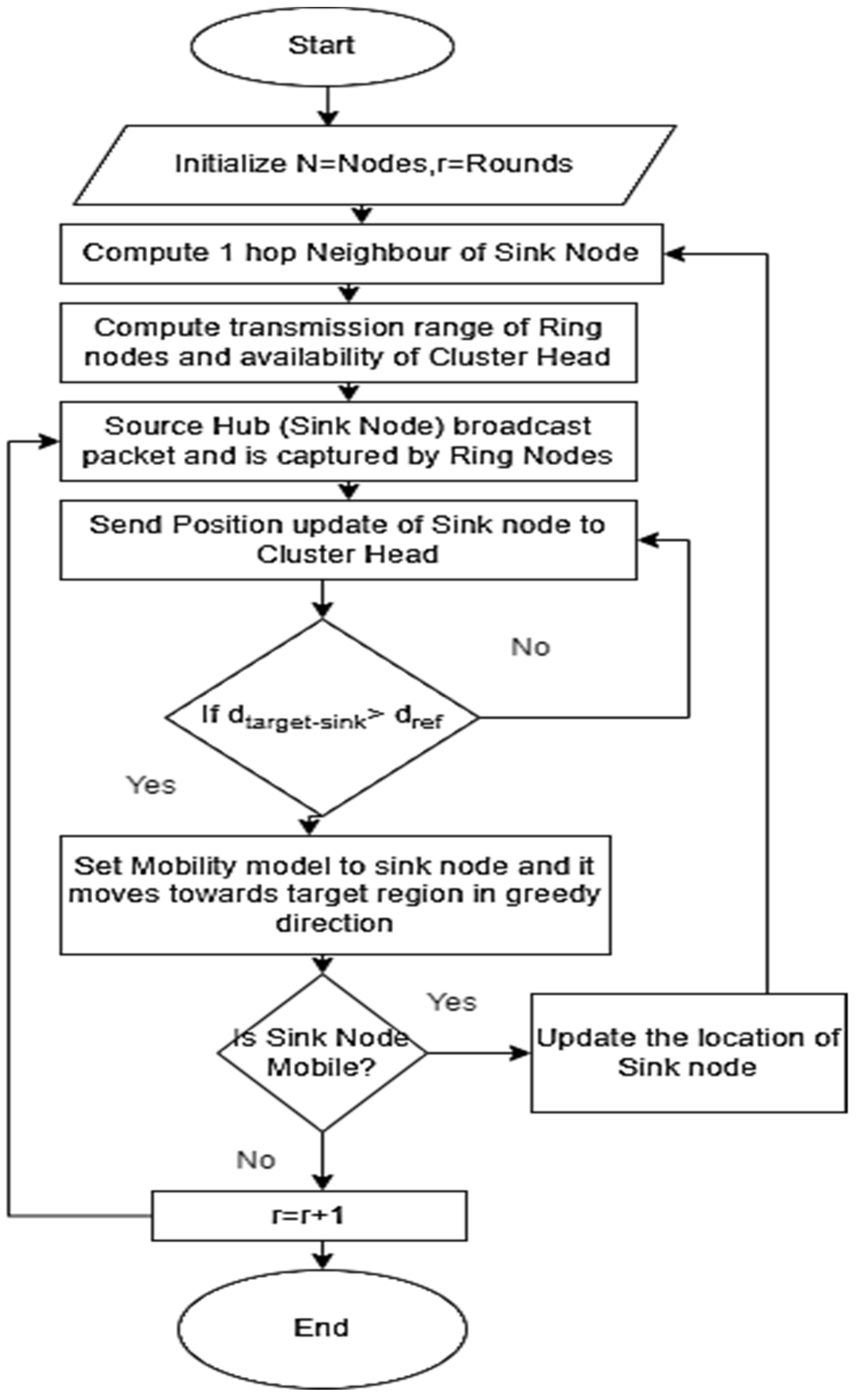
33]. As we take into account a mobile sink in this work, the CH must be updated with the sink node position.
Figure 2 indicates the process flowchart of initiating the ring node and broadcasting of the frequent sink node position advertisement throughout the network. The criteria for the mobility of the sink and the implementation of the ring routing protocol is discussed in the next section.
4. Modified Ring Routing for the Energy Efficient Mobile Sensor Network
In this Section, a mobile sink in the wireless sensor networks is considered. The proposed modified ring routing protocol, a cutting-edge hierarchical protocol, based on multicasting with a multipath problem is presented in this work. The protocol is built on three separate sensor node roles: ring node, cluster node, and distant sensor node. The details of the node implementation are shown in
Figure 3. A closed loop with a single-node width is created by the ring nodes. The ring routing’s essential features are (i) the position of the sink advertisement to the ring, (ii) the periodic request of the CH nodes for the sink position information from the ring, and (iii) the dissemination of the data to the remote nodes via the cluster nodes, that are considered as intermediary agents connecting the sink to the network.
4.1. Ring Construction
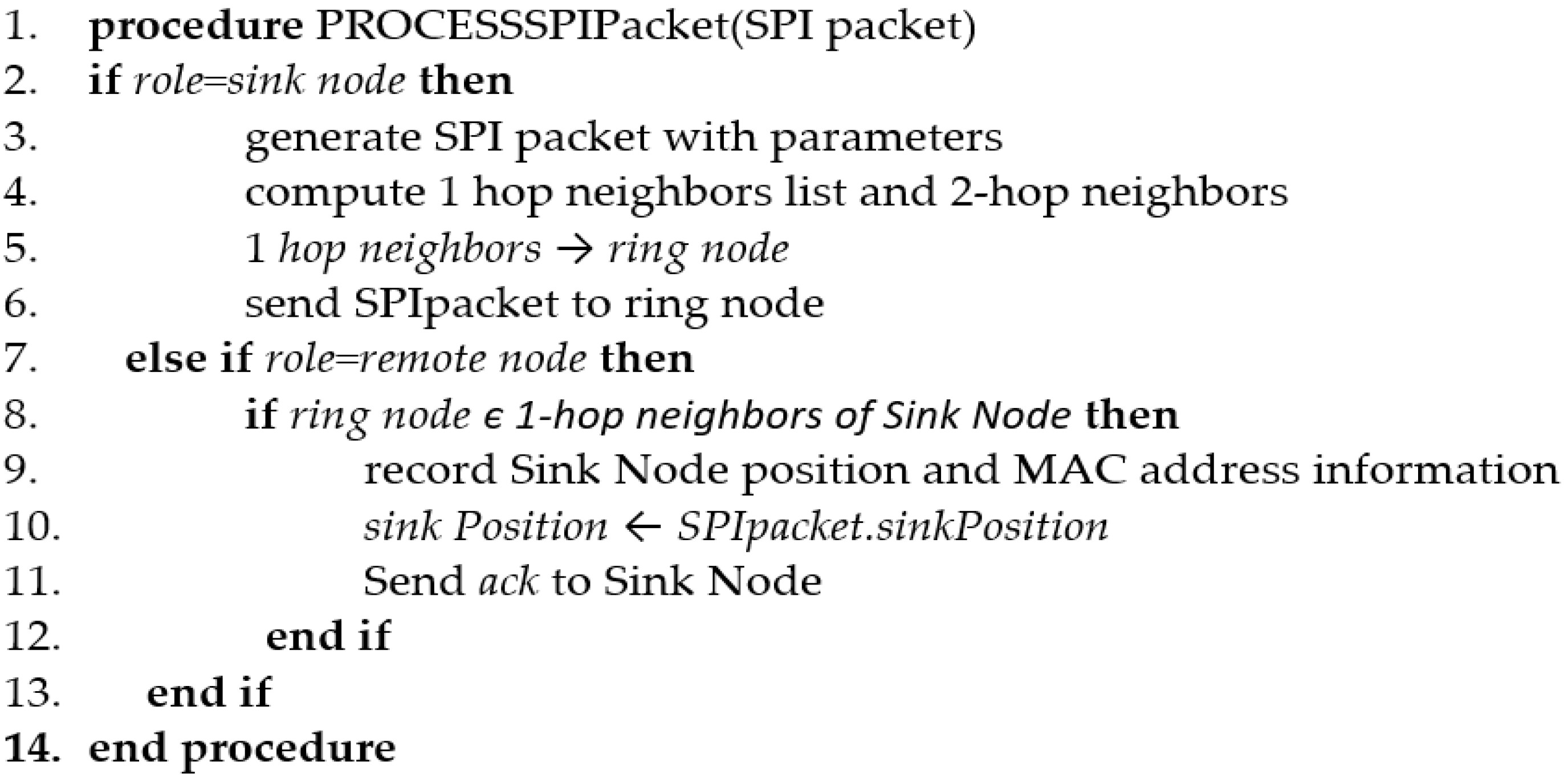
The closed, one-node wide strip of nodes, known as the ring node, is used to construct the ring. As long as a ring provides a closed loop, its shape is imperfect. It is chosen simply because it is one-hop to two-hops away from the sink node and can preserve the sink position information. A centralized decision entity is not necessary for the simple and energy-efficient initial ring creation method. A beacon message sent by the sink node to its one-hop neighbors, is further forwarded to its next hop. The one-hop neighbors are logically connected in a ring fashion. The frame format for the beacon message or the SPI (sink position information) packet in the ring node retains the sink advertisement, as given in
Figure 4.
The pseudo code of the procedure to process the SPI packets is provided in
Figure 5, as follows:
Since the ring nodes’ communication ranges are not exactly impressive, the localization errors are anticipated to be below 15 m in areas where construction is guaranteed to occur. Ring routing, however, is tolerant to localization errors up to a 30 m mean error profile.
4.2. Sink Mobility and the Sink Position Advertisement
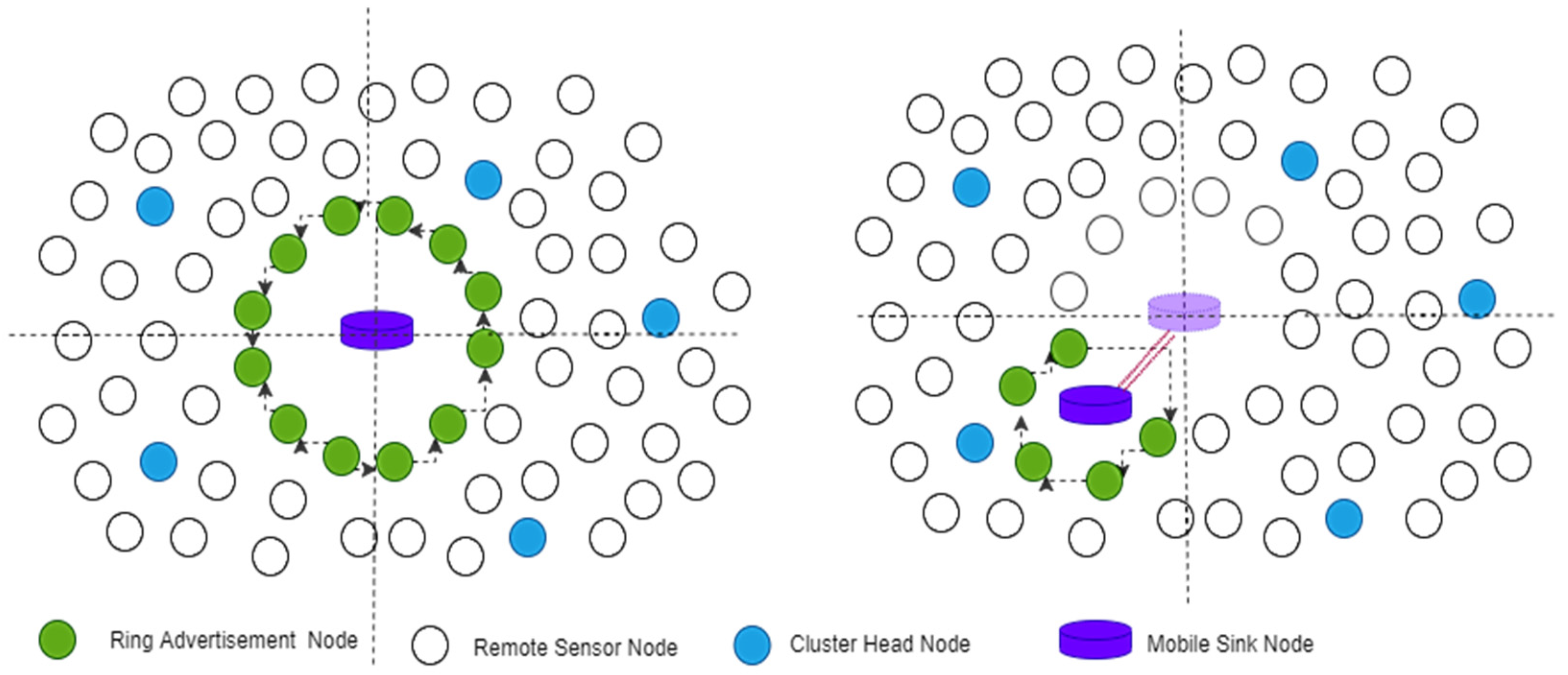
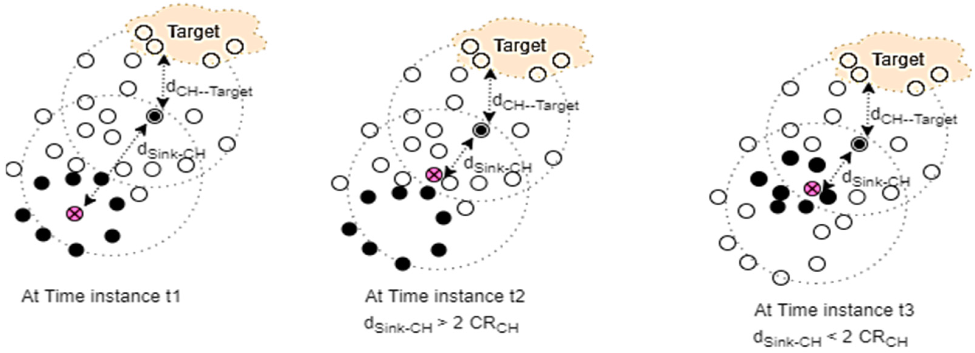
The sink mobility is based on the distance of the target from the sink node. Thus, the sink moves in a greedy fashion in the direction of the target using a controlled mobility model. The process of movement occurs in the following steps and is shown in
Figure 5:
Step 1: The sink broadcasts the beacon message which is updated in the ring node with a timestamp.
Step 2: The Ring node then forwards the sink advertisement to the CHs and receives the acknowledgement from the CHs with the information, such as the number of nodes attached to the CH, the distance of the CH from the sink, the distance of the CH from the target and the timestamp for receiving the information.
Step 3: Once the sink node receives this message from the ring node, it then computes the distance with respect to the target. where is the communication range of the CH. If the condition , then the sink becomes mobile with a constant velocity in the direction of the target.
Step 4: Then the Sink node position is modified in the ring node using the sink node’s initial position and time movement. Therefore, the message broadcasted by a network is significantly decreased while sustaining the overhead as the mobile sink merely needs to broadcast its initial position with the angular velocity to the ring node. The synchronization of the sensor clocks and the periodic calibration of the position data are needed for the mobile sink prediction shown in
Figure 6.
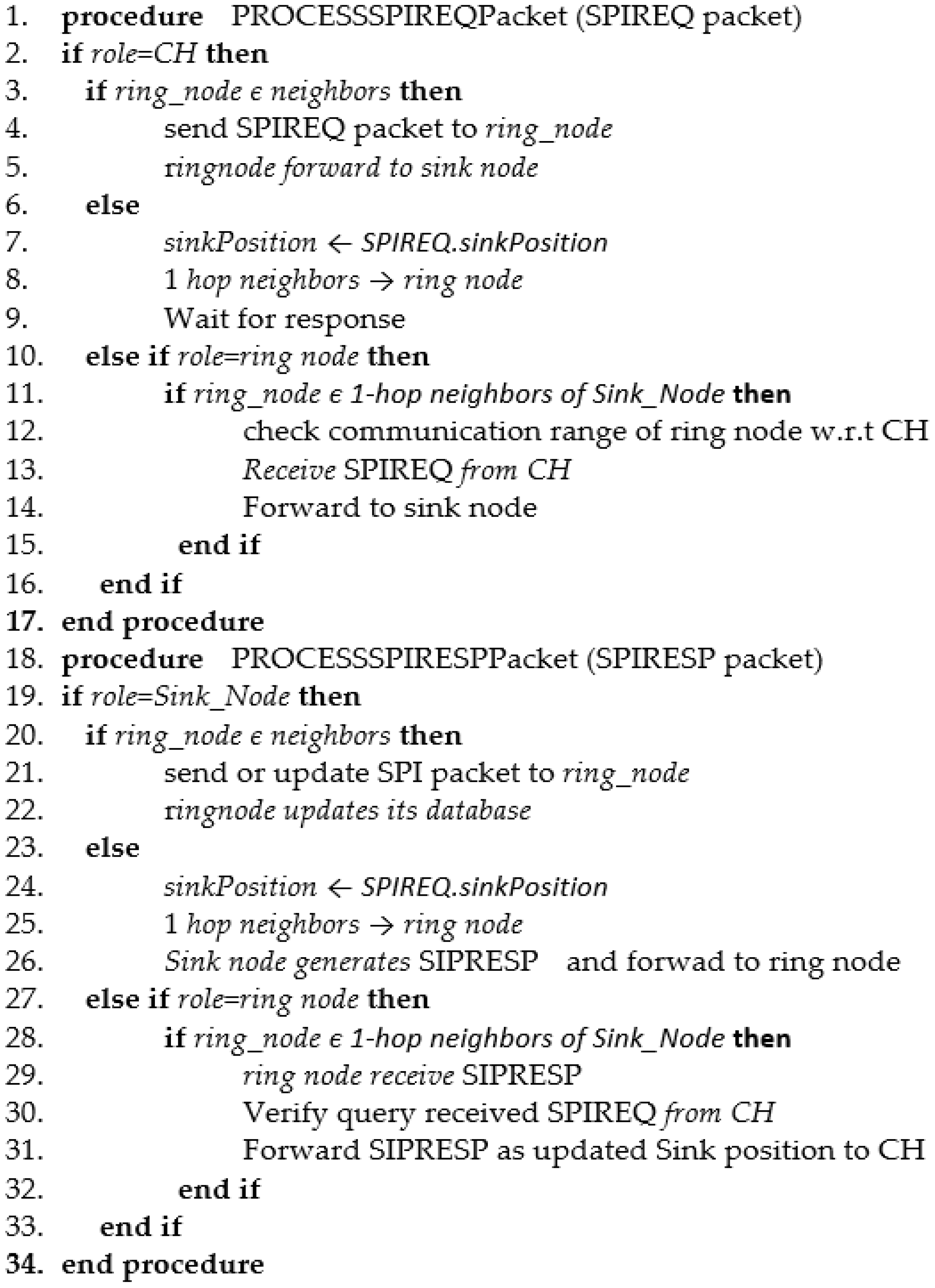
4.3. Determining the Ring’s Sink Position to the CH
Prior to disseminating the data, a
CH node that has data available from faraway nodes must determine the precise position of the sink node. The ring node has the most recent position of the sink node. A technique used to provide the SPI (sink position information) packets to the rings is utilized to retrieve it. The ring receives a SPIREQ (SPI request) packet from the CH and sends a SPIRESP (SPI response) packet back to the CH utilizing the CH position retrieved from the SPIREQ packet to make the request, via geographic routing. Once the CH has determined its location, it transfers the data packet in that direction. The pseudo codes of the methods to handle the SPIREQ and SPIRESP packets are given in
Figure 7.
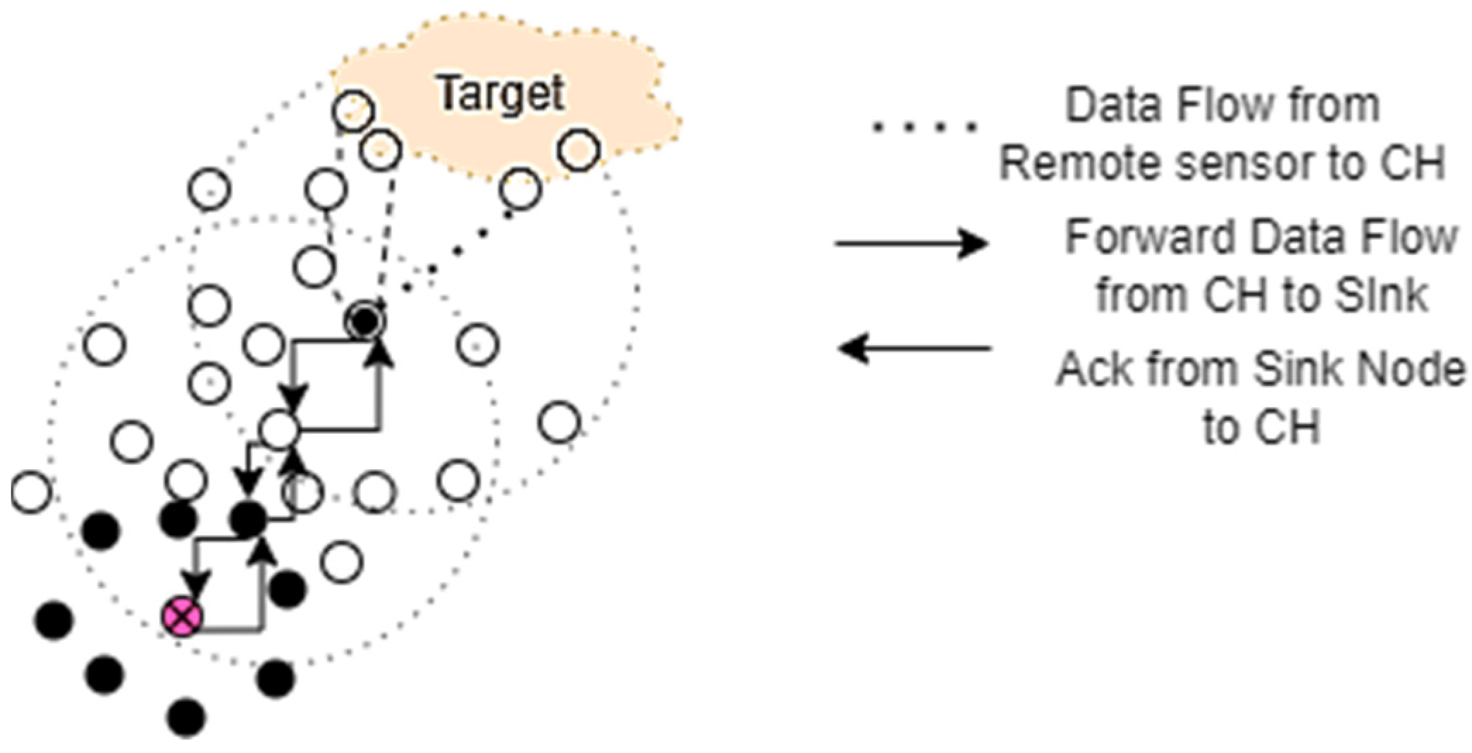
4.4. Data Dissemination
When a CH node receives a SPIRESP response to a SPIREQ request, it knows the location of the sink node and may then use geographic forwarding to deliver its data straight to it, as seen in
Figure 8. If the data arrive at an outdated sink node position, the sink node has changed by the time the data arrived. Because of this, the data are sent to the current sink node using a follow-up technique.
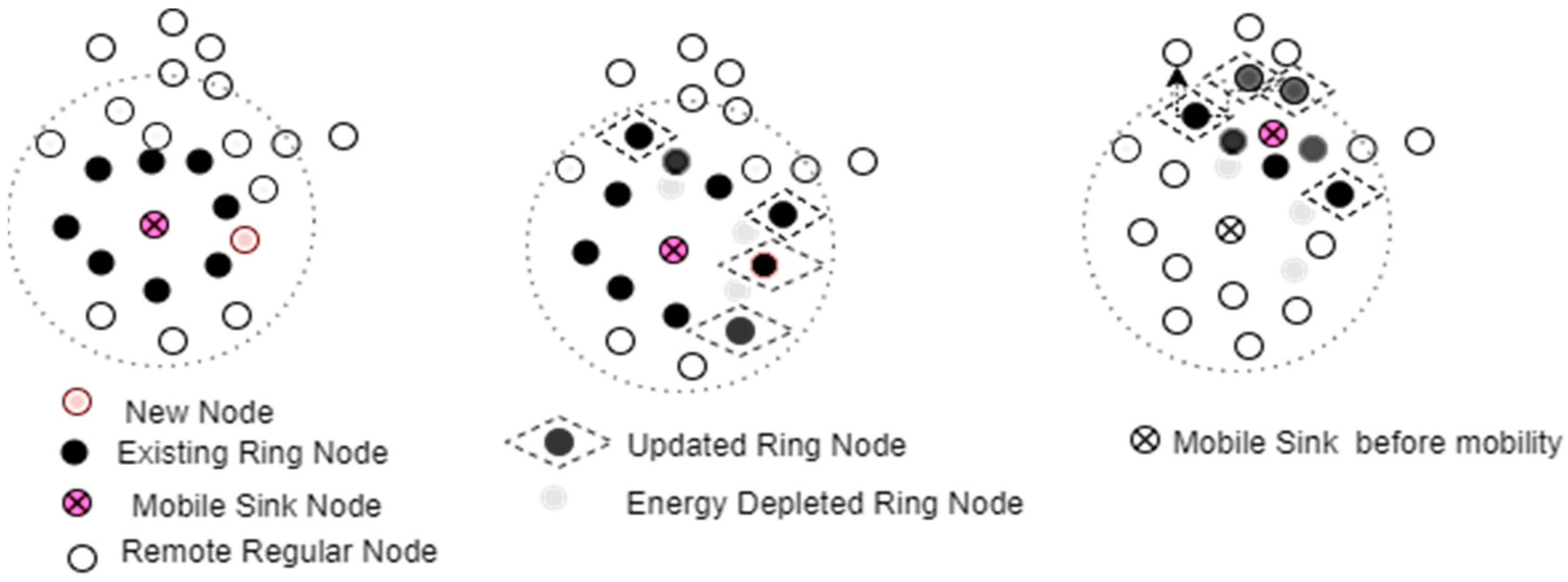
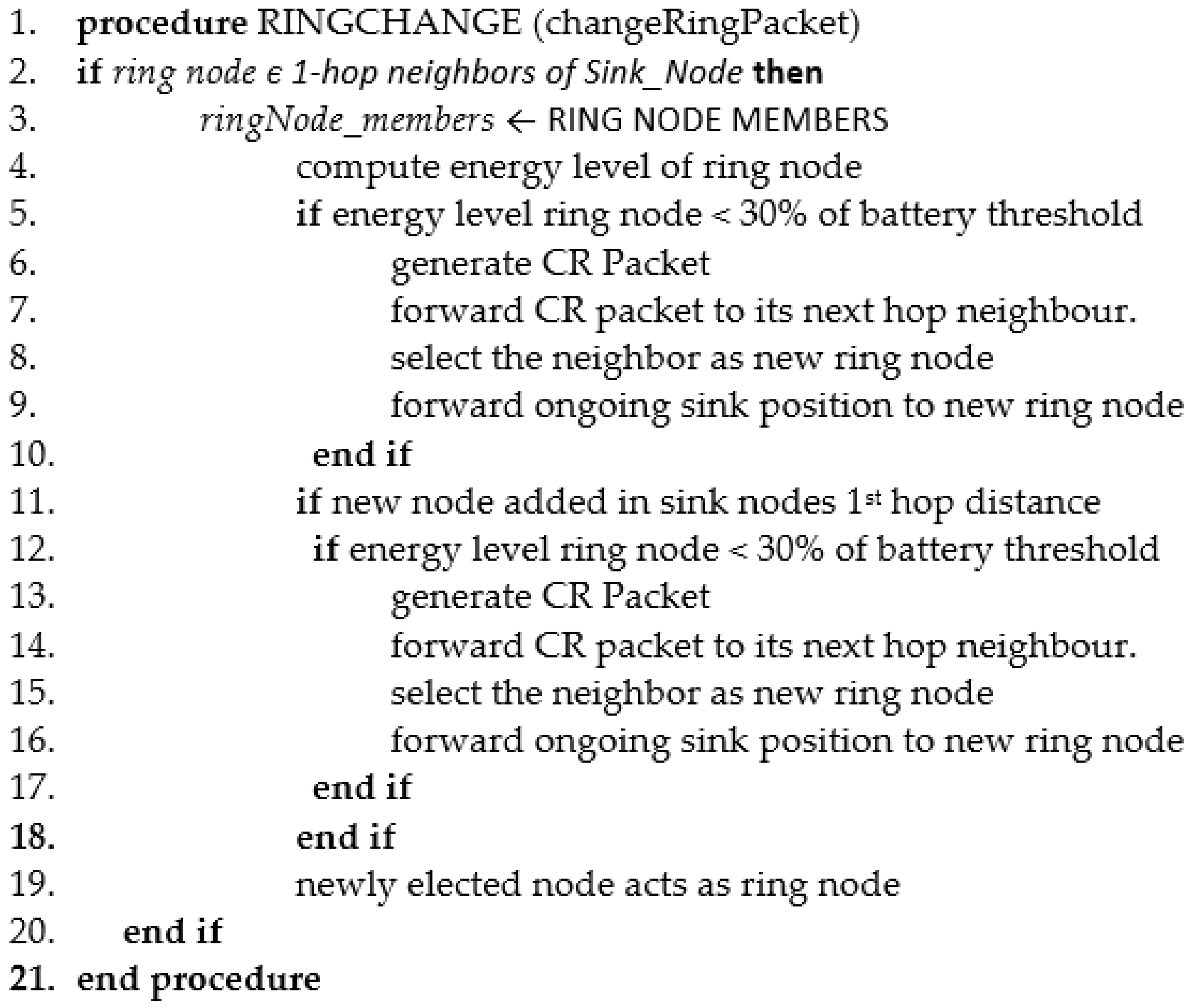
4.5. Ring Change
Ring nodes are more likely to use more energy than other distant nodes because they are more active in the sink position information advertisement and forwarding. They should switch roles on a routine basis since they manage more traffic than other remote nodes and risk dying prematurely. This mechanism of triggering might be a threshold at the battery level or it could occur regularly. However, replacing a battery in a remote area is difficult. Therefore, in such a scenario, two-hop neighbors of the sink node can be employed for an alternative purpose. The attributes of the ring node must be retained with the newly chosen ring node from the two-hop regular node or the new nodes introduced in that area in the one-hop neighbor of the sink node, as provided in
Figure 9. The ring node needs to send a broadcast CR (change ring) packet to another node in the network or a new node is added within its sensing range before its battery threshold level is reached. Similarly, a ring change also occurs when the movement of the sink occurs among the different points. In such a case, the ring node verifies the position of the sink after its mobility, within its sensing range or not. Beyond the sensing range, the node closer to the sink node receives the SPI packet from the sink and becomes ready for the ring node. In order to update its advertisement table with the most recent sink node data, the adjacent ring node transmits the CR packet to the newly chosen ring node. The pseudo code for the procedure is executed when the ring node chooses to alter its function, as depicted in
Figure 10.
5. Performance Evaluation
Extensive simulations are carried out using NS3 [
34] on Ubuntu 16.04 on a 64-bit operating system, Intel Core i5 Processor, 1.80 GHz frequency, and 16 GB RAM, in order to assess the performance of the modified ring routing. The simulation setup, the settings, and the metrics utilized for assessing the proposed routing, in comparison to the existing cutting-edge protocols [
35], are examined in this section. To remove the random nature of some simulation events, each scenario is also simulated 20 times with different seeds, yielding approximately 3600 simulations for the network density graphs and 1920 simulations for the mobility graphs.
5.1. Simulation Setup and the Performance Metrics
In this work, the time-sensitive periodic data reporting, utilizing the wireless sensor networks with mobile sinks is a major contender for the evaluation criteria, especially for the smart monitoring application. This is due to two aspects. First, because the routing protocol must effectively service the entire network, the periodic data applications necessitate the reporting of data from every node in the system. Second, the need to reduce the energy use and reporting delays for the time-sensitive applications, the time-sensitive application scenario is best for evaluating the effectiveness of the modified ring routing under these two constraints. The simulation parameters are discussed in
Table 2.
A topology of the different network densities as mentioned in the simulation parameters’ deployed sensor nodes in an area of 1000 × 1000 sqm is considered. A single sink, initially situated at the network center, that can move with a controlled mobility model in a constant speed, is simulated when the criteria is fulfilled. Again, the lifespan achieving tests are conducted and give the network convergence factors, based on node’s battery depletion.
We contrasted LBDD, MSRP, Mob M-LEACH, and the ring routing with our suggested modified ring routing method. To compare the performance of several algorithms equally, we executed the algorithms using the same network model. A packet’s throughput and the end-to-end delay [
36] metrics demonstrate how quickly it arrives at its destination, in comparison to the time needed for it to go there. It displays the quality of service the network provided. The energy use represents the energy that is still in the network after all operations have been completed. This contributes to the network lifespan that successfully carries out the application. The network convergence factor also calculates the network availability. Measuring the control overhead is a crucial metric for our investigation since it confirms the value of the ring building in the mobile sinks.
5.2. Result Analysis and Discussion
In our work, the analysis was conducted using several routing protocols and varying network densities and packet sizes.
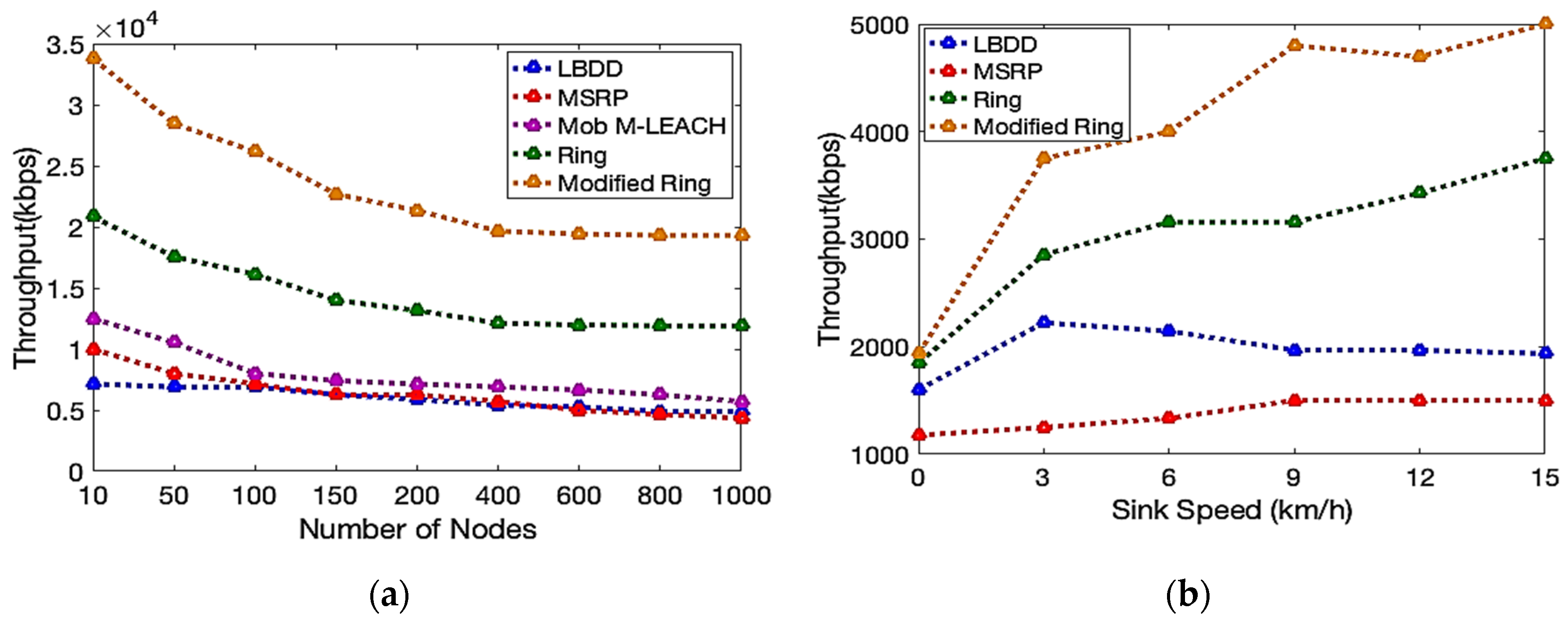
5.2.1. Throughput Analysis
Figure 11a, b illustrates the throughput analysis with the variations in the number of nodes and sink speeds. As compared to the other protocols, our proposed approach acquires the maximum effective packets. However, when the number of nodes increased, there was a slight decrease as a result of the increased control overhead and interference level that occurred with an increase in the node number. Again, compared to other protocols, the modified ring routing outperforms, which infers the use of the ring node for the sink advertisements, although it considers some overhead, but after the path is established, the data packets delivered are less prone to interference and packet loss. In
Figure 11b, the variation of the sink speed from the static level up to 15 km/h, shows an increase in the throughput level. The proposed ring routing also performs better in the throughput level than other protocols under the mobile sink. In LBDD and MSRP, the mobility of the sink occurs, which involves the data flow in a line or within a specified area, due to which even if the sink moves, the data is not received properly at the destination. However, in the ring routing, the construction itself consumes more time decreasing the throughput level even if sink is mobile. Therefore, the modified ring builds much faster the ring construction that helps in the frequent sink advertisement only to the CH, which involves the data retrieval and the dissemination at the CH in parallel, making the effective data delivery with the highly mobile sink node towards the CH.
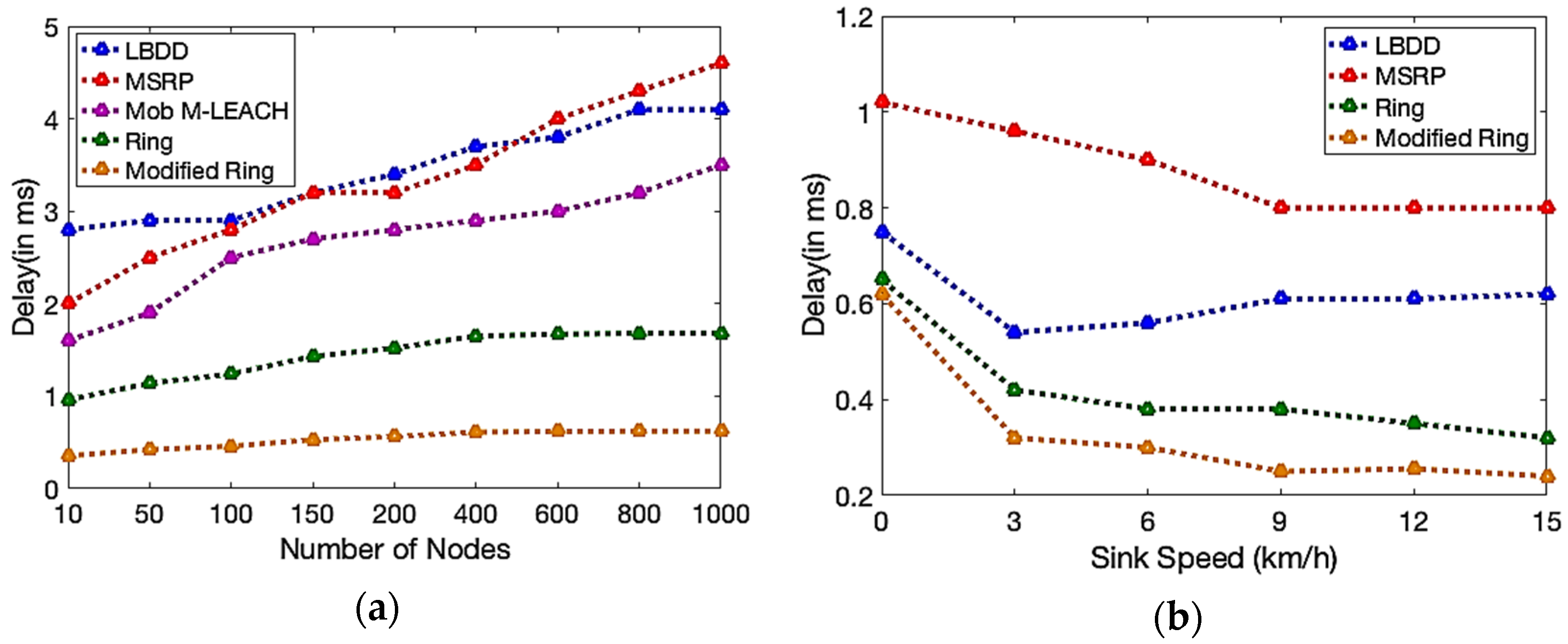
5.2.2. End-to-end Delay Analysis
The latency or end-to-end delay analysis discusses a faster data delivery of the network, which is one of the prime factors in monitoring the applications. The faster the information is revealed at the sink node, the more easily it is to prevent and execute the necessary action be taken at the target area. Keeping in mind that we analyzed the end-to-end delivery as the data holding time at each level of the nodes. As shown in
Figure 12a, b, the delay factor indicates the time a packet of data takes to reach the sink node from the target region. As the network size increases, the propagation delay of the nodes also increases, since it searches for the sink node every time the data needs to be delivered, which increases the delay in LBDD, MSRP and Mob M-LEACH, as given in
Figure 12a. However, the ring and the modified ring are based on the sink advertisement prior to the data delivery, due to the kinds of data held for a shorter amount of time in the respective nodes, thereby improving the data delivery time. Similarly, as shown in
Figure 12b, the static sink increases the delay, which is improved as and when the sink node moves towards the desired point and collects the data at a much faster rate. Again, the frequent sink advertisement by the ring node and the sink mobility makes the CH receive the data delivery more quickly, thereby justifying that our proposed ring routing is a better choice.
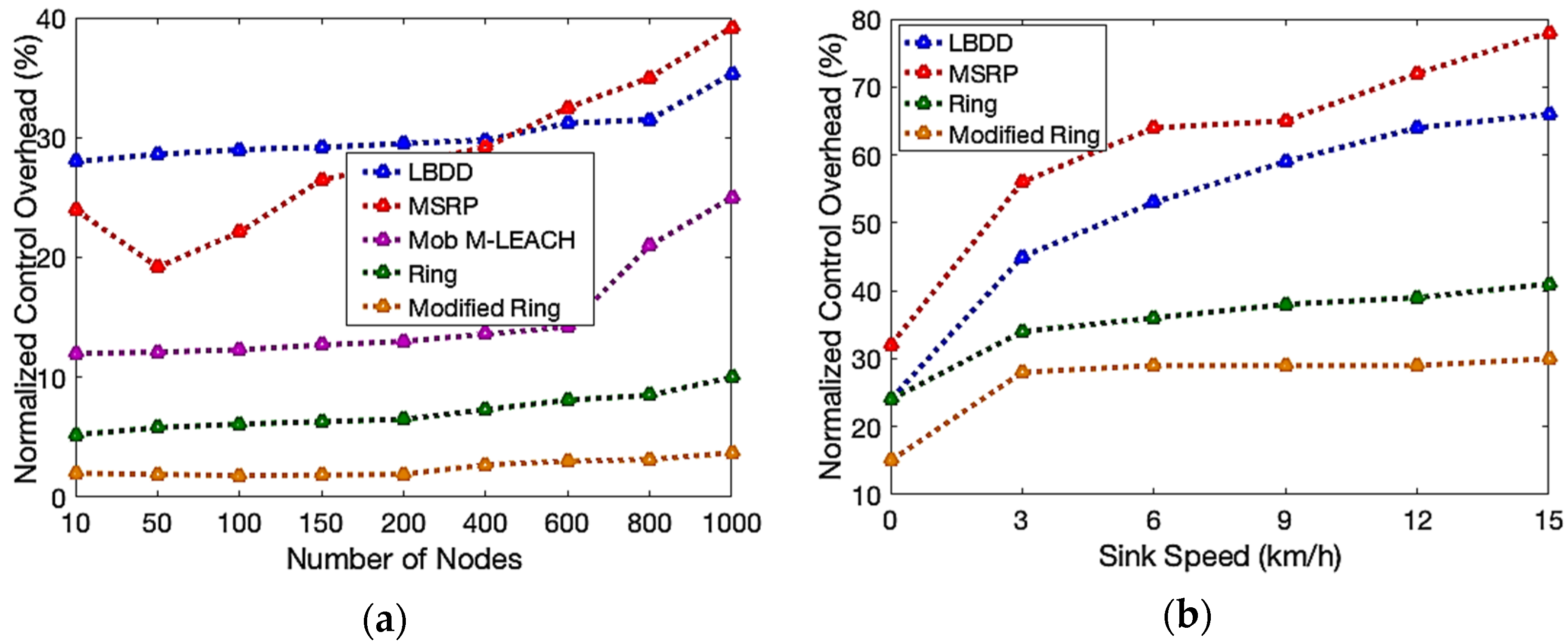
5.2.3. Control Overhead
The control overhead is another important parameter to analyze the effectiveness of our proposed work, as discussed in
Figure 13 a, b. The amount of control overhead remained relatively constant, even as the number of nodes increased, as seen by the network density fluctuation in
Figure 13a. However, the amount of overhead in the modified ring is less than the others, as the source and destination path is clear for the data delivery, in the first few rounds. Further, due to the movement of the sink node, the sink advertisement is easily conducted through the ring node only, rather than flooding it over the entire network. Under the static sink, the control overhead of the entire network is decreased, which increases as the mobility is introduced, as shown in
Figure 13b. The modified ring routing outperforms the other routing method of the ring routing, LBDD or MSRP, as they have a smaller number of control overhead packets.
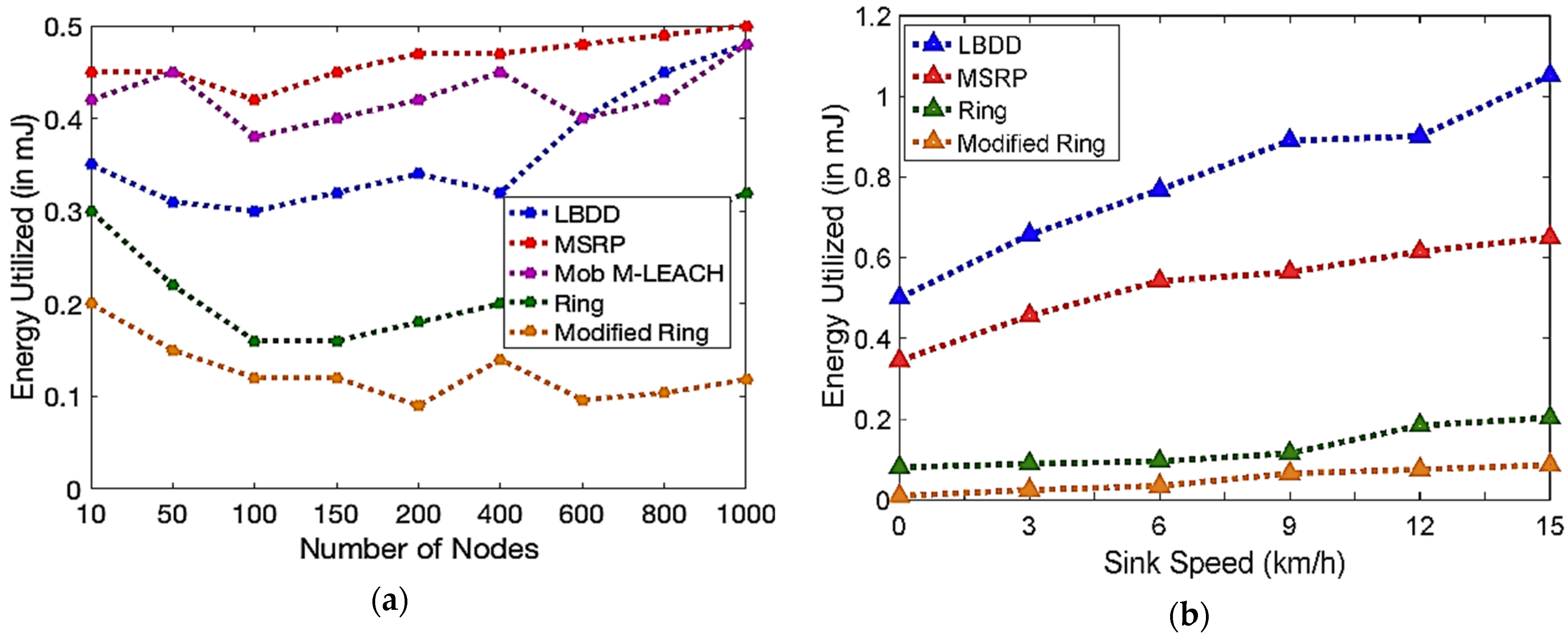
5.2.4. Energy Consumption Analysis
The amount of energy consumed by the network, as a whole, while using the routing protocol, as detailed in
Figure 14 a, b, is related to as the network’s energy consumption. Due to less control, the overhead packets are used, as well as the proper sink advertisements only, to the cluster head only, and none of the nodes are involved in knowing the sink position. Thus, less energy is consumed in the limited nodes, as compared to the involvement of the node’s energy utility in the other routing protocols, than the modified ring routing. So much less energy is consumed by the modified ring, in contrast to the other protocols, as shown in
Figure 14 a, even though the network density increases. As the sink node travels, relatively few nodes are also engaged, making the modified ring more energy efficient, as seen in
Figure 14b. It aids to prolong the entire network life, which enhances its appropriateness for the remote monitoring applications.
Thus, the overall analysis of the proposed model is summarized as the complexity analysis in
Table 3.
6. Conclusions
By taking into account the advantages and disadvantages of the pre-existing protocols described in the literature, we suggested a unique mobile sink routing protocol in this study, called modified ring routing. A logical ring is built around the sink node, which often advertises sinks, in this hierarchical heterogeneous network protocol. It is designed to make the information delivery much faster to the cluster head, about the mobile sink that mitigates the hotspot problem, observed in the static sink, and minimizes the data reporting delays, while taking the different mobile sink mobility characteristics into account. Again, this approach makes the data delivery much faster, with the help of clustering, especially for the smart monitoring applications. The extensive simulations are carried out to evaluate the performance of the modified ring routing and is implemented for a range of scenarios with different network capacities and sink speeds. The results indicate that the modified ring routing performs better than the ring, Mob M-LEACH, LBDD, and MSRP, in terms of energy consumption, extending the network’s lifespan, minimizing the control overhead, and enhancing the throughput.
In the future, we will modify the ring construction strategy, by applying the face routing concept and use multiple mobile sinks. It merely justifies the easy and fast data delivery. Therefore, the extensions and modifications to the modified ring routing needs to be justified against the extra costs and other effective mobility pattern utilization, to achieve a much better quality of service in the different application perspectives.


 ,
, 


