Article

Optimized Active Collision Avoidance Algorithm of Intelligent Vehicles

1
School of Electrical and Information Engineering, Zhongyuan University of Technology, Zhengzhou 450007, China
2
Department of Civil Engineering, Case Western Reserve University, Cleveland, OH 44106, USA
*
Authors to whom correspondence should be addressed.
Electronics 2023, 12(11), 2451; https://doi.org/10.3390/electronics12112451
Submission received: 4 May 2023 / Revised: 19 May 2023 / Accepted: 25 May 2023 / Published: 29 May 2023
(This article belongs to the Special Issue Positioning and Localization in UAV Networks/Flying Ad Hoc Networks)

Abstract

:
This research introduces an innovative strategy to impede and lessen lateral and rear-end vehicular collisions by consolidating braking systems with active emergency steering controls. This study puts forward a T-type active emergency steering method, designed to circumvent both lateral and rear-end collisions at vehicular intersections. To secure vehicular stability and condense the time required for steering during the T-type active emergency process, this research formulates a nonlinear dynamic model for the vehicle, in addition to a nonlinear tire model. This study also engages in a thorough analysis of the constraints linked to the initial and terminal states of the steering process. The issue at hand is articulated as an optimization control problem with boundary value restrictions, which is subsequently resolved using the Radau pseudospectral method. Simulation results corroborate that the prompt commencement of the anti-collision strategy can effectively deter potential collisions. This pioneering approach shows considerable promise in augmenting the active safety of intelligent vehicles and bears meaningful implications for high-precision automotive collision evasion systems.

1. Introduction

Vehicle collisions, particularly those involving fixed objects, pose a significant threat to the lives and well-being of drivers and passengers. Traditional passive safety systems, including seat belts, airbags, and bumpers, have been designed to mitigate the consequences of frontal collisions, significantly improving survival rates during accidents. However, with the advancement of technology, the focus has shifted towards active safety systems that enhance driving safety, handling, stability, ride comfort, and fuel economy [1]. Active safety technologies, such as Anti-lock Braking Systems (ABS), Traction Control Systems (TCS), Roll Stability Control (RSC), Collision Avoidance Systems (CAS), and Active Front Steering (AFS), aim to maintain vehicle stability under various driving conditions, including sideslip, overturning, and understeer [2,3].
ABS, the pioneering active safety technology, assists drivers in maintaining steering control and preventing excessive braking distances [4]. TCS helps maintain traction on diverse road conditions, such as dry, wet, icy, and snowy surfaces [5], while RSC decreases the risk of rollover accidents for passenger cars and light trucks [6]. AFS, on the other hand, enhances vehicle turning stability and overall performance [7]. CAS employs a range of sensors installed on the vehicle to monitor environmental changes and avert potential collisions [8]. Various types of sensors, including radar, laser, vision, ultrasonic, and global positioning, help detect objects around the vehicle and provide information to prevent or mitigate collisions by warning the driver, braking, or adjusting steering [9].
A key development in the automotive industry is the Intelligent Environment-Friendly Vehicle (i-EFV), which combines human–vehicle–road interaction to achieve multiple goals, such as traffic safety, energy optimization, and environmental protection [10]. The technology used in the avoidance assist system of emergency obstacles in i-EFV includes radar sensors and cameras in Advanced Driver Assistance Systems (ADAS), which communicate among vehicles to obtain information, such as detecting obstacles in the road environment [11]. Upon detecting a collision risk, the automatic controller compares the expected and actual vehicle paths, evaluates the accuracy of braking and steering, and activates avoidance interventions, including brake trigger collision, active front steering (AFS), electronic power steering (EPS), four-wheel steering (4WS), yaw moment control (YMC), and electronic stability control (ESC) [12]. This research on CAS in i-EFV holds particular significance [13].
For the dynamic path planning of intelligent vehicles, intelligent algorithms such as artificial potential field algorithm [14], neural network algorithm, genetic algorithm, etc. are also widely used. Most of the above algorithms are path planning for macro road network nodes. At present, the literature at home and abroad is less considering from the perspective of optimality, and further exploration and research are needed. There is a rectangular-shaped dark area below the vehicle, which has a smaller gray value compared to the road surface. This gray feature can be used to preliminarily detect the vehicle in front. Gradient shadow detection is commonly used for shadow detection [15], but it cannot effectively and accurately extract vehicle shadow information due to factors such as road impurities and building tree shadows. Previous studies have proposed various methods, models, algorithms, and strategies for collision avoidance systems and active safety technologies for intelligent vehicles [16,17,18,19]. These studies mainly focus on detecting and preventing collisions with vehicles or obstacles in front or behind the vehicle using sensors, actuators, controllers, and communication devices [20,21,22,23]. However, few studies have addressed the problem of side collision avoidance at intersections, where space for vertical and horizontal movement is limited [24,25,26]. Moreover, most of the existing methods rely on either braking or steering control separately or sequentially, which may not guarantee effective obstacle avoidance or vehicle stability when the distance between an intelligent vehicle and an obstacle is less than the minimum safe distance [27,28]. Therefore, this study aims to propose a novel approach that integrates braking and active emergency steering control for vehicles to prevent or mitigate side and rear-end collisions at crossroads. The proposed approach combines a nonlinear dynamic model for the vehicle and a nonlinear tire model with an optimization control problem with boundary value constraints. The Radau pseudospectral method is employed to solve the optimization control problem and generate collision avoidance control commands. The proposed approach is expected to achieve anti-collision in the shortest time while ensuring vehicle stability and maneuverability.
This paper proposes a T-type active emergency steering strategy to address side collision avoidance at intersections, where space for vertical and horizontal movement is limited. By combining braking and active emergency steering, this strategy aims to prevent or reduce the consequences of collisions. The problem is transformed into a time optimization control problem with boundary value constraints to ensure vehicle stability and minimize steering time during the T-type active emergency steering process. The vehicle’s nonlinear dynamics model and nonlinear tire model are established, along with the starting and ending state constraints of the T-type active emergency steering. The Radau pseudospectral method is used to solve the optimization control problem, and a double T-type active emergency steering control is employed to prevent rear-end collisions. Simulation results verify the effectiveness of the proposed strategy, highlighting its contribution to the research on collision avoidance systems for intelligent vehicles and emphasizing the importance of active safety technologies in modern automotive development.
Recent advancements in vehicle lateral obstacle avoidance technology have also emerged as one of the critical components of intelligent vehicles [29]. Some studies propose lateral active collision avoidance systems for electric vehicles based on fuzzy sliding mode control [30]. By analyzing the mechanism and influencing factors of side collision risk of a vehicle [31], these developments in collision avoidance systems and active safety technologies, coupled with the continuous growth of autonomous vehicle research, hold great promise for the future with significantly reduced traffic accidents, enhanced vehicle performance, and improved road safety. As vehicles become increasingly intelligent and interconnected, new opportunities arise for the development and implementation of innovative safety systems that will revolutionize the automotive industry.
In conclusion, the proposed T-type active emergency steering strategy contributes to the ongoing research and development of active safety technologies and collision avoidance systems for intelligent vehicles. By addressing the limitations of current active safety designs and proposing a novel approach to side collision avoidance at intersections, this study emphasizes the importance of integrating vehicle systems, sensors, and drivers to create a safer driving environment. This research not only highlights the potential for advancements in intelligent vehicle technology but also underscores the significance of continued innovation in active safety systems to ensure a more secure and efficient transportation landscape.

2. Anti-Collision T-Type Active Emergency Steering Control Strategies

The selection of the single-T and double-T anti-collision strategies, aimed at preventing side and rear-end collisions, respectively, is informed by their prevalence in real-world scenarios as highlighted by crash data. Given their representation of the majority of vehicular accidents, they merit focused investigation. The study, illustrated in Figure 1 and Figure 2, explores these active emergency steering control strategies, showcasing the vehicle’s reference trajectory and posture before and after steering. In the figures, A, B, C, D, and E depict vehicles within the lane. The study’s primary objective is to address the time-optimization problem intrinsic to T-type active emergency steering.

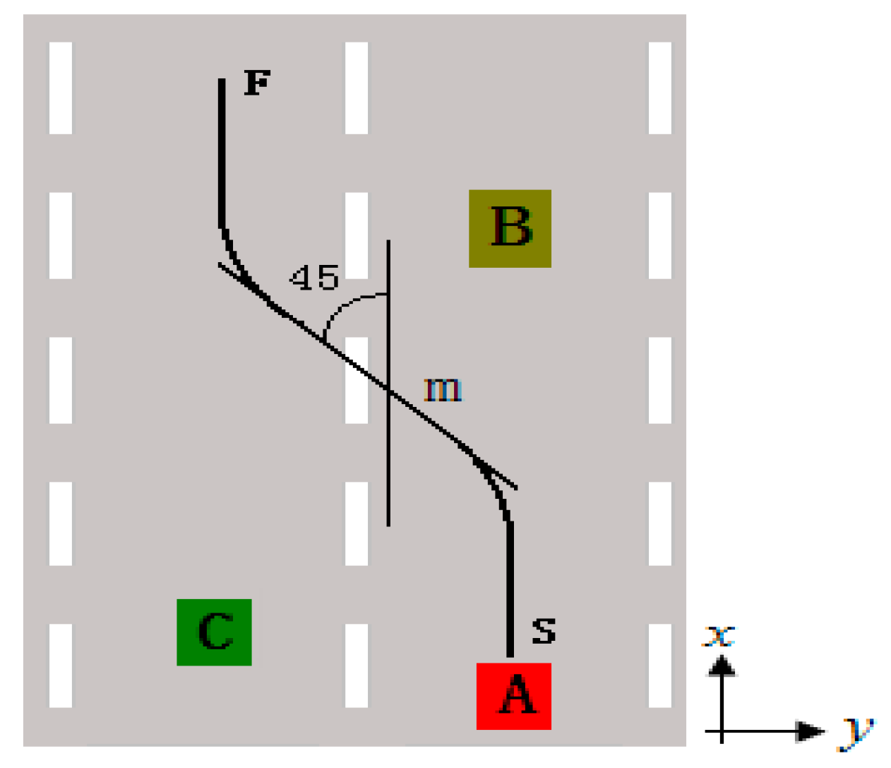
2.1. Single T-Type Emergency Steering for Preventing Side Collision at Crossroads

Figure 1 illustrates the single T-type active emergency steering strategy for preventing side collisions at crossroads. In the figure, A, B, C, D, and E represent vehicles in the lane. Taking vehicle A as an example, both vehicles A and C obey traffic rules and intend to pass a traffic intersection. If there is an imminent collision risk between vehicles A and C, vehicle A must perform active steering control to avoid colliding with vehicle C. Points S and F are the starting and endpoints of vehicle A, respectively. As per the coordinate system in Figure 1, the heading angle of the vehicle at point S is 0 degrees and at point F is 90 degrees. Thus, to complete the anti-collision T-type active emergency steering, vehicle A must brake and execute a 90-degree turning control in the shortest time.

2.2. Anti-Collision: Double-T Emergency Steering Strategy

Figure 2 demonstrates the anti-collision double-T active emergency steering strategy, with A, B, and C representing vehicles in the lane. Taking vehicle A as an example, if there is an unavoidable rear-end collision between vehicle A and vehicle B, active steering control of vehicle A must be performed. The steering path in Figure 2 completes the anti-collision control from point S to point F through point m, encompassing two T-shaped steering controls. The path from point S to point m is a left turn T-shaped steering control, while the path from point m to point F is a right T-shaped steering control. According to the coordinate system in Figure 2, the vehicle’s heading angle at point S is 0 degrees, at point m is −45 degrees, and at point F is 0 degrees, completing the anti-collision active emergency steering control. Vehicle A achieves two T-turn steering controls in the shortest time following a straight driving period after braking.

3. Simplified Single Traction Bicycle Model

The vehicle dynamic model utilized in this study is a simplified single traction bicycle model [32], which encompasses three degrees of freedom: longitudinal motion, lateral motion, and yaw motion (Figure 3). Its dynamic differential equation is
u ˙ = 1 m ( F x f cos ( δ ) F y f sin ( δ ) + F x r ) + v r v ˙ = 1 m ( F x f sin ( δ ) + F y f cos ( δ ) + F y r ) u r r ˙ = 1 I z ( l a ( F x f sin ( δ ) + F y f cos ( δ ) ) l b F y r ) ψ ˙ = r
ω ˙ f = 1 I ω ( T b f F x f R ) ω ˙ r = 1 I ω ( T b r F x r R )
x ˙ = u cos ( ψ ) v sin ( ψ ) y ˙ = u sin ( ψ ) + v cos ( ψ )
Equation (1a) is the motion dynamics equation. State vector X = [ u , v , r , ψ , ω f , ω r ] T ; u is the longitudinal speed; v is the lateral speed; r is the yaw rate; ψ is the heading angle of the vehicle; ω f and ω r are the angular velocity of the front and rear wheels; x and y are the longitudinal and lateral coordinates of the earth coordinate system of the vehicle mass center; I z is the vehicle yaw moment of inertia; m is the mass of the entire vehicle; R is the effective radius of the wheel; l a and l b are the distance from the mass center of the entire vehicle to the front and rear axles; and δ is the road-wheel angle.
Equation (1b) is the differential equation of front and rear wheel rotation. T b f and T b r are the front and rear wheel moments, respectively. I ω is the rotational moment of inertia of each tire. Here, T b f and T b r , respectively, are
T b f = { ( 1 γ b ) T b , ω f > 0 F x f R , ω f = 0
T b r = { γ b T b T h b , ω r > 0 F x r R , ω r = 0
In Equations (2) and (3), T b is the conventional braking torque; T h b is the hand brake braking torque; and γ b is the ratio of the front and rear wheel braking torque, γ b ( 0 , 1 ) . The conventional braking torque T b acts on the front wheels and the rear wheels, respectively, in proportion γ b —that is, T f / T r = ( 1 γ b ) / γ b , the handbrake braking torque T h b only acts on the rear wheels. When ω j > 0 ( j = f , r )—that is, the angular velocity of the vehicle is non-zero— T b j ( j = f , r ) is equivalent to the torque generated by the braking mechanism; when ω j = 0 ( j = f , r )—that is, the wheels are locked— T b j ( j = f , r ) is independent of brake pressure.
In Formulas (1)–(3), F i j ( i = x , y ; j = f , r ) is the longitudinal force and the lateral force. These forces depend on the load acting on the front axle F z f and the rear axle F z r , as well as the longitudinal and lateral slip rates. The anti-collision emergency steering involves a larger slip angle, and the magic tire model is selected. The tire force of the model is expressed as a transcendental function of slip rate [33].
F i j ( i = x , y ; j = f , r ) F i j = μ F z j μ i j
In Formula (4), μ is the tire-road friction coefficient.
μ i j = s i j s j sin ( C arctan ( B s j ) ) F z f = m g l b μ h m g μ x r l a + l b + μ h ( μ x f cos ( δ ) μ y f sin ( δ ) μ x r ) F z r = m g F z f
In Formula (5), s i j ( i = x , y ; j = f , r ) is the slip rate, which is s x j = V x j ω j R ω j R , s y j = V y j V x j ( 1 + s x j ) , s j = s x j 2 + s y j 2 , j = f , r .
In the above formula, V i j ( i = x , y ; j = f , r ) is
V x f = u cos ( δ ) + v sin ( δ ) + r l a sin ( δ ) V y f = u sin ( δ ) + v cos ( δ ) + r l a cos ( δ ) V x r = u V y r = v r l b

4. Optimization Control Problem for Anti-Collision Active Emergency Steering

To achieve the anti-collision active emergency steering control depicted in Figure 1 and Figure 2, it is necessary to complete the steering operation in the shortest time possible. Consequently, the anti-collision active emergency steering control in Figure 1 and Figure 2 is transformed into a shortest-time optimal control problem (OCP) with constraints. The objective function for anti-collision active emergency steering is
J = 0 t f d t = t f
where t f is the end time of steering control, i.e., the driving time at point F. The anti-collision active emergency steering control in Figure 1 and Figure 2 requires t f to be minimal.
Assume the time at the starting point S is t 0 , the starting point state is X 0 = [ u 0 , v 0 , r 0 , ψ 0 , ω f 0 , ω r 0 ] T ; the time at the endpoint F is t f , the end state is X f = [ u f , v f , r f , ψ f , ω f f , ω r f ] T . The time at the midpoint m is t m , and the midpoint state is X m = [ u m , v m , r m , ψ m , ω f m , ω r m ] T . In Figure 1, take X 0 = [ V 0 , 0 , 0 , 0 , V 0 / R , V 0 / R ] T and ψ f = π / 2 , and others are not specified. In Figure 2, the starting point S to the midpoint m section, X 0 = [ V 0 , 0 , 0 , 0 , V 0 / R , V 0 / R ] T and ψ m = π / 4 ; the midpoint m to the end point F section, and the end state after the execution of the point S to the point m section is X m , among them , ψ m = π / 4 and ψ f = 0 .
In Equation (1), to accomplish the anti-collision steering control, the control vector is u = [ δ , T b , T h b ] T . The control vector u is limited by the vehicle configuration components’ physical parameters, and the control vector constraint condition is
δ min δ ( t ) δ max 0 T b ( t ) T b max 0 T h b ( t ) T h b max
δ max = 40 , δ max = 40 , T b max = 948 N m , T h b max = 380 N m . Similarly, the constraint condition of the state vector X in Formula (1) is
X * min X * X * max
In Equation (8), * [ u , v , r , ψ , ω f , ω r ] .
Considering Equations (1) through (8), the anti-collision emergency steering control problem in Figure 1 is transformed into a constrained shortest-time optimal control problem, which is
min J = 0 t f d t = t f
  • s.t.
  • Vehicle model constraints: Equation (1)
  • State constraints: Equation (8)
  • Control vector constraints: Equation (7)
  • Boundary value constraints:
u ( 0 ) = V 0 , v ( 0 ) = 0 , r ( 0 ) = 0 , ψ ( 0 ) = 0 , ω f ( 0 ) = V 0 / R , ω r ( 0 ) = V 0 / R , ψ ( t f ) = 90 °
Likewise, the anti-collision double-T-type active emergency steering control problem in Figure 2 is divided into two single-T-type emergency steering control problems. Equation (9) can be referenced for this purpose.

5. Radau Pseudospectral Method

5.1. Solving Steps Based on the Radau Pseudospectral Method

First, the optimization control problem concerning the shortest anti-collision time is formulated as a Mayer-type objective function optimization control problem [34]. The continuous Mayer problem is an optimization control problem described by Equations (11)–(13) [33].
min J = Φ ( X ( τ f ) )
s.t.
d X d t = t f t 0 2 f ( X ( τ ) , U ( τ ) ) n
ϕ ( X ( τ 0 ) , X ( τ f ) ) = 0 q
where X ( τ ) n is the system state vector; U ( τ ) m is the system control vector; t 0 is the start time; t f is the terminal time; ϕ ( X ( τ 0 ) , X ( τ f ) ) is the terminal constraint condition; f ( X ( τ ) , U ( τ ) ) is the system’s differential equation constraint; J is the Mayer-type objective function. To reduce the computational load, the terminal time t f is set here replacing the algebraic path constraint. Mayer time interval τ [ 1 , 1 ] , optimal control time interval t [ t 0 , t f ] , and the conversion relationship between τ and t is
t = t f t 0 2 τ + t f + t 0 2
Thus, for the optimization control problem concerning the shortest anti-collision time, take the state variable X = [ u , v , r , ψ , ω f , ω r ] T , take the control vector u = [ δ , T b , T h b ] T , take J as the Equation (6), take f ( . ) as the Equation (1), and take ϕ ( . ) as the Equation (10). This way, the optimization control problem with the shortest anti-collision time is summarized as a Mayer-type objective function optimization control problem.
The shortest anti-collision time optimization problem based on the Radau pseudospectral method is transformed into an NLP problem subject to a series of algebraic constraints [35]. Finally, the Sequential Quadratic Programming (SQP) algorithm is employed to solve the NLP problem [36].

5.2. GPOPS Software Solution

The GPOPS-II software is utilized to solve the problem [37], and defined function files are written in the MATLAB environment, which mainly includes
(1) The primary function file AntiCollision
Main.m, which encompasses the equality and inequality constraints of design variables (state, control, path), sets the initial values of the variables, specifies the differentiation strategy employed in the derivation process, and provides grid optimization information.
setup.name = ‘OptimalAntiCollision’;
setup.limits = limits;
setup.guess = guess;
setup.funcs.cost = ‘AntiCollisionCost’;
setup.funcs.dae = ‘AntiCollisionDae’;
setup.linkages = [];
setup.derivatives = ‘finite-difference’;
setup.autoscale = ‘on’;
setup.mesh.tolerance = 8 × 10³
setup.mesh.iteration = 4;
setup.mesh.nodesPerInterval.min = 4;
setup.mesh.nodesPerInterval.max = 12;
[output,gpopsHistory] = gpops(setup);
(2) According to Equation (9), write the target function file AntiCollisionCost.m. The main codes include
Mayer = tf;
(3) According to Equation (1), write the differential algebraic equation (DAE) file AntiCollisionDae.m. The main codes include
du = (1/m).*(Fxf.*cos(delt)-Fyf.*sin(delt) + Fxr) + v.*r;
dv = (1/m).*(Fxf.*sin(delt) + Fyf.*cos(delt) + Fyr)-u.*r;
dr = (1/Iz).*(lf.*(Fxf.*sin(delt) + Fyf.*cos(delt))-lr.*Fyr);
dfi = r;
dx = u.*cos(fi)-v.*sin(fi);
dy = u.*sin(fi) + v.*cos(fi);
dwf = (tTbf-Fxf.*R)./Iw;
dwr = (Tbr-Fxr.*R)./Iw;
dae = [du dv dr dfi dwf dwr].

6. Numerical Simulation Results

To verify the anti-collision T-type active emergency steering control strategy, simulation research is conducted. This paper processes the code running results in Section 5.2 and presents the simulation outcomes. The parameter values of the vehicle and tire used are listed in Table 1.

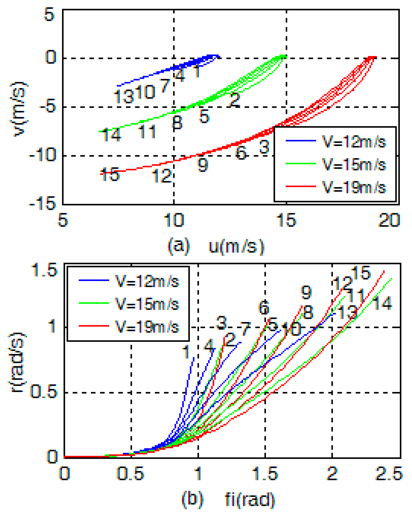
6.1. Phase Plan of Each State

Considering initial vehicle speeds of 12 m/s, 15 m/s, and 19 m/s; conventional braking torques of 0, 200 Nm, 300 Nm, 400 Nm, and 500 Nm; and parking brake torques of 0, 100 Nm, 200 Nm, 300 Nm, and 400 Nm; the phase portrait of each state is obtained through simulation, as illustrated in Figure 4. Figure 4 shows the phase plan analysis of various initial vehicle speeds and braking torques for the anti-collision T-type emergency steering control strategy. The figure consists of four subplots, each depicting the relationship between two state variables: longitudinal speed and lateral speed, heading angle and yaw rate, front wheel angular velocity and rear wheel angular velocity, and longitudinal coordinate and lateral coordinate. Figure 4a displays u v the phase portrait; Figure 4b shows the ψ r phase portrait; Figure 4c presents the ω f ω r phase portrait; and Figure 4d reveals the x y phase portrait.

6.2. Crossroad Anti-Side-Collision T-Type Emergency Steering

The simulation results of anti-collision T-type emergency steering at crossroads with three different initial vehicle speeds are displayed in Figure 5. The figure consists of six subplots, each depicting the relationship between one state variable and time: longitudinal speed, lateral speed, yaw rate, heading angle, front wheel angular velocity, and rear wheel angular velocity. The figure demonstrates how the state variables vary over time as the vehicle completes the T-type steering control under different initial speeds. Figure 5a demonstrates the relationship between longitudinal speed and time. Figure 5c indicates that the vehicle completes the T-turn at the maximum yaw rate. The vehicle’s final heading angle in Figure 5d is 1.57 rad (90°), which completes the 90° steering.
Figure 6a illustrates the relationship between wheel angle and time. Figure 6d reveals that the vehicle’s trajectory is turning right by 90°. Figure 5 and Figure 6 indicate that the minimum time to complete the T-type emergency steering is different at various initial vehicle speeds. The higher the initial vehicle speed is, the longer the turning time and the greater the vehicle travel distance are. The simulation results of the control variables are displayed in Figure 6. Figure 6b shows that conventional braking is in effect during the initial and final stages. Figure 6c demonstrates that the handbrake is fully functional at the initial stage. Figure 5f indicates that the rear wheels are almost locked, and the rear wheel angular velocity is significantly reduced. This leads to a deliberate loss of rear-wheel traction, often utilized by experienced drivers to initiate and maintain the vehicle’s rotational yaw operation. In this manner, the rear wheels are intentionally saturated, causing the force acting on the rear axle of the vehicle to disappear and resulting in an unstable factor that prompts rapid yaw rotation.

6.3. Anti-Collision Double-T-Type Emergency Steering

The simulation results of the anti-collision double-T-type steering with three different initial vehicle speeds are presented in Figure 7 and Figure 8. In these figures, the “o” point corresponds to the “m” point in Figure 2, representing the midpoint of two single T-turns. This strategy is used to prevent rear-end collisions by performing two consecutive 45-degree turns in opposite directions. The curve of each color in the figures signifies an initial vehicle speed. In Figure 7d, the vehicle’s heading angle at the initial position is 0 degrees; the heading angle at the midpoint is −45 degrees; and the heading angle at the endpoint is 0 degrees, indicating that the vehicle has completed two T-turn controls. Figure 8d displays the driving trajectory of the vehicle with double-T-type steering. The higher the initial vehicle speed, the greater the longitudinal travel distance of the vehicle.
In summary, the simulation results validate the effectiveness of the proposed anti-collision-T-type and double-T-type active emergency steering control strategies. The simulations demonstrate that the control strategies can successfully navigate the vehicle through various emergency scenarios, taking into account different initial speeds and braking torques. These strategies provide a foundation for further development and optimization of intelligent vehicle systems to enhance safety and performance in real-world driving situations.

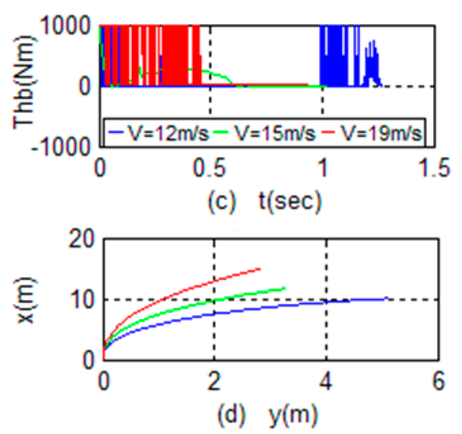
6.4. Analysis of Anti-Collision-T-Type Steering Control Results

Table 2 presents the initial vehicle speed, final vehicle speed, initial heading angle, final heading angle, and steering end time (optimization time) values. The initial and final heading angle values indicate that the vehicles successfully complete their respective T-type steering control. The optimization time listed in Table 2 represents the minimum time required to complete the steering. Sensor devices can detect the positional relationship with the vehicle ahead and determine whether to activate T-type active emergency steering control. Millimeter-wave radar or LiDAR can be utilized to sense the vehicle in front and its location. Considering that the vehicle’s initial speed is not zero, the safe distance that can prevent a collision through normal braking should be calculated. If a collision cannot be avoided through normal braking, T-type active emergency steering control should be activated. The safety distance is typically calculated based on the maximum possible deceleration.
As depicted in Figure 9, zone Z1 (green) is a safe zone where normal braking can prevent collisions. Zone Z2 (red) represents the smallest area where normal braking is guaranteed not to collide. If the vehicle is in zone Z2, normal braking cannot avoid collisions. Zone Z3 (yellow) is the longitudinal distance of the anti-collision-T-type active emergency steering. In the Z2–Z3 zone, the strategy presented in this paper can be employed to prevent collisions. In other words, it is only in zone Z2 that the strategy can effectively prevent collisions, while in zone Z1, it is not necessary to initiate the strategy. As seen in Figure 9, the sizes of Z1, Z2, and Z3 vary with different initial vehicle speeds.
As shown in Figure 10, the simulation results of the proposed algorithm closely align with the theoretical predictions, proving that the algorithm has a certain degree of practicability.

7. Conclusions

In this study, a combined braking and T-type active emergency steering control method is proposed to address side and rear-end collisions at crossroads. Previous literature has focused on lateral active obstacle avoidance algorithms in scenarios involving three-corner collisions, side collisions, and friction collisions between two vehicles traveling in the same direction. The core of these algorithms is the Time to Collision (TTC), which is calculated based on the vehicle’s distance and speed. However, these algorithms do not account for the necessary control of the vehicle during the implementation of lateral obstacle avoidance.
In contrast, the current research analyzes the nonlinear dynamic model, tire model, and starting and ending state conditions of the vehicle, offering a more comprehensive approach than previous studies. The anti-collision problem is transformed into the shortest time-optimal control problem, and the Radau pseudospectral method is employed to solve the anti-collision optimization control problem, ensuring stability and the shortest time for a vehicle with T-type active emergency steering. The proposed strategy can prevent collisions or reduce their consequences through braking and active steering.
Compared to existing anti-collision methods, the strategy presented in this study integrates vehicle dynamics and optimization control problems to achieve anti-collision. This approach actively changes the vehicle’s position and posture to avoid or mitigate collisions. Future research will aim to implement the optimization control technology presented in this study in real-time, considering uncertain factors such as friction coefficient, mass, moment of inertia, and center of gravity to generate collision avoidance control commands. This work has significant implications for enhancing the active safety and practical application of intelligent vehicles.

Author Contributions

Q.X. and X.L.: conceptualization, methodology, software, validation; Q.X. X.L. and J.X.: formal analysis, investigation, data curation, writing—original draft preparation; J.X. and Q.X.: conceptualization, writing—review and editing, visualization, funding acquisition. All authors have read and agreed to the published version of the manuscript.

Funding

This work was supported in part by the National Natural Science Foundation of China under grants 61379113, Henan science and technology innovation team under grant CXTD2017091, and Science and Technology Innovation Team of Colleges and Universities in Henan Province under grant 18IRTSTHN013.

Institutional Review Board Statement

Not applicable.

Informed Consent Statement

Not applicable.

Data Availability Statement

The data presented in this study are available on request from the corresponding author.

Acknowledgments

We are grateful to two anonymous reviewers for their constructive comments.

Conflicts of Interest

The authors declare no conflict of interest. The funders had no role in the design of the study; in the collection, analyses, or interpretation of data; in the writing of the manuscript; or in the decision to publish the results.

References

  1. Anderson, J.; Kalra, N.; Stanley, K.; Sorensen, P.; Samaras, C.; Oluwatola, O. Autonomous Vehicle Technology: A Guide for Policymakers; RAND Corporation: Santa Monica, CA, USA, 2016; ISBN 978-0-8330-8398-2. [Google Scholar]
  2. Gandhi, T.; Trivedi, M.M. Vehicle Surround Capture: Survey of Techniques and a Novel Omni-Video-Based Approach for Dynamic Panoramic Surround Maps. IEEE Trans. Intell. Transp. Syst. 2006, 7, 293–308. [Google Scholar] [CrossRef]
  3. Sandu, C. Vehicle Dynamics: Theory and Applications. J. Guid. Control. Dyn. 2010, 33, 287–288. [Google Scholar] [CrossRef]
  4. Anderson, R.; Hutchinson, T.; Linke, B.; Ponte, G. Analysis of Crash Data to Estimate the Benefits of Emerging Vehicle Technology; Centre for Automotive Safety Research, The University of Adelaide: Singapore, 2010. [Google Scholar]
  5. Saha, S.; Amrr, S.M. Design of Slip-Based Traction Control System for EV and Validation Using Co-Simulation between Adams and Matlab/Simulink. Simulation 2020, 96, 537–549. [Google Scholar] [CrossRef]
  6. Yih, P.; Ryu, J.; Gerdes, J.C. Modification of Vehicle Handling Characteristics via Steer-by-Wire. In Proceedings of the 2003 American Control Conference, Denver, CO, USA, 4–6 June 2003; Volume 3, pp. 2578–2583. [Google Scholar]
  7. Fujita, Y.; Tsuchiya, Y.; Suzumura, M.; Kojo, T. Development of Active Front Steering Control System; SAE International: Warrendale, PA, USA, 2005. [Google Scholar]
  8. Baek, M.; Jeong, D.; Choi, D.; Lee, S. Vehicle Trajectory Prediction and Collision Warning via Fusion of Multisensors and Wireless Vehicular Communications. Sensors 2020, 20, 288. [Google Scholar] [CrossRef] [PubMed]
  9. Koopman, P.; Wagner, M. Autonomous Vehicle Safety: An Interdisciplinary Challenge. IEEE Intell. Transp. Syst. Mag. 2017, 9, 90–96. [Google Scholar] [CrossRef]
  10. Chen, Y.; Chen, S.; Ren, H.; Gao, Z.; Liu, Z. Path Tracking and Handling Stability Control Strategy With Collision Avoidance for the Autonomous Vehicle Under Extreme Conditions. IEEE Trans. Veh. Technol. 2020, 69, 14602–14617. [Google Scholar] [CrossRef]
  11. Li, K.; Chen, T.; Luo, Y.; Wang, J. Intelligent Environment-Friendly Vehicles: Concept and Case Studies. IEEE Trans. Intell. Transp. Syst. 2012, 13, 318–328. [Google Scholar] [CrossRef]
  12. Guo, J.; Chu, L.; Liu, H.; Shang, M.; Fang, Y. Integrated Control of Active Front Steering and Electronic Stability Program. In Proceedings of the 2010 2nd International Conference on Advanced Computer Control, Shenyang, China, 27–29 March 2010; pp. 449–453. [Google Scholar]
  13. Zhao, Z.; Zhou, L.; Zhu, Q.; Luo, Y.; Li, K. A Review of Essential Technologies for Collision Avoidance Assistance Systems. Adv. Mech. Eng. 2017, 9, 168781401772524. [Google Scholar] [CrossRef]
  14. Yao, P.; Wang, H.; Su, Z. Cooperative Path Planning with Applications to Target Tracking and Obstacle Avoidance for Multi-UAVs. Aerosp. Sci. Technol. 2016, 54, 10–22. [Google Scholar] [CrossRef]
  15. Chen, X.; Chen, H.; Xu, H. Vehicle Detection Based on Multifeature Extraction and Recognition Adopting RBF Neural Network on ADAS System. Complexity 2020, 2020, 8842297. [Google Scholar] [CrossRef]
  16. Rammohan, A.; Chavhan, S.; Chidambaram, R.K.; Manisaran, N.; Kumar, K.P. Automotive Collision Avoidance System: A Review. In Virtual and Augmented Reality for Automobile Industry: Innovation Vision and Applications; Springer International Publishing: Cham, Switzerland, 2022; pp. 1–19. [Google Scholar]
  17. Khodayari, A.; Ghaffari, A.; Ameli, S.; Flahatgar, J. A Historical Review on Lateral and Longitudinal Control of Autonomous Vehicle Motions. In Proceedings of the 2010 International Conference on Mechanical and Electrical Technology, Singapore, 10–12 September 2010; pp. 421–429. [Google Scholar]
  18. Dahl, J.; De Campos, G.R.; Olsson, C.; Fredriksson, J. Collision Avoidance: A Literature Review on Threat-Assessment Techniques. IEEE Trans. Intell. Veh. 2019, 4, 101–113. [Google Scholar] [CrossRef]
  19. Mg, P. A Literature Review on Collision Avoidance in Vehicles Using CAN. Int. J. Res. Appl. Sci. Eng. Technol. 2022, 10, 4559–4561. [Google Scholar] [CrossRef]
  20. McCall, J.C.; Trivedi, M.M. Video-Based Lane Estimation and Tracking for Driver Assistance: Survey, System, and Evaluation. IEEE Trans. Intell. Transp. Syst. 2006, 7, 20–37. [Google Scholar] [CrossRef]
  21. Shladover, S.E.; Nowakowski, C.; Lu, X.-Y.; Ferlis, R. Cooperative Adaptive Cruise Control: Definitions and Operating Concepts. Transp. Res. Rec. J. Transp. Res. Board 2015, 2489, 145–152. [Google Scholar] [CrossRef]
  22. Yoon, J.; Cho, W.; Koo, B.; Yi, K. Unified Chassis Control for Rollover Prevention and Lateral Stability. IEEE Trans. Veh. Technol. 2009, 58, 596–609. [Google Scholar] [CrossRef]
  23. Wan, W.; Feng, J.; Bao, S.; Li, X. Vehicle State Estimation Using Interacting Multiple Model Based on Square Root Cubature Kalman Filter. Appl. Sci. 2021, 11, 10772. [Google Scholar] [CrossRef]
  24. Lee, J.; Yi, K.; Yoo, H.; Chong, H.; Ko, B. Risk Management Algorithm for Rear-Side Collision Avoidance Using a Combined Steering Torque Overlay and Differential Braking. Veh. Syst. Dyn. 2015, 53, 812–832. [Google Scholar] [CrossRef]
  25. Elsayed, H.; Abdullah, B.A.; Aly, G. Fuzzy Logic Based Collision Avoidance System for Autonomous Navigation Vehicle. In Proceedings of the 2018 13th International Conference on Computer Engineering and Systems (ICCES), Cairo, Egypt, 18–19 December 2018; pp. 469–474. [Google Scholar]
  26. Gehrig, S.K.; Stein, F.J. Collision Avoidance for Vehicle-Following Systems. IEEE Trans. Intell. Transp. Syst. 2007, 8, 233–244. [Google Scholar] [CrossRef]
  27. Latrech, C.; Chaibet, A.; Boukhnifer, M.; Glaser, S. Integrated Longitudinal and Lateral Networked Control System Design for Vehicle Platooning. Sensors 2018, 18, 3085. [Google Scholar] [CrossRef]
  28. Smith, D.; Benton, R.; Starkey, J. Nonlinear-Gain-Optimised Controller Development and Evaluation for Automated Emergency Vehicle Steering. Int. J. Veh. Des. 2000, 24, 79. [Google Scholar] [CrossRef]
  29. Ahangar, M.N.; Ahmed, Q.Z.; Khan, F.A.; Hafeez, M. A Survey of Autonomous Vehicles: Enabling Communication Technologies and Challenges. Sensors 2021, 21, 706. [Google Scholar] [CrossRef]
  30. Ma, X.; Wong, P.K.; Zhao, J.; Xie, Z. Cornering Stability Control for Vehicles with Active Front Steering System Using T-S Fuzzy Based Sliding Mode Control Strategy. Mech. Syst. Signal Process. 2019, 125, 347–364. [Google Scholar] [CrossRef]
  31. Qin, J.; He, R.; Liu, Y.; Deng, W.; Zhang, S. Research on Lateral Active Collision Avoidance Algorithms for Intelligent Vehicles. In Proceedings of China SAE Congress 2019: Selected Papers; China Society of Automotive Engineers, Ed.; Lecture Notes in Electrical Engineering; Springer Singapore: Singapore, 2021; Volume 646, pp. 527–541. ISBN 9789811579448. [Google Scholar]
  32. Dib, W.; Chasse, A.; Moulin, P.; Sciarretta, A.; Corde, G. Optimal Energy Management for an Electric Vehicle in Eco-Driving Applications. Control. Eng. Pract. 2014, 29, 299–307. [Google Scholar] [CrossRef]
  33. Wang, T.; Cassandras, C.G.; Pourazarm, S. Optimal Motion Control for Energy-Aware Electric Vehicles. Control. Eng. Pract. 2015, 38, 37–45. [Google Scholar] [CrossRef]
  34. Huntington, G.; Benson, D.; Rao, A. A Comparison of Accuracy and Computational Efficiency of Three Pseudospectral Methods. In Proceedings of the AIAA Guidance, Navigation and Control Conference and Exhibit, Hilton Head, SC, USA, 20–23 August 2007; American Institute of Aeronautics and Astronautics: Hilton Head, SC, USA, 2007. [Google Scholar]
  35. Ozatay, E.; Onori, S.; Wollaeger, J.; Ozguner, U.; Rizzoni, G.; Filev, D.; Michelini, J.; Di Cairano, S. Cloud-Based Velocity Profile Optimization for Everyday Driving: A Dynamic-Programming-Based Solution. IEEE Trans. Intell. Transp. Syst. 2014, 15, 2491–2505. [Google Scholar] [CrossRef]
  36. Zhang, W.; Zhao, Y.; Zhang, X.; Lin, F. Shared Control for Lane Keeping Assistance System Based on Multiple-Phase Handling Inverse Dynamics. Control. Eng. Pract. 2019, 93, 104182. [Google Scholar] [CrossRef]
  37. Wei, S.; Zou, Y.; Sun, F.; Christopher, O. A Pseudospectral Method for Solving Optimal Control Problem of a Hybrid Tracked Vehicle. Appl. Energy 2017, 194, 588–595. [Google Scholar] [CrossRef]
Figure 1. Single T-type active emergency steering for crossroad anti-side-collision.
Electronics 12 02451 g001
Figure 2. Anti-collision double-T active emergency steering.
Electronics 12 02451 g002
Figure 3. Vehicle bicycle model.
Electronics 12 02451 g003
Figure 4. Phase plan analysis of various initial vehicle speeds and braking torques: (a) u v the phase; (b) ψ r phase; (c) ω f ω r phase; (d) x y phase.
Electronics 12 02451 g004aElectronics 12 02451 g004b
Figure 5. State diagrams for t-type emergency steering at crossroads with varied speeds: (a) t u the phase; (b) t v phase; (c) t r phase; (d) t f i phase; (e) t w f phase; (f) t w r phase.
Electronics 12 02451 g005aElectronics 12 02451 g005b
Figure 6. Anti-crossroad collision control input and driving trajectory diagram: (a) t d e l t the phase; (b) t T b phase; (c) t T h b phase; (d) t x phase.
Electronics 12 02451 g006aElectronics 12 02451 g006b
Figure 7. State diagrams for double-t-type steering with varying initial speeds: (a) t u the phase; (b) t v phase; (c) t r phase; (d) t f i phase; (e) t w f phase; (f) t w r phase.
Electronics 12 02451 g007aElectronics 12 02451 g007b
Figure 8. Anti-collision control input and driving trajectory diagram: (a) t d e l t the phase; (b) t T b phase; (c) t T h b phase; (d) t x phase.
Electronics 12 02451 g008
Figure 9. Safety zones for anti-collision decision-making at different initial speeds.
Electronics 12 02451 g009
Figure 10. Simulation results demonstrating practicability of the proposed algorithm.
Electronics 12 02451 g010
Table 1. Vehicle and tire parameters for simulation analysis.
Parameter NameValueUnitParameter NameValueUnit
m 1245Kg B 7-
I z 1200Kg.m2 C 1.4-
I ω 1.8Kg.m2 δ max 45deg
μ 0.8- δ min −45deg
l a 1.1m T b max 3000Nm
l b 1.3m T h b max 1000Nm
h 0.58m γ b 0.4-
R 0.29m g 9.81m/s2
Table 2. Single- vs. double-t-type emergency steering performance analysis.
T-Type Emergency SteeringDouble T-Type Emergency Steering
V0VfΨ0ΨftfV0VfΨ0Ψftf
1270900.6128000.9
156.50901.41511001.3
196.60900.91915001.1
Disclaimer/Publisher’s Note: The statements, opinions and data contained in all publications are solely those of the individual author(s) and contributor(s) and not of MDPI and/or the editor(s). MDPI and/or the editor(s) disclaim responsibility for any injury to people or property resulting from any ideas, methods, instructions or products referred to in the content.

