Article

Fuzzy Compensation and Load Disturbance Adaptive Control Strategy for Electro-Hydraulic Servo Pump Control System

1
Shanghai Zhenhua Heavy Industries Co., Ltd., Research & Design Institute, Shanghai 200125, China
2
School of Mechanical Engineering, Yanshan University, Qinhuangdao 066004, China
*
Author to whom correspondence should be addressed.
Electronics 2022, 11(7), 1159; https://doi.org/10.3390/electronics11071159
Submission received: 2 March 2022 / Revised: 31 March 2022 / Accepted: 5 April 2022 / Published: 6 April 2022
(This article belongs to the Topic Advanced Systems Engineering: Theory and Applications)

Abstract

:
Aiming at the high-precision position control of electro-hydraulic servo pump control system, a compensation control algorithm based on fuzzy control theory is proposed based on the classical PID control algorithm for the control of factors such as oil compression and system leakage. Firstly, a mathematical model of the system was established, and online identification of load disturbance was carried out. Then, oil compression and system leakage compensation controllers were established, and the position error caused by the load disturbance was compensated based on fuzzy control rules. Finally, the position control effect was verified using an experimental platform. The results show that the load disturbance compensation control strategy can significantly reduce the influence of load disturbance of the system. The steady-state accuracy of the system reached ±0.01 mm, which significantly enhanced the anti-disturbance ability of the system.

1. Introduction

As a research hotspot among electro-hydraulic servo control systems, electro-hydraulic servo closed-loop pump control systems have significant advantages compared with valve control technology, particularly in environmental friendliness and energy efficiency. Traditional electro-hydraulic servo valve control technology has strict oil cleanliness requirements, a high failure rate, overflow, and throttling losses over a long period of time, and the energy efficiency is only about 40% [1]. The electro-hydraulic servo pump control system has the advantages of a large power/weight ratio, strong anti-pollution ability, no throttling loss, and a maximum energy utilization rate of 85% [2]. The system comprehensively embodies the combination of electro-hydraulic servo technology and the concept of green and sustainable development, which will greatly promote the upgrading of industrial structures and shift the development of the traditional hydraulic industry toward higher efficiency and energy saving.
Electro-hydraulic servo pump control systems have been successfully applied in aerospace [3], wind power generation [4], vehicle transportation [5], injection molding machinery [6], robotics [7], etc. However, due to factors such as nonlinear multi-source disturbances, electromechanical–hydraulic parameter coupling and time-varying load parameters, the system has high performance requirements for system control, which seriously restricts the popularization and application of this technology.
Focusing on the multi-source disturbance and parameter uncertainty of the electro-hydraulic servo system, Ji et al. [8] proposed a sliding mode adaptive controller (SMAC), which integrates the merits of sliding mode control and adaptive control, and verified the effectiveness of the algorithm through a simulation platform integrating AMESim and MATLAB/Simulink. Based on quantitative feedback theory (QFT), Ren et al. [9] designed a position controller to locate the internal leakage fault of the hydraulic actuator of an electro-hydraulic actuator system. A friction compensator was designed to enhance the control effect of the QFT controller. The experiment showed that the control unit effectively compensated for the leakage of the system and the steady-state error of various step input responses remained within 0.1 mm. Fu et al. [10] used the particle swarm optimization algorithm to identify the coefficients of a mathematical model of an electro-hydrostatic actuator system and designed a nonlinear proportional–integral position controller. The control unit compensated for the negative influence of fluid viscosity and realized a position control accuracy of 0.08 mm. Based on QFT, Masoumeh E et al. [11] designed a robust fixed-gain linear output pressure control unit for a double-rod electro-hydrostatic actuator and analyzed the effects of friction, leakage, and parameter uncertainty on the stability of the closed-loop system. Nguyen et al. [12] applied the adaptive fuzzy sliding mode variable control algorithm to the electro-hydraulic servo pump control system for wind power generation, which effectively suppressed the speed fluctuation of the generator. Lee et al. [13] proposed a compliant control strategy based on disturbance observer to compensate for the position control accuracy and verified the closed-loop stability of the system. Suh et al. [14] designed a closed-loop position controller to track the target displacement and realize the compensation of load torque as a sinusoidal load disturbance in the electro-hydrostatic actuator of a rotating joint, and verified the robustness of the system by using the robustness characteristics of the state input. Nguyen et al. [15] studied the position control of an electro hydrostatic actuator based on a nonlinear observer and proposed fault-tolerant control technology that enhanced the stability of the system. Aiming at high precise motion control, Helian et al. [16] proposed an adaptive robust control (ARC) with backstepping design for an electro-hydrostatic actuator (EHA) system. The proposed control strategy achieved high motion control performances in spite of the nonlinearities and uncertainties. Song et al. [17] proposed an EHA system that could be applied to wearable robots, designing an adaptive sliding film control (adaptive slide mode control—ASMC) program to solve the nonlinearity problem of dynamic system changes.
Most of the above studies started with the internal nonlinear multi-source disturbance of the system, analyzed the electro-hydraulic coupling characteristics, considered the internal leakage, hydraulic shrinkage, friction, and other factors, and compensated for the speed and torque, thus improving the position control accuracy, but they did not identify and analyze the external load disturbance of the system. Compared with previous studies, the proposed control strategy has better robustness, higher control accuracy, and is easier to implement in engineering applications. Focusing on the position control accuracy under a load disturbance, this paper establishes a load disturbance observer and compensates for the position control error of the system based on a fuzzy control algorithm. Furthermore, it establishes an experimental platform to verify the control effect of the adaptive control algorithm, laying a foundation for the popularization and application of the volume servo closed-loop pump control system.
The mathematical model of electro-hydraulic servo pump control system will be established in Section 2. Load disturbance compensation control strategy will be introduced in Section 3, including fuzzy compensation control, system leakage compensation control, and oil compression compensation control. In Section 4, an experimental platform will be established, and the control effects of traditional PID control and load disturbance compensation control will be compared under the condition of load disturbance. In Section 5, the control effects of an adaptive control strategy will be summarized.

2. Mathematical Modeling and Analysis of Electro-Hydraulic Servo Closed Pump Control System

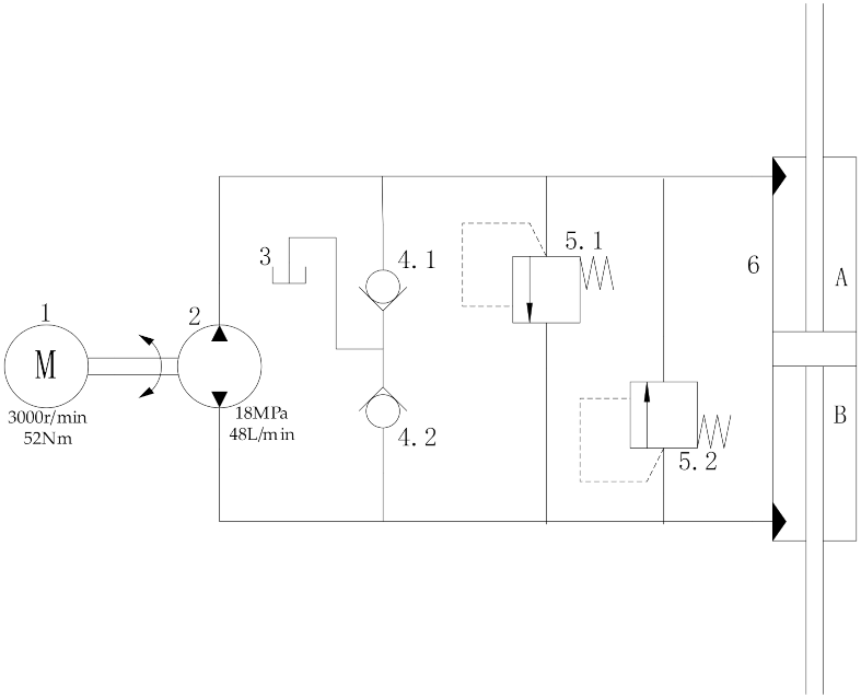
2.1. System Working Principle

Closed-loop electro-hydraulic servo pump control systems are divided into three categories: fixed-speed variable-displacement, variable-speed fixed-displacement, and variable-speed variable-displacement. The system scheme adopted in this study is variable-speed and fixed-displacement control. The principle of the hydraulic system is shown in Figure 1. By controlling the speed and torque of the servo motor, the flow and pressure of the two chambers of the hydraulic cylinder are regulated.

2.2. Mathematical Model Establishment

2.2.1. Mathematical Model of Servo Motor

The servo motor is the key control component of the electro-hydraulic servo pump control system, and its performance has a significant impact on position control. According to characteristics of the servo motor, such as nonlinearity, strong coupling, and time-varying parameters, a mathematical model was established.
In this system, in order to avoid demagnetization of the permanent magnet in the servo motor, the vector control method of I q = 0 is adopted, and the current of the q-axis is used to generate the electromagnetic torque of the system. The electromagnetic torque equation of the system is as follows:
T e = 3 2 p n ψ f i q
where T e is the electromagnetic torque of the servo motor, p n represents the pole pairs of the servo motor, ψ f is the flux linkage of the permanent magnet, and i q is the q-axis component of stator current.
The motion equation of the motor is as follows:
T e T L = J L d ω m d t + D ω m
where T L is the load torque of the servo motor, J L is the equivalent moment of inertia of the rotor shaft, ω m is the mechanical angular speed of the servo motor, and D is the rotational resistance coefficient.
The q-axis voltage equation of the equivalent armature circuit of the servo motor is as follows:
U q = L q d i q d t + R s i q + K e ω e
where U q is the q-axis component of stator voltage, R s is the stator electrical resistance, K e is the back electrodynamic force coefficient, and ω e is the rotor angular speed of the servo motor.
The control transfer function of the angular speed of the servo motor can be obtained by the Laplace transformation of Equations (1)–(3) as follows:
ω m = 3 2 p n ψ f U q K e ω e J L L q s 2 + J L R s + l q D s + D R s

2.2.2. Mathematical Model of Hydraulic Pump Cylinder Control

Considering the leakage and friction of the hydraulic pump, the mathematical model of the quantitative pump is as follows:
Q p = D p ω p C p p L
where Q p is the output flow of the quantitative pump, D p is the rated displacement of the quantitative pump, ω p is the angular velocity of the quantitative pump, C p is the leakage coefficient of the quantitative pump, and p L is the pressure of the load.
The flow continuity equation of the hydraulic cylinder is as follows:
Q L = A p d x p d t + C t c p L + V t 4 β e d p L d t
where Q L is the flow of the hydraulic cylinder, A p is the working area of the hydraulic cylinder, β e is the effective elastic bulk modulus, C t c is the total leakage coefficient of the hydraulic cylinder, V t is the total compressed volume, and x p is the displacement of the hydraulic cylinder.
The force balance equation of the hydraulic cylinder is as follows:
A p p L = m t d 2 x p d t 2 + B p d x p d t + K x p + F L
where m t is the mass of the load transferred to the piston, B p is the total viscous damping coefficient, K is the stiffness coefficient of the load, and F L is the external load force acting on the piston.
The position control transfer function of the hydraulic system can be obtained by the Laplace transformation of Equations (4)–(6) as follows:
x p = A p D p ω p F L C p + C t c + V t 4 β e s m t V t 4 β e s 3 + m t C p + C t c + B p V t 4 β e s 2 + C p + C t c B p + K V t 4 β e + A p 2 s + K C p + C t c
From Equations (4) and (8), the position control transfer function of the electro-hydraulic servo pump control system can be obtained as follows:
x p = A p D p 3 2 p n ψ f U q K e ω e J L L q s 2 + J L R s + L q D s + D R s F L C p + C t c + V t 4 β e s m t V t 4 β e s 3 + m t C p + C t c + B p V t 4 β e s 2 + C p + C t c B p + K V t 4 β e + A p 2 s + K C p + C t c
The establishment of the mathematical model of the position control of the electro-hydraulic servo pump control system lays a foundation for the implementation of the control strategy.

3. Load Disturbance Compensation Control Method

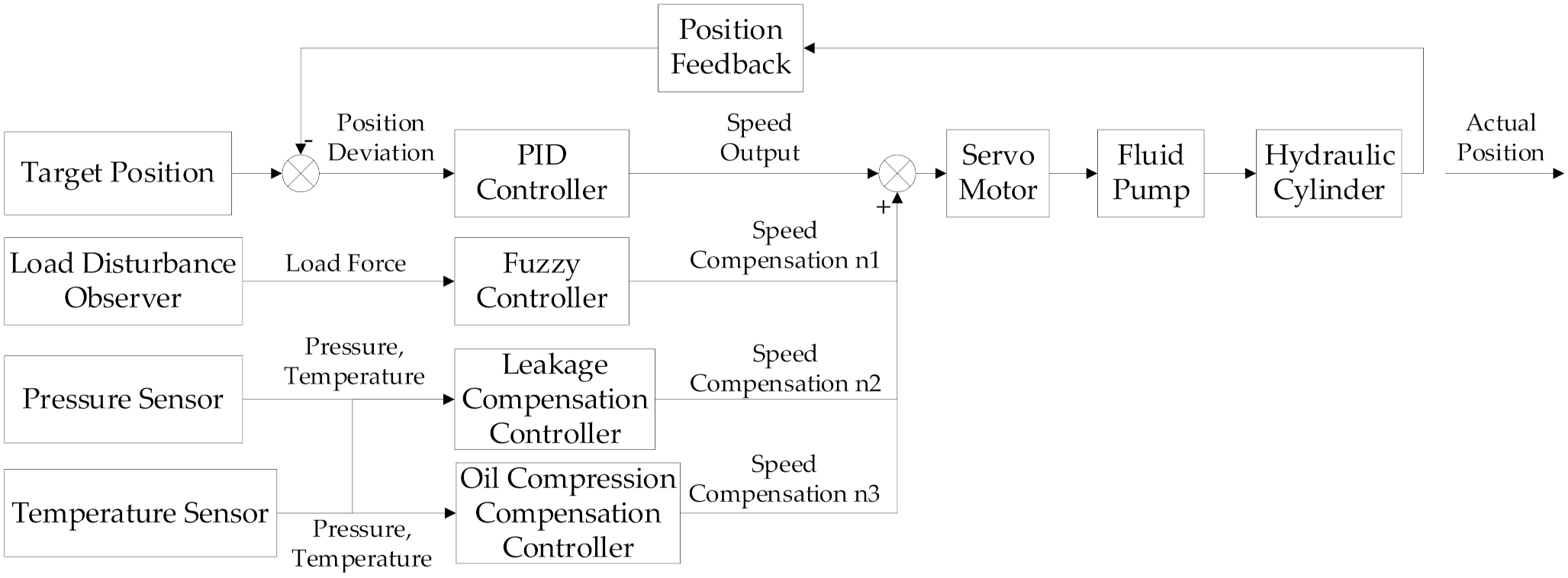
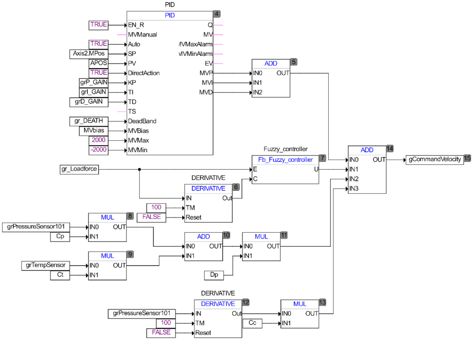
3.1. Control Strategy of System

According to the two-channel principle of absolute invariance [18], the control system consists of two parts. One part moves according to the given law, and this part adopts classical PID control. The other part is designed to counteract the disturbance caused by an external load force. In this part, the factors of oil compression and system leakage are considered, and fuzzy control theory is used to compensate for the load disturbance. The principle of the control system is shown in Figure 2.
In Figure 2, the position deviation of the hydraulic cylinder is processed by the PID controller then the basic speed is input into the servo motor. The load disturbance of the system is observed by the observer and then enters the fuzzy controller. The fuzzy controller inputs the compensation speed n1 to the servo motor. The pressure sensor signal and temperature sensor signal are fed back to the leakage compensation controller and the oil compression compensation controller. After being processed by the controller, the compensation speeds n2 and n3 are input into the servo motor, and the servo motor drives the quantitative pump to rotate and drive the hydraulic cylinder to move.

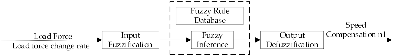
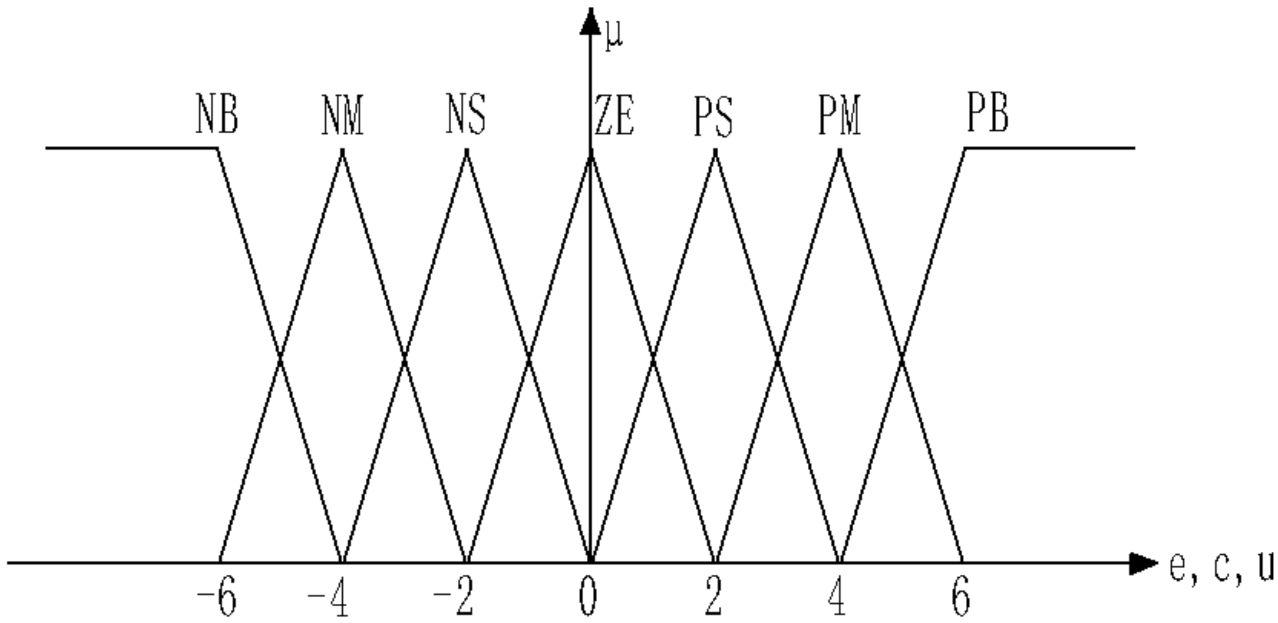
3.2. Fuzzy Compensation Control Algorithm

The load force of the system can be observed in real time through the working pressure of the system and the displacement of the hydraulic cylinder. The specific mathematical model is shown in Equation (10)
F L = A p p L m t d 2 x p d t 2 B p d x p d t K x p
The design of the fuzzy compensation controller includes three main parts, as shown in Figure 3. Firstly, the input/output variables of the load force and load force change rate are fuzzified, and the exact quantity is transformed into a fuzzy subset in a certain domain. Then, the fuzzy variables are compared with a fuzzy rule database for fuzzy reasoning. Finally, the output is defuzzified to obtain the accurate value of speed compensation.
A two-dimensional fuzzy controller was constructed for the electro-hydraulic servo pump control system. The fuzzy controller takes the load disturbance force (E) and the change rate of the load disturbance force (C) as input variables and the motor compensation speed (U) as an output variable. According to the fuzzy control rules, the domain is set to [−6, +6], and the triangular form is selected for the input and output fuzzy membership rules.
According to the requirements of high precision and rapidity of position control of electro-hydraulic servo pump control systems, seven values were selected as input and output language variables: negative large (NB), negative medium (NM), negative small (NS), zero (ZE), positive small (PS), positive medium (PM), and positive large (PB).
Membership function is the application basis of fuzzy control, mainly including triangle type membership function, Gaussian membership function, bell membership function, ladder membership function, and S-type membership function. The function of the membership function is to convert the output fuzzy quantity into an accurate quantity. When the slope of membership function is small, the controller can get higher steady-state accuracy; when the slope of membership function is large, the response speed of the system becomes faster. The input (E, C) and output (U) of the controller are all trigonometric membership functions which are widely used and easy to operate. The membership function of the fuzzy compensation control is shown in Figure 4.
Fuzzy control rules for the load disturbance force were established in accordance with relevant theories, as shown in Table 1.
After fuzzy reasoning, it is necessary to defuzzify the output. As shown in Equation (11), by using the weighted average method, each fuzzy variable x i in the fuzzy set is multiplied by the corresponding membership degree μ i and divided by the sum of membership degrees. After multiplying the obtained value by the scale factor, the value of motor compensation speed can be obtained so as to accurately regulate the position control of the electro-hydraulic servo pump control system.
x 0 = i = 0 n x i μ i i = 0 n μ i

3.3. System Leakage Compensation Control

In the electro-hydraulic servo pump control system, there is some leakage between the quantitative pump and the hydraulic cylinder, especially under a heavy load, which seriously affects the position control accuracy of the system. This paper proposes a system leakage compensation controller based on the real-time pressure and oil temperature of the system so as to realize high-precision position control.
The flow balance equation of system leakage is as follows:
D p n 2 = C t c + C p p L + C T T
where C T is the leakage coefficient of system temperature, and T is the operating temperature of oil in the system.
According to Equation (10), the leakage compensation control of the system is mathematically modeled as follows:
n 2 = C t c + C p p L + C T T D p

3.4. Oil Compression Compensation Control

In the electro-hydraulic servo pump control system, when the load pressure is rapidly adjusted, the volume change of the oil in the system will also affect the position control accuracy of the system due to the compressibility of the oil. In this paper, an oil compression compensation controller is proposed to compensate for the position control accuracy.
When the hydraulic cylinder pressure is rapidly adjusted, the system flow change equation is as follows:
D p n 3 = V t p ˙ L β e
According to Equation (13), the mathematical model of oil compression compensation control is as follows:
n 3 = V t p ˙ L β e D p
In sum, using the compensation control method, the output command for the speed compensation of the electro-hydraulic servo pump control system is as follows:
n = n 1 + n 2 + n 3 = n 1 + C t c + C p p L + C T T D p + V t p ˙ L β e D p
In order to verify the effectiveness of the control strategy, the control accuracy of the control strategy will be verified by experiments.

4. Experimental Analysis

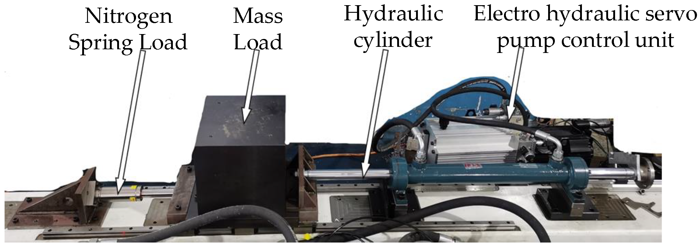
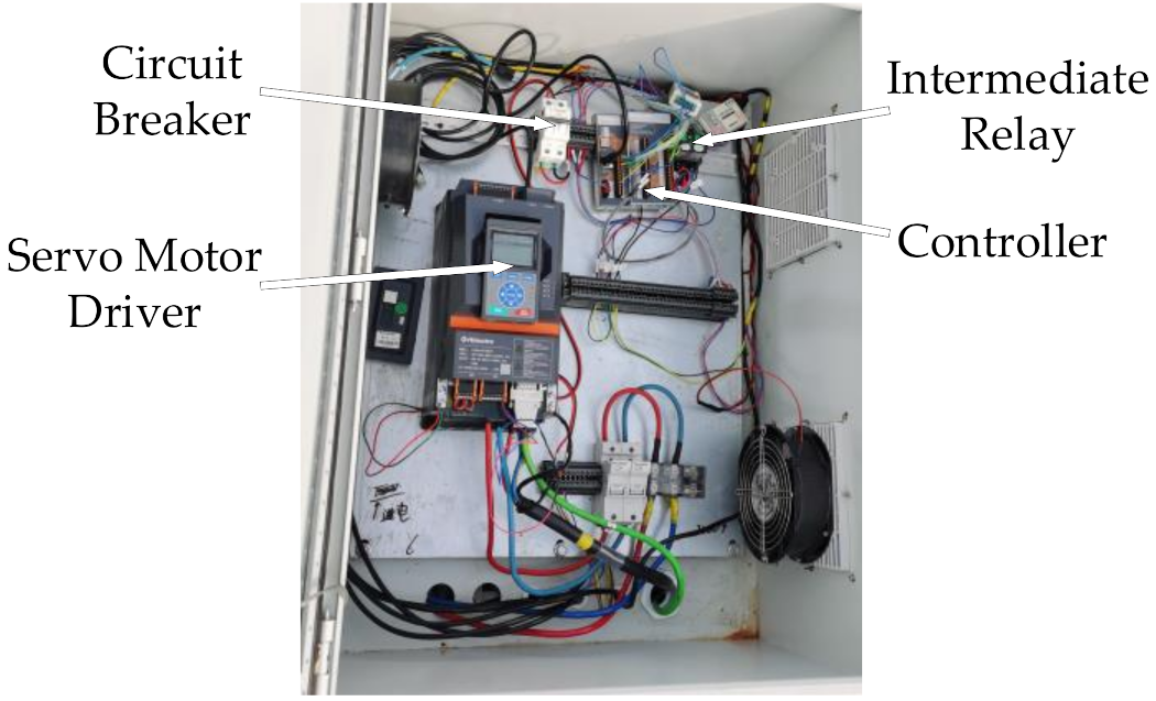
4.1. Experimental Platform

The experimental platform used to test the electro-hydraulic servo closed-pump control is composed of a hydraulic part and an electrical part. As shown in Figure 5, the hydraulic part includes the electro-hydraulic servo pump control unit, symmetrical hydraulic cylinder, nitrogen spring load, and spring load. The inertial load is used as the load force of the system, and the nitrogen spring load is used as the load disturbance force of the system. The load disturbance force of the system is adjusted by changing the compression of the spring. The electrical part is composed of the circuit breaker, servo motor driver, controller, and intermediate relay, as shown in Figure 6. The electro-hydraulic servo pump control unit integrates the power components and control components, which have such advantages as high power density and convenient layout. The system controls the speed and torque output by the servo motor through the driver and then controls the pressure and flow in the system so as to accurately control the output and position of the hydraulic cylinder. The main parameters of the experimental platform are shown in Table 2
In the electro-hydraulic servo pump control system, the system state is fed back to the controller by the pressure sensor and displacement sensor. The speed compensation values of the load disturbance obtained by the fuzzy control algorithm considering system leakage and oil compression are output to the servo motor through the controller so as to improve the control performance of the system.
The software part of the experimental platform is shown in Figure 7, which is mainly composed of PID control module, fuzzy compensation module, oil leakage compensation module, and oil compression compensation module. The speed of these four outputs constitutes the total speed of the motor output. The control test only uses the traditional PID control module to output motor speed. The program is downloaded to the controller through EtherCAT communication to realize the logic processing and operation of the system. The software used in the experiment is AutoThink software matched with HollySys motion controller, which is developed based on IEC61131-3 standard.

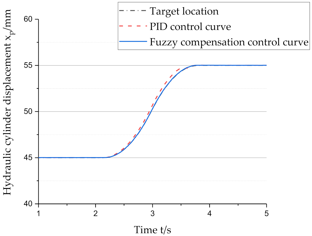
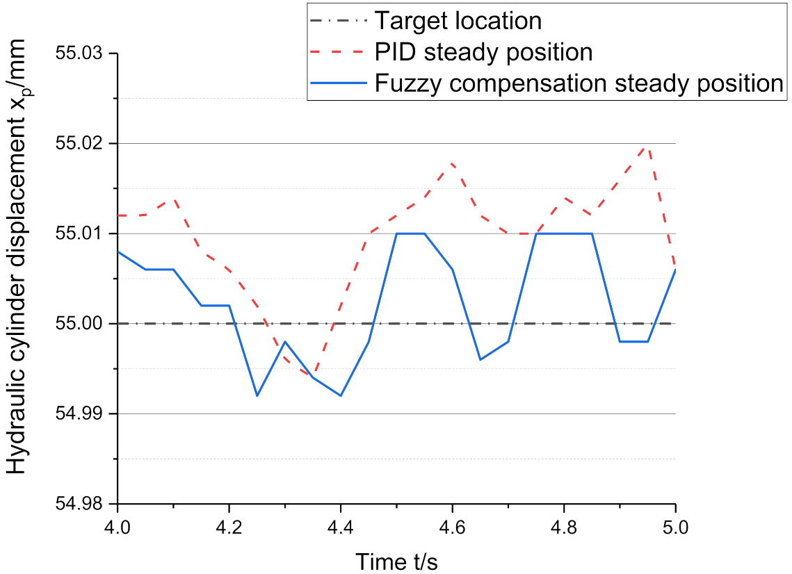
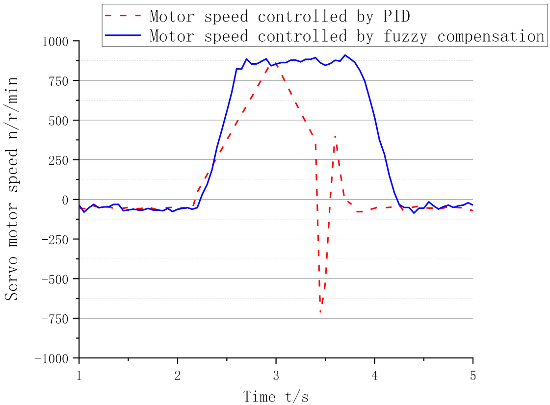
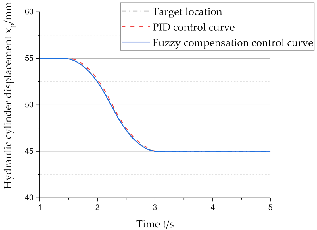
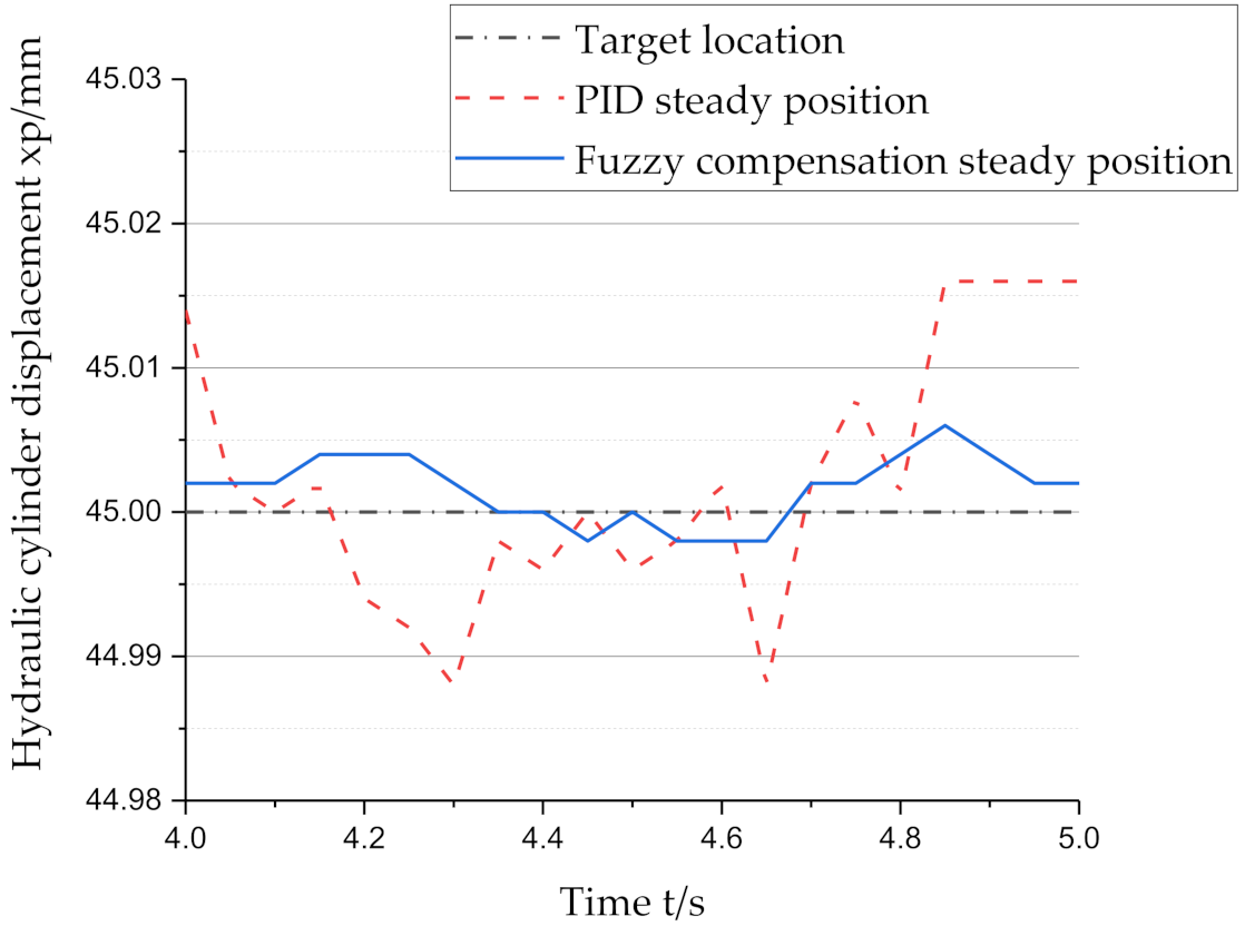
4.2. Analysis of Experimental Results

When the hydraulic cylinder extends, the nitrogen spring provides a certain external load interference force to increase the displacement from 45 mm to 55 mm and obtain the response curve between the position and local position of the hydraulic cylinder and the speed of the servo motor, as shown in Figure 8, Figure 9 and Figure 10.
As observed in the response curves for PID control and fuzzy compensation control, when the extension displacement signal is transmitted and fuzzy compensation control is applied, the speed of the servo motor rises rapidly to about 900 r/min and reaches a stable state. The speed fluctuation is small, and there are no sudden changes. The position tracking accuracy is controlled within ±0.01 mm, the control effect is good, and the dynamic performance of the system is improved. In PID control, the response speed of the servo motor is slow, the disturbance force fluctuates significantly, and the position tracking accuracy of the system is low.
When the hydraulic cylinder retracts, the nitrogen spring provides a certain external load interference force and moves the position from 55 mm to 45 mm. The response curves between the position and local position of the hydraulic cylinder and the speed of the servo motor are shown in Figure 11, Figure 12 and Figure 13.
The response curve indicates that when the retraction displacement signal is transmitted, the speed of the servo motor quickly rises to about −1000 r/min and reaches a stable state. There are no sudden changes in the speed of the servo motor, and the position tracking accuracy of the system is controlled within ±0.005 mm under the overload of the nitrogen spring. However, the response speed of the servo motor is slow under PID control. When the disturbance force appears, it fluctuates significantly, and the position tracking accuracy of the system is low.
Considering the oil leakage and compression of the system, the steady-state accuracy of the adaptive control strategy improved by the fuzzy control method is superior to traditional PID control and the electro-hydraulic servo pump control system mentioned in references [9,10]. In the process of extending and retracting the hydraulic cylinder, the position control accuracy of the system is different, which may be related to the pipeline layout of the system, and the leakage coefficient of the two cavities of the hydraulic cylinder is different, which is a problem that needs to be further studied. In this experiment, the load interference force used is provided by the nitrogen spring. Although the load force provided by the nitrogen spring changes with the displacement of the hydraulic cylinder, it cannot accurately simulate the random and irregular load interference force received by the system during normal operation. In the follow-up research process, the hydraulic cylinder and load can be made into the form of opposite cylinder jacking. The hydraulic cylinder at the position control end adopts fuzzy compensation control algorithm for position control, while the hydraulic cylinder at the load end adopts force closed-loop control to realize different forms of load by changing the force input signal at the load end.

5. Conclusions

In this paper, a mathematical model for the position control of the electro-hydraulic servo pump control system is established. According to the system leakage, oil compression, and other factors, in the event of a load disturbance, the output speed of the servo motor is compensated and controlled based on fuzzy control theory. In the experiment, the response characteristics of the two-way motion of the hydraulic cylinder were analyzed using the classical PID algorithm or fuzzy compensation control algorithm. The experimental results show that the position control accuracy is ±0.01 mm and ±0.005 mm with the fuzzy compensation control algorithm under overload conditions, which effectively improves the anti-disturbance ability of the system. The algorithm provides an effective method for the high-precision control of the system under the condition of external load fluctuations. In the future, in order to make the control method more coherent, we will consider establishing a leakage fuzzy compensation controller, oil compression fuzzy compensation controller, and fuzzy PID controller based on load disturbance fuzzy compensation control to improve the position control accuracy of the system.

Author Contributions

Conceptualization, Y.S.; data curation, Z.H.; formal analysis, C.A.; funding acquisition, Z.H.; methodology, Y.S.; supervision, C.A.; writing—original draft, Y.S.; writing—review and editing, Y.S. All authors have read and agreed to the published version of the manuscript.

Funding

This research was Sponsored by Shanghai Rising-Star Program (No. 19QB1406800), Shanghai Port Mechanical Engineering Technology Research Center Project (No. 20DZ2281300), National Key Research and Development Program (No. 2017YFC0805703).

Institutional Review Board Statement

Not applicable.

Informed Consent Statement

Not applicable.

Data Availability Statement

Not applicable.

Conflicts of Interest

The authors declare no conflict of interest.

References

  1. Guo, Q.; Li, X.; Jiang, D. Full-state error constraints based dynamic surface control of electro-hydraulic system. IEEE Access 2018, 6, 53092–53101. [Google Scholar] [CrossRef]
  2. Mahato, A.C.; Ghoshal, S.K. Energy-saving strategies on power hydraulic system: An overview. Proc. Inst. Mech. Eng. Part I J. Syst. Control Eng. 2021, 235, 147–169. [Google Scholar] [CrossRef]
  3. Shang, Y.; Li, X.; Wu, S.; Pan, Q.; Huang, L.; Qian, H.; Jiao, Z. A novel electro hydrostatic actuator system with energy recovery module for more electric aircraft. IEEE Trans. Ind. Electron. 2019, 67, 2991–2999. [Google Scholar] [CrossRef]
  4. Chen, W.; Wang, X.; Zhang, F.; Liu, H.; Lin, Y. Review of the application of hydraulic technology in wind turbine. Wind. Energy 2020, 23, 1495–1522. [Google Scholar] [CrossRef]
  5. Ma, K.; Sun, D.; Sun, G.; Kan, Y.; Shi, J. Design and efficiency analysis of wet dual clutch transmission decentralised pump-controlled hydraulic system. Mech. Mach. Theory 2020, 154, 104003. [Google Scholar] [CrossRef]
  6. Liu, H.; Zhang, X.; Quan, L.; Zhang, H. Research on energy consumption of injection molding machine driven by five different types of electro-hydraulic power units. J. Clean. Prod. 2020, 242, 118355. [Google Scholar] [CrossRef]
  7. Suzuki, R.; Komagata, M.; Ko, T.; Murotani, K.; Kaminaga, H.; Tatano, M.; Yamamoto, K.; Nakamura, Y. Development of 3-DOF wrist mechanism for electro-hydrostatically driven robot arm. Adv. Robot. 2020, 34, 958–973. [Google Scholar] [CrossRef]
  8. Ji, X.; Wang, C.; Zhang, Z.; Chen, S.; Guo, X. Nonlinear adaptive position control of hydraulic servo system based on sliding mode back-stepping design method. Proc. Inst. Mech. Eng. Part I J. Syst. Control. Eng. 2021, 235, 474–485. [Google Scholar] [CrossRef]
  9. Ren, G.; Esfandiari, M.; Song, J.; Sepehri, N. Position control of an electrohydrostatic actuator with tolerance to internal leakage. IEEE Trans. Control Syst. Technol. 2016, 24, 2224–2232. [Google Scholar] [CrossRef]
  10. Fu, Y.; Han, X.; Sepehri, N.; Zhou, G.; Fu, J.; Yu, L.; Yang, R. Design and performance analysis of position-based impedance control for an electrohydrostatic actuation system. Chin. J. Aeronaut. 2018, 31, 584–596. [Google Scholar] [CrossRef]
  11. Esfandiari, M.; Sepehri, N. Controller Design and Stability Analysis of Output Pressure Regulation in Electrohydrostatic Actuators. J. Dyn. Syst. Meas. Control 2019, 141, 041008. [Google Scholar] [CrossRef]
  12. Nguyen, M.T.; Dang, T.D.; Ahn, K.K. Application of electro-hydraulic actuator system to control continuously variable transmission in wind energy converter. Energies 2019, 12, 2499. [Google Scholar] [CrossRef] [Green Version]
  13. Lee, W.; Kim, M.J.; Chung, W.K. Asymptotically stable disturbance observer-based compliance control of electrohydrostatic actuators. IEEE/ASME Trans. Mechatron. 2020, 25, 195–206. [Google Scholar] [CrossRef]
  14. Suh, S.; Kim, W. Nonlinear position control using differential flatness concept with load torque observer for electro hydraulic actuators with sinusoidal load torque. Mathematics 2020, 8, 1484. [Google Scholar] [CrossRef]
  15. Van Nguyen, T.; Ha, C. Experimental study of sensor fault-tolerant control for an electro-hydraulic actuator based on a robust nonlinear observer. Energies 2019, 12, 4337. [Google Scholar] [CrossRef] [Green Version]
  16. Helian, B.; Chen, Z.; Yao, B. Precision Motion Control of a Servo Motor-Pump Direct Drive Electro-hydraulio System with a Nonlinear Pump Flow Mapping. IEEE Trans. Ind. Electron. 2019, 67, 8638–8648. [Google Scholar] [CrossRef]
  17. Song, B.; Lee, D.; Park, S.Y.; Baek, Y.S. Design and Performance of Nonlinear Control for an ElectroHydraulic Actuator Considering A Wearable Robot. Processes 2019, 7, 389. [Google Scholar] [CrossRef] [Green Version]
  18. Nguyen, A.T.; Taniguchi, T.; Eciolaza, L.; Campos, V.; Palhares, R.; Sugeno, M. Fuzzy control systems: Past, present and future. IEEE Comput. Intell. Mag. 2019, 14, 56–68. [Google Scholar] [CrossRef]
Figure 1. Hydraulic system diagram of electro-hydraulic servo pump control system: 1—servo motor; 2—quantitative pump; 3—hydraulic oil tank; 4—check valves; 5—relief valves; 6—hydraulic cylinder.
Electronics 11 01159 g001
Figure 2. System control schematic diagram.
Electronics 11 01159 g002
Figure 3. Fuzzy controller design steps.
Electronics 11 01159 g003
Figure 4. Triangle type membership function diagram. Since the load force, change rate of the load force, and the output speed of electro-hydraulic servo pump control system are accurate quantities, and the control parameters in the fuzzy controller are fuzzy quantities, the range of variables [a, b] needs to be transformed into the domain [−6, 6], and each interval corresponds to different fuzzy sets. In this system, the range of load force is below 12 KN, and the domain of load force input variable is [−6, 6], so the quantization factor of load force input is 0.001; the range of load force change rate is [−60, 60], and the domain of input variable of load force change rate is [−6, 6], so the quantization factor of input quantity of load force change rate is 0.1; the range of output speed is [−300, 300], and the domain of output speed variable is [−6, 6], so the scale factor of output speed variable is 50.
Electronics 11 01159 g004
Figure 5. Hydraulic part of experimental platform.
Electronics 11 01159 g005
Figure 6. Electrical part of experimental platform.
Electronics 11 01159 g006
Figure 7. Software part of experimental platform.
Electronics 11 01159 g007
Figure 8. Response curve of the extended position of the hydraulic cylinder.
Electronics 11 01159 g008
Figure 9. Local magnification curve of the extended position of the hydraulic cylinder.
Electronics 11 01159 g009
Figure 10. Speed response curve of the servo motor.
Electronics 11 01159 g010
Figure 11. Response curve of the retracted position of the hydraulic cylinder.
Electronics 11 01159 g011
Figure 12. Local magnification curve of the retracted position of the hydraulic cylinder.
Electronics 11 01159 g012
Figure 13. Speed response curve of the servo motor.
Electronics 11 01159 g013
Table 1. Fuzzy control rule statement table.
UE
NBNMNSZEPSPMPB
CNBPBPBPBPMPMPSZE
NMPBPBPBPSPSZENS
NSPBPBPMPSZENSNM
ZEPMPMPSZENSNMNB
PSPMPSZENSNMNBNB
PMPSZEPSNMNBNBNB
PBZEPSPMNBNBNBNB
Note: NB is negative large, NM is negative medium, NS is negative small, ZE is zero, PS is positive small, PM is positive medium, and PB is positive large, E is the load force, C is the load force change rate, U is the speed compensation.
Table 2. Main parameters of the experimental platform.
NameNumerical ValueUnit
Area of rod cavity of hydraulic cylinder0.0945dm2
Maximum working pressure18MPa
Displacement of hydraulic pump16mL/r
Rated torque of servo motor52Nm
Rated power of servo motor10.9Kw
Publisher’s Note: MDPI stays neutral with regard to jurisdictional claims in published maps and institutional affiliations.

