Article

Methods to Improve Dynamic System Response of Power Compensators Using Supercapacitors in Low-Voltage Ride-Through (LVRT) Conditions

1
Department of Electrical and Computer Engineering, Sungkyunkwan University, Suwon 16419, Korea
2
Department of Electrical and Electronic Engineering, Kunsan National University, Kunsan 54150, Korea
*
Author to whom correspondence should be addressed.
Electronics 2022, 11(7), 1144; https://doi.org/10.3390/electronics11071144
Submission received: 16 February 2022 / Revised: 24 March 2022 / Accepted: 31 March 2022 / Published: 5 April 2022
(This article belongs to the Section Power Electronics)

Abstract

:
In this paper, a power compensator using supercapacitors in parallel to protect grid-connected devices connected to the distributed power supply in the case of a low-voltage ride-through (LVRT) situation in designed, and a grid-connected device control method with improved responsiveness is proposed. In the LVRT situation, the distributed generation power may boost the DC_link voltage, increasing the risk of destroying grid-connected devices. To prevent this, the power compensator designed in this study absorbs active power in a fault situation and stores it in the supercapacitor to suppress the DC_link voltage rise and efficiently use the power. In addition, we propose methods to improve the response of the grid reactive power through the reactive power compensation of the power compensator in LVRT situation. To this end, the power angle (θPW) was extracted through the formula, and the reactive power command, to be compensated by the power compensator, and the reactive power command, compensated by the grid-connected devices, were calculated according to the active power value. In this way, the grid power controlled by the power compensation device and the grid-connected devices was controlled by the active/reactive power of the same power angle and analyzed mathematically. Active power control and static grid support were performed in the normal state where the reduction rate of the normal value of the grid voltage was around 10%. However, when the grid voltage dropped by 10% to 100%, the reactive power control was appropriately performed with dynamic grid support by increasing the voltage from 10% to 20% or more. We conducted a simulation of the new and renewable energy grid-connected devices using the OPAL-RT-based Hardware-in-the Loop Simulation (HILS) system to control the proposed active/reactive power.

1. Introduction

In recent decades, the demand for renewable energy has increased significantly due to the depletion of fossil fuels and the disadvantages associated with environmental pollution. Among the types of renewable energy sources, wind power and solar power are the most promising and are developing rapidly due to developments in power electronics technology. Photovoltaic power generation produces electricity by converting light energy from the sun by employing solar cells that generate electricity via the photoelectric effect when it receives sunlight. Wind power generation converts wind power into rotational power and supplies the generated power to the power system or consumers. Wind power generation and photovoltaic power technologies are spotlighted as the future energy industry as they can generate electricity anywhere there is wind and sunlight, are easy to install, and have low prices [1,2,3].
In the meantime, relatively stable system operation is possible in the form of a unidirectional current that supplies electricity to each consumer through long-distance transport centered on large-scale power plants, which in turn are centered on nuclear and thermal power plants. On the other hand, as the demand for new and renewable energy increases, it is changing to a bidirectional current form due to distributed generation using wind power and photovoltaic power. As power generation facilities with uncertainties and output variability, such as solar and wind power, are connected to the power system, various challenges occur in system operation. One of these problems is the maintenance of grid coordination regulations, such as maintaining constant frequency and voltage due to frequent supply demand imbalances in the power system caused by the increased demand for distributed power generation, and grid connection regulations, such as strengthening power system reliability standards [4,5].
In the early days, while distributed power generation in the power system was insignificant, no significant issues occurred in the event of a grid accident, such as a voltage drop. When a fault occurred in the grid system, wind and photovoltaic power generators were able to suddenly disconnect from the grid system and reconnect when the grid was restored. However, in the recent power system, when distributed power generation increases, instantaneous separation from the grid seriously affects the safety of the whole electric power system. Many control methods have been studied to solve this problem, such as the On Load Tap Change (OLTC) of substation peripheral voltage, the Step Voltage Regulator (SVR) installed in the middle of distribution lines, and the capacitor bank at the output. However, similarly, due to the intermittent renewable energy, it is insufficient to quickly control voltage fluctuations or increase response quality while supplying power to the load, increasing system instability. In order to solve this problem, methods for improving system stability by applying inverters of a distributed generation are currently being investigated [6,7,8].
First, dynamic brake resistors (DBRs) are applied to wind power generation among distributed generation. The mechanical torque input through the blade pitch control is converted into electrical energy through the PMSG and the generator-side converter, and the converted electrical energy is supplied to the system through the system-side converter. This is a method of suppressing the increased voltage through an external resistor if the DC_link voltage rises due to more than a specific voltage when connected to a wind power generator. Most distributed power sources are applicable to grid interconnects and have the advantage of being relatively simple to control and configure, but require space to install external resistors, and the larger the capacity, the higher the required resistance. It has the disadvantage of increasing the required space [9,10].
Second, the de-loading droop control reduces the distributed generation power by controlling the gain value of the generator-side converter when the DC_link voltage of the High-Voltage Direct Current (HVDC) system rises above a specific voltage or a specific frequency. This method does not require external hardware and has the advantage of controlling even if there is a problem in the system. However, the speed of the turbine increases because the limited electrical output of the wind turbine is accumulated as the kinetic energy of the wind turbine. Additionally, since it takes time for the integral term of the proportional–integral controller, which is a DC-linked controller, to return to the control area, there is the disadvantage of taking a considerable time to recover after an accident [11].
Third, as an inverter power compensation control method, it is a method of compensating the generated power of a power conversion device for distributed power control according to the LVRT situation. When calculating the q-axis current of the generator-side converter, the amount of power generation is limited by multiplying the required generation command value by the reduction amount of the grid voltage. This control method has superior control performance compared to de-loading droop control and DBR control, and does not require an external device. However, this method has a relatively complex algorithm compared to other control algorithms, and in the case of an unbalance accident, such as a short circuit, the current magnitude of the grid-side converter is different, reducing the amount of power generation to smaller than the maximum power that can be introduced into the grid, resulting in inefficiency, and the power conversion device, power generation parameters, etc., are essential to determine [12].
In order to solve the grid connection problems caused by distributed generation, grid connection regulations have been enacted, and there is substantial interest in the stability of grid connection devices under LVRT conditions. New control methods are being updated to cooperate with system transients for continuous operation without destroying the grid connection of distributed generation [13].
It is operated according to each system situation in each country, but in this paper, we proceeded according to the German Grid Code regulation, which is the strictest regulation. To briefly explain the German Grid Code, dynamic/static grid system support according to the magnitude of the voltage is required, and the power control responsiveness is limited to 20 ms to meet the dynamic grid demand in the LVRT situation. As shown in control block diagram, the dq-axis inverter active/reactive power control through PLL method satisfies the control responsiveness standard of 20 ms. This responsiveness criterion requires faster current responsiveness as distributed power becomes more complex and distributed power increases [14,15,16,17].
In this paper, we designed a power compensator using supercapacitors in parallel to protect the grid-connected devices connected to the distributed power supply in the case of an LVRT situation, and proposed a grid-connected device control method with improved responsiveness. At this time, we applied supercapacitors used in application fields, such as power quality improvement, high current, and high output, on the application field side where a high output must be supplied in a short time. Supercapacitors are more expensive than lead-acid or lithium batteries but have a high charge/discharge rate [18,19,20,21]. Hence, when installed instead of batteries generally used in configuring the power compensator, supercapacitors can obtain higher output and significantly shorten the charging time as storage devices. We propose a power compensate device configuration and design control method to match the fast power control responsiveness, as well as the grid power compensate device protection control, and try to verify it using the OPAL-RT-based HILS system. A simulation experiment of an LVRT condition was conducted by forming a 0.5 pu drop at the grid voltage of 1 pu, and then the response improvement was verified.

2. Grid-Connected Devices under LVRT Conditions

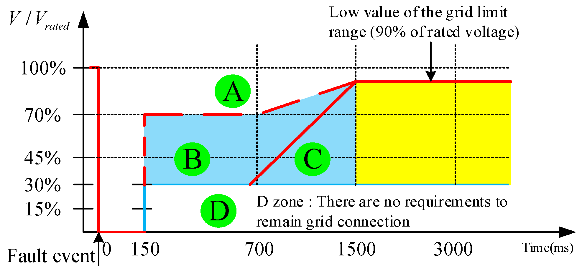
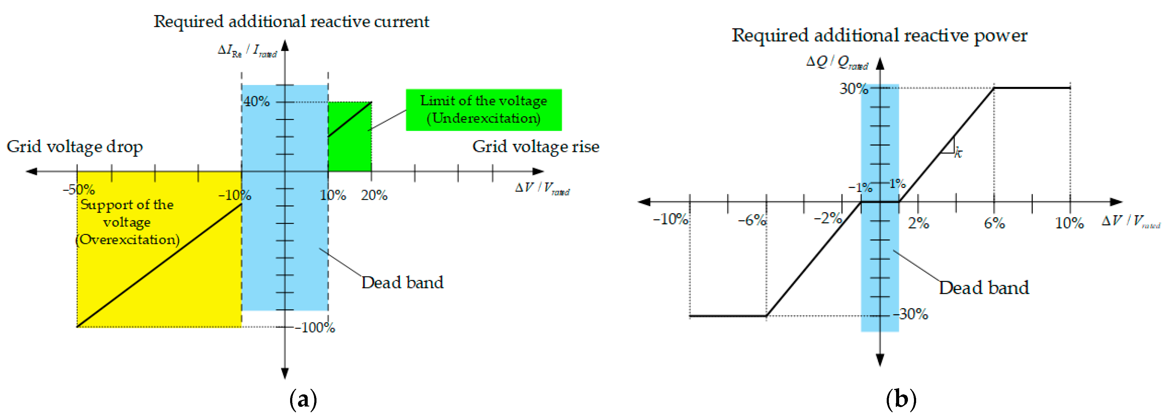
2.1. Grid Connection Standards of LVRT Conditions according to German Grid Code

German Grid Code regulations that the operation shown in Figure 1 needs to be per-formed in a low-voltage situation. According to the LVRT operating conditions defined in the Grid Code, it can be seen that the grid connection conditions of grid-connected devices are different according to the grid voltage and fault time. There is an obligation to maintain the connection between the system interconnection device and the system up to 150 ms based on the occurrence of an accident. In Zone A, all systems must always maintain grid connection with the system and operate normally. Zone B must perform normal operation like Zone A, and it operates so as not to separate from the system, or it can be separated at the moment of failure occurrence with the consent of the system operator, but must be reconnected within 2 s. This reconnection rule is defined as Short Time Interrupt (STI). Zone C is allowed to be separated from the grid regardless of the grid management system, but it must be reconnected within 2 s to supply active power at a rate of increase of 10% or more of the rated power per second. Finally, the D Zone does not define the specific contents regarding the Grid Code regulation.
Figure 2 shows the LVRT regulations in the Grid Code, which can be divided into dynamic grid support and static grid support. Additionally, reactive power should be supplied to the grid according to the dynamic grid support when the grid voltage is 10% or more and the static grid support when the grid voltage is less than 10%. For example, if the grid voltage is reduced by 50%, the required reactive current should be transmitted to the grid at 100% of the maximum current. The reactive current required for dynamic grid support should be supplied within 20 ms to stabilize the grid. If the voltage reduction rate is within 10% of the steady state standard, it is defined as a dead band, and the reactive current supply regulation according to the voltage reduction rate different from the dynamic system support is defined in the Grid Code. This is called static system support, and the regulation of reactive current supply according to voltage fluctuations is defined in consultation with the system management system according to the state of the grid. Static grid support is a method of supplying an appropriate reactive power when the grid voltage is within ±10% in a steady state. In general, it should be possible to change the reactive power setting value according to the user’s request in all operating conditions. Therefore, it is necessary to be able to supply a certain range of reactive power even under the supply condition of 100% active power, which means that the capacity of the grid interconnection device must be designed to be larger than before in the concept of apparent power.

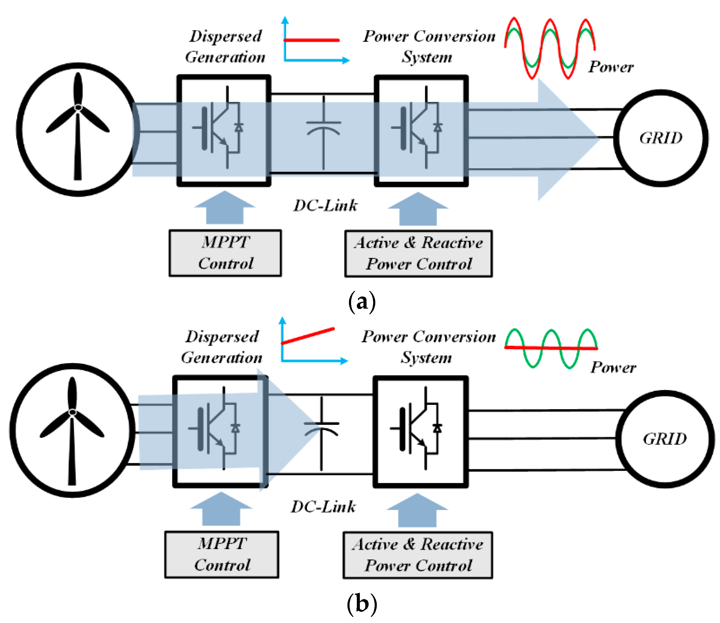
2.2. Grid-Connected Device Problems under LVRT Conditions

As shown in Figure 3a, when grid-connected devices are in a normal state, the DC_link voltage is stabilized because all the power generated by the distributed generation is transmitted to the grid. However, in the LVRT situation shown in Figure 3b, the grid voltage is lowered, so the power generated from the distributed power source is reduced. In this case, all the power generated by the distributed power source is not transmitted to the grid, and the remaining power causes the DC link voltage to rise. As a result, the voltage rises due to active power. If the user does not limit the output power of the distributed power source, the destruction of the grid-connected devices occurs due to the increase in the DC_link voltage.

3. Grid-Connected Devices with the Proposed Power Compensator

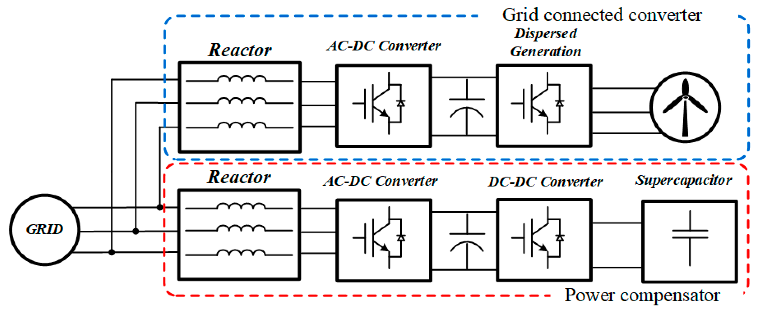
3.1. Grid-Connected Devices with Power Compensators

In an LVRT situation, the energy generated from the distributed generation is stored in the power compensator to stabilize the DC_link voltage of grid-connected devices. Figure 4 shows the power control method and configuration with a power compensator and grid-connected devices.
The voltage equation of the equivalent circuit of the 3-phase AC–DC converter in Figure 5 is as follows.
e a = L i d i a d t + V a ,     e b = L i d i b d t + V c ,     e c = L i d i c d t + V c
where e a , e b , e c : output voltages; i a , i b , i c : phase currents; and v a , v b , v c : control voltages. By converting the voltage equation of Equation (1) into a voltage equation of the two-phase stationary coordinate system, Equation (2) is obtained as follows:
v d s s = L d i s d s d t + e d s s ,     v q s s = L d i s q s d t + e q s s
Additionally, one can obtain Equation (3) by converting Equation (2) to a voltage equation of the two-phase rotating coordinate system.
v d e = L d i e d s d t ω L i d e + v d s e ,     v q e = L d i e q s d t + ω L i d e + v q s e
Figure 6 expresses the dq vector control, and the ia magnitude and direction can be controlled using Equation (3). When the grid voltage and phase are the same, AC→DC power is generated, and when the grid voltage and current are 180 degrees in phase, AC DC power is generated. In cases of other current phase operations, reactive power is generated. Substituting eed = 0, eeq = E into the synchronous coordinate system results in the following formula:
0 = L d i e d s d t ω L i d e + v d s e ,     E = L d i e q s d t + ω L i d e + v q s e
When controlling ied and ieq based on the eeq = E q-axis phase voltage, the phase of the current is controlled, so it is possible to control active and reactive power. In order to control the active and reactive power, the product of the voltage and current converted into a three-phase rotating coordinate system, the active power and reactive power of the system can be readily obtained through Equation (5):
p = 3 2 ( v q i q + v d i d ) ,     q = 3 2 ( v q i d v d i q )
The control block diagram of grid-connected devices of distributed generation is shown in Figure 7.
Grid-connected devices for power compensation are a standard configuration for LVRT support. The three-phase grid-connected devices and the controller can perform feedforward control for the SVPWM switch operation of the AC–DC converter using the sensed grid current value. A current controller that generates a voltage value that is a two-phase synchronous coordinate value by reflecting the current sensed value of the grid-connected device and the LVRT current reference (ir* dqs_GD) determines the voltage value. This is the two-phase synchronous coordinate value of a three-phase rectangular coordinate, which consists of an inverse coordinate value converter. The PLL method is used to estimate the grid phase from the sensed grid voltage value. Feedforward control is generally implemented using the SVPWM method, and a DC_link voltage value is sensed as a feedback parameter of the feedforward control. In order to improve the response of current control, a feedforward compensation method based on grid voltage and parameters is generally used. The feedforward compensation value may be composed of the magnitude of the grid voltage and the inductance voltage value. In feedforward control, each parameter derived from the sensed voltage value and current value converts a three-phase coordinate system to a two-phase stationary coordinate system and a two-phase stationary coordinate system to a synchronous coordinate system. The three-phase grid voltage value (Vac), a three-phase orthogonal coordinate value, is converted into a two-phase dq synchronization coordinate value (Vrdqs) through coordinate transformation. Additionally, the three-phase grid current value (iuvw), a three-phase rectangular coordinate value, is converted into a two-phase dq synchronization coordinate value (irdqs) using the current value coordinate. The source power calculation control block reflects the command value of the DC_link voltage to the current DC_link voltage and calculates the generated power supplied by the distributed generation power generation system in the low-voltage acceptance operation situation, excluding the power required inside the distributed power generation system, as shown in Figure 8. This calculates the current generated power value by multiplying the present voltage value (Vdc) and the present current value (Idc) of the DC-link. The difference between the DC_link current–voltage (Vdc) and the command voltage (V*dc) is calculated. Then, the generated power (Pgen) supplied to the grid in the LVRT condition is calculated by subtracting the offset power from the current generated power value through the voltage controller that calculates the offset power.
As a peculiarity, the generated power is not calculated based only on the DC_link voltage/current value sensed at the specific moment, but by also compensating for the expected change in the DC_link voltage. In this way, it is possible to consider the loss caused by the grid-connected device hardware and switching, which is difficult to calculate in practice, so that the power to be discharged to the grid or the power compensator in an LVRT condition can be calculated more accurately. Figure 9 shows the detailed block diagram of the power distributor.
This can be divided into a controller for limiting active power and a controller for controlling reactive power. The power distribution operation controller first calculates the difference in the apparent power product (S2rate) that the output power defined by the Grid Code can output in the grid-connected devices, as shown in Equation (6), and limits it through a limiter. Then, it is inversely squared to compare it with the active power value based on the Grid Code.
S G D 2 = P G D * + Q G D *
Equation (7) shows that the limited active power is compared with the generated power (Pgen) calculated in Figure 9. Based on the estimated value, the power compensator performs charging or discharging to distribute power within the grid-connected devices.
P L i m i t * > P g e n P L i m i t * P g e n                   P c o m p dis   charge P c o m p   charge  
The formula for extracting the power phase (θPW) from the active power value (P*GD) and reactive power value (Q*GD) according to the Grid Code is shown in (9).
P G D * = S G D * cos θ P W Q G D * = S G D * sin θ P W
θ P W = tan 1 Q G D * P G D *
tan θ P W = sin θ P W cos θ P W
Q * = P * tan θ P W Q c o m p * = P c o m p * tan θ P W
The reactive power command (Q*comp), compensated by the power compensator according to the value of the active power with the extracted power angle (θPW), and the reactive power command (Q), compensated by grid-connected devices, are calculated. In this way, the grid power controlled by the power compensator and grid-connected devices can be controlled with the active/reactive power of the same power angle.
As a result, the phases of grid voltage and current that change depending on the commands of i*q and i*d can be confirmed, as shown in Figure 10.
At this time, the current magnitude can be expressed as in Equation (12) below:
i a = i 2 q + i 2 d
When such a voltage/current phase difference is confirmed, active power appears due to the voltage and current phase difference. Furthermore, when the current is before the voltage, the true reactive power appears, and when the current lags behind the voltage, the lagging reactive power appears. Therefore, based on the phase difference in current and the active power of the grid, when the power of the grid-connected device sends active and reactive power to the grid, as in Equation (8), it is possible to control the charging and discharging of the power compensator. In this case, as shown in Figure 11, for example, when the active power generated by the grid connected device is less than the active power required by the grid, the grid is more effective than the active power generated by the grid connected device. If more power is required, the magnitude of the reactive power is shown in the figure below.

3.2. Designing a 3-Phase AC–DC Converter Reactor

The inductance of the input stage reactor plays the most critical role in the control performance of a three-phase AC–DC converter. As the inductance of the input stage reactor increases, the ripple of the current is removed. However, in general, if the inductance of the reactor is large, the size and price of the reactor increase, and the cost and volume of the power compensator also increase. Therefore, it is important to select a reactor with an optimal inductance, and it is necessary to prove it mathematically. The phase between the input voltage and the voltage across the inductor is 90 degrees. Therefore, it must be controlled to have the same phase as in Figure 11 to synchronize the phases of the input current and the input voltage. On the other hand, the maximum voltage modulated by the AC–DC converter of the power compensator is the same as in Equation (13), which means the maximum value of the voltage.
V a b max = V a c 2 3
If the control is performed smoothly and the maximum output value is the same as the input active power, the input current can be converted into an equation for each angle, and Equation (14) is expressed as follows:
V d c I d c = 3 e a b i a b cos θ                     = 3 e a b V a b ω L i sin α
where θ is the phase difference between the input voltage and the input current. In this way, if the minimum inductance according to the maximum controllable voltage fluctuation is selected, it can be obtained via the following equation:
L i 3 e a b V a b max sin ( cos 1 ( e a b V a b max ) ) ω V d c I d c

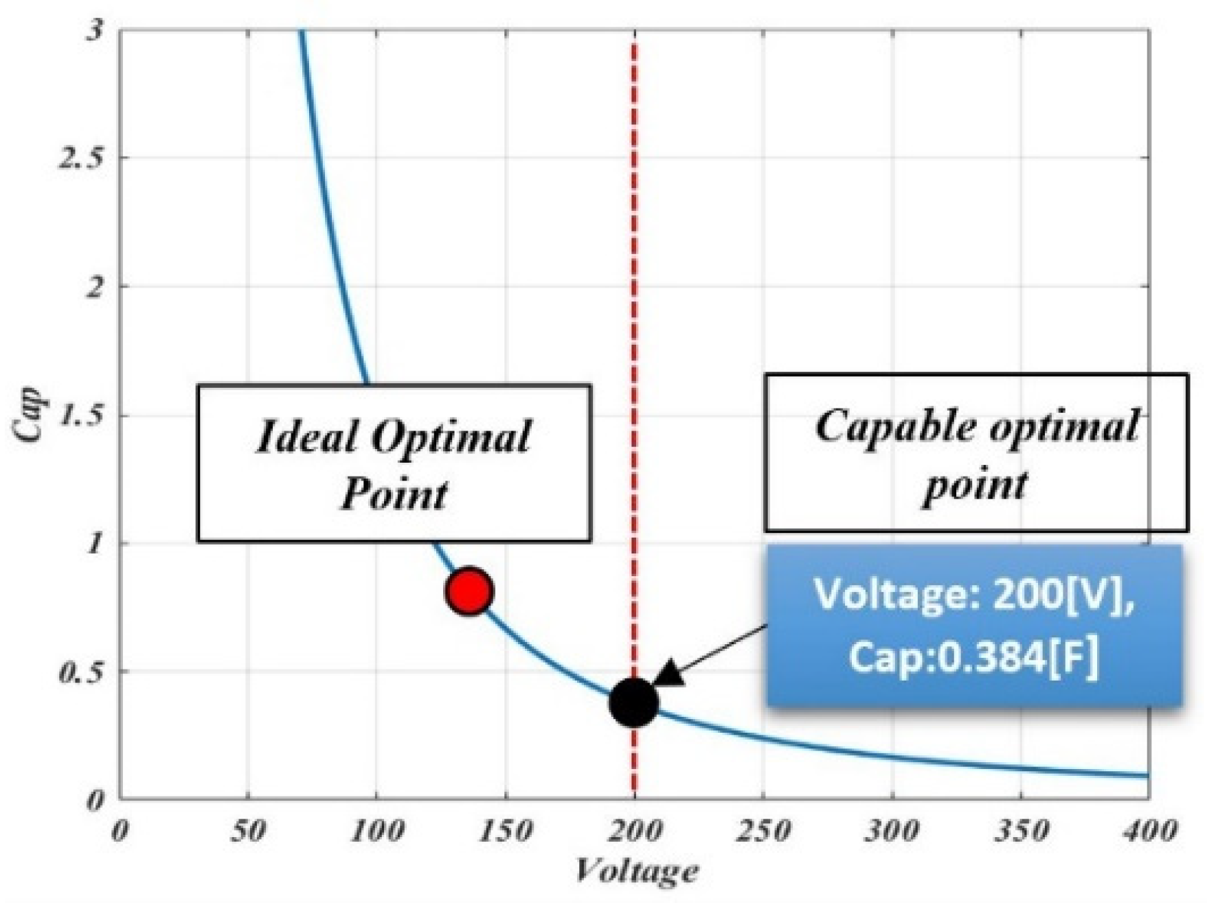
3.3. Supercapacitor Capacity Calculation and Design Method

It is necessary to calculate the supercapacitor capacity to control charging and discharging using the DC–DC converter of the power compensator. Under LVRT conditions, if the compensation time is 1.5 s, the designed grid-connected device’s rated output is 10 kW, and the DC_link voltage is 400 V; the voltage of the supercapacitor connected to the half-bridge type DC–DC converter should be doubled or less to improve efficiency. Therefore, the capacitance should be selected from the Ideal Optimal Point value, as shown in Figure 12, but if calculated according to the rated voltage, the value is 0.384 F. When the grid voltage falls below 50%, since the reactive current must be supplied in connection with the grid for at least 150 ms, the voltage of the supercapacitor rises, and the stability of the capacitor must be ensured within the maximum duration of 1.5 s.
In addition, the total capacitance of the supercapacitor can be expressed using the power compensation capacity.
P S = C V 2

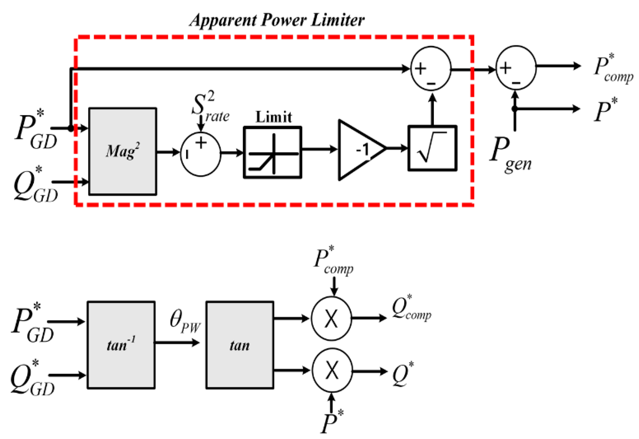
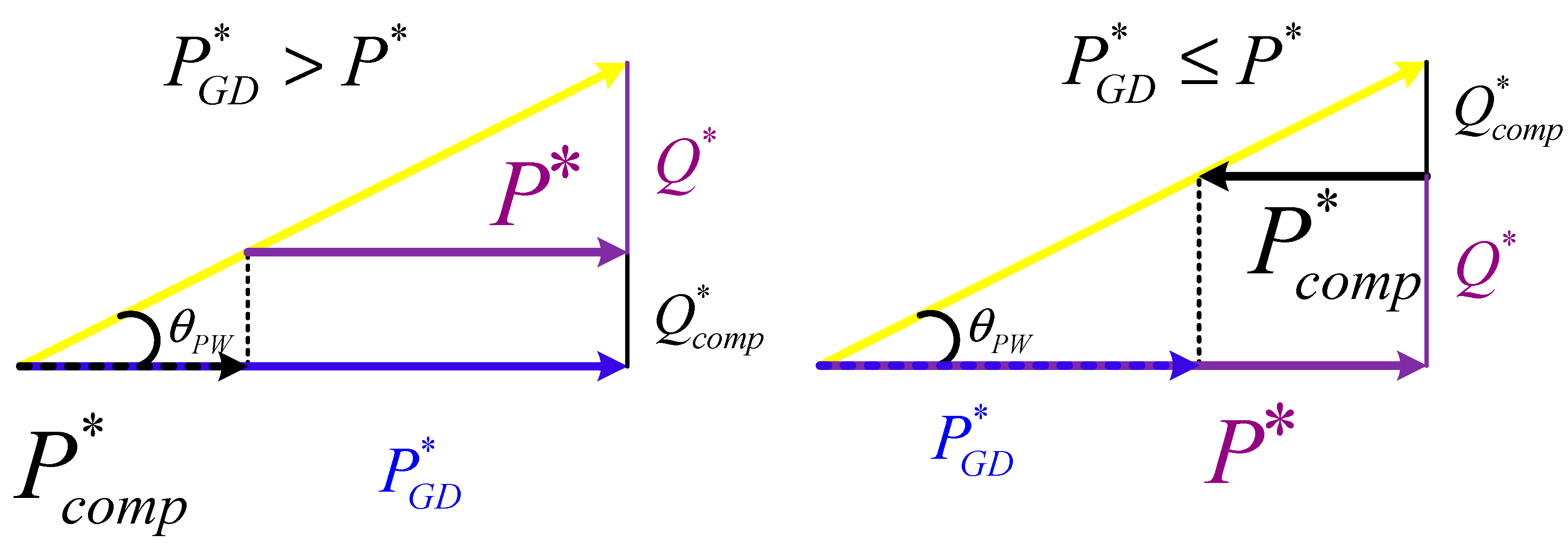
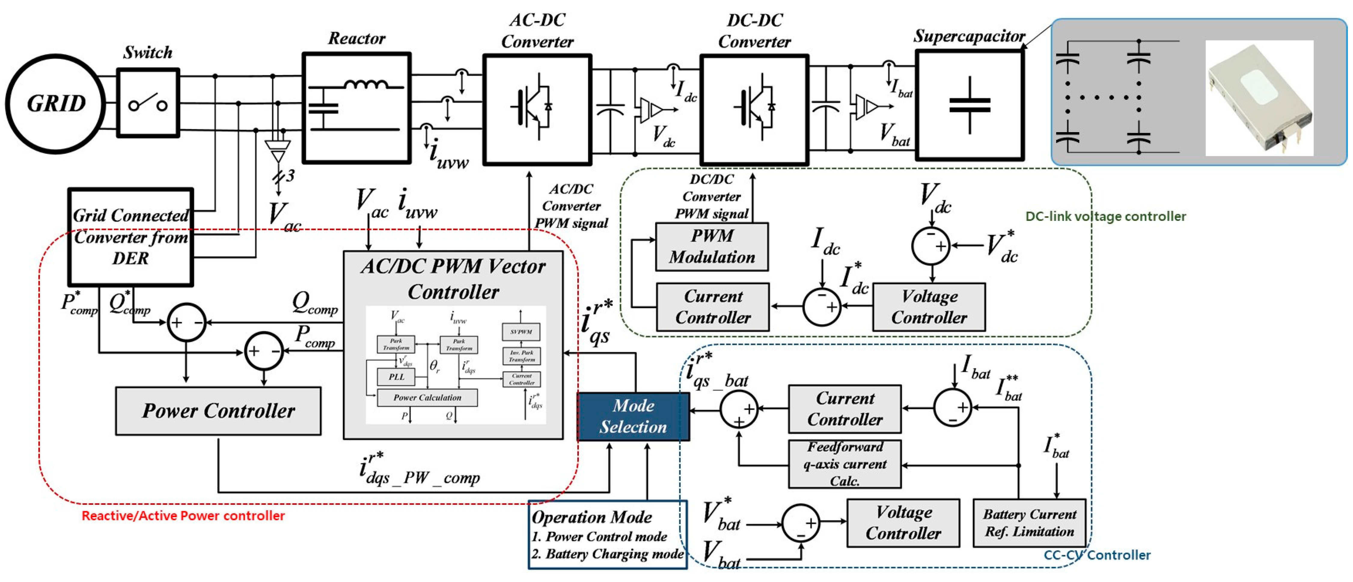
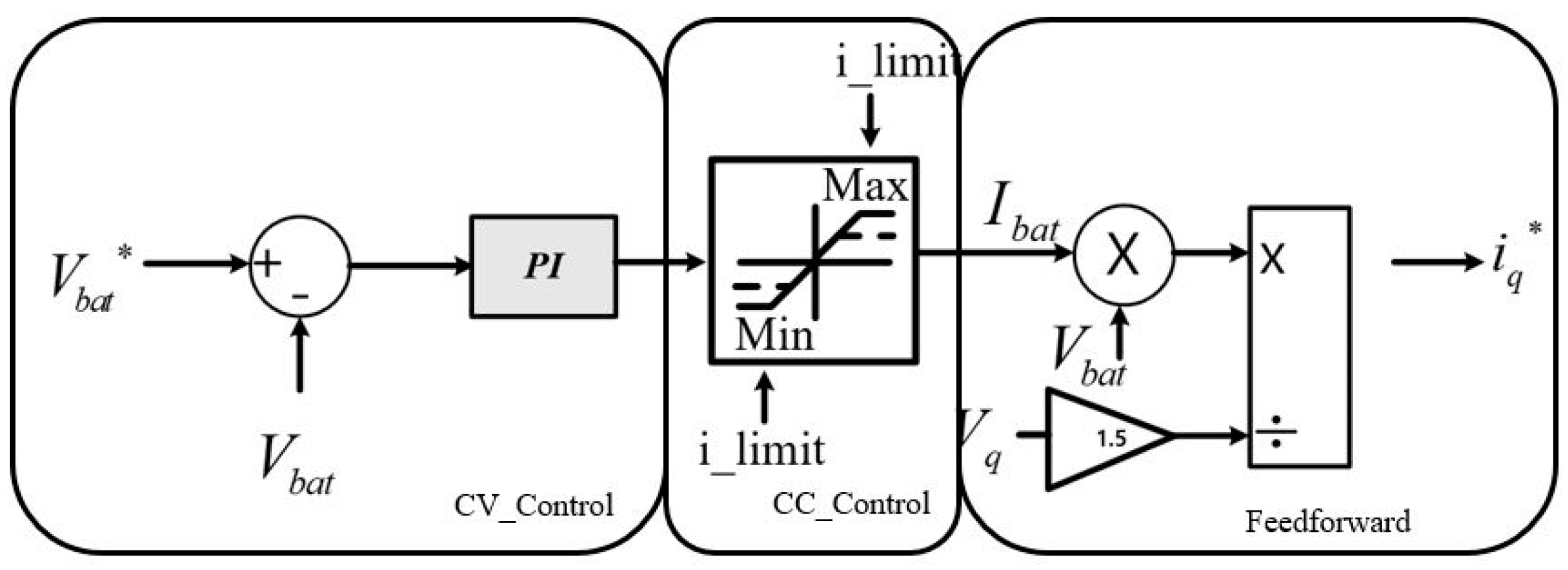
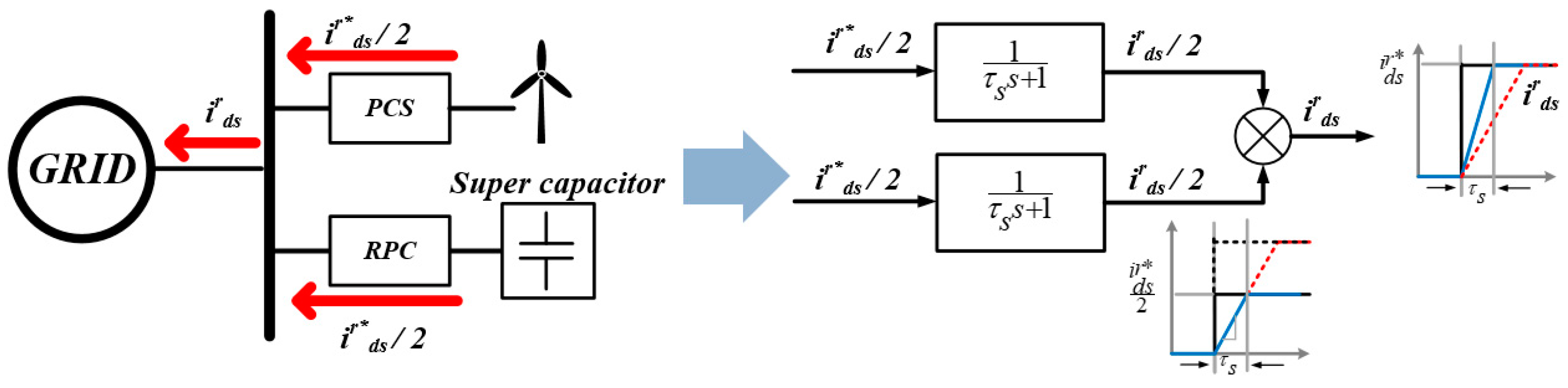
3.4. Power Compensation and Charging/Discharging Control Method of Power Compensators

As shown in the active power and reactive power control part of the control algorithm block diagram for a power compensator in Figure 13, it is designed to compensate for reactive power according to the state of the grid. For the normal component of the normal system voltage in the normal state where the reduction rate of the effective value is above or below 10%, the active power control and the static grid support described above are performed; the system voltage is −10% to −100% when the voltage is reduced, and 10~20% or more supports the dynamic system of voltage rise and supplies reactive power appropriately. To measure the 3-phase grid voltage and output the reactive power command, the normal grid voltage command is output as 0, but when the LVRT condition control mode is in progress, the active power command varies depending on the grid voltage level. The output reactive power command is limited using Equation (17) to be controlled within the apparent power range.
Referring to Figure 14, the Vbat voltage of the Constant Voltage (CV) control is compared with the V*bat command voltage, and the current command is generated to the same extent as the error.
At this time, to remove the error component altogether, the controller receives the input from the PI controller and outputs the DC component. As for the output current, Ibat is output within the current range specified through Constant Current (CC) control. At this time, I*c is output because current control is performed using dq conversion, and feedforward control is performed for load fluctuations. Therefore, the output i*c can compensate for the energy of the supercapacitor to the grid and, conversely, absorb the power of the grid to the supercapacitor.
P = 3 2 E i q s * = V D C l i n k I D C l i n k = V b a t I b a t i q s * = 2 V b a t 3 E I b a t
The load of the bidirectional DC–DC converter is a supercapacitor, and if the voltage and current desired by the user are small, CC and CV control are applied to control the voltage and current. However, if this control is neglected, the internal resistance of the supercapacitor is low, and the current rapidly increases, which may damage the power compensator. Additionally, if the withstand voltage is over 400 V, there is a risk that the supercapacitor may be damaged. Based on this fact, it is controlled through constant current (CC) and constant voltage (CV).

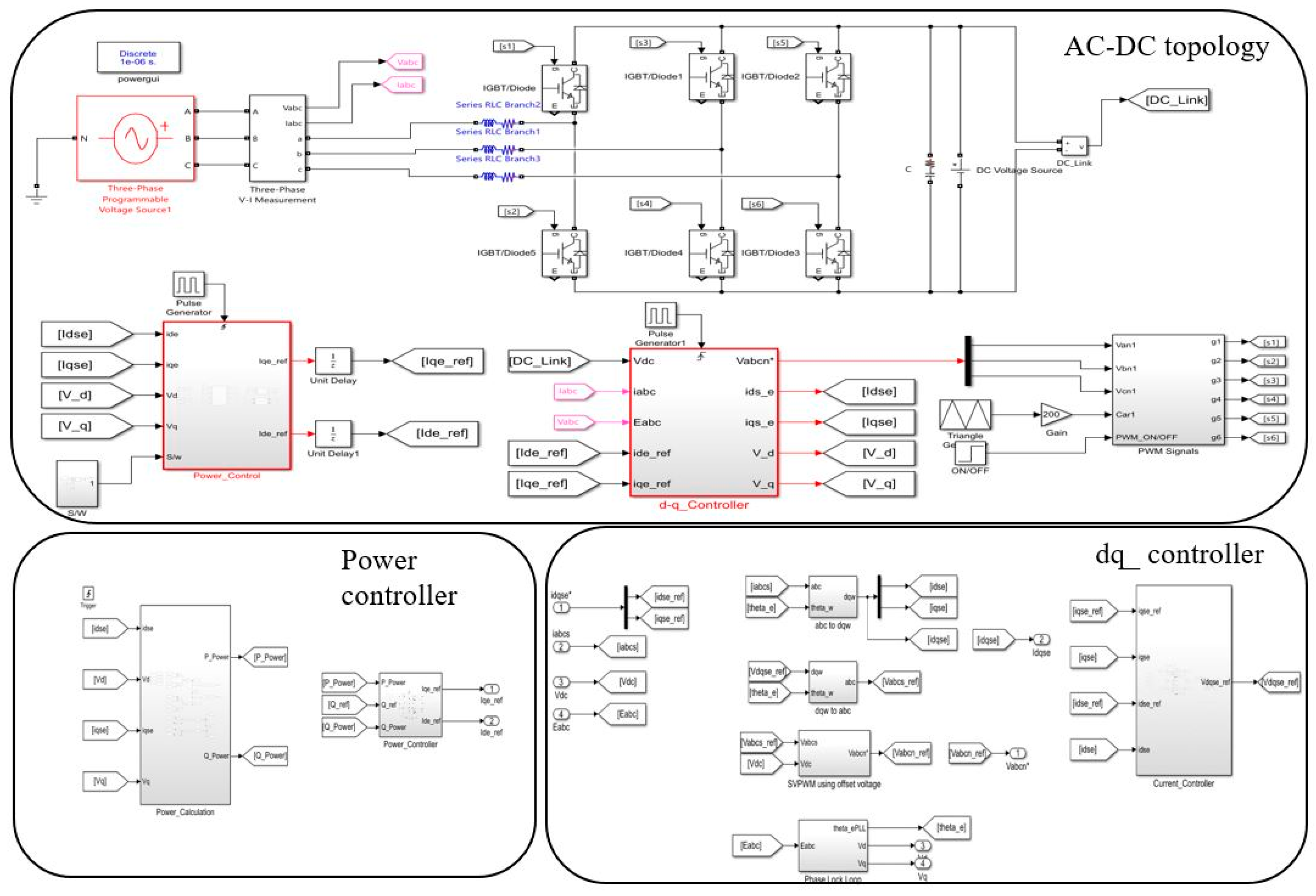
4. HILS Verification

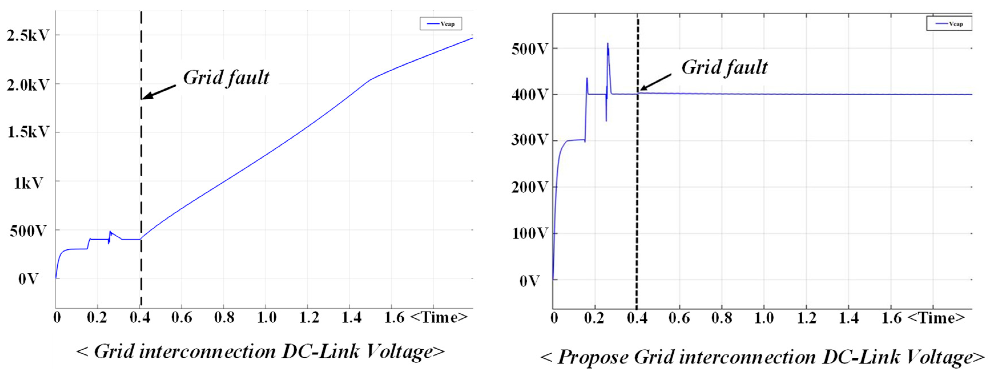
4.1. Verification of DC_Link Stabilization HILS of Grid-Connected Devices through Dynamic Grid Support

Figure 15 shows an active/reactive power control simulator for grid-connected devices implemented using HILS equipment. This control simulator is a control block diagram that generates PWM signals for the AC–DC topology, and is divided into a controller that controls the power supply and a dq controller that controls the dq. The system parameters are as shown in Table 1.
Figure 16 shows the results of the active and reactive power control of grid-connected devices. Simulation results are shown when the phase of voltage and current is in phase and when the phase of current is 90 degrees lagging or leading.
According to Figure 17, the initial grid voltage is 1 pu, where the Q_ref value is 0 kW and the P_ref value is 5 kW, indicating active power. If the voltage drop within ±10% of grid voltage is normal, Section 1 and Section 2 supply reactive power appropriately. In addition, when grid voltage exceeds −50%, leading reactive power is supplied to 100% grid in the second section. If the voltage rises by 20% over 1 pu, the lagging reactive current is supplied to the grid by limiting 40% in Section 1. Figure 18 and Figure 19 below show the simulation results of static and dynamic grid support control. The results of the dq axis according to the voltage and current in each section are shown.
As shown in Figure 20, if a fault situation occurs at 0.4 s, the DC_link voltage of general grid-connected devices rises significantly, resulting in the destruction of grid-connected devices, and cannot satisfy the Grid Code regulations. However, it can be confirmed that the DC_link voltage of the proposed grid-connected devices stays constant. As a result, it is possible to prevent the DC_link destruction of grid-connected devices and satisfy the Grid Code regulations.
The simulation was performed using the power compensator control algorithm described above, and the power compensator’s charging and power control modes were operated. Figure 21 is a power compensator simulation block diagram, it is controlled by dividing it into conversion and power calculator parts through CC-CV controller, AC-DC topology controller, dq transform. and Table 2 below shows the simulation parameter table.
Figure 22 shows the charge control mode on the supercapacitor voltage/current. Since the first supercapacitor voltage is 170 V with the supercapacitor voltage command of 200 V, it is charged in Buck mode for 0.1 s~0.8 s. If the current 50 A of the capacitor is controlled by Constant Current (CC), it is gradually decreased, and from the point of decrease, it is controlled to a Constant Voltage (CV) of 200 V. Subsequently, since it is a power control mode for 0.8 s to 1.5 s, it boosts, the current gradually decreases, and the voltage also decreases. Figure 23 shows the result of sending the supercapacitor energy to the grid by controlling the active power −6 kW and reactive power 2 kVar, and Figure 24 shows the dq-axis current simulation result within the same timeframe.

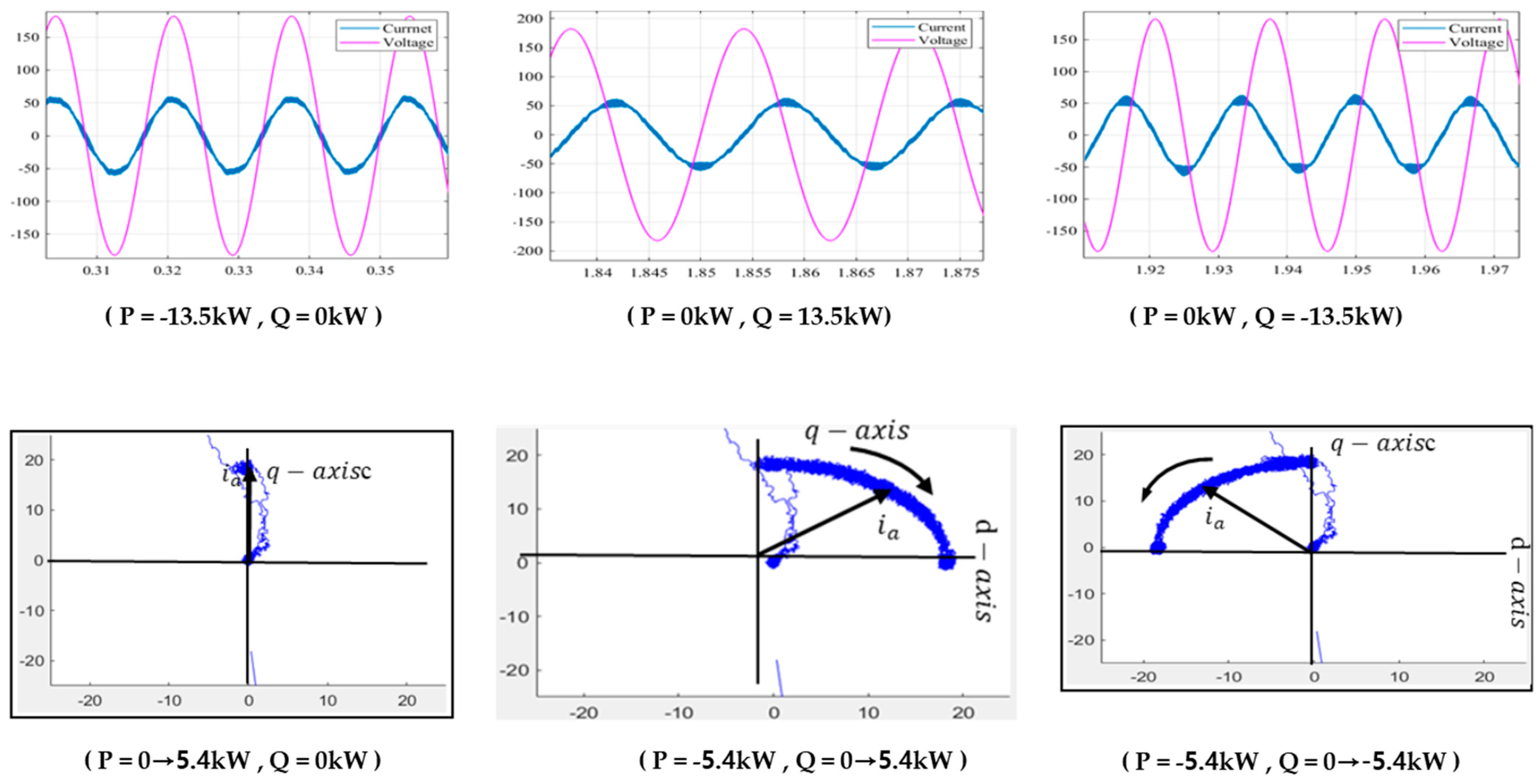
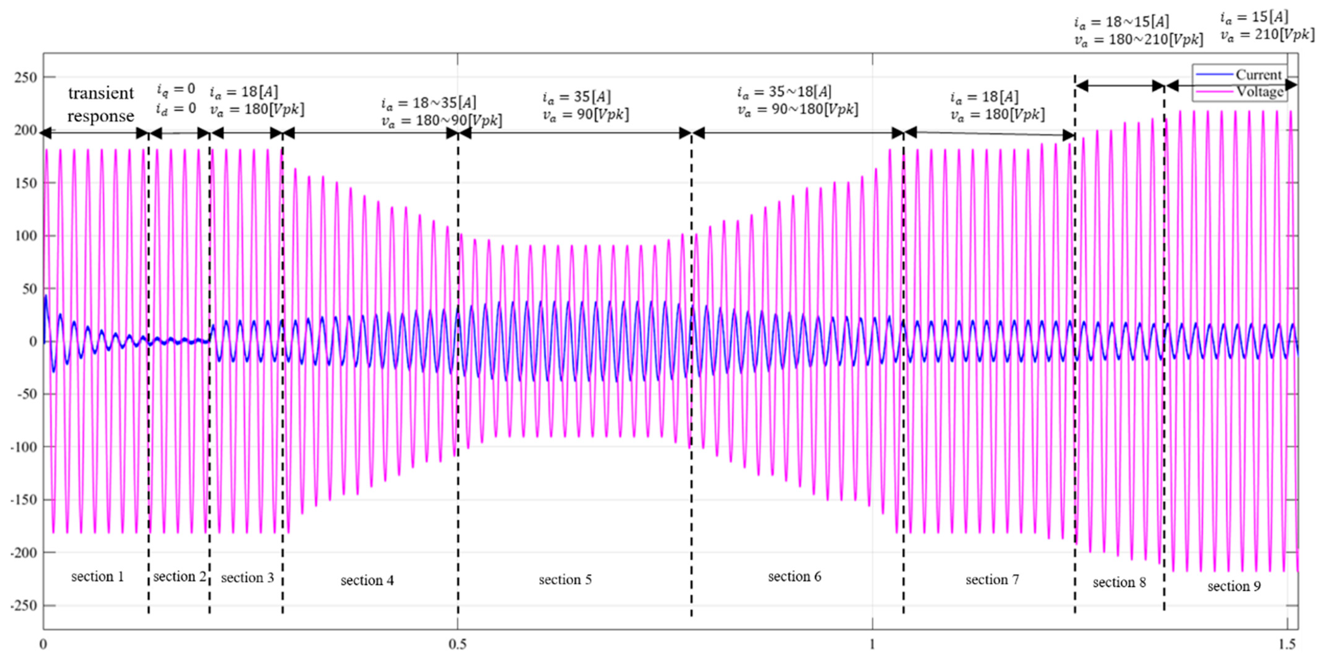
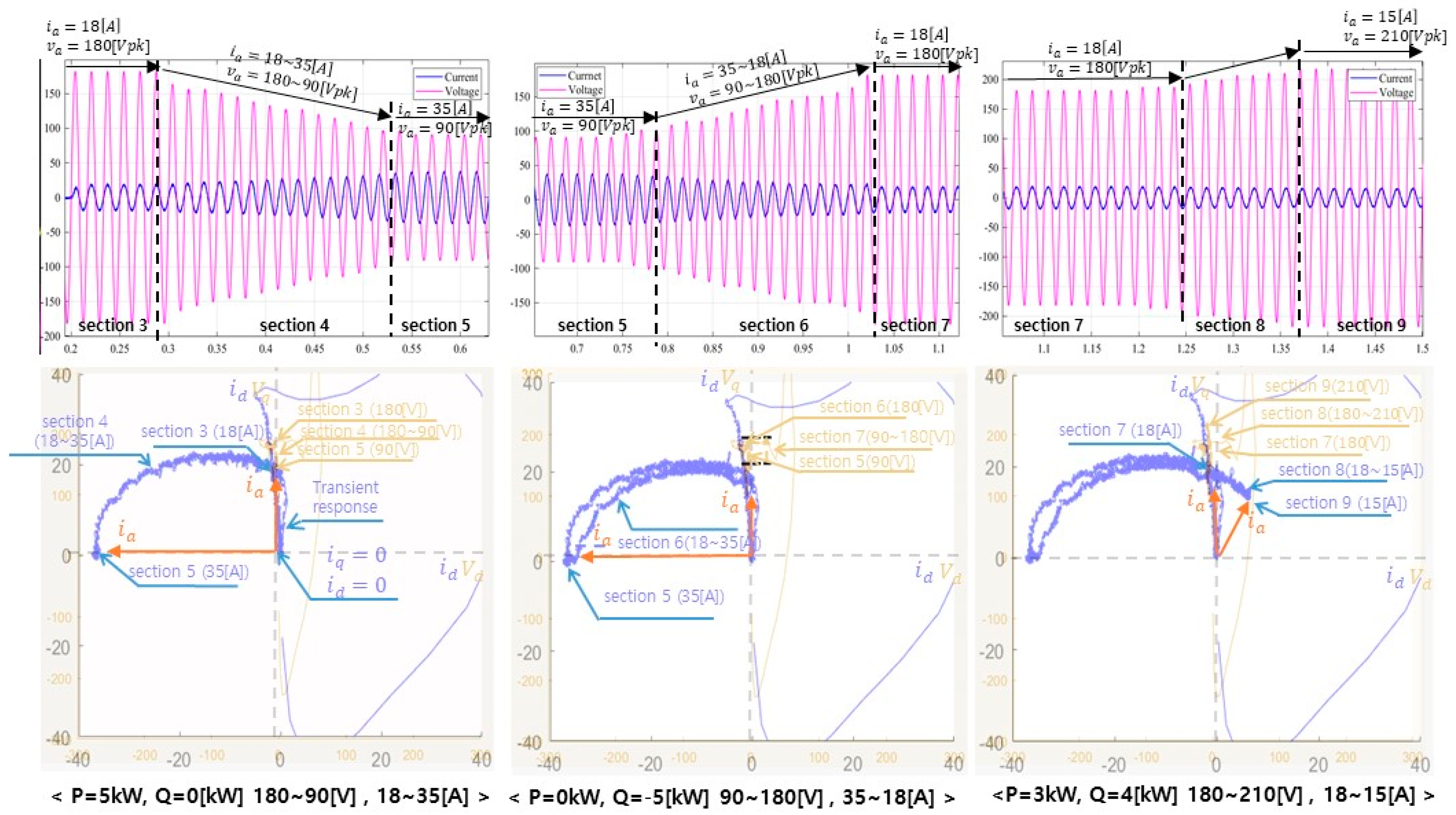
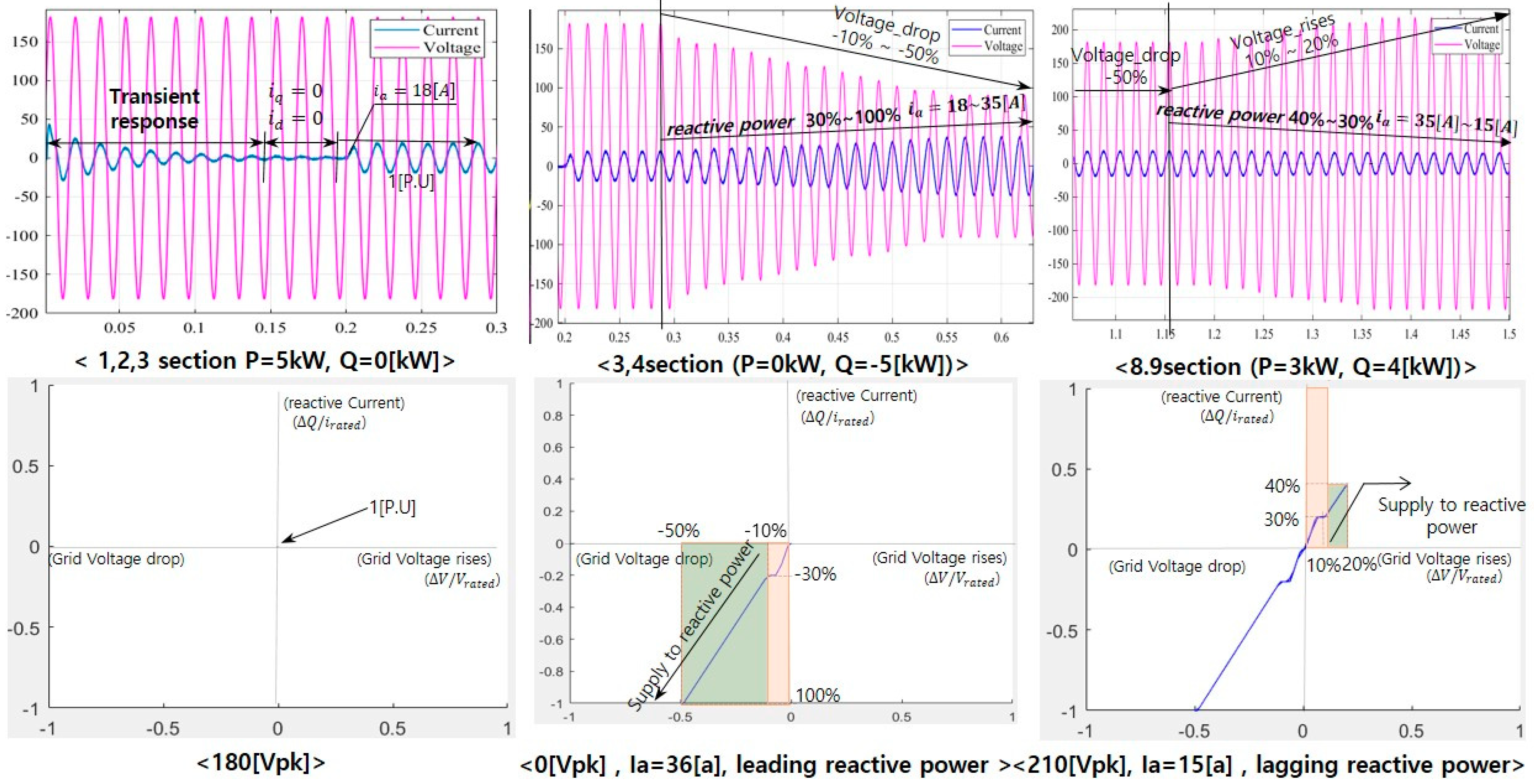
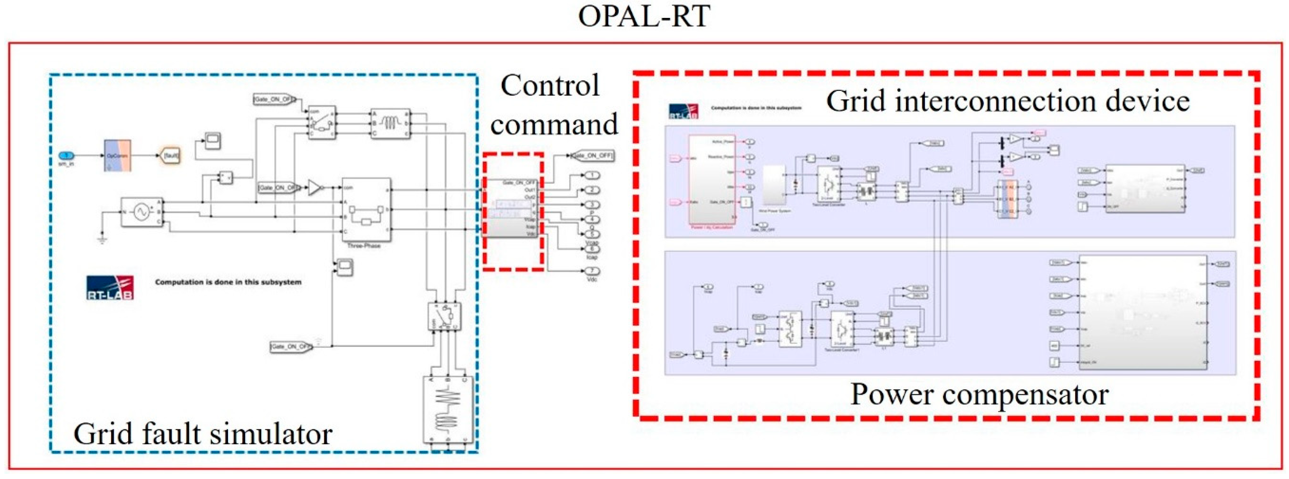
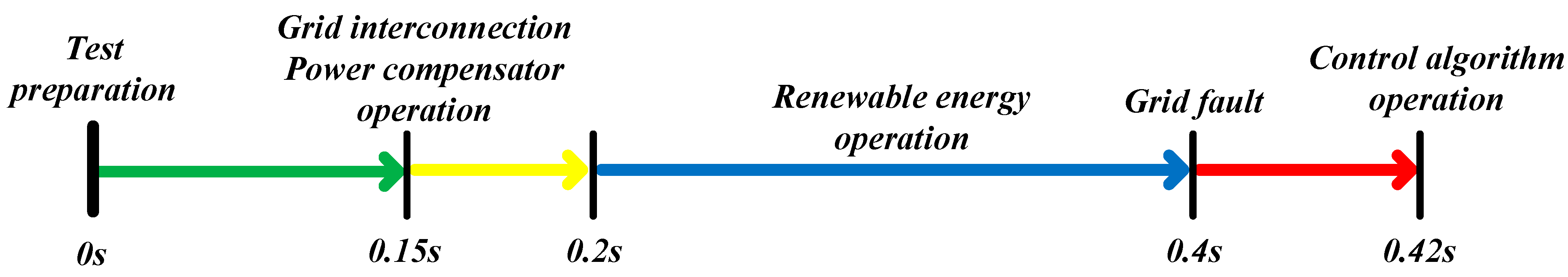
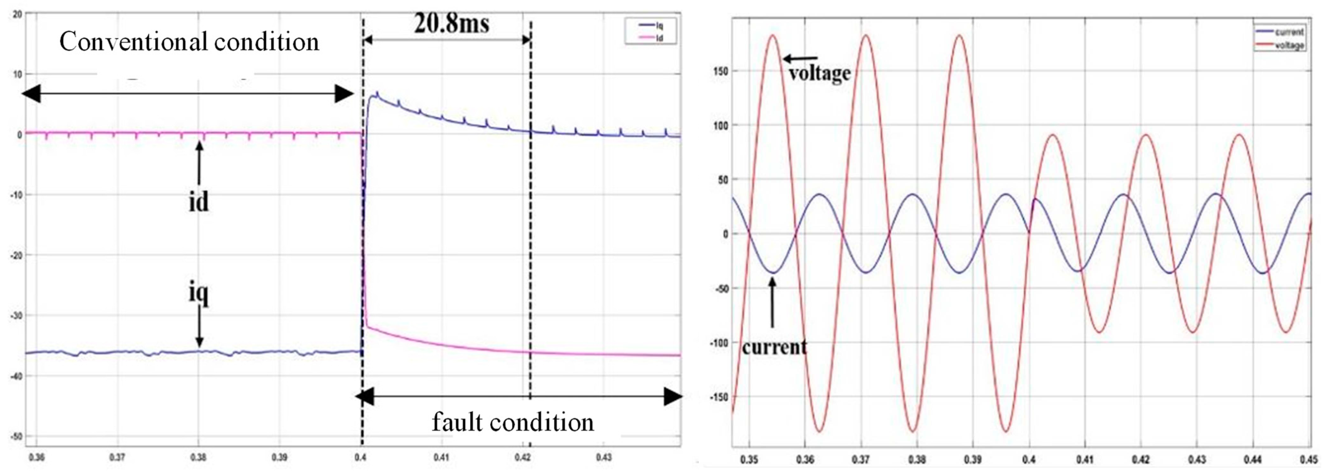
4.2. OPAL-RT Verification of Grid-Connected Devices Using Power Compensator during LVRT

During LVRT, the power generated from distributed generation causes a DC_link voltage rise, and there is a risk of destroying grid-connected devices. The power compensator designed to prevent this absorbs active power in an accident situation and stores it in a supercapacitor to suppress the DC_link voltage rise and efficiently use the power. In addition, if grid-connected devices operate independently, the response to sending reactive current to the grid in the case of grid failure has a slope, as shown by the red dotted line in Figure 25. Currently, the reactive current response is required to be within the 20 ms regulation by the German Grid Code, but this is gradually becoming faster due to the increase in distributed generation in each country.
The grid-connected devices, including the proposed power compensator, the power compensator and grid-connected devices, can compensate each i rds /2 and send it to the grid. As a result, the response time of the reactive current can be shortened more quickly, as shown by the slope of the blue line.
When the grid voltage of the proposed distributed generation grid-connected devices is in a low-voltage failure situation, and the distributed generation output is the maximum output, the active power of the generated distributed generation is effectively removed. This was investigated through the simulation of distributed generation grid-connected devices using OPAL-RT, as shown in Figure 26, to verify whether the response of reactive current required by the Grid Code can be quickly controlled. In order to simulate the system failure situation, the command was changed at one moment to simulate. To simulate an LVRT condition, a 0.5 pu drop was made at the grid voltage of 1 pu, and a simulation experiment was conducted. Table 3 below shows the system parameters for the simulation.
Figure 27, an OPAL-RT test step, shows the operation of the supercharger circuit to limit excessive current flow up to 0.15 s to charge the DC_link voltage when the OPAL-RT test is ready. After that, the DC_link voltage of the grid-connected devices was controlled to 400 V for the normal driving of the distributed generation, and the power compensator controlled the initial voltage of the supercapacitor, 200 V, through the buck mode operation. From 0.2 s, renewable energy generated power, and the system operated stably. At 0.4 s, the fault situation was simulated through the grid fault simulator, and the grid voltage was reduced by 0.5 pu. Then, it performed reactive current cooperative control of the grid-connected devices and power compensator to deliver 1 pu of reactive current to the grid. In addition, to protect the LVRT grid connection field, it was controlled to stabilize the DC_link voltage of the grid-connected devices by charging the Super Cap. After 0.02 s, which is the required time for dynamic grid support, the improvement in reactive current response was checked and compared.
When operating grid-connected devices alone without using a power compensator, a grid fault load with a response of 20 ms was designed, and the response was confirmed, as shown in Figure 28. It was designed to have a reactive current response within 10 ms through cooperative control by adding a power compensator, and Figure 29 shows the result.
First, to ensure the feasibility of improving the response, the response time of the reactive current during the single operation of grid-connected devices was verified.
For the independent operation of grid-connected devices, Figure 28 shows the response of 20.8 ms through the DC current converted to the dq axis when the voltage drop rate is decreased from 0.4 s to 0.5 pu at the voltage drop rate of 1 pu. This response satisfies 20 ms of the existing German Grid Code regulation, but as mentioned in this paper, when considering the grid regulation due to the congestion degree of distributed generation, it is the response speed that has a fundamental problem. For this, an improved response speed through the cooperative control of the power compensator is necessary. Figure 29 shows the response result through the proposed algorithm and power compensator by improving these requirements.
Figure 29 shows that the response of 6.8 ms, which is the required time according to the same voltage drop rate of 0.5 pu, improved from the existing 20.8 ms. The conditions required by the grid regulation were satisfied. By controlling the fast response speed with this cooperative control, it is possible to strategize the strengthened regulations due to the increase in distributed generation and the congestion degree of the grid and suppress the destruction of grid-connected devices.

5. Conclusions

In this paper, we designed a power compensator using supercapacitors in parallel to protect the grid-connected devices connected to the distributed generation for a possible LVRT situation and verified the results of the grid-connected device control method with an improved response. The power compensator absorbed the active power in an accident situation and stored it in the supercapacitor to suppress the DC_link voltage rise and efficiently use the power. In LVRT, the system was checked through a grid variable due to dynamic grid support, and it was confirmed that the grid compensation and reactive current response improved from 20 ms to 6.8 ms. In this way, it was possible to stabilize grid-connected devices by suppressing the DC_link voltage rise. The experimental progress of this paper proves the validity of the OPAL-RT-based HILS simulation to perform grid voltage fluctuations. However, its feasibility can be demonstrated more clearly if a user experiments by controlling the grid voltage decrease/increase rate.

Author Contributions

M.-n.K. and J.-H.L. conceived and designed the theory and experiment; M.-n.K. wrote the manuscript; C.-Y.W. and J.-s.Y. participated in research plan development and revised the manuscript. All authors have read and agreed to the published version of the manuscript.

Funding

This research received no external funding.

Acknowledgments

This work was supported by the Korea Institute of Energy Technology Evaluation and Planning (KETEP) and the Ministry of Trade, Industry and Energy (MOTIE) of the Republic of Korea (no. 2019381010001B). This research was supported by Gunsan City, Korea, under the Human Resources Program for the EV industrial cluster.

Conflicts of Interest

The authors declare no conflict of interest.

References

  1. Xuewei, S.; Xuefang, S.; Wenqi, D.; Peng, Z.; Jia, H.; Wu, J.; Wang, Y. Research on Energy Storage Configuration Method Based on Wind and Solar Volatility. In Proceedings of the 2020 10th Inter-national Conference on Power and Energy Systems (ICPES), Chengdu, China, 25–27 December 2020; pp. 464–468. [Google Scholar] [CrossRef]
  2. “Renewables 2019: Global Status Report (grs). 2019”. REN21. 2019. Available online: http://www.ren21.net8/. (accessed on 16 February 2022).
  3. De Paula Silva, R.; da Silveira, D.B.; de Barros, R.C.; Callegari, J.M.S.; Cupertino, A.F.; Pereira, H.A. Third-Harmonic Current Injection for Wear-out Reduction in Single-Phase PV Inverters. IEEE Trans. Energy Convers. 2021, 37, 120–131. [Google Scholar] [CrossRef]
  4. Jebaselvi, G.D.A.; Paramasivam, S. Analysis on renewable energy systems. Renew. Sustain. Energy Rev. 2013, 28, 625–634. [Google Scholar] [CrossRef]
  5. IEEE Std 1547–2018 (Revision of IEEE Std 1547–2003)-Redline; IEEE Standard for Interconnection and Interoperability of Distributed Energy Resources with Associated Electric Power Systems Interfaces—Redline. IEEE: New York, NY, USA, 6 April 2018.
  6. Nakadomari, A.; Shigenobu, R.; Senjyu, T. Optimal Control and Placement of Step Voltage Regulator for Voltage Unbalance Improvement and Loss Minimization in Distribution System. In Proceedings of the 2020 IEEE Region 10 Conference (Tencon), Osaka, Japan, 16–19 November 2020; pp. 1013–1018. [Google Scholar] [CrossRef]
  7. Pradhan, C.; Bhende, C.N.; Samanta, A.K. Adaptive virtual inertia-based frequency regulation in wind power systems. Renew. Energy 2018, 115, 558–574. [Google Scholar] [CrossRef]
  8. Causebrook, A.; Atkinson, D.J.; Jack, A.G. Fault Ride-Through of Large Wind Farms Using Series Dynamic Braking Resistors. IEEE Trans. Power Syst. 2007, 22, 966–975. [Google Scholar] [CrossRef]
  9. Chandrasekaran, S.; Rossi, C.; Casadei, D.; Tani, A. Improved control strategy of wind turbine with DFIG for Low Voltage Ride Through capability. In Proceedings of the International Symposium on Power Electronics Power Electronics, Electrical Drives, Automation and Motion, Sorrento, Italy, 20–22 June 2012; pp. 19–24. [Google Scholar]
  10. Shin, H.; Jung, H.; Sul, S. Low Voltage Ride Through(LVRT) control strategy of grid-connected variable speed Wind Turbine Generator System. In Proceedings of the 8th International Conference on Power Electronics-ECCE Asia, Jeju, Korea, 30 May–3 June 2011; pp. 96–101. [Google Scholar] [CrossRef]
  11. Bae, Y.; Vu, T.; Kim, R. Implemental Control Strategy for Grid Stabilization of Grid-Connected PV System Based on German Grid Code in Symmetrical Low-to-Medium Voltage Network. IEEE Trans. Energy Convers. 2013, 28, 619–631. [Google Scholar] [CrossRef]
  12. Safayet, A.; Fajri, P.; Husain, I. Reactive Power Management for Overvoltage Prevention at High PV Penetration in a Low-Voltage Distribution System. IEEE Trans. Ind. Appl. 2017, 53, 5786–5794. [Google Scholar] [CrossRef]
  13. Jiancheng, T.; Haili, G.; Guangzong, C. LVRT control strategy of VSC-HVDC connected large PV plant. In Proceedings of the 2017 China International Electrical and Energy Conference (CIEEC), Beijing, China, 25–27 October 2017; pp. 504–509. [Google Scholar] [CrossRef]
  14. E. ON NETZ GmbH. Grid Code for High and Extra High Voltage; E.ON Netz: Essen, Germany, 2006. [Google Scholar]
  15. Batreuth, G.H. Requirements for Offshore Grid Connections in the E.ON Netz Network; E.ON Netz: Essen, Germany, 2008. [Google Scholar]
  16. Transmission Code 2007-Network and System Rules of the German Transmission System Operators; Verband der Netzbetreiber VDN e.V.beim VDEW: Berlin, Germany, 2007.
  17. Yang, Y.; Blaabjerg, F. Low-voltage ride-through capability of a single-stage single-phase photovoltaic system connected to the low-voltage grid. Int. J. Photoenergy 2013, 2013, 257487. [Google Scholar] [CrossRef] [Green Version]
  18. Noureldeen, O.; Youssef, M.M.M. Super-capacitor utilization for low- voltage ride through improvement of grid-tied wind turbines. In Proceedings of the 2017 Nineteenth International Middle East Power Systems Conference (MEPCON) in Power Systems Conference (MEPCON), Cairo, Egypt, 19–21 December 2017; pp. 1305–1309. [Google Scholar]
  19. Anwar, A.; Ali, M.H.; Dougal, R.A. Supercapacitor energy storage for low-voltage ride through in a 13.8 KV AC system. In Proceedings of the IEEE SoutheastCon 2010 (SoutheastCon), Concord, NC, USA, 18–21 March 2010; pp. 189–192. [Google Scholar]
  20. Patil, S.B.; Pawar, A.S. Stability Analysis of Supercapacitor based DC Microgrid System with Energy Storage. In Proceedings of the 2020 IEEE International Conference for Innovation in Technology (INOCON), Bangluru, India, 6–8 November 2020; pp. 1–4. [Google Scholar] [CrossRef]
  21. Ryu, H.-Y.; Kim, J.A.; Sul, S.E. Analysis of multiphase space vector pulse-width modulation based on multiple d-q spaces concept. IEEE Trans. Power Electron. 2005, 20, 1364–1371. [Google Scholar] [CrossRef]
Figure 1. Requirements for FRT by German Grid Code.
Electronics 11 01144 g001
Figure 2. German Grid Code: (a) principle of grid voltage support; (b) reactive current to grid voltage regulation.
Electronics 11 01144 g002
Figure 3. DC_link voltage fluctuation in each situation: (a) steady condition; (b) LVRT condition.
Electronics 11 01144 g003
Figure 4. Full block diagram of power compensators and grid-connected devices.
Electronics 11 01144 g004
Figure 5. Equivalent circuit of 3-phase AC–DC converter.
Electronics 11 01144 g005
Figure 6. dq axis vector control.
Electronics 11 01144 g006
Figure 7. Control block diagram of grid-connected devices in distributed generation.
Electronics 11 01144 g007
Figure 8. Calculation block diagram for distributed power generation.
Electronics 11 01144 g008
Figure 9. Detailed block diagram of a power distributor.
Electronics 11 01144 g009
Figure 10. Three-phase grid voltage and current phasor diagram.
Electronics 11 01144 g010
Figure 11. Size of reactive power according to active power.
Electronics 11 01144 g011
Figure 12. Calculation of compensation power supercapacitor.
Electronics 11 01144 g012
Figure 13. Algorithm block diagram for power compensator control.
Electronics 11 01144 g013
Figure 14. Block diagram for the charging control mode of a power compensator.
Electronics 11 01144 g014
Figure 15. Active/reactive power control simulator for grid-connected devices.
Electronics 11 01144 g015
Figure 16. Results of active and reactive power control of grid-connected devices.
Electronics 11 01144 g016
Figure 17. Overall graph of varying grid voltage and current.
Electronics 11 01144 g017
Figure 18. Results of simulation experiment for each variable section of grid voltage and current.
Electronics 11 01144 g018
Figure 19. Comparison of dynamic grid support and simulation test results for each section.
Electronics 11 01144 g019
Figure 20. DC_link voltage.
Electronics 11 01144 g020
Figure 21. Simulation block diagram of power compensator control.
Electronics 11 01144 g021
Figure 22. Simulation results of supercapacitor voltage/current.
Electronics 11 01144 g022
Figure 23. Simulation results of active/reactive power.
Electronics 11 01144 g023
Figure 24. Simulation results of dq axis current.
Electronics 11 01144 g024
Figure 25. Response of proposed grid-connected devices for distributed generation.
Electronics 11 01144 g025
Figure 26. OPAL-RT block diagram of a grid-connected device including the proposed power compensator.
Electronics 11 01144 g026
Figure 27. OPAL-RT test step.
Electronics 11 01144 g027
Figure 28. Phase voltage, current, and reactive current response results for independent operation depending on grid voltages.
Electronics 11 01144 g028
Figure 29. Response results of the proposed grid-connected devices depending on grid voltages.
Electronics 11 01144 g029
Table 1. Three-phase system parameters.
ParameterValueUnit
Grid Voltage380Vac
Grid Frequency60Hz
Apparent Power5kva
Output Filter1mH
DC_link_Cap4700μF
DC_link Voltage400Vdc
Switching Frequency10kHz
Table 2. Power compensator simulation parameters.
Mode SelectionPower CommandCharging Control Mode Charging CurrentCharging Control Mode
Charging Voltage
Power control mode 0.8~1.5 sActive power −6 kW50 A200 V
Charging control mode 0.1~0.8 sReactive power 2 kVar
Table 3. OPAL-RT parameters for grid-connected devices with power compensators.
ParameterValueUnit
Grid Voltage220Vrms
Grid Frequency60Hz
Control Period50μs
Apparent Power5kva
Supercapacitor10mF
Grid Connected 3 ph. Reactor5mH
DC/DC Converter Reactor2mH
Publisher’s Note: MDPI stays neutral with regard to jurisdictional claims in published maps and institutional affiliations.

