
An Omnidirectional Platform for Education and Research in Cooperative Robotics


Abstract
:1. Introduction
2. Description of Implemented System
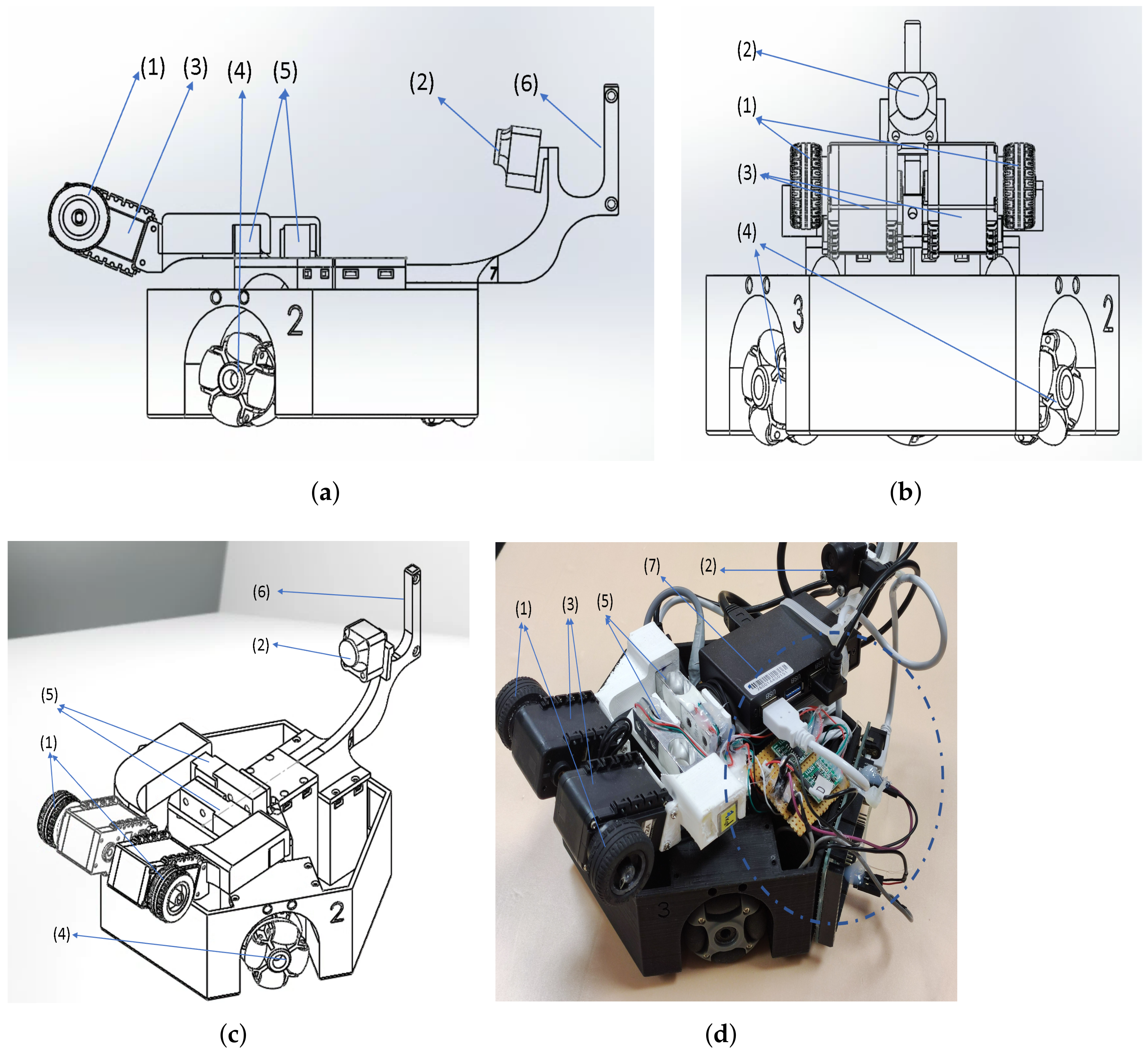
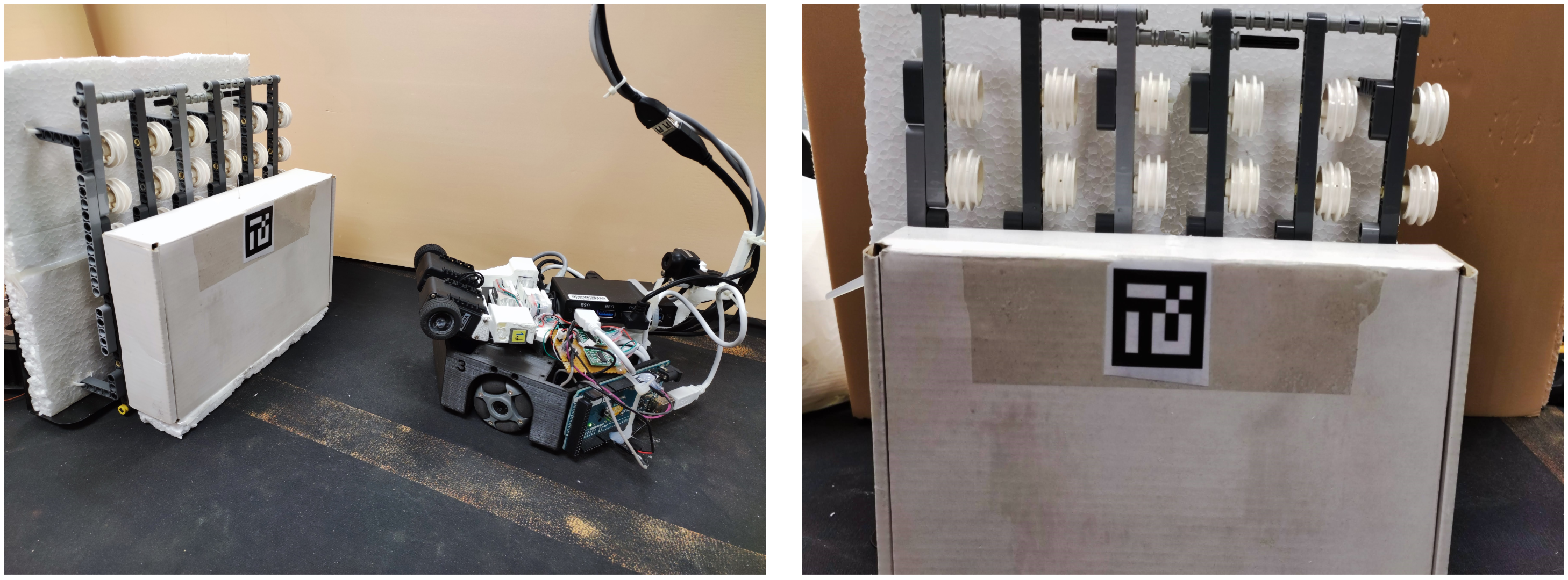
2.1. Hardware Platform
2.2. Controller Software
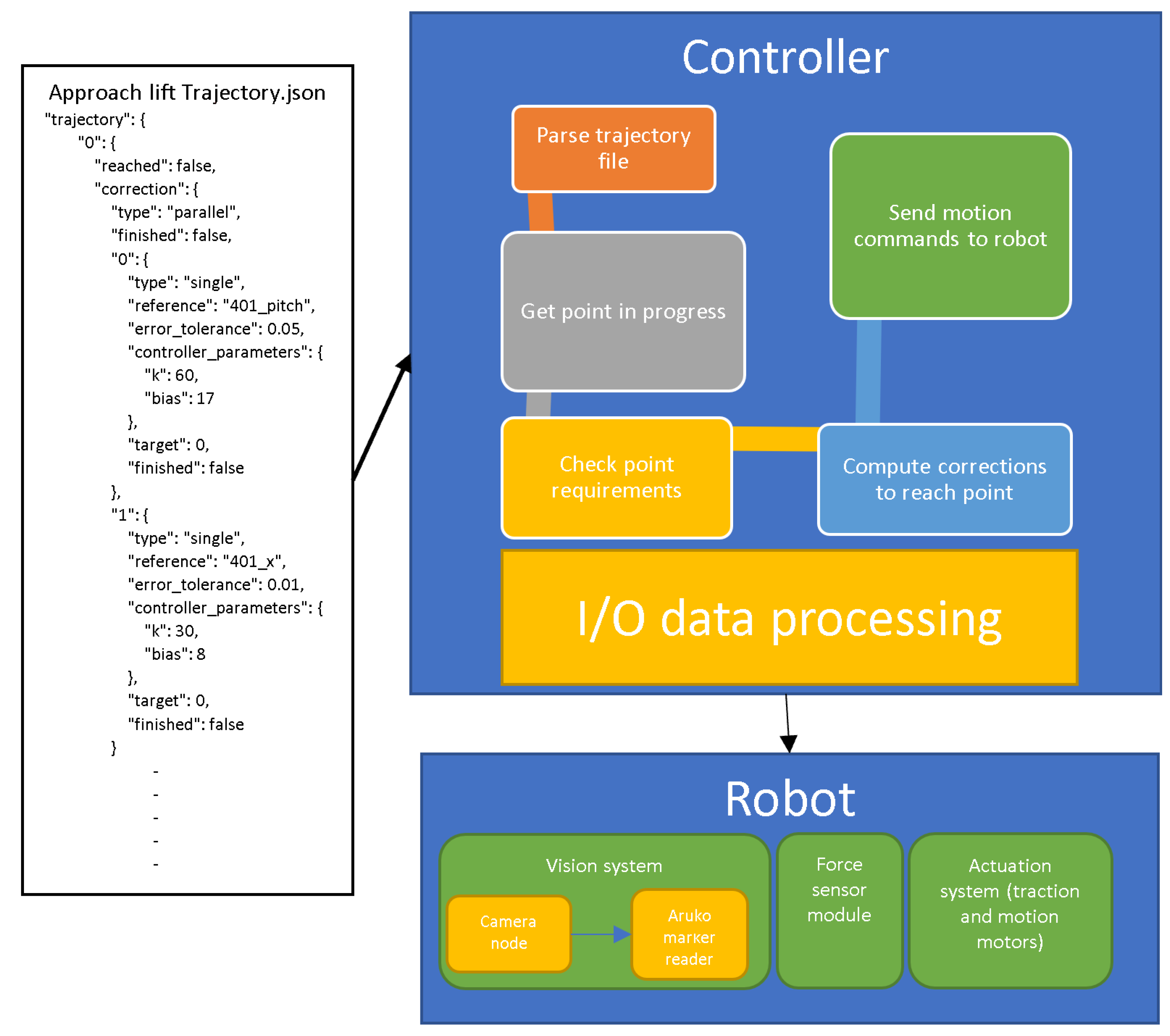
2.2.1. Overview
- Single: this indicates one correction is going to be processed. This is usually the leaf type for single access corrections;
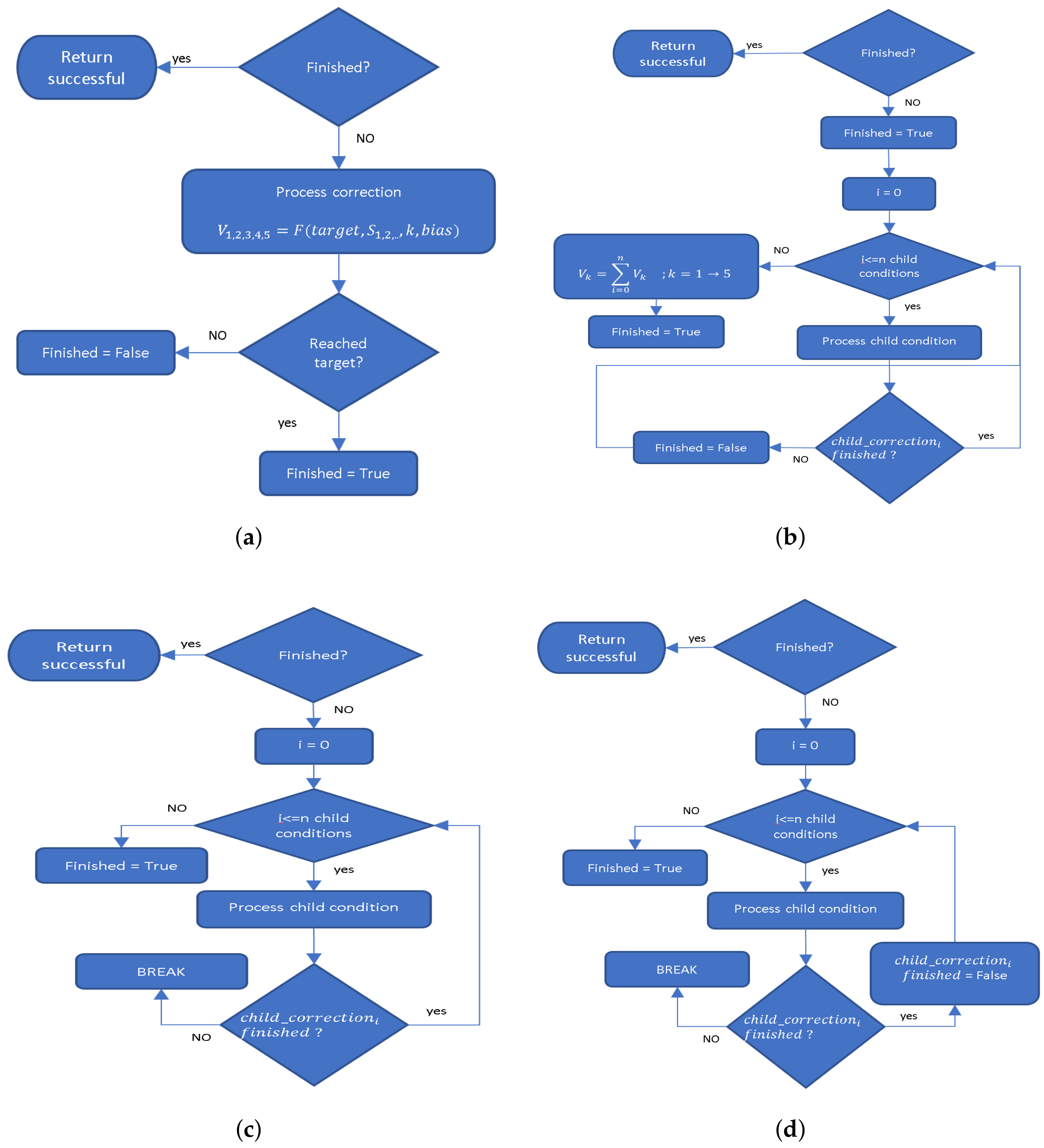
- Sequential: this indicates that child conditions will be processed sequentially. Once the correction is done, the controller will not check this condition again;
- Parallel: child conditions will be processed at the same time so in each tick all the child corrections are processed and the result output is calculated from the outputs of all child corrections;
- Semi-sequential: in one tick, the controller goes over child corrections sequentially, calculates the first unfinished correction, ignores the rest, and outputs the result. This means that each time, the controller will not proceed to next condition until it has fixed the first ones. The difference with sequential is that this method checks the finished child corrections each tick for any new deviation from target.
2.2.2. Available Types of Conditions
- Planar conditions: the conditions are to meet certain position(X,Y)/orientation(Alpha) relative to a reference frame (the marker in our case);
- Boolean: target value is True/False;
- Time (wait): target is reached after certain time;
- Force (single access): target is reached when force sensor reading reach set target.
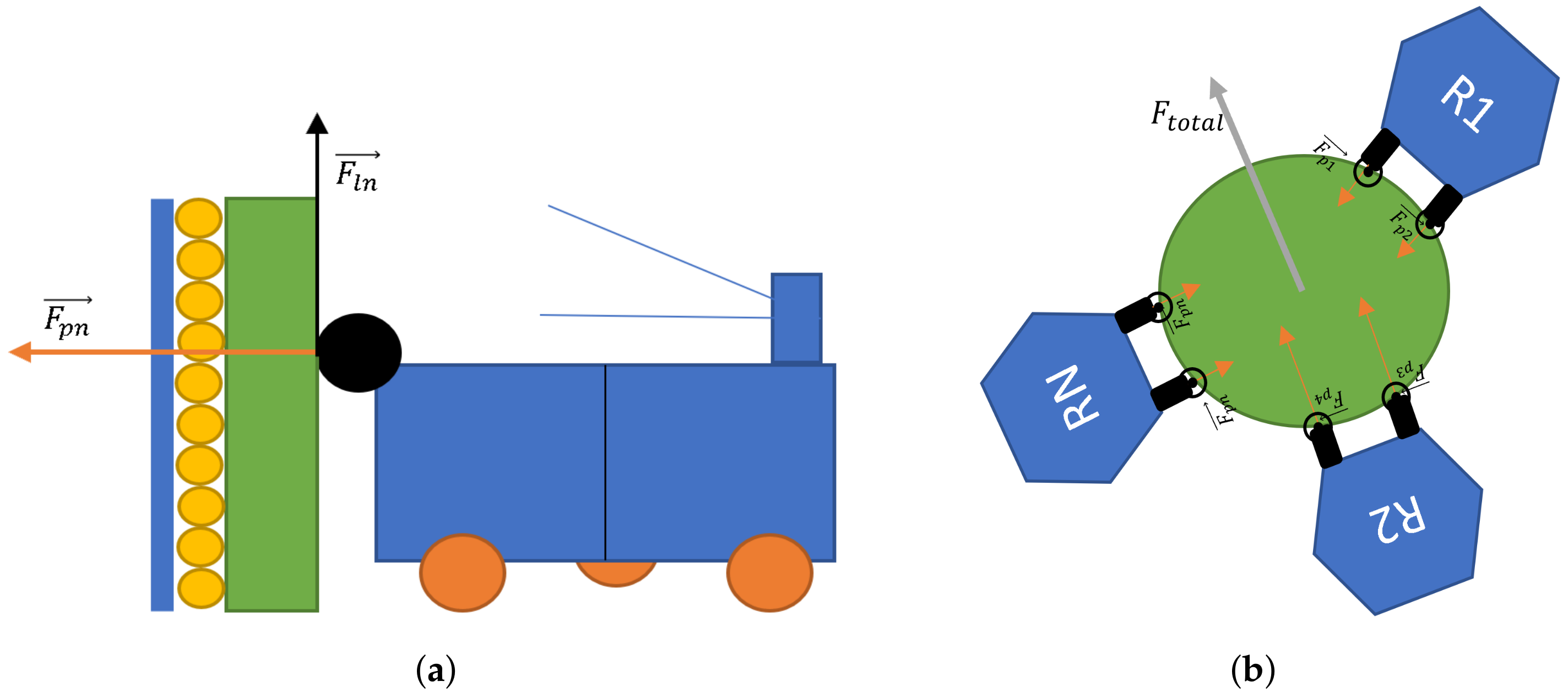
- Total pressure collected from both sensors is within allowed range. This is corrected by moving the robot forward;
- Difference between force sensors readings is below a certain tolerance, which is corrected by rotating the robot while applying pressure on target object.
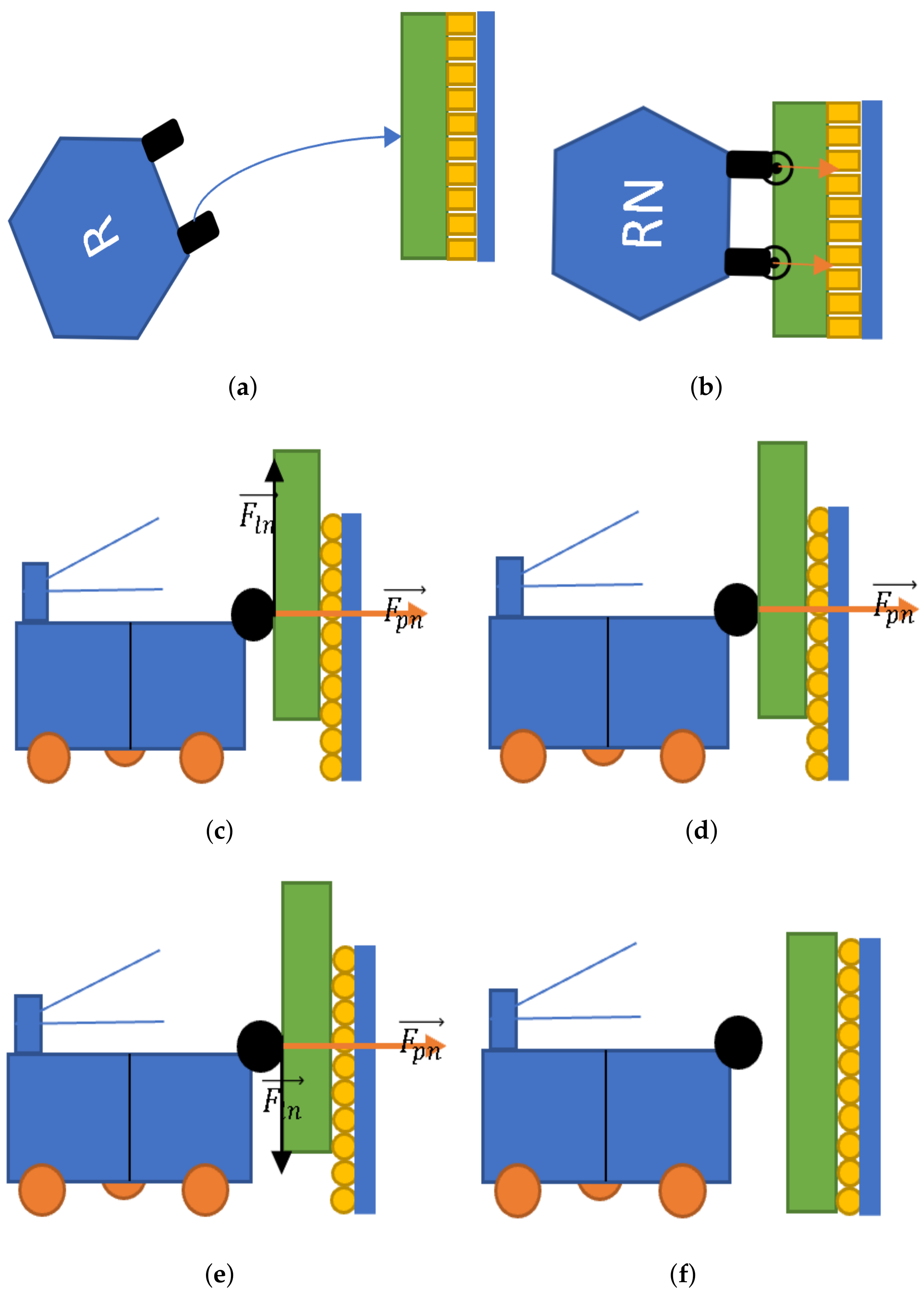
3. Concept, Approach, and Considerations
4. Experiments and Results
4.1. Experiment 1
4.1.1. Description
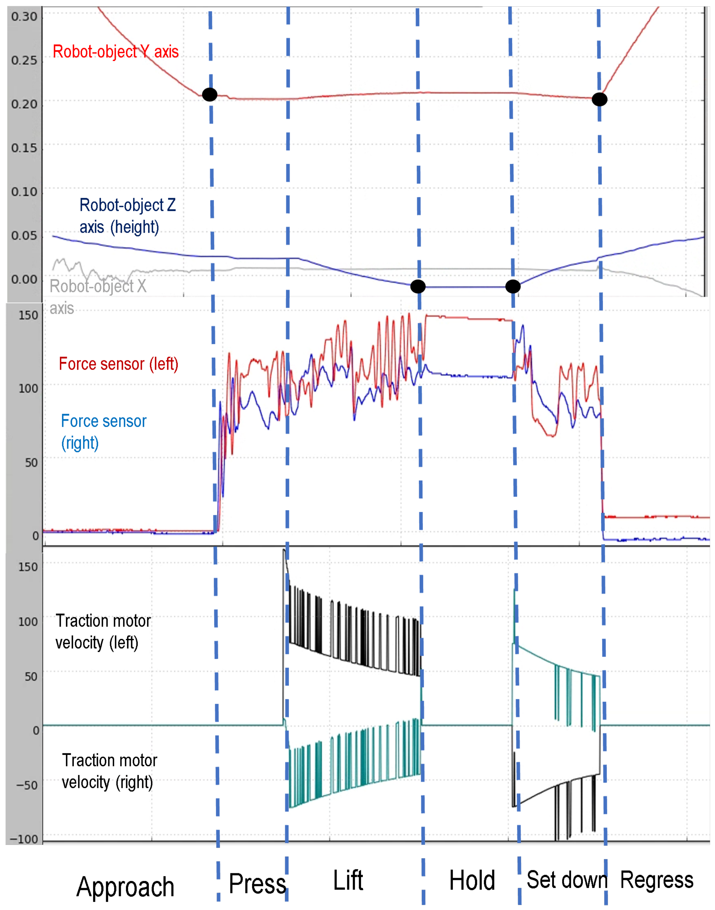
- Approach: the robot starts in a random location where the target object is visually accessible. The robot detects the target object and performs parallel control to reach a 2 cm distance from the object while keeping the robot parallel and centered relative to the target object.*When at the target, the robot calibrates the height of the target object marker and starts next correction;
- Press: having the robot perfectly parallel to the opposing surface, the system sets the target pressure to 120 g with a total tolerance of 40 g. Once the system reads force values in this range, the target object is “grasped” and ready to be lifted;
- Lift: the trajectory specifies the system to perform parallel control to lift the object up 4 cm using the traction wheels in front while maintaining the same pressure and keeping the target bottom surface parallel to the ground. Please note that the Z axis value is inverted;
- Hold: the robot holds the object in the same conditions for 5 s adding a time constraint to the previous parallel control. Note that in this phase, the control is already stable and, since there are not changes on the inputs, the system does not react;
- Set down: keeping force conditions but changing the target height to original, the robot lowers down the target object;
- Regress: now the robot can release pressure of the object and leave the area.
4.1.2. Results
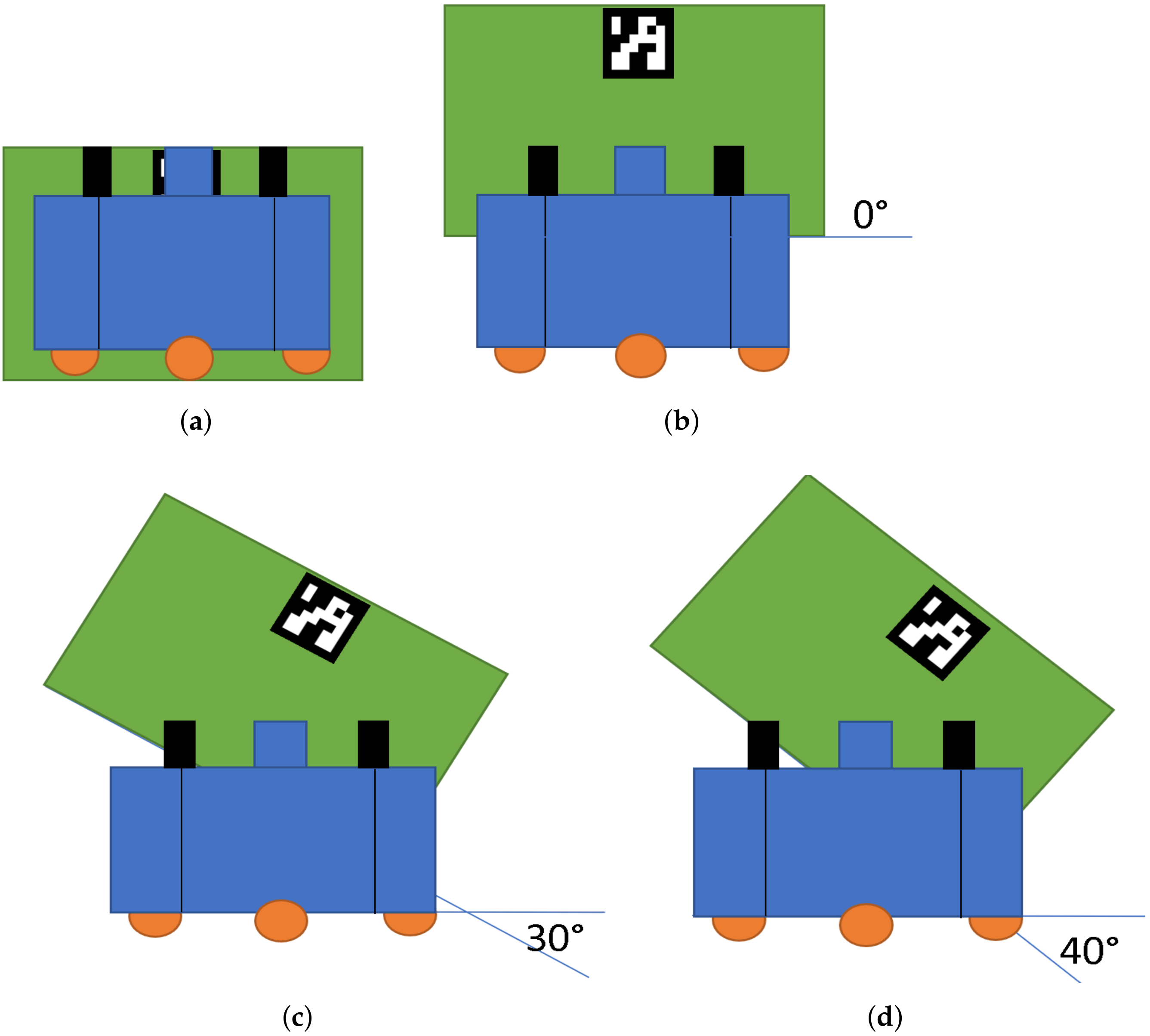
4.2. Experiment 2
4.2.1. Description
4.2.2. Results
4.3. Experiment 3
4.3.1. Description
4.3.2. Results
5. Discussion and Conclusions
- Maximum manipulation angle: as shown in Experiment 2, with more than 20 degree angle the system would have a high failure rate since the object is no longer gaining traction from the wheels’ pressure. This issue can be solved by having more traction points with higher altitude so that the lifted object is always in contact with at least two points. Nevertheless, the solution was not implemented because the current limit is more than enough to perform a stable operation at maximum lift height;
- Pressure overshooting: in all experiments, it has been noted that our system tends to overshoot the pressure set point. This is due to the relatively high minimum speed of the used servo motors. Although this does not affect the overall results of the system, it has introduced a certain complexity to the process of tuning the low level controller constants to be able to overcome this issue;
- Maximum pressure limit: our 3D experiment draws the maximum pressure limit at 120 g. This value correlates with the maximum weight of the object that can be lifted (around 500 g). Counter-intuitively, the problem does not arise from the torque of the wheel motors, but arises from not having enough friction with the ground. The performance could be effortlessly improved by adding passive weight to the robot, increasing its friction force and, therefore, its lifting capacity.
Author Contributions
Funding
Data Availability Statement
Conflicts of Interest
References
- Tuci, E.; Alkilabi, M.H.M.; Akanyeti, O. Cooperative Object Transport in Multi-Robot Systems: A Review of the State-of-the-Art. Front. Robot. AI 2018, 5, 59. [Google Scholar] [CrossRef] [PubMed]
- Fink, J.; Hsieh, M.A.; Kumar, V. Multi-robot manipulation via caging in environments with obstacles. In Proceedings of the 2008 IEEE International Conference on Robotics and Automation, Pasadena, CA, USA, 19–23 May 2008; pp. 1471–1476. [Google Scholar] [CrossRef]
- Chen, J.; Gauci, M.; Li, W.; Kolling, A.; Groß, R. Occlusion-Based Cooperative Transport with a Swarm of Miniature Mobile Robots. IEEE Trans. Robot. 2015, 31, 307–321. [Google Scholar] [CrossRef]
- Farivarnejad, H.; Wilson, S.; Berman, S. Decentralized sliding mode control for autonomous collective transport by multi-robot systems. In Proceedings of the 2016 IEEE 55th Conference on Decision and Control (CDC), Las Vegas, NV, USA, 12–14 December 2016; pp. 1826–1833. [Google Scholar] [CrossRef]
- Gross, R.; Dorigo, M. Towards group transport by swarms of robots. Int. J. Bio-Inspired Comput. 2009, 1, 1–13. [Google Scholar] [CrossRef]
- Hichri, B.; Fauroux, J.-C.; Adouane, L.; Doroftei, I.; Mezouar, Y. Design of cooperative mobile robots for co-manipulation and transportation tasks. Robot. Comput. Manuf. 2019, 57, 412–421. [Google Scholar] [CrossRef]
- Hichri, B.; Adouane, L.; Fauroux, J.-C.; Mezouar, Y.; Doroftei, I. Flexible co-manipulation and transportation with mobile multi-robot system. Assem. Autom. 2019, 39, 422–431. [Google Scholar] [CrossRef]
- Mellinger, D.; Shomin, M.; Michael, N.; Kumar, V. Cooperative Grasping and Transport Using Multiple Quadrotors. In Distributed Autonomous Robotic Systems; Springer Tracts in Advanced Robotics; Springer: Berlin/Heidelberg, Germany, 2013; Volume 83. [Google Scholar] [CrossRef]
- Kim, S.; Seo, H.; Shin, J.; Kim, H.J. Cooperative Aerial Manipulation Using Multirotors with Multi-DOF Robotic Arms. IEEE/ASME Trans. Mechatron. 2018, 23, 702–713. [Google Scholar] [CrossRef]
- Wang, Z.; Schwager, M. Kinematic multi-robot manipulation with no communication using force feedback. In Proceedings of the 2016 IEEE International Conference on Robotics and Automation (ICRA), Stockholm, Sweden, 16–21 May 2016; pp. 427–432. [Google Scholar] [CrossRef]
- Alonso-Mora, J.; Knepper, R.; Siegwart, R.; Rus, D. Local motion planning for collaborative multi-robot manipulation of deformable objects. In Proceedings of the IEEE International Conference on Robotics and Automation, Seattle, WA, USA, 26–30 May 2015; pp. 5495–5502. [Google Scholar] [CrossRef]
- Alonso-Mora, J.; Baker, S.; Rus, D. Multi-robot formation control and object transport in dynamic environments via constrained optimization. Int. J. Robot. Res. 2017, 36, 1000–1021. [Google Scholar] [CrossRef]
- Bischoff, R.; Huggenberger, U.; Prassler, E. KUKA youBot-a mobile manipulator for research and education. In Proceedings of the 2011 IEEE International Conference on Robotics and Automation (ICRA), Shanghai, China, 9–13 May 2011. [Google Scholar]
- McLurkin, J.; McMullen, A.; Robbins, N.; Habibi, G.; Becker, A.; Chou, A.; Li, H.; John, M.; Okeke, N.; Rykowski, J.; et al. A robot system design for low-cost multi-robot manipulation. In Proceedings of the 2014 IEEE/RSJ International Conference on Intelligent Robots and Systems, Chicago, IL, USA, 14–18 September 2014; pp. 912–918. [Google Scholar] [CrossRef]
- Campbell, E.; Kong, Z.C.; Hered, W.; Lynch, A.J.; O’Malley, M.K.; McLurkin, J. Design of a low-cost series elastic actuator for multi-robot manipulation. In Proceedings of the 2011 IEEE International Conference on Robotics and Automation, Shanghai, China, 9–13 May 2011; pp. 5395–5400. [Google Scholar] [CrossRef]
- Kassawat, M.; Cervera, E.; del Pobil, A.P. Multi-robot user interface for cooperative transportation tasks. In From Bioinspired Systems and Biomedical Applications to Machine Learning; Springer: Berlin/Heidelberg, Germany, 2019; pp. 77–81. ISBN 978-3-030-19650-9. [Google Scholar] [CrossRef]
- Doroftei, I.; Grosu, V.; Spinu, V. Omnidirectional Mobile Robot – Design and Implementation. In Bioinspiration and Robotics: Walking and Climbing Robots; Habib, M.K., Ed.; I-Tech: Vienna, Austria, September 2007; p. 544. ISBN 978-3-902613-15-8. [Google Scholar]
- Sharbafi, M.A.; Indiveri, G. Swedish Wheeled Omnidirectional Mobile Robots: Kinematics Analysis and Control. IEEE Trans. Robot. 2009, 25, 164–171. [Google Scholar]
- West, M.; Asada, H. Design of Ball Wheel Mechanisms for Omnidirectional Vehicles With Full Mobility and Invariant Kinematics. J. Mech. Des. 1997, 119, 153–161. [Google Scholar] [CrossRef]
- Lebosse, C.; Renaud, P.; Bayle, B.; De Mathelin, M. Modeling and Evaluation of Low-Cost Force Sensors. IEEE Trans. Robot. 2011, 27, 815–822. [Google Scholar] [CrossRef]


| Alpha (Degrees) | Average Time (Seconds) | Reason of Failure | Success Rate |
|---|---|---|---|
| 0 | 35 | - | 100% |
| 5 | 33 | - | 100% |
| 10 | 41 | PRESS | 90% |
| 20 | 53 | HOLD | 80% |
| 30 | 64 | LIFT | 40% |
| 40 | 110 | LIFT | 0% |
| Total Target Pressure (Grams) | Average Time (Seconds) | Reason of Failure | Success Rate |
|---|---|---|---|
| 90 | 110 | PRESS + LIFT | 0% |
| 100 | 45 | PRESS | 80% |
| 110 | 33 | - | 100% |
| 120 | 35 | - | 100% |
| 130 | 52 | PRESS | 70% |
| 140 | 90 | PRESS | 10% |
Publisher’s Note: MDPI stays neutral with regard to jurisdictional claims in published maps and institutional affiliations. |
© 2022 by the authors. Licensee MDPI, Basel, Switzerland. This article is an open access article distributed under the terms and conditions of the Creative Commons Attribution (CC BY) license (https://creativecommons.org/licenses/by/4.0/).
Share and Cite
Kassawat, M.; Cervera, E.; del Pobil, A.P. An Omnidirectional Platform for Education and Research in Cooperative Robotics. Electronics 2022, 11, 499. https://doi.org/10.3390/electronics11030499
Kassawat M, Cervera E, del Pobil AP. An Omnidirectional Platform for Education and Research in Cooperative Robotics. Electronics. 2022; 11(3):499. https://doi.org/10.3390/electronics11030499
Chicago/Turabian StyleKassawat, Majd, Enric Cervera, and Angel P. del Pobil. 2022. "An Omnidirectional Platform for Education and Research in Cooperative Robotics" Electronics 11, no. 3: 499. https://doi.org/10.3390/electronics11030499