1. Introduction
In recent decades, shunt active filters (SAFs) have greatly attracted researchers investigating harmonics elimination in induction heating (IH) systems [
1]. The latter plays an extremely important role in various industrial applications. With the advancements in power electronics technology, they have proved to be a great boon for many industries and are expected to become the heart and soul of many more soon [
2]. Various new topologies of resonant inverters have been devised for use in high-frequency induction heating applications [
3]. However, their operation at high frequency is associated with some inherent problems. Electromagnetic interference (EMI) and radio frequency interference (RFI) are quite common problems in IH equipment [
4].
When power electronic switches, such as an IGBT or a MOSFET, are operated at high frequency, they produce a considerable number of high-frequency harmonics. These have an immanent propensity to flow back towards the input power supply, which has a very adverse effect on the power quality [
5]. Some of the most common problems are the malfunctioning of the protective equipment and the non-sinusoidal nature of the grid voltage that gets distorted due to the backflow of the high-frequency harmonics [
6].
Thus, their generation must be kept below a certain specified value, beyond which it can become dangerous, and for this purpose, various regulations have been formulated in different parts of the globe. IEEE 519 is a very commonly used harmonic restriction standard in many countries, and it puts up a restriction on the total harmonic distortion (THD) in the supply current [
7]. Good-quality filters are required to attenuate the harmonics and reduce the problems they cause in the input power supply. The resonant inverter generates two types of harmonic currents, namely switching frequency harmonics and high-frequency harmonics. Both need to be attenuated by a considerable amount to follow the stringent harmonic standards [
8].
The current harmonics can prove to be more dangerous than the voltage harmonics. The former has a tendency to enter the grid where they are responsible for the malfunction of sensitive apparatus connected to the bus (IEEE Working Group on Non-sinusoidal Situations) [
9]. In the past few decades, the control of harmonic currents has been a major problem for design engineers. However, to overcome these problems, many new technologies have come into existence. Some of the more famous are passive, active, and hybrid filters, the compensation of magnetic flux, and the injection of DC ripple voltage. These all have some unique qualities of harmonic attenuation, but they suffer from some limitations as well [
10]. The voltage harmonics and current distortion were considerably reduced even with the application of passive harmonic filters, and these were the most traditional and common methods for harmonic attenuation. However, they suffered from the problem of poor dynamic performance, and they were able to attenuate only those harmonic components for which they had been previously tuned. This serious drawback restricts their application to only a particular type of load. They also have a tendency to interact with other loads present in the system, which in turn leads to resonance conditions, and thus the entire system can become prone to malfunctioning [
11].
The attenuation qualities of active harmonic filters are much better than those of their classical counterparts. The compensation principle of the former was proposed around 1970, after which they brought some revolutionary changes to the field of power quality improvement. The shunt active filter (SAF) provides a great remedy to the problems related to reactive and harmonic currents [
12]. The non-linear loads produce reactive and harmonic currents which the SAF eliminates by producing canceling currents of the same magnitude but in a 180° phase shift. The repetitive controllers were quite useful for eliminating the harmonics in periodic signals with steady-state tracking [
13]. However, problems arise when the reference current changes. This is because of the inability of the repetitive controllers to work in the first cycle in the conditions. Thus, they are capable of working only in steady-state conditions and fail to perform in dynamic conditions [
14].
Different researchers have proposed different kinds of techniques to overcome the problems caused by harmonics in IH equipment. Pal et al., in 2015, proposed new equipment consisting of a modified half-bridge inverter topology to overcome the problems caused by harmonics [
15]. The input current waveform was highly distorted without the use of a filter, and the THD was 44.99% while that with a filter was found to be 17.90%. However, the presence of even this amount of harmonic current is not acceptable, as per the stringent harmonic standards, and might lead to a wide variety of harmonic-related problems along with the deterioration of the power quality [
16].
Bojoi et al., in 2008, proposed an IH system comprising a shunt active power filter (SAPF) having a DSP controller [
17]. Proportional-sinusoidal signal integrators (P-SSIs) were used for the purpose of controlling the current. These controllers are tuned for different harmonic components, and they are based on the principle of selective harmonic compensation. They generally comprise two or more current-controlled loops which create complexity in the controller design as the proper current control with multiple loops and with a resonant controller is quite difficult. Moreover, the parameters of the resonant controllers need to be tuned properly, which further increases the complexity of the controller design [
18]. The slow transient response also needs to be improved, and for this purpose, the SSI constant for the fundamental frequency controller must be increased, which decreases the selectivity. In most of the DSP-based current controller schemes, such as the P-SSI (proportional-sinusoidal signal integrator), the PI-MRI (proportional integral-multi reference frame integrator), and the P-SSI-SRF (proportional-sinusoidal signal integrator with synchronous reference frame), a delay compensation method, starting with the 17th harmonic itself, Is essential. Some advanced versions, such as the PI-RES proportional integral-resonant controller) remain stable in this range of harmonic compensation [
18]. However, these also suffer from stability problems when attempts are made to compensate for 29th or higher-order harmonics [
19]. Furthermore, in the case of IH equipment where the resonance frequency is quite high, the delay imposed by the sampling time can cause an adverse effect on the performance of the system as well as its frequency.
Herrera et al. performed a comparative analysis of the various approaches of instantaneous power theory and found that all of them gave similar results under balanced and sinusoidal voltage [
20]. However, none of them performed satisfactorily under unbalanced and non-sinusoidal voltage conditions. Li et al. proposed a method to reduce the harmonic distortion on the source side, and also to reduce the inherent impact on the rectifier transformer [
21]. Wada et al. proposed a control technique to avoid the ‘whack-a-mole’ phenomenon caused by the PFC correction capacitors in distribution feeders of long length [
22]. Mehrasa et al. proposed a controller based on multi-level converters employing the direct Lyapunov method to attenuate the current harmonics and compensate for the reactive power [
23]. Chaoui et al. proposed a PI-controlled SAF for power quality improvement [
24]. None of the aforementioned methods reported in the literature worked in unbalanced and non-sinusoidal input voltage conditions or in dynamic conditions with a changing reference current. The method discussed in this paper addresses all of these issues, and this is one of the key novelties of the proposed scheme.
To overcome these problems, an IH system comprising a shunt active filter (SAF) based on instantaneous power theory will be proposed in the present work. The latter, commonly known as PQ theory, has a large number of benefits over its classical counterparts. It offers dynamic compensation of harmonic currents as well as dynamic correction of power factors [
25]. Moreover, in systems where a neutral wire is present, the zero-sequence current is also compensated instantaneously and dynamically. The currents supplied by the source to the load are also reduced as well as being balanced. The instantaneous three-phase power delivered by the source to the load is turned to a constant value [
26].
2. DC Bus Capacitor vs. Active Filtering Methods
Some researchers in the past have tried to eliminate the harmonics generated by the resonant converter by simply putting a DC bus capacitor between the upper and lower rails of the resonant converter. However, further research has emphasized the use of active filtering techniques over DC bus capacitors, despite of the extra cost added by the former in many applications.
Li et al., in 2009, proposed the use of an active filtering method as a substitute for the DC bus capacitor [
27]. They also evaluated the practical feasibility of active filtering methods. Their study concluded that a system that contains only capacitors to address harmonic issues has poor reliability. The capacitor has a poor shelf life, and the temperature rating is also quite limited. Their study also concluded that the passive capacitor filter can ring with the filter inductance with injected current harmonics. On the other hand, the spurious resonance effect in the DC-link has easily been removed using the active filtering technique. Moreover, an elastic performance is ensured due to the programmable nature of the filtering function. It was also observed that the size of the capacitor in microfarads is dictated by the rise in temperature that occurs due to the heating caused by the harmonic currents, and not by the bandwidth of the filter.
Bose and Kastha, in 1991, also proposed the replacement of capacitors in a power electronic system by a high-frequency current-fed type active filter [
28]. If the capacitor is used as a filter, it will be a one-pole type filter that offers attenuation of only 20 db/decade above its cutoff frequency. When the harmonic spectrum is large, the capacitor is unable to absorb significant lower-order current harmonics if it is performing satisfactorily with the higher-order harmonics. The problem of conducted EMI requires the use of filters designed for specific cases. Its behavior changes in different frequency ranges and diverse solutions are required to address such complicated problems.
The aforementioned research also concluded that the cost becomes extravagant when a single filter is used over a broad range of frequencies and at different power levels. Moreover, the counterpart active filtering technique effectively compensates for both power factors and harmonic distortions and provides benefits such as the use of a single unit to compensate for numerous non-linear loads [
29].
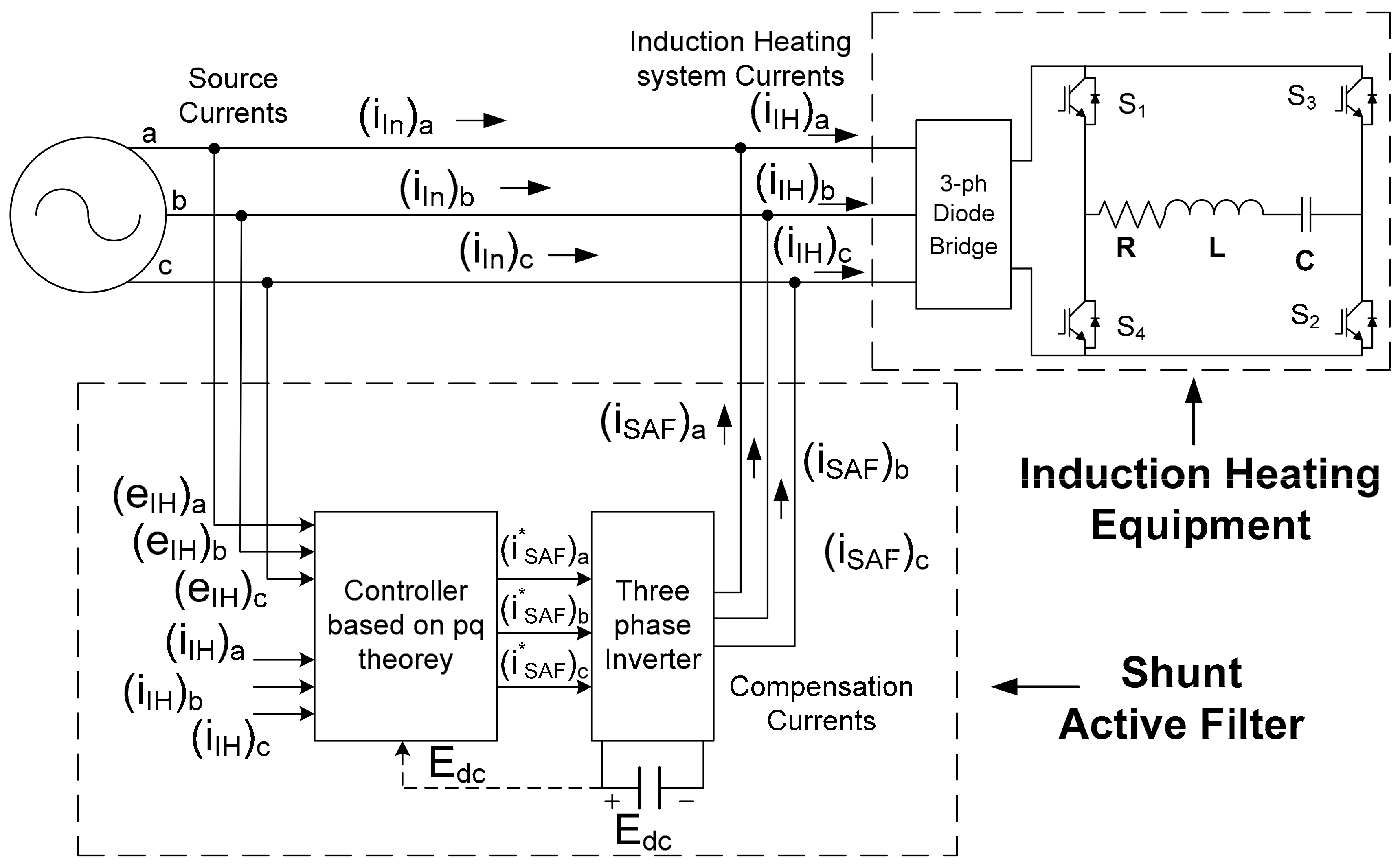
3. Proposed Structure of IH Equipment with SAF
Figure 1 shows the basic structure of the IH equipment with the application of a SAF at the input side. It also shows a controller based on instantaneous power theory that is used to control the compensation currents produced by the SAF. A high-frequency alternating magnetic field is produced by the series resonant inverter that cuts the workpiece and produces a heating effect due to the eddy current loss and hysteresis loss. The latter occurs mainly because of the continuous magnetization and demagnetization of the workpiece by the alternating magnetic field. One more factor that greatly governs the heating phenomenon is the skin effect, due to which the current is mainly confined in the outer surface of the workpiece and thus produces more heat there.
The instantaneous power theory that was introduced by Akagi was used for determining the harmonic distortions [
30,
31].
According to the notations used in
Figure 1:
where (
IIH1)
a, (
IIH1)
b, and (
IIH1)
c represent, respectively, the root mean square values of the fundamental component of currents (
iIH)
a, (
iIH)
b, and (
iIH)
c, that are flowing in the IH System. The high-frequency harmonics generated because of the power electronic switches are given by the quantities
The various quantities may be represented as follows:
Now, using the Clarke transformation, the three-phase quantities that are in the
a-
b-
c coordinate system can be converted to the α-β-0 coordinate system:
where:
Similarly, the three phase currents that are flowing in the induction heating system can be converted from the
a-
b-
c coordinate system to the α-β-0 coordinate system as follows:
The three-phase instantaneous real power can be expressed in the
a-
b-
c coordinate system as well as in the α-β-0 coordinate system as follows:
The two components of
pαβ0 are the instantaneous real power (
pIH) and the instantaneous zero sequence power (
p0).
Because of the absence of the neutral wire in the three-phase system, the zero sequence components (eIH, iIH, and p0) can be assumed to be missing.
The instantaneous imaginary power can also be expressed in the α-β coordinate system as follows:
The above expressions may be written in matrix form as follows:
Since the instantaneous active and reactive powers constitute components that are associated with both the fundamental and harmonic components of voltages and currents, they can be represented as follows:
where:
represents the fundamental component of instantaneous active power. It corresponds to the real power that is absorbed by the induction heating equipment, and it is associated with the fundamental components of current iIH and voltage eIH;
represents the harmonic component of instantaneous active power. It corresponds to the real power that is absorbed by the induction heating equipment, and it is associated with the harmonic components of current iIH and voltage eIH;
represents the fundamental component of instantaneous reactive power, and it is associated with the fundamental components of current iIH and voltage eIH;
represents the harmonic component of instantaneous reactive power, and it is associated with the harmonic components of current iIH and voltage eIH.
We will now consider a new quantity,
iIHF, that represents the fundamental active component of the current absorbed by the induction heating equipment. It can be expressed in the α-β coordinate system in the form of a matrix as follows:
Using the above expressions, the reference current (
) can be obtained in the α-β coordinate system as follows:
Putting the values of Equations (22) and (27) in Equation (29), we get:
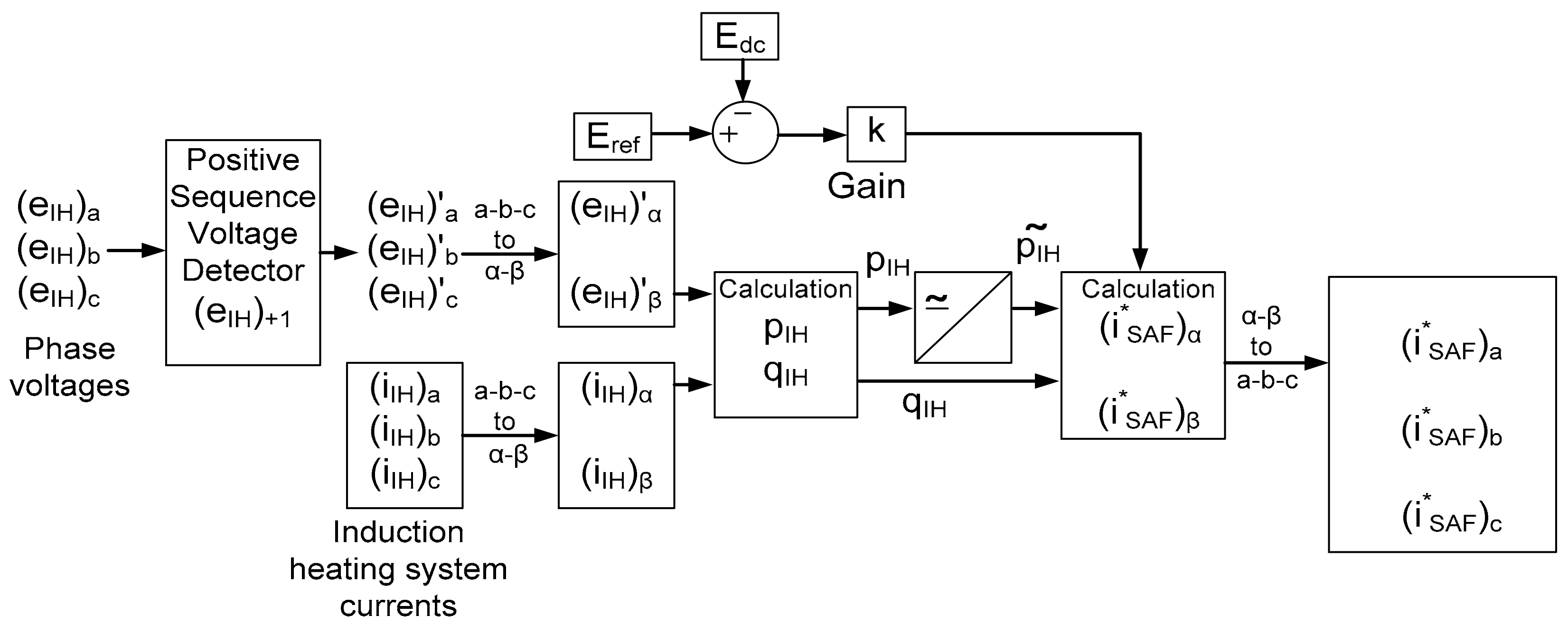
One of the most important components of the shunt active filter (SAF) is the inverter. It has a capacitor whose voltage corresponds to the DC link voltage (
Edc). This voltage needs to be regulated to keep it within appropriate levels. This process is compulsory for the proper functioning of the SAF. The voltage (
Edc) of the DC link increases when the SAF receives the energy that is stored in the capacitor. If it does not receive energy, the capacitor will discharge, and thus there is a reduction in
Edc. A regulating power (
Pregulating) which is a function of the reference voltage (
Eref) and the DC link voltage (
Edc) is used to regulate the value of the instantaneous active power.
where
k is a constant.
Thus, considering the regulation of the voltage (
Edc) of the DC link and using the above expressions, the reference currents can be expressed as follows:
The reference currents that are in the α-β coordinate system can be converted back to the
a-
b-
c coordinate system as follows:
4. The Case of Unbalanced and Non-Sinusoidal Input Voltage
The phase voltages (e
IH)
a, (e
IH)
b, and (e
IH)
c at the input of the IH equipment might be balanced or unbalanced. The former mainly contains positive sequence component (e
IH)
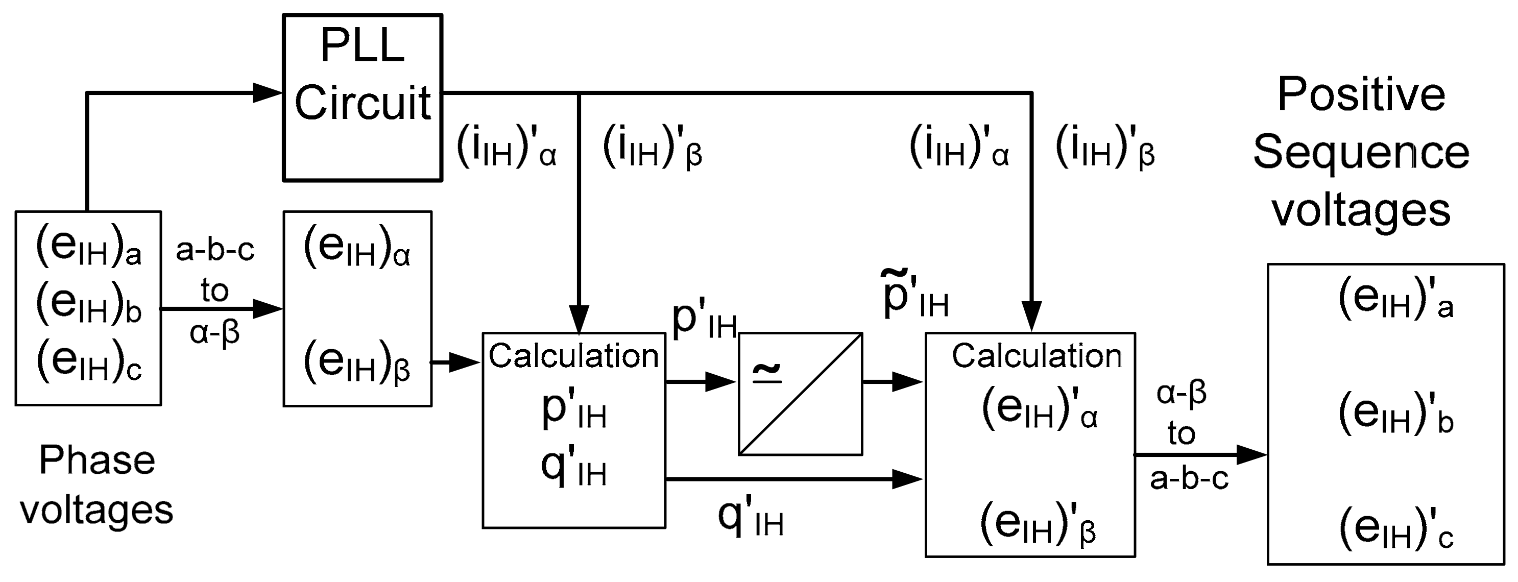
+1 while the latter also contains negative and zero sequence components at the fundamental frequency. Moreover, the harmonics from any sequence components are also present in the latter case (IEEE Working Group on Non-sinusoidal Situations, 1996). Thus, a positive sequence voltage detector (PSVD) needs to be employed to detect the fundamental positive sequence components of the input phase voltages (e
IH)
a, (e
IH)
b, and (e
IH)
c. The controller for the IH equipment based on instantaneous power theory shown in
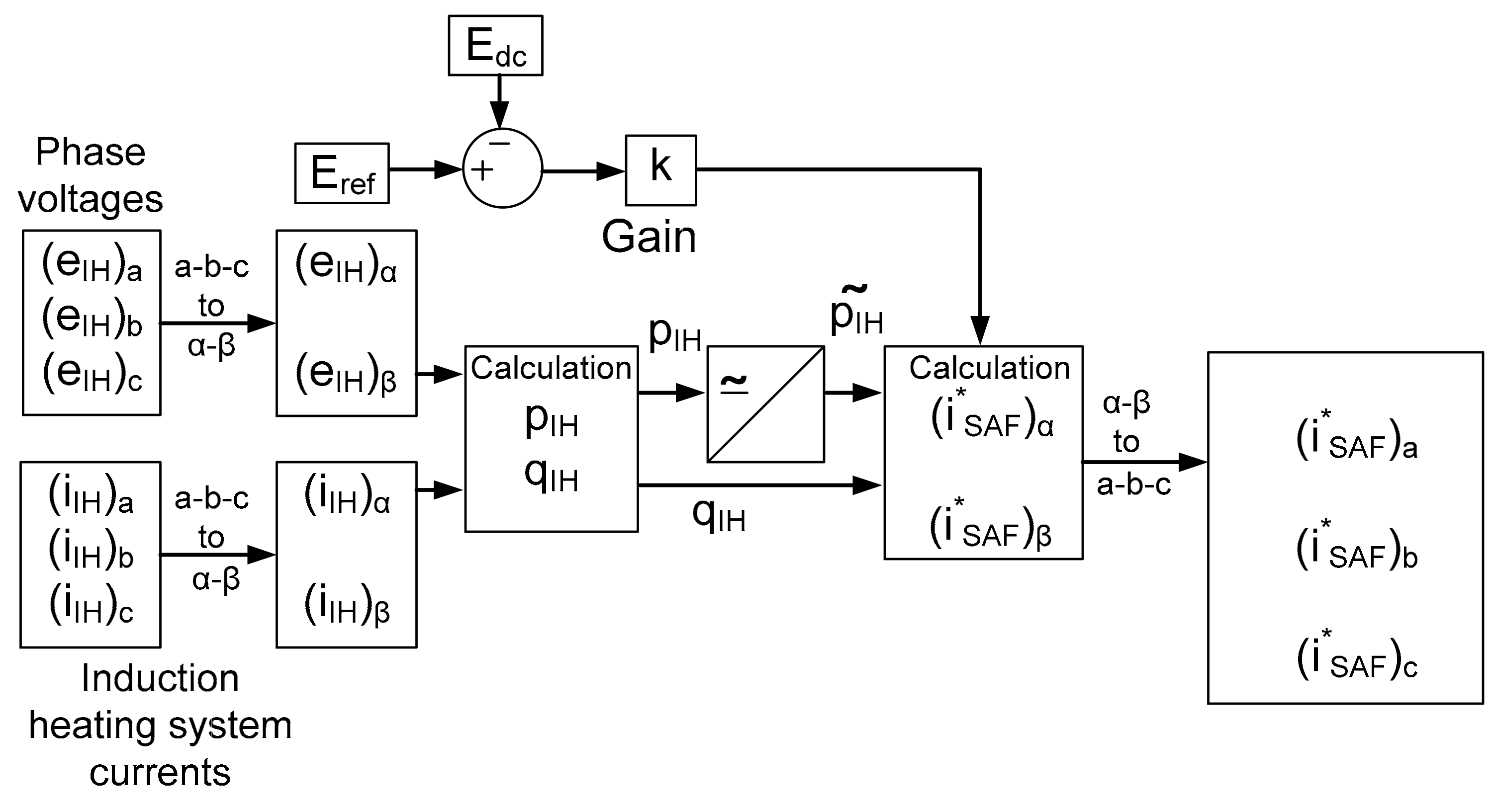
Figure 2 was upgraded by adding a PSVD block to enable it work in unbalanced and non-sinusoidal voltage conditions.
The PSVD block instantaneously extracts the fundamental positive sequence voltages (e
IH)
a, (e
IH)
b, and (e
IH)
c. Thus, the SAF compensates for the input current of the IH equipment in such a manner that only the active part of the fundamental positive sequence current (
iIH)
+1 is supplied by the power supply. The working of the PSVD, which consists of a phase-locked loop (PLL)circuit, is also very closely related to the PQ theory. The basic structure of the PSVD is shown in
Figure 3. The input phase voltages that are in the
a-
b-
c coordinate system can be transformed into the α-β coordinate system to get (e
IH)
α and (e
IH)
β. The PLL circuit produces auxiliary currents (
iIH)′
α and (
iIH)′
β, which have arbitrary magnitudes and are derived only from the positive sequence current (
IIH)
+1 at the fundamental frequency. These voltages and currents are used to compute the real and imaginary auxiliary powers
p′
IH and
q′
IH, respectively.
The IH system currents in the α-β coordinate system can be expressed in terms of symmetrical components as follows:
Considering the case of the fundamental (
m = 1) positive sequence component, Equations (37) and (38) can be expressed as follows:
Since, the amplitudes of auxiliary currents (
iIH)′
α and (
iIH)′
β are randomly selected, they may be considered as a unity to reduce the complexity. Moreover, the phase angles (θ
+1) of the aforesaid currents are also randomly selected, and thus they are taken as zero for simplicity. The only crucial aspect is the accurate determination of the fundamental frequency (ω
1) by the PLL circuit.
The average parts of auxiliary powers
p′
IH and
q′
IH are obtained only from the fundamental component of the positive sequence voltage (e
IH)
+1. The auxiliary currents (
iIH)′
α and (
iIH)′
β are also obtained only from (
iIH)
+1. Moreover, because of the fundamental component of the negative sequence voltage and the other voltage components, the harmonics are present only in the oscillating component of the auxiliary power that is not included in the inverse voltage calculation. The instantaneous voltages (e
IH)′
α and (e
IH)′
β, which represent the fundamental components of the positive sequence voltage, reobtained as follows:
Using Equations (41) and (42), the sum of the square of the auxiliary currents (
iIH)′
α and (
iIH)′
β can be calculated.
The positive sequence phase voltages (e
IH)′
a, (e
IH)′
b, and (e
IH)′
c can be obtained from (e
IH)′
α and (e
IH)′
β by using the inverse Clarke transformation as follows:
6. Simulation Diagram and Results
In the present work, the simulation of a high-frequency full-bridge series resonant inverter has been carried outby considering the equivalent circuit parameters. PSIM 2022.1, which is quite famous in the field of power electronics and motor drives, was used for the simulation of various equivalent circuits. First, an IH system with an SAFwas proposed as shown in
Figure 1, and the mathematical model of the controller was developed.
Figure 2 gives the proposed structure of the controller based on instantaneous power theory.
Figure 3 shows the proposed structure of a PSVD that was incorporated to help deal with the unbalanced input voltage conditions.
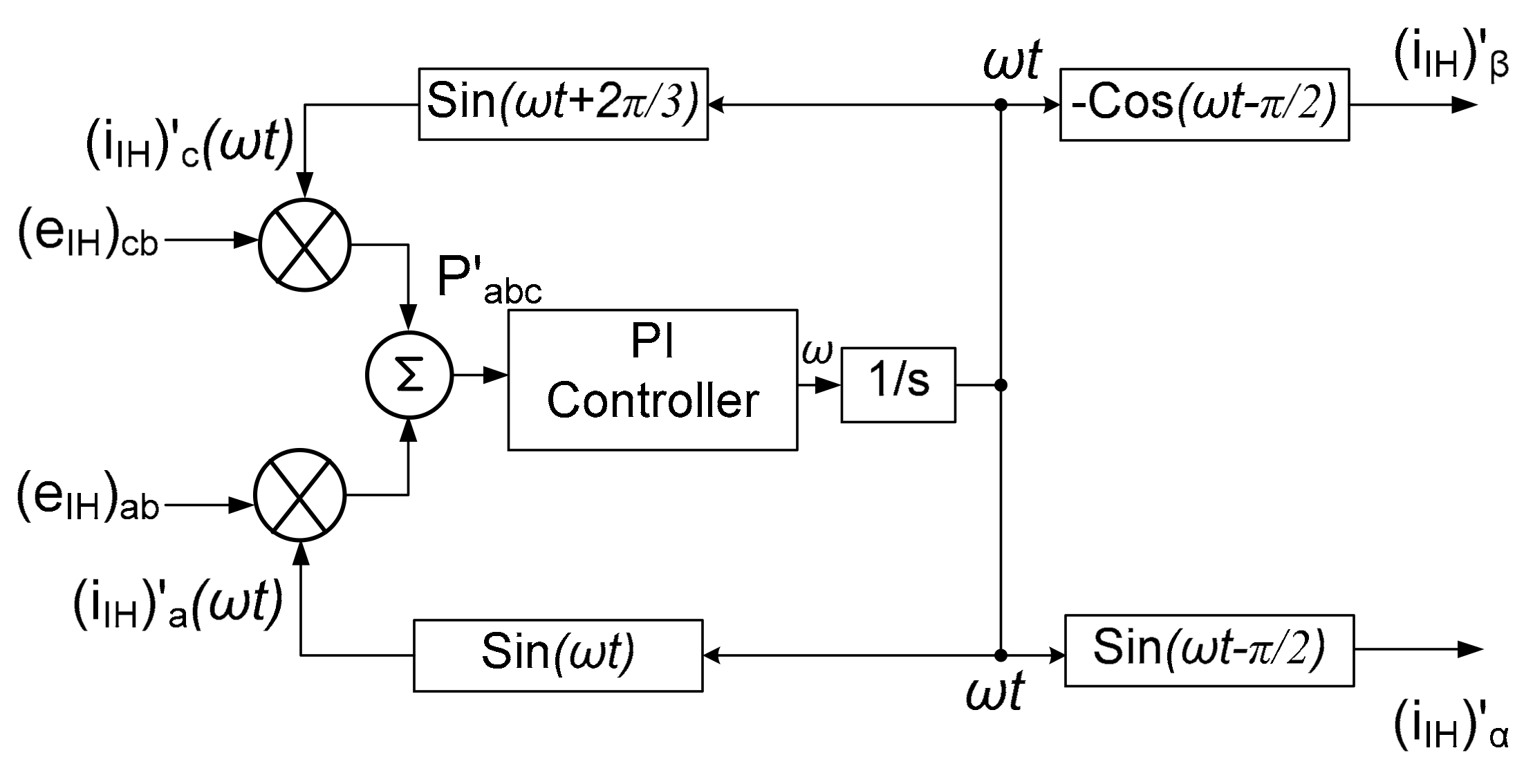
Figure 4 shows the block diagram of the PLL circuit which was used in
Figure 3. Finally, all these modifications were added to the structure outlined in
Figure 2, which was based on the original instantaneous power theory.
Figure 5 shows the proposed structure of a controller based on the extended instantaneous power theory which is capable of working even in unbalanced and non-sinusoidal input voltage conditions. Next, the simulations were performed to verify the necessity and importance of the SAF in the IH equipment. Initially, simulations were carried out without the application of a low pass filter (LPF), but subsequently they were carried out with a shunt active filter (SAF)installed at the input of the IH equipment.
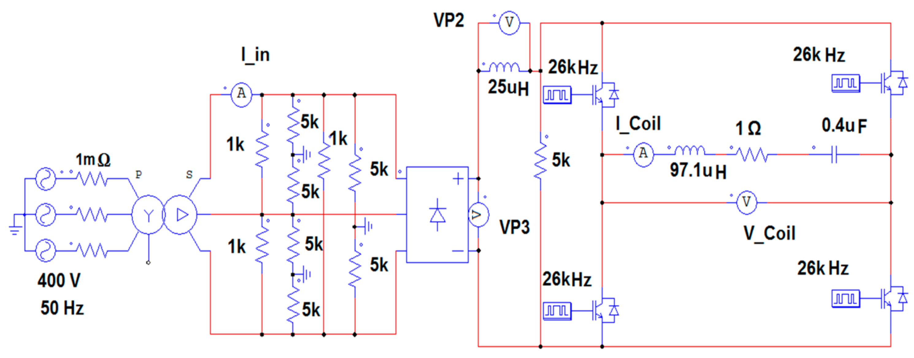
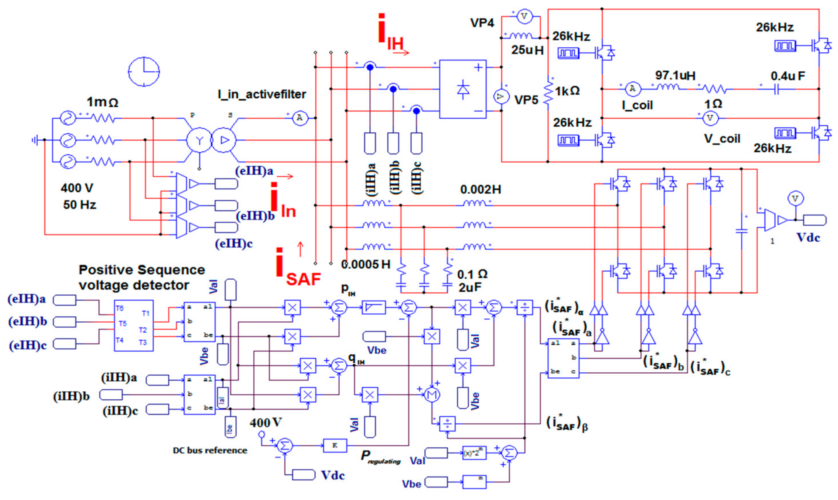
These were finally compared to see the effect of the SAF on the harmonics present in the input current waveform. The equivalent simulation circuit diagrams of the induction heating equipment without a filter and with an SAF are shown in
Figure 6 and
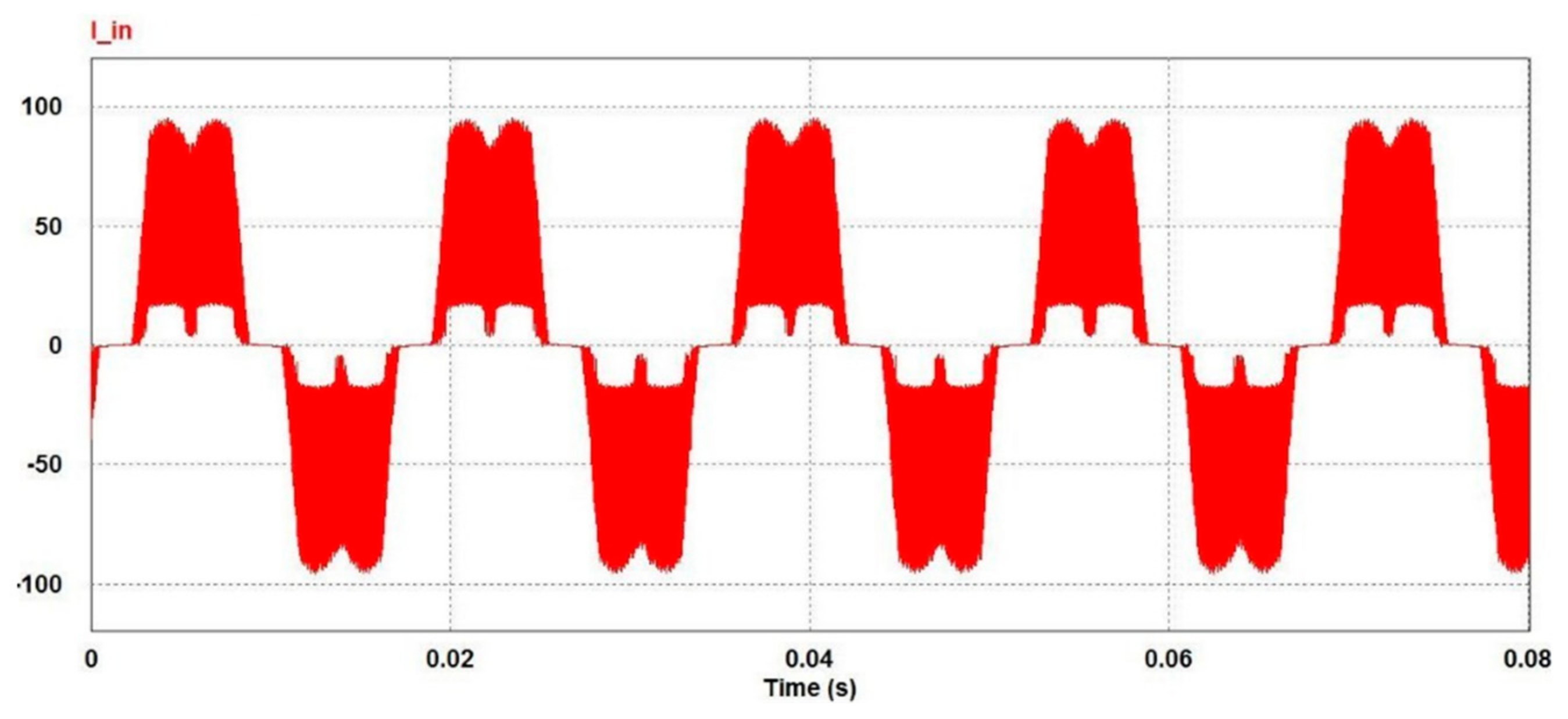
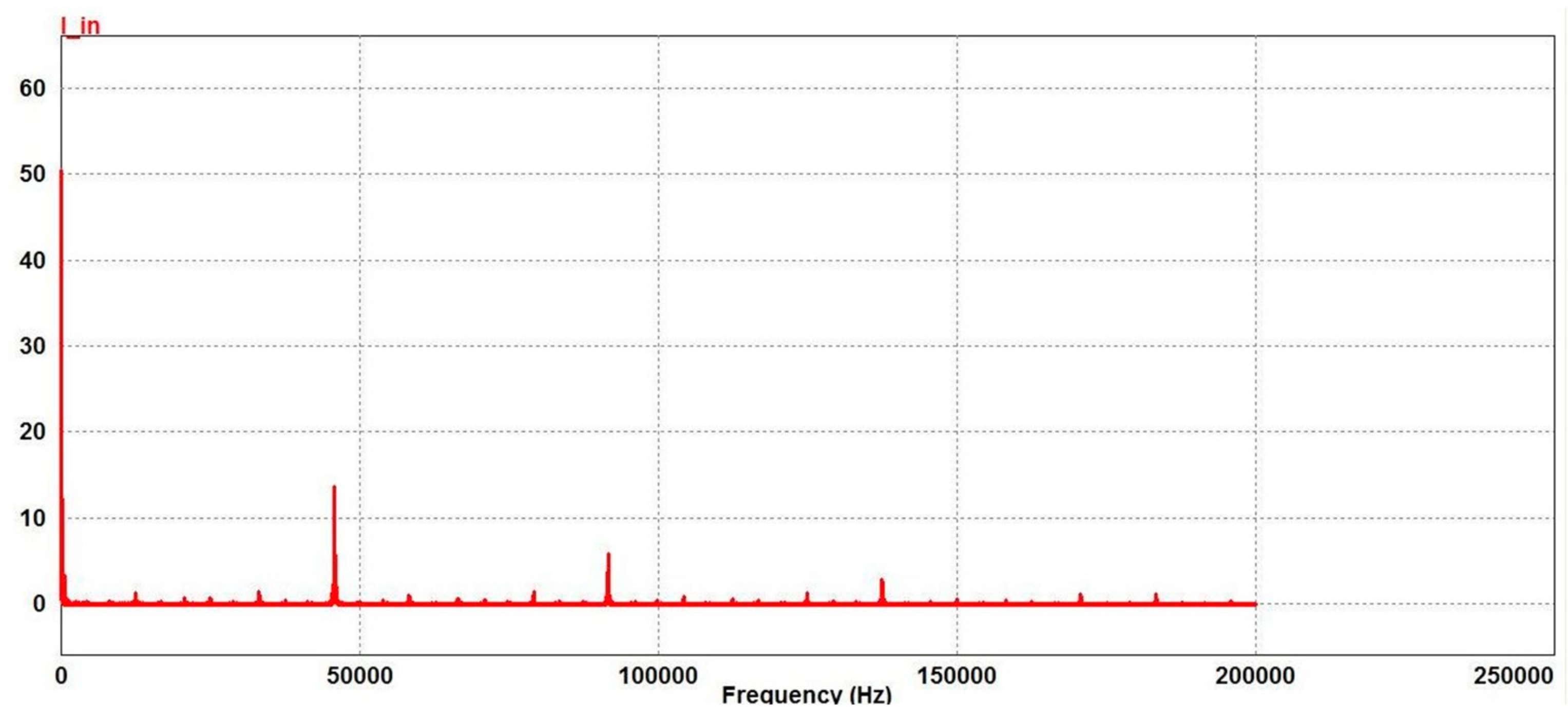
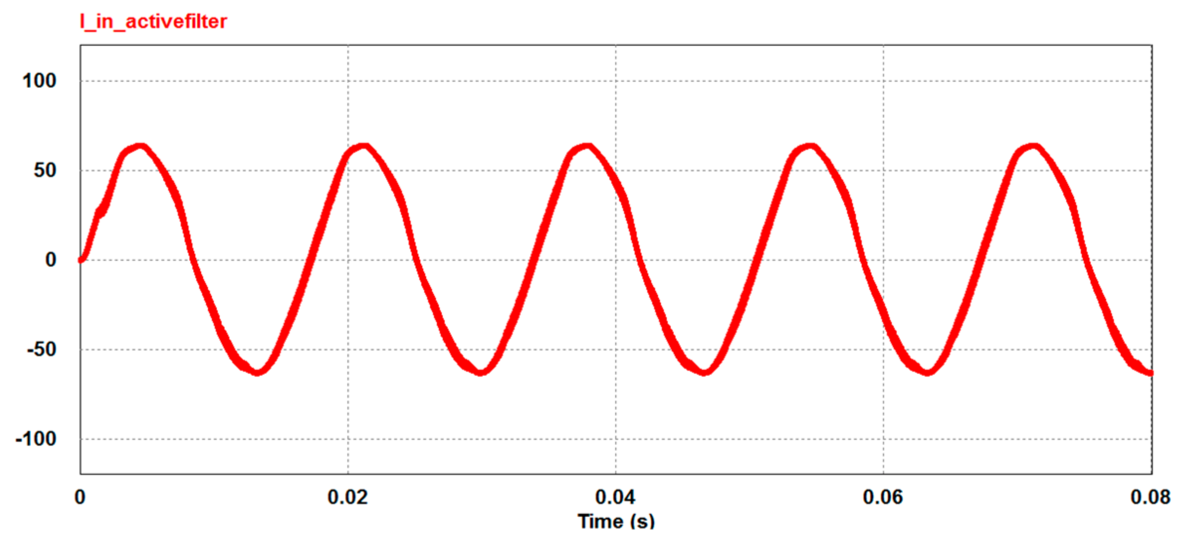
Figure 7, respectively. The corresponding waveforms of the input current obtained after a simulation in PSIM are also shown in
Figure 8 and
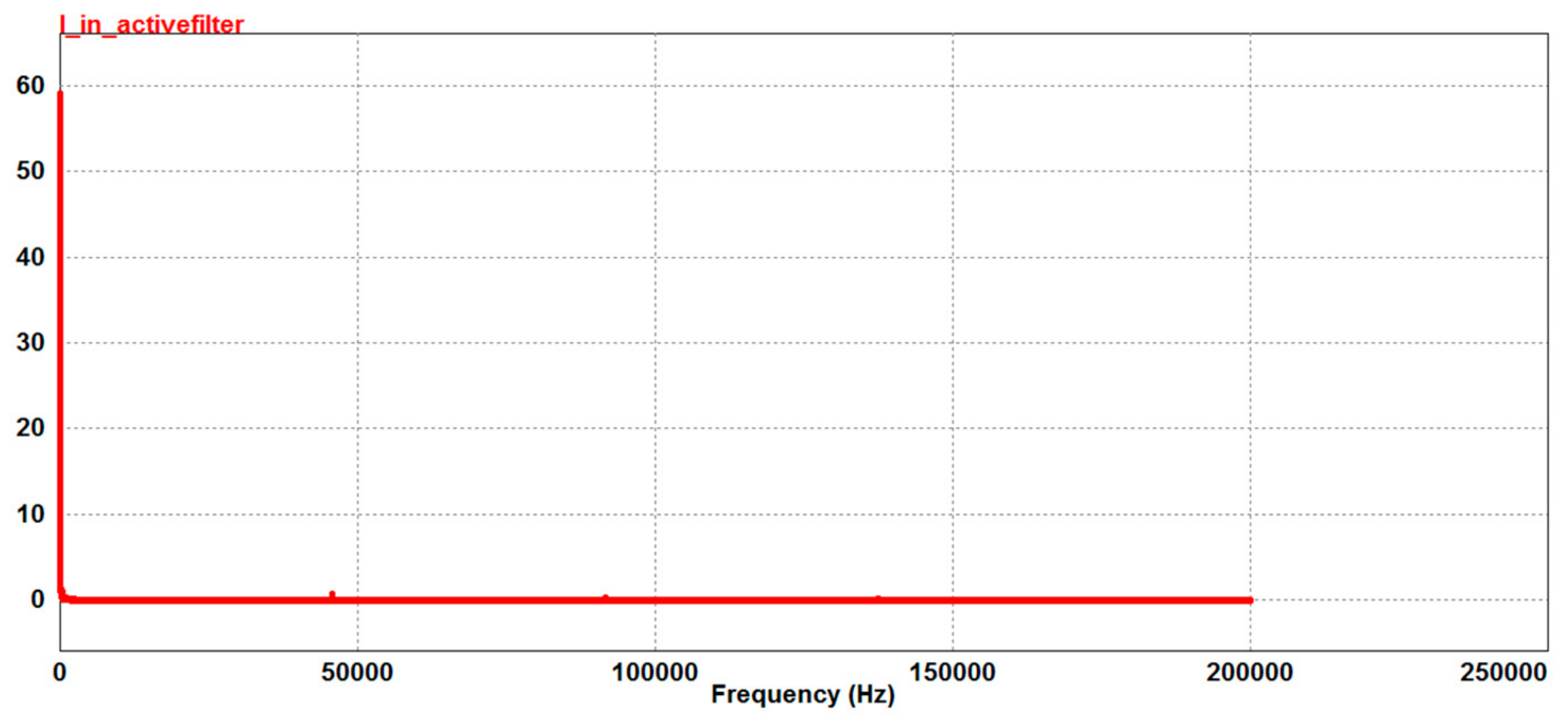
Figure 9, respectively. The FFT analysis of these waveforms is shown in
Figure 10 and
Figure 11, respectively. The equivalent simulation circuit diagram, which represents the basic structure of the IH equipment, consists of a three-phase sinusoidal AC source followed by a three-phase star-delta transformer that is fed to a three-phase uncontrolled bridge rectifier.
The output of the rectifier acts as an input to a high-frequency series resonant full-bridge inverter. The modeling of the IH coil was carried out with a combination of an inductor and a resistor in series connection with an external capacitor. The series combination of the RLC acts as a load to the high-frequency inverter, which is resonant in nature. Along with these essential components, a few more components, such as voltmeters and ammeters, were used for measurement purposes.
8. Conclusions and Future Work
In the present paper, an IPT-based shunt active filter for harmonic mitigation in an induction heating system has been proposed. Moreover, an exhaustive analysis of its performance under unbalanced and non-sinusoidal input voltage conditions, as well as dynamic conditions with changing reference currents, has been carried out. The modified version of the IPT caters to the specific needs of IH systems for industrial use. The control strategy followed in the proposed method compensated for the harmonic currents and reactive power of the IH system, and the DC bus voltage of the SAF was almost maintained at the reference value under all conditions. A detailed mathematical analysis of the proposed model was carried out, followed by its validation via simulations in PSIM. The FFT analysis of the input phase current waveform shows that almost all the high-frequency harmonic components were attenuated with the application of an SAF. Its THD was found to be 30.92% without a filter, while the THD with an SAF was just 1.34%. The results show that the developed model could reduce the THD to a level of less than 5%, which is in accordance with IEEE 519-1992 and IEEE 519-2014 standards. This would also be considerably less than the previous models proposed in the literature.
In order to validate the simulation results, it will be necessary to set up the shunt active filter based IH system hardware in future work. Its practical implementation and its measurements will be realized using a dSPACE DS1104 R&D controller with TMS320F240 as a slave DSP. Moreover, its ability to provide harmonic mitigation, reactive power compensation, and the balancing of unbalanced and non-linear loads will be under consideration. Experimental results will be compared with the simulation results to determine the efficacy and viability of the proposed method.

 ,
, 


