
Investigations on the Modulation Strategies for Performance Improvement of a Controlled Wind Energy System
 ,
, 
Abstract
:1. Introduction
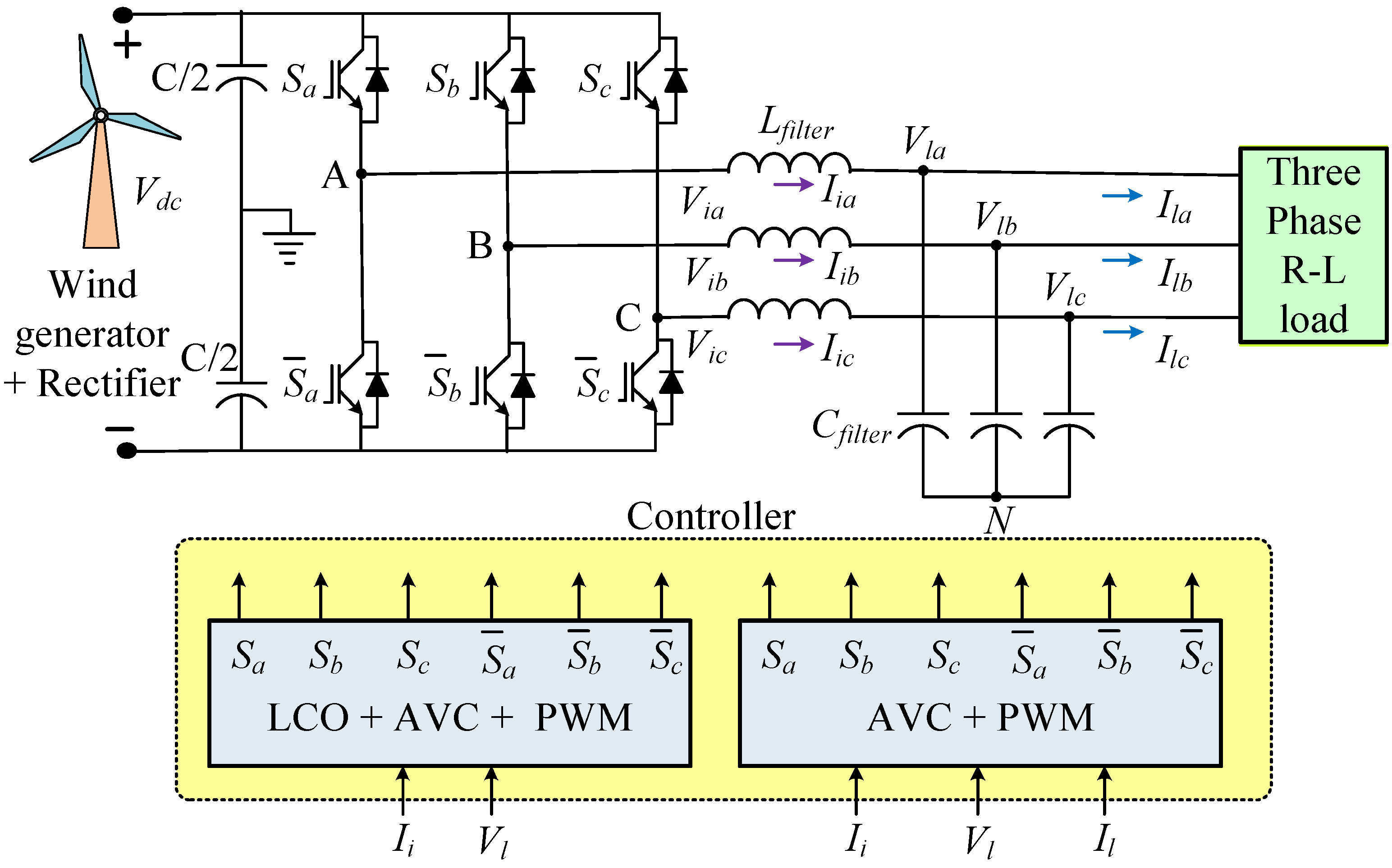
2. Mathematical Model of the System
3. Detailed Description and Design of Controllers
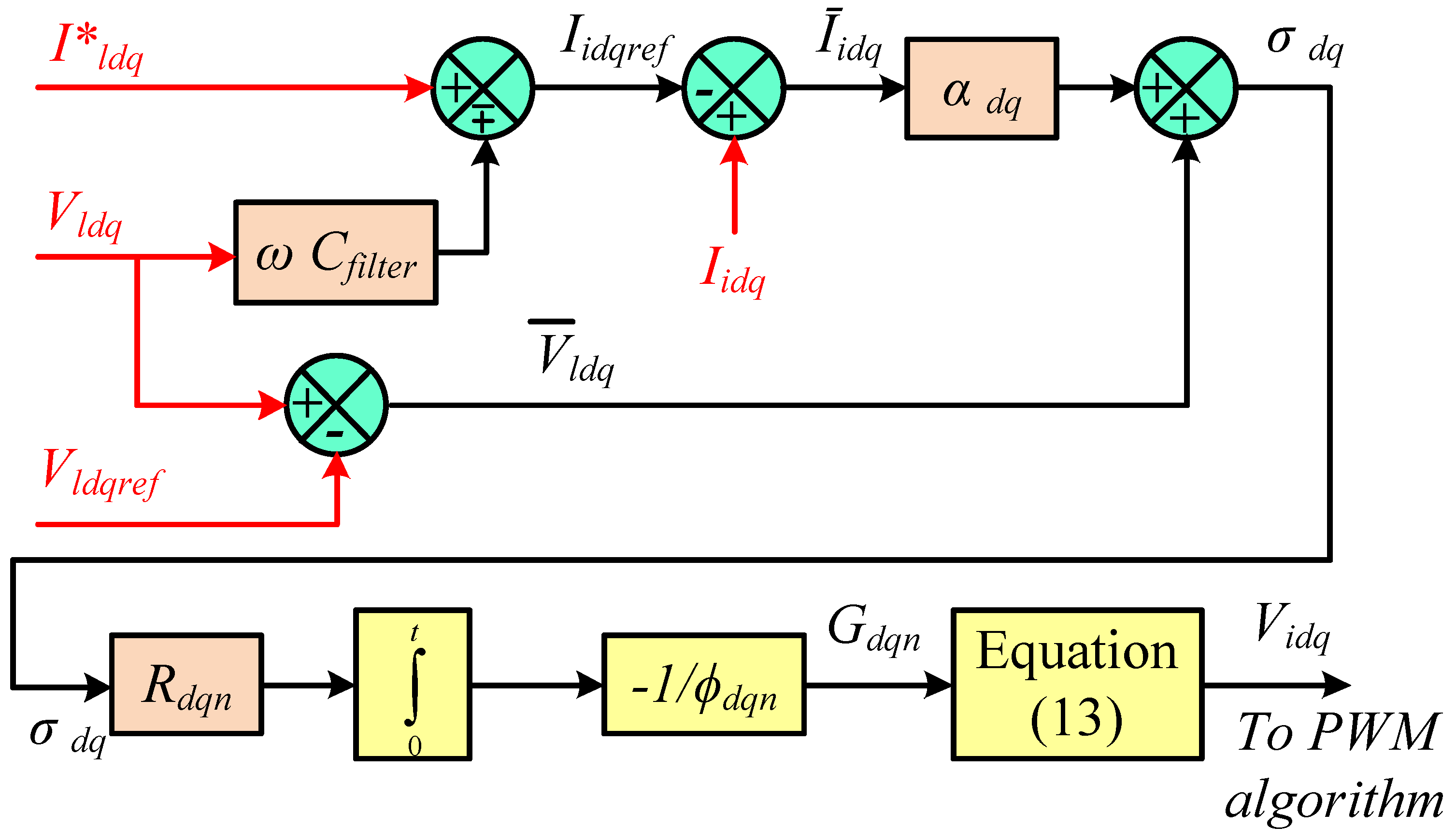
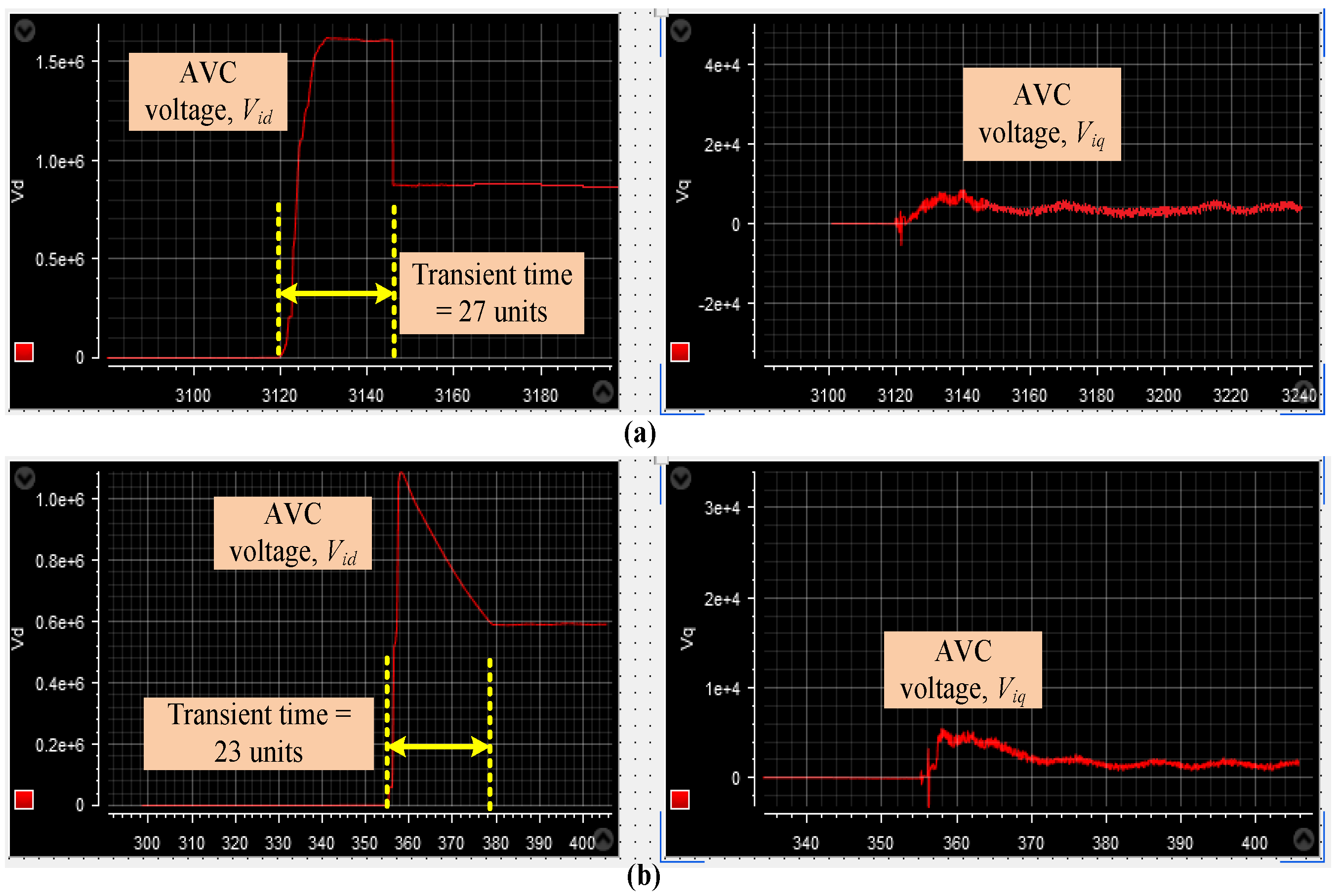
3.1. Adaptive Voltage Controller
3.2. Load Current Observer
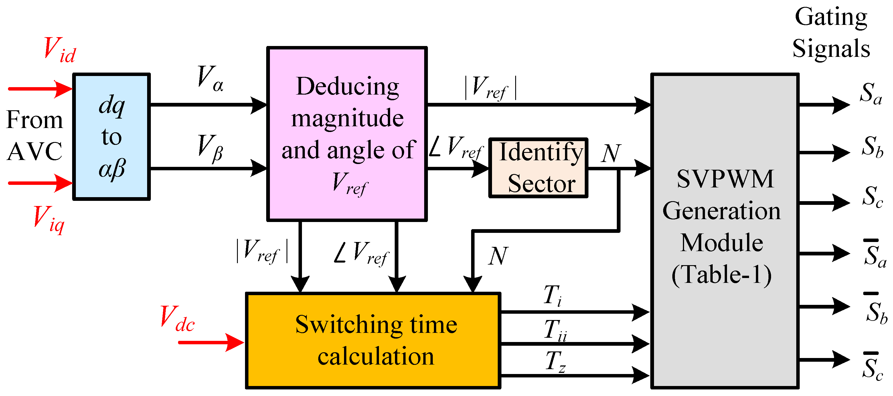
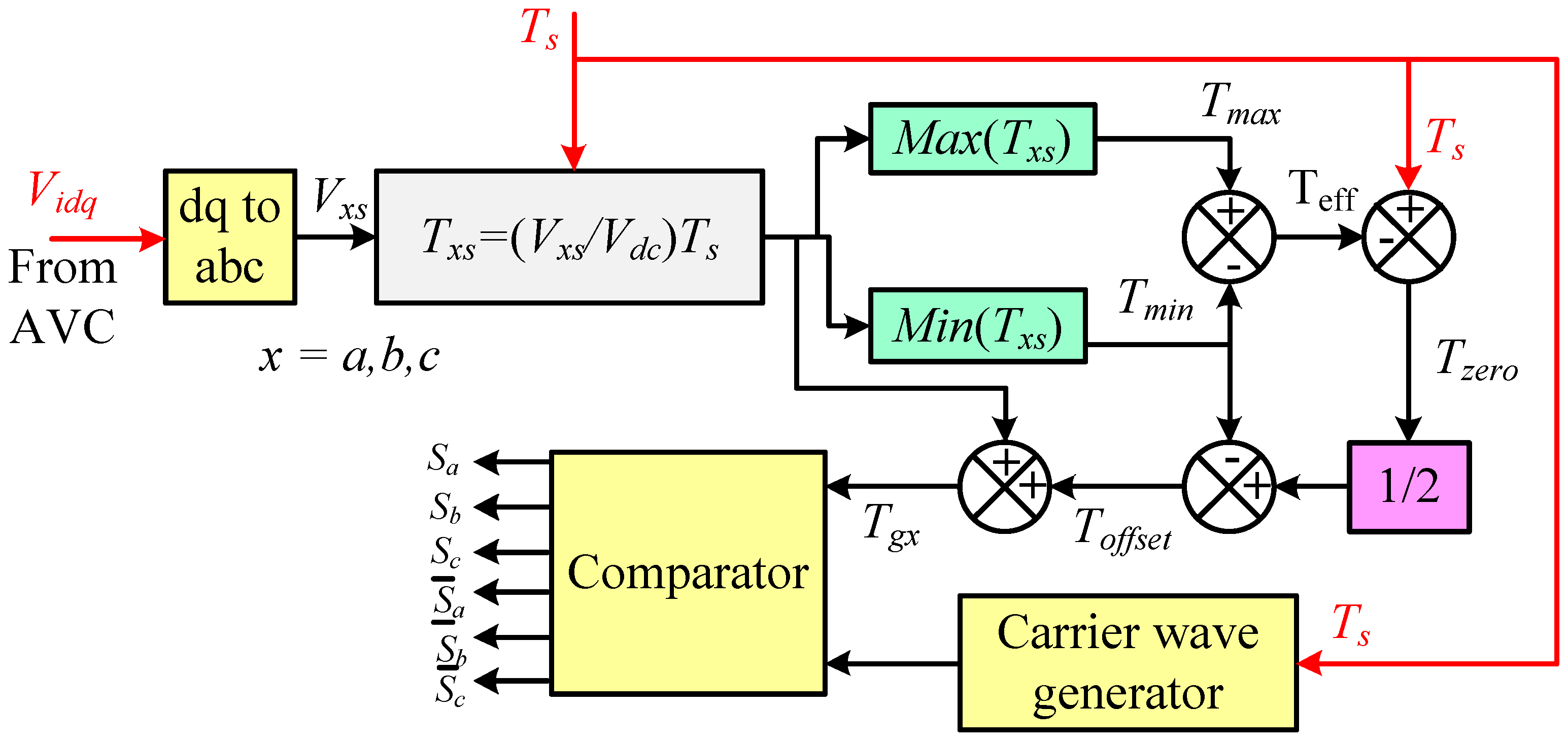
3.3. Pulse Width Modulation Techniques
3.3.1. Conventional Space Vector PWM
3.3.2. Unified Voltage Space Vector PWM
4. Simulation Studies
- Case-I:
- AVC + Conventional SVPWM
- Case-II:
- LCO + AVC + Conventional SVPWM
- Case-III:
- AVC + UVSVPWM
- Case-IV:
- LCO + AVC + UVSVPWM
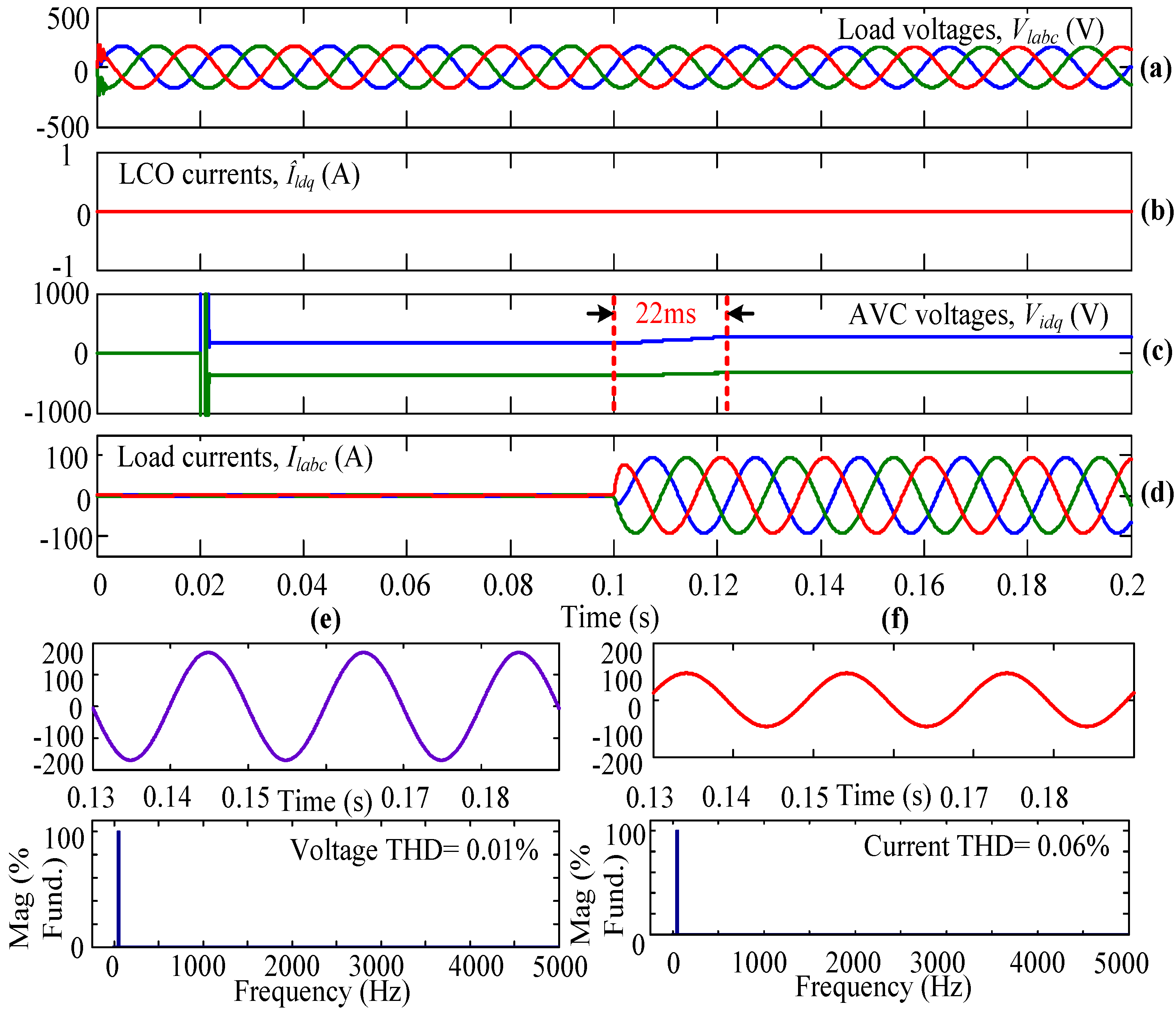
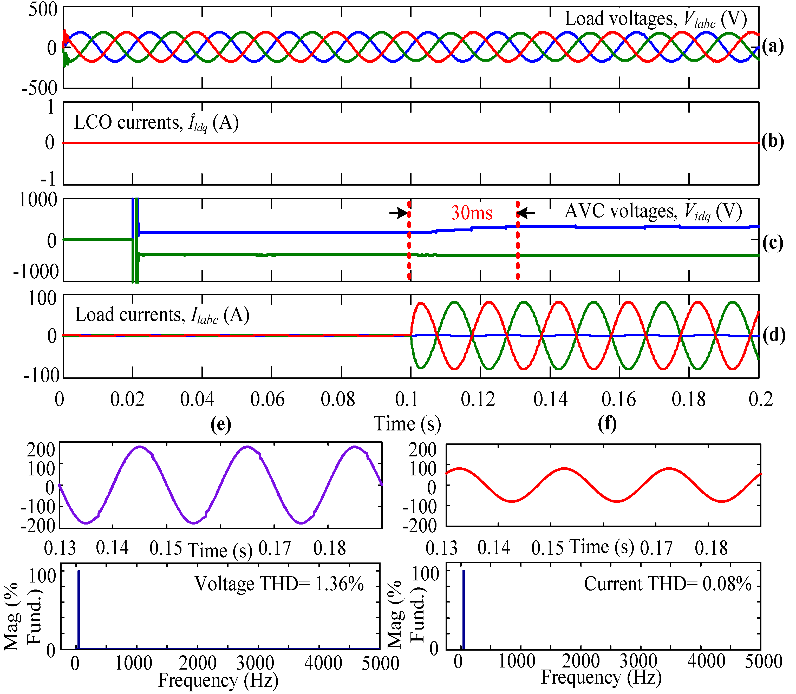
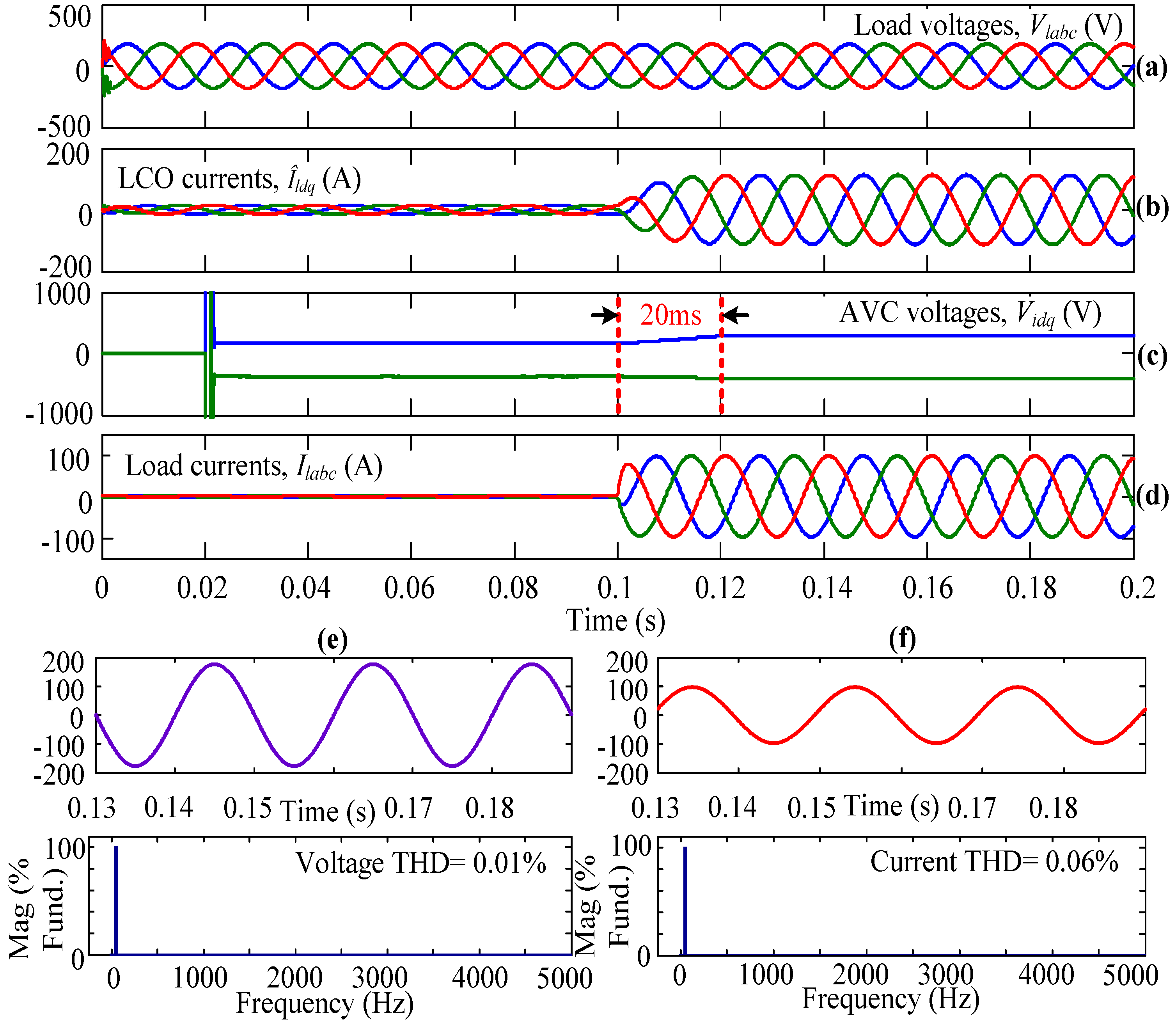
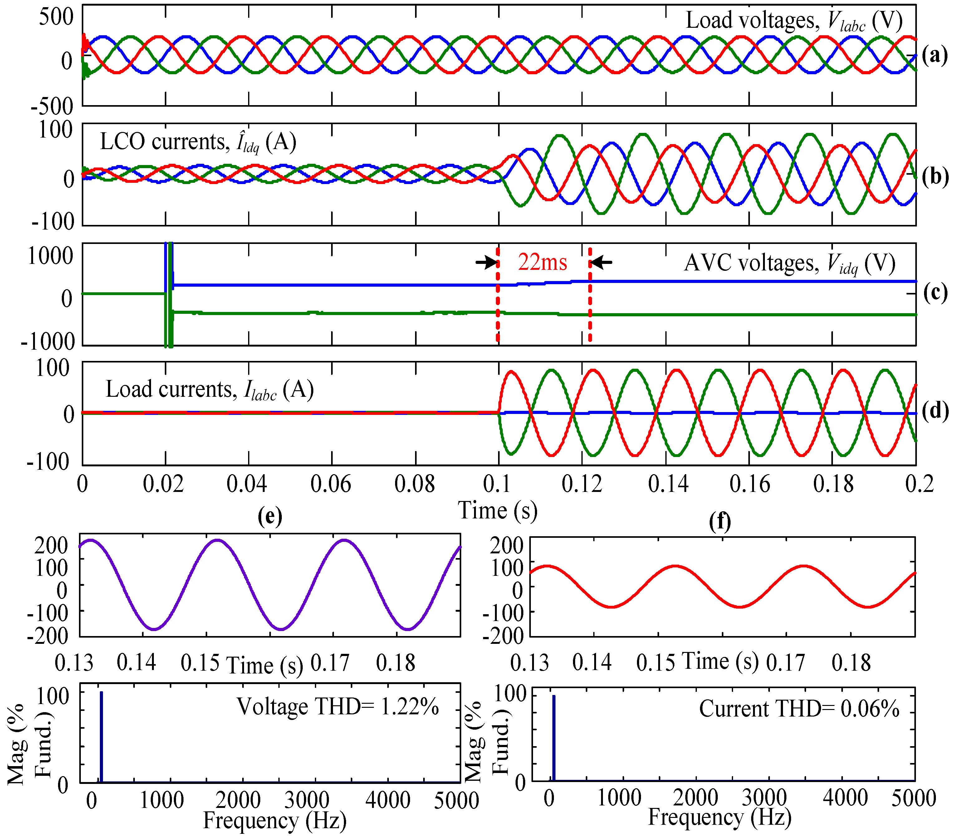
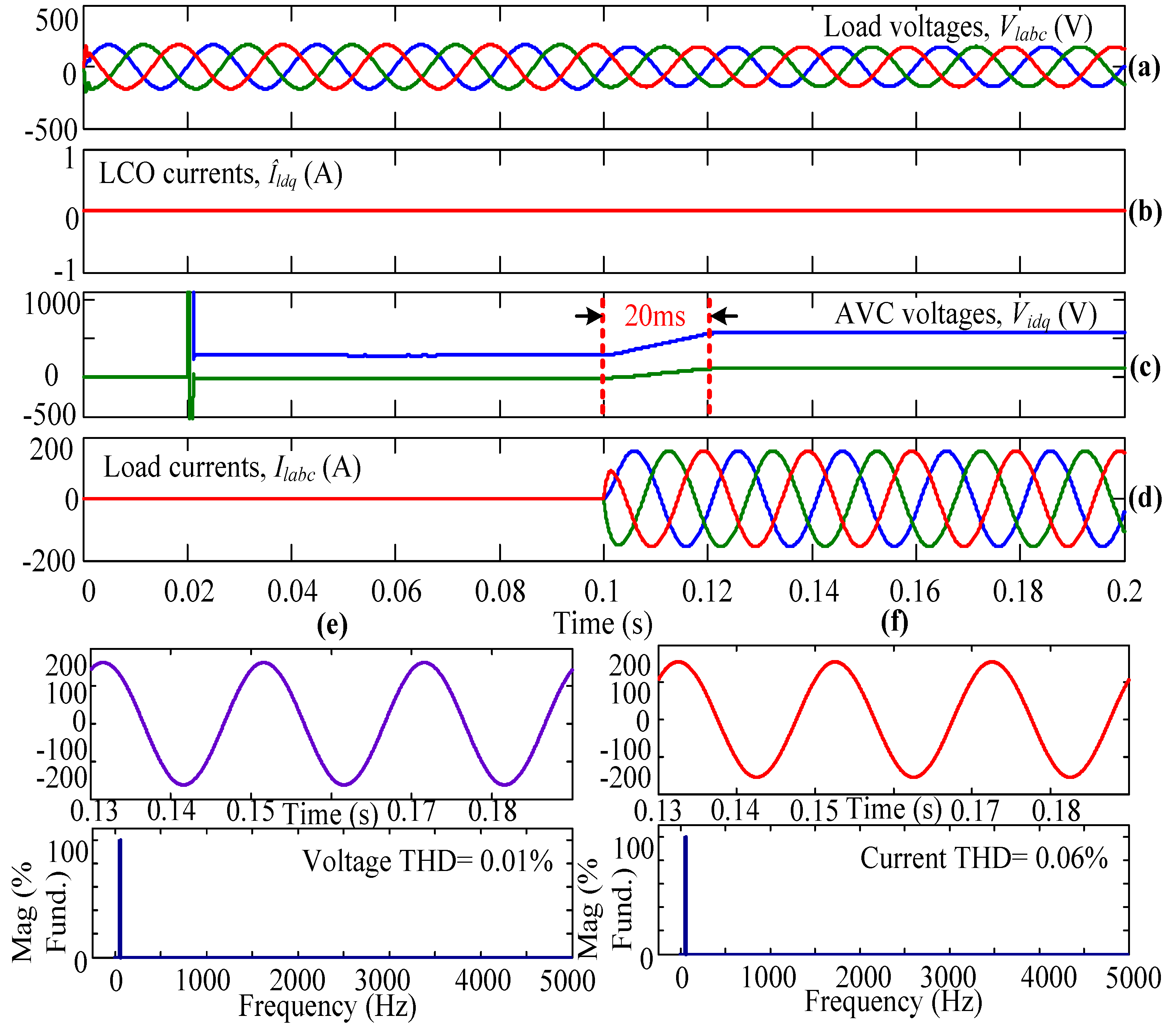
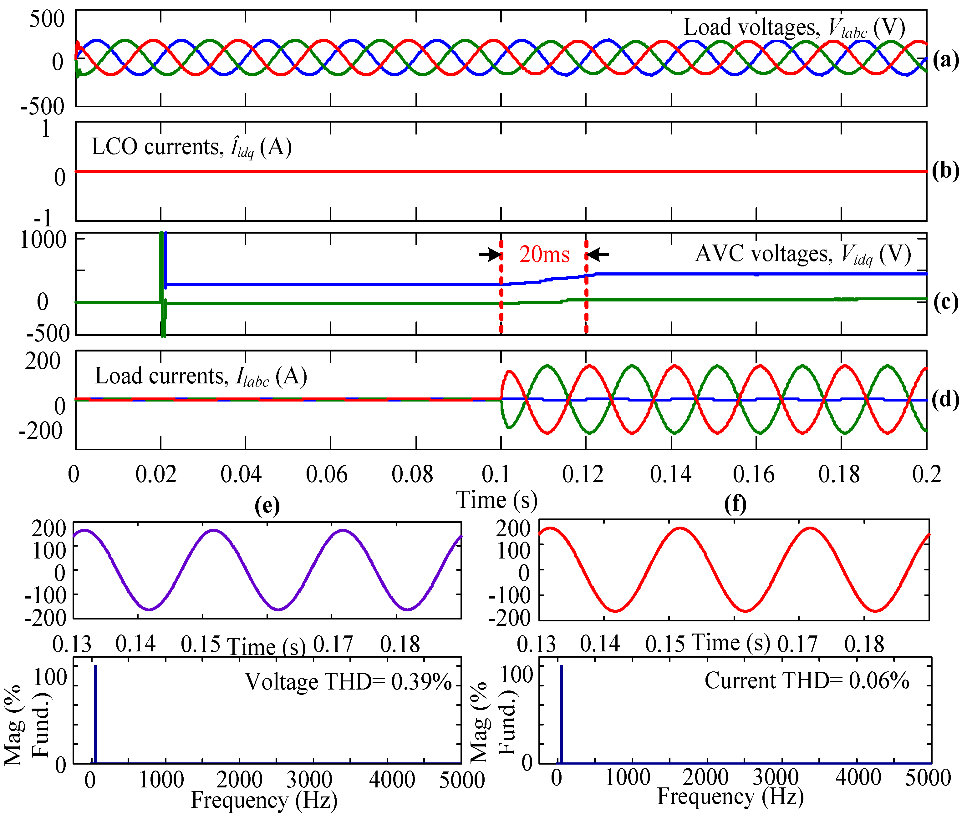
4.1. Case-I
4.2. Case-II
4.3. Case-III
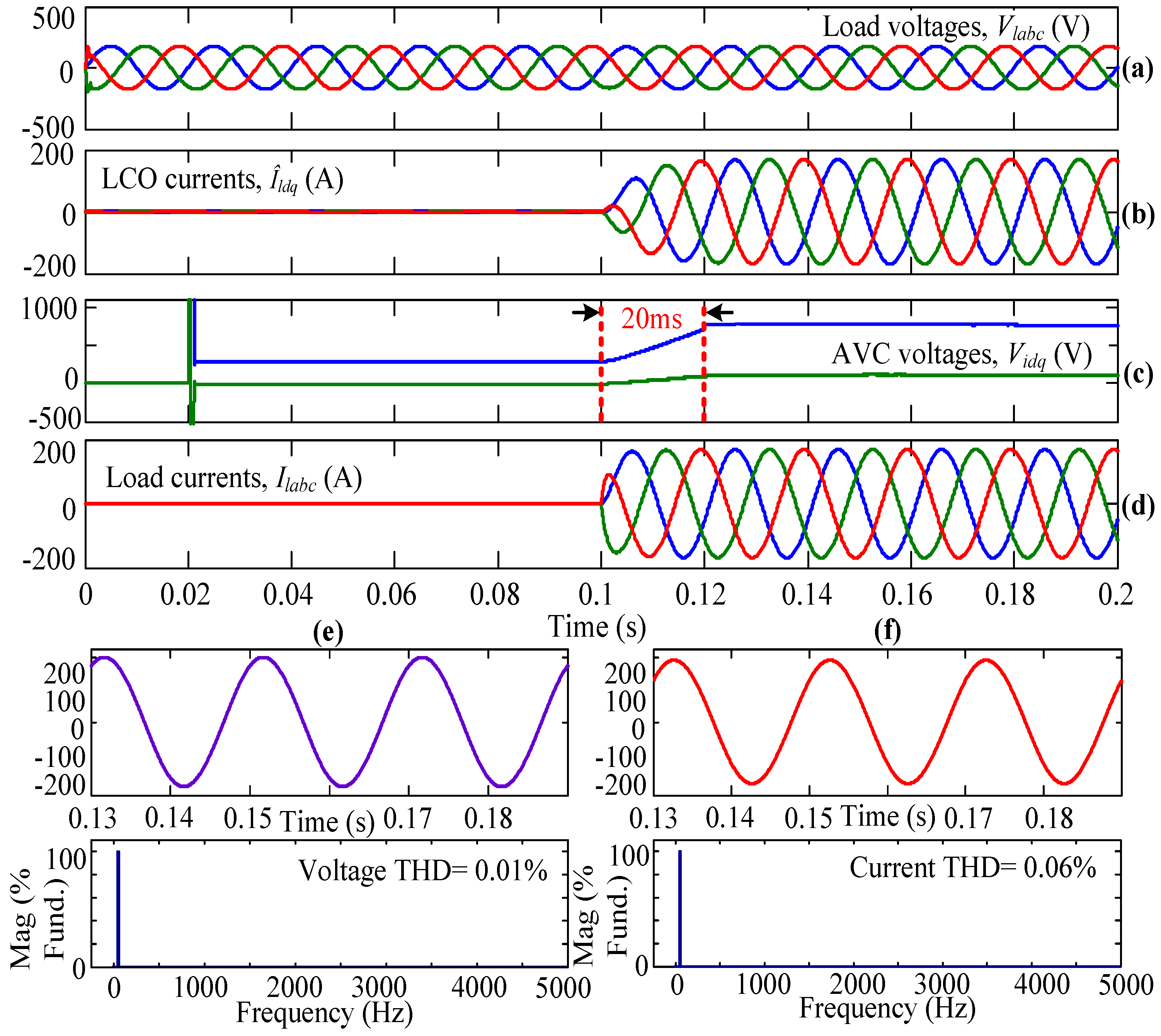
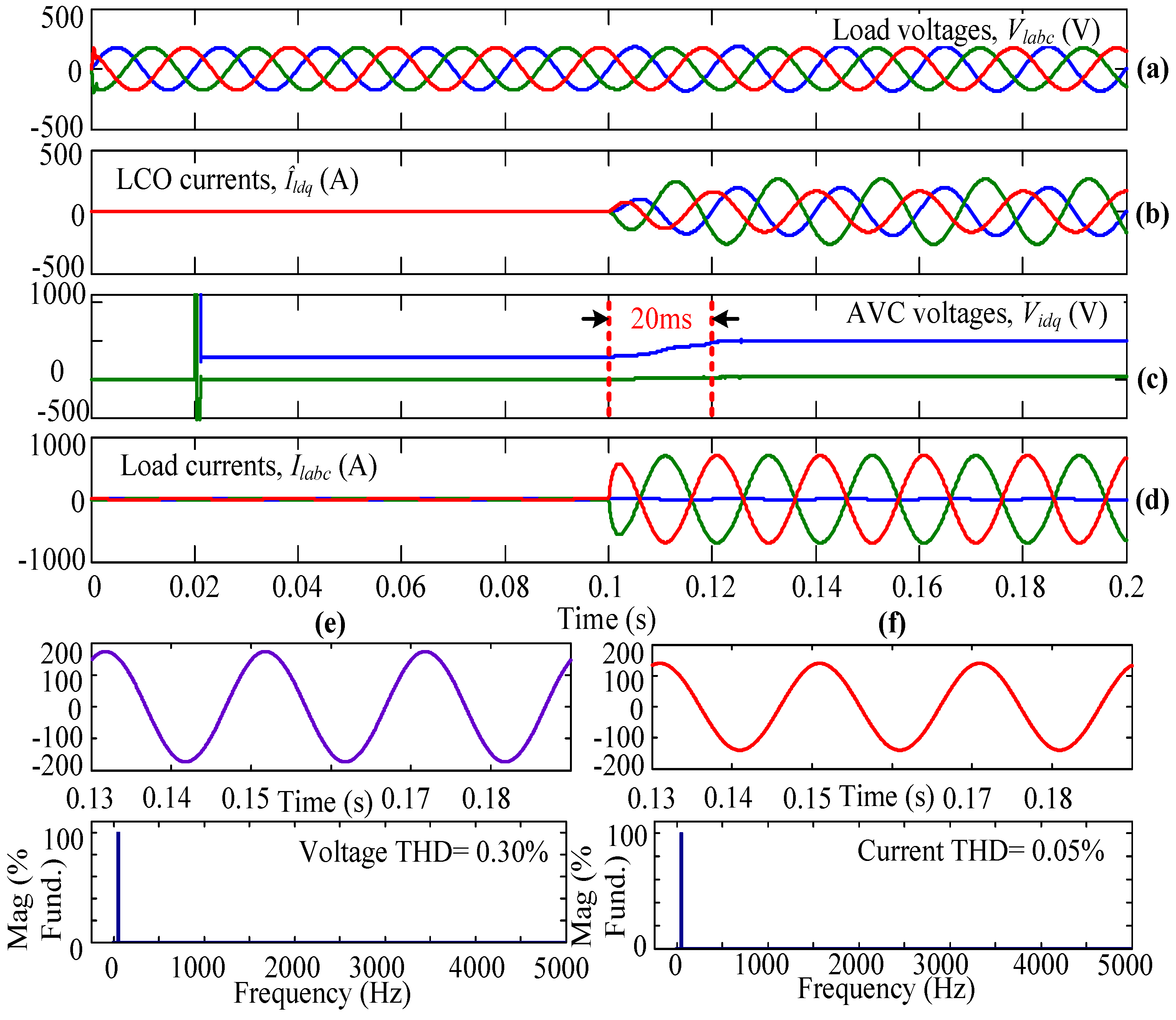
4.4. Case-IV
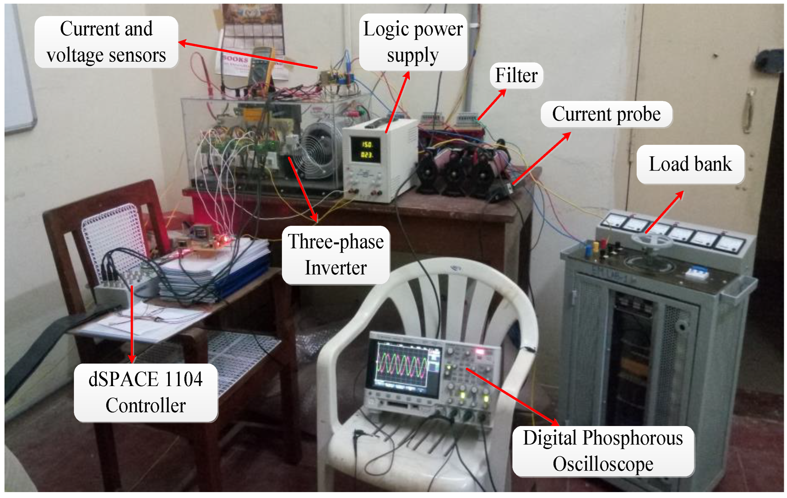
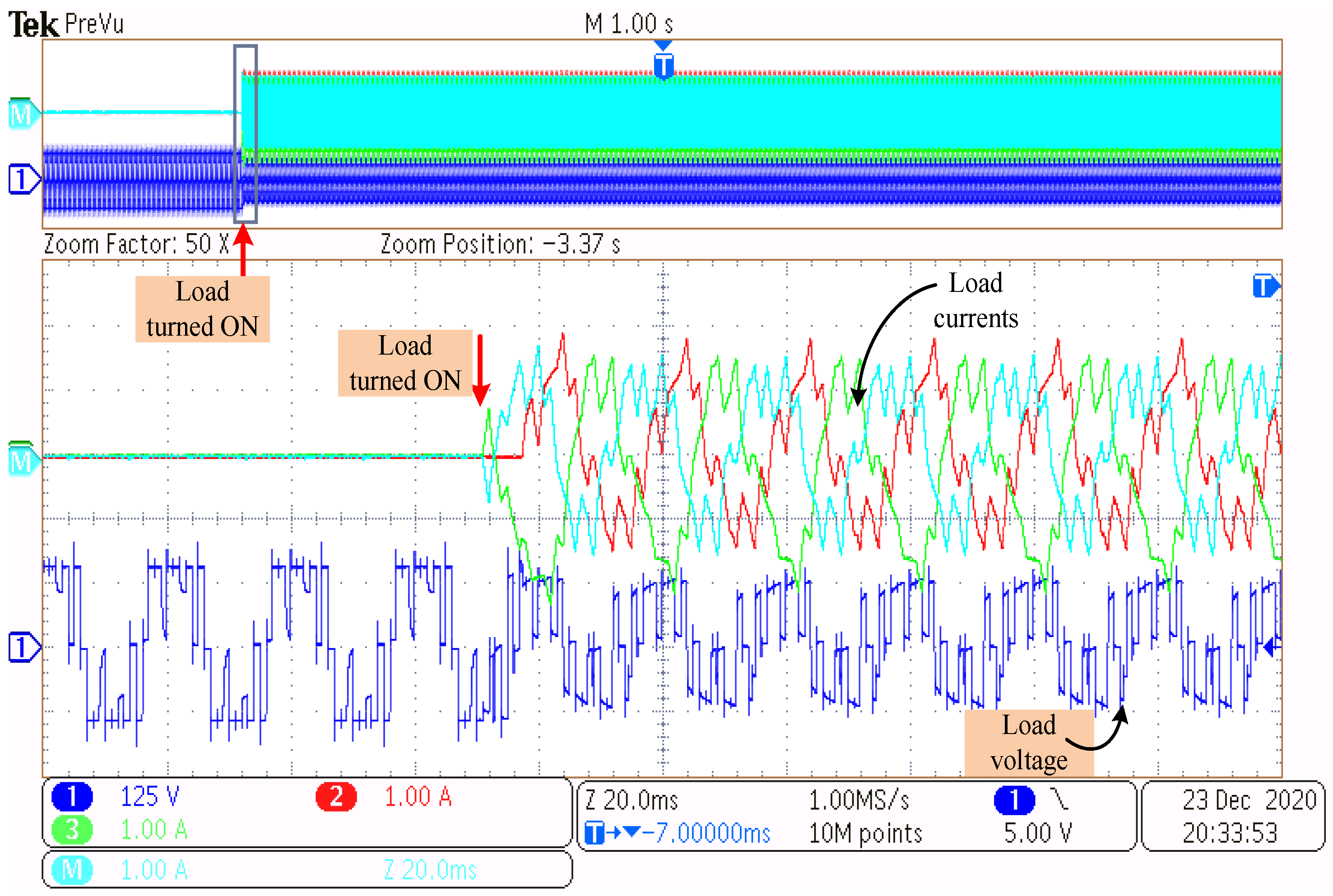
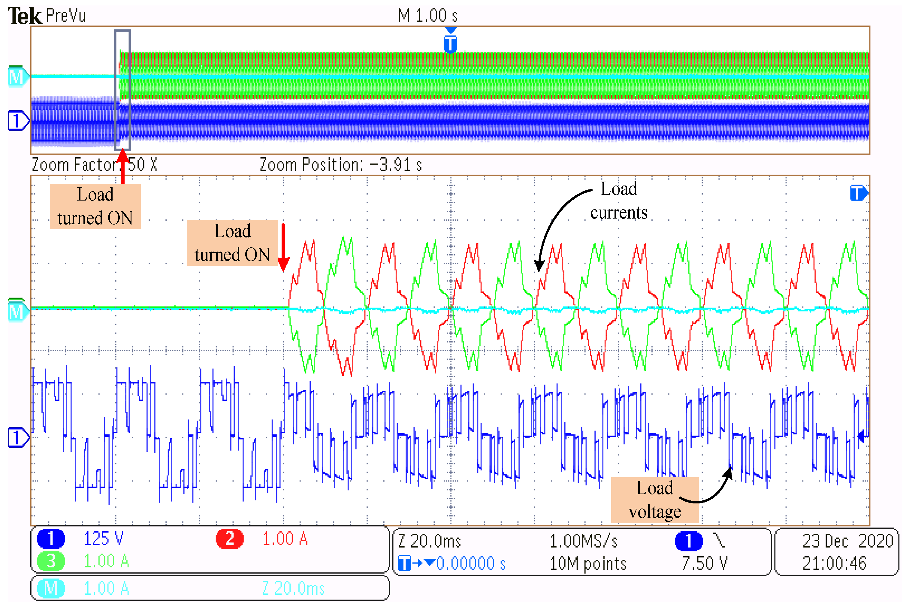
5. Experimental Studies
6. Conclusions
Author Contributions
Funding
Data Availability Statement
Acknowledgments
Conflicts of Interest
References
- Tawfiq, K.B.; Mansour, A.; Ibrahim, M.N.F.; Elkholy, E.; Sergeant, P. Implementation of matrix converter in wind energy conversion system with modified control techniques. Electr. Power Compon. Syst. 2019, 47, 1316–1331. [Google Scholar] [CrossRef]
- Chinthamalla, R.; Karampuri, R.; Jain, S.; Sanjeevikumar, P.; Blaabjerg, F. Dual Solar Photovoltaic Fed Three-Phase Open-End Winding Induction Motor Drive for Water Pumping System Application. Electr. Power Components Syst. 2018, 46, 1896–1911. [Google Scholar] [CrossRef]
- Djilali, L.; Sanchez, E.N.; Belkheiri, M. First and High Order Sliding Mode Control of a DFIG-Based Wind Turbine. Electr. Power Components Syst. 2020, 48, 105–116. [Google Scholar] [CrossRef]
- Krishnamurthy, K.; Padmanaban, S.; Blaabjerg, F.; Neelakandan, R.B.; Prabhu, K.R. Power Electronic Converter Configurations Integration with Hybrid Energy Sources—A Comprehensive Review for State-of the-Art in Research. Electr. Power Components Syst. 2020, 47, 1623–1650. [Google Scholar] [CrossRef]
- Jha, S.K.; Kumar, D. Demand Side Management for Stand-Alone Microgrid Using Coordinated Control of Battery Energy Storage System and Hybrid Renewable Energy Sources. Electr. Power Components Syst. 2019, 47, 1261–1273. [Google Scholar] [CrossRef]
- Ibrahim, A.M.; Attia, M.A.; Abdelaziz, A.Y. A DSM Approach for Distribution Systems with High Wind Power Penetration. Electr. Power Components Syst. 2020, 48, 56–69. [Google Scholar] [CrossRef]
- Tu, C.-S.; Hong, C.-M.; Lu, K.-H. Design of Novel Intelligent Controller for Doubly-Fed Induction Generator-Driven Wind Turbine to Improve Transient Control Performance. Electr. Power Components Syst. 2020, 48, 174–185. [Google Scholar] [CrossRef]
- Irfan, M.; Chandrashekhar, M.; Sushama, M. Coordinated Control of Distributed Generators and Compensator in a Micro Grid. Int. J. Recent Technol. Eng. 2019, 8, 2057–2063. [Google Scholar]
- Ganguly, S.; Shiva, C.K.; Mukherjee, V. Frequency stabilization of isolated and grid connected hybrid power system models. J. Energy Storage 2018, 19, 145–159. [Google Scholar] [CrossRef]
- Marwali, M.; Keyhani, A. Control of Distributed Generation Systems—Part I: Voltages and Currents Control. IEEE Trans. Power Electron. 2004, 19, 1541–1550. [Google Scholar] [CrossRef]
- Dai, M.; Marwali, M.N.; Jung, J.-W.; Keyhani, A. A Three-Phase Four-Wire Inverter Control Technique for a Single Distributed Generation Unit in Island Mode. IEEE Trans. Power Electron. 2008, 23, 322–331. [Google Scholar] [CrossRef]
- Karimi, H.; Davison, E.J.; Iravani, R. Multivariable Servomechanism Controller for Autonomous Operation of a Distributed Generation Unit: Design and Performance Evaluation. IEEE Trans. Power Syst. 2010, 25, 853–865. [Google Scholar] [CrossRef]
- Karimi, H.; Yazdani, A.; Iravani, R. Robust Control of an Autonomous Four-Wire Electronically-Coupled Distributed Generation Unit. IEEE Trans. Power Deliv. 2011, 26, 455–466. [Google Scholar] [CrossRef]
- Deng, H.; Oruganti, R.; Srinivasan, D. Analysis and Design of Iterative Learning Control Strategies for UPS Inverters. IEEE Trans. Ind. Electron. 2007, 54, 1739–1751. [Google Scholar] [CrossRef]
- Yazdani, A. Control of an Islanded Distributed Energy Resource Unit with Load Compensating Feed-Forward. In Proceedings of the IEEE Power and Energy Society General Meeting—Conversion and Delivery of Electrical Energy in the 21st Century, Pittsburgh, PA, USA, 20–24 July 2008; pp. 1–7. [Google Scholar] [CrossRef]
- Cortes, P.; Ortiz, G.; Yuz, J.I.; Rodriguez, J.; Vazquez, S.; Franquelo, L.G. Model Predictive Control of an Inverter With Output LC Filter for UPS Applications. IEEE Trans. Ind. Electron. 2009, 56, 1875–1883. [Google Scholar] [CrossRef]
- Ahmed, K.H.; Massoud, A.M.; Finney, S.J.; Williams, B.W. A Modified Stationary Reference Frame-Based Predictive Current Control With Zero Steady-State Error for LCL Coupled Inverter-Based Distributed Generation Systems. IEEE Trans. Ind. Electron. 2011, 58, 1359–1370. [Google Scholar] [CrossRef]
- Escobar, G.; Stankovic, A.; Mattavelli, P. An Adaptive Controller in Stationary Reference Frame for D-Statcom in Unbalanced Operation. IEEE Trans. Ind. Electron. 2004, 51, 401–409. [Google Scholar] [CrossRef]
- Do, T.D.; Leu, V.Q.; Choi, Y.-S.; Choi, H.H.; Jung, J.-W. An Adaptive Voltage Control Strategy of Three-Phase Inverter for Stand-Alone Distributed Generation Systems. IEEE Trans. Ind. Electron. 2013, 60, 5660–5672. [Google Scholar] [CrossRef]
- Manias, S.N. 6—Inverters (DC–AC Converters). In Power Electronics and Motor Drive Systems; Academic Press: Cambridge, MA, USA, 2017; pp. 271–500. [Google Scholar] [CrossRef]
- Kim, J.-S.; Sul, S.-K. A Novel Voltage Modulation Technique of the Space Vector PWM. IEEJ Trans. Ind. Appl. 1996, 116, 820–825. [Google Scholar] [CrossRef]
- Karampuri, R.; Jain, S.; Somasekhar, V.T. Common-Mode Current Elimination PWM Strategy Along With Current Ripple Reduction for Open-Winding Five-Phase Induction Motor Drive. IEEE Trans. Power Electron. 2019, 34, 6659–6668. [Google Scholar] [CrossRef]
- Åström, K.J.; Wittenmark, B. Computer-Controlled Systems—Theory and Design; Prentice-Hall: Englewood Cliffs, NJ, USA, 1990. [Google Scholar]
- Durgam, R.; Karampuri, R. Modulation Technique to Improve the Performance of a Voltage Controlled Wind Energy Conversion System. In Proceedings of the 2022 Second International Conference on Power, Control and Computing Technologies (ICPC2T), Raipur, India, 1–3 March 2022; pp. 1–6. [Google Scholar] [CrossRef]
- Pande, J.; Nasikkar, P.; Kotecha, K.; Varadarajan, V. A Review of Maximum Power Point Tracking Algorithms for Wind Energy Conversion Systems. J. Mar. Sci. Eng. 2021, 9, 1187. [Google Scholar] [CrossRef]
- Majout, B.; El Alami, H.; Salime, H.; Zine Laabidine, N.; El Mourabit, Y.; Motahhir, S.; Bouderbala, M.; Karim, M.; Bossoufi, B. A Review on Popular Control Applications in Wind Energy Conversion System Based on Permanent Magnet Generator PMSG. Energies 2022, 15, 6238. [Google Scholar] [CrossRef]
- Bouderbala, M.; Bossoufi, B.; Lagrioui, A.; Taoussi, M.; Aroussi, H.A.; Ihedrane, Y. Direct and indirect vector control of a doubly fed induction generator based in a wind energy conversion system. Int. J. Electr. Comput. Eng. 2019, 9, 1531–1540. [Google Scholar] [CrossRef]
- Mahfoud, M.E.L.; Bossoufi, B.; Ouanjli, N.E.L.; Mahfoud, S.; Taoussi, M. Improved Direct Torque Control of Doubly Fed Induction Motor Using Space Vector Modulation. Int. J. Intell. Eng. Syst. 2021, 14, 177–188. [Google Scholar] [CrossRef]
- Zaihidee, F.M.; Mekhilef, S.; Mubin, M. Robust Speed Control of PMSM Using Sliding Mode Control (SMC)—A Review. Energies 2019, 12, 1669. [Google Scholar] [CrossRef] [Green Version]
- Taoussi, M.; Bossoufi, B.; Bouderbala, M.; Motahhir, S.; Alkhammash, E.H.; Masud, M.; ZineLabidine, N.; Karim, M. Implementation and Validation of Hybrid Control for Wind Turbine Using FPGA Controller Board. Electronics 2021, 10, 3154. [Google Scholar] [CrossRef]
- Bouderbala, M.; Bossoufi, B.; Deblecker, O.; Alami Aroussi, H.; Taoussi, M.; Lagrioui, A.; Motahhir, S.; Masud, M.; Alraddady, F.A. Experimental Validation of Predictive Current Control for DFIG: FPGA Implementation. Electronics 2021, 10, 2670. [Google Scholar] [CrossRef]
- Osman, A.M.; Alsokhiry, F. Sliding Mode Control for Grid Integration of Wind Power System Based on Direct Drive PMSG. IEEE Access 2022, 10, 26567–26579. [Google Scholar] [CrossRef]
- Majout, B.; Abrahmi, D.; Ihedrane, Y.; El Bakkali, C.; Mohammed, K.; Bossoufi, B. Improvement of sliding mode power control applied to wind system based on doubly-fed induction generator. Int. J. Power Electron. Drive Syst. 2021, 12, 441–452. [Google Scholar] [CrossRef]
- Shen, X.; Liu, J.; Alcaide, A.M.; Yin, Y.; Leon, J.I.; Vazquez, S.; Wu, L.; Franquelo, L.G. Adaptive Second-Order Sliding Mode Control for Grid-Connected NPC Converters with Enhanced Disturbance Rejection. IEEE Trans. Power Electron. 2022, 37, 206–220. [Google Scholar] [CrossRef]
- Zholtayev, D.; Rubagotti, M.; Do, T.D. Adaptive super-twisting sliding mode control for maximum power point tracking of PMSG-based wind energy conversion systems. Renew. Energy 2022, 183, 877–889. [Google Scholar] [CrossRef]
- Benbouhenni, H.; Boudjema, Z.; Bizon, N.; Thounthong, P.; Takorabet, N. Direct Power Control Based on Modified Sliding Mode Controller for a Variable-Speed Multi-Rotor Wind Turbine System Using PWM Strategy. Energies 2022, 15, 3689. [Google Scholar] [CrossRef]
- Bossoufi, B.; Karim, M.; Taoussi, M.; Aroussi, H.A.; Bouderbala, M.; Deblecker, O.; Motahhir, S.; Nayyar, A.; Alzain, M.A. Rooted Tree Optimization for the Backstepping Power Control of a Doubly Fed Induction Generator Wind Turbine: DSPACE Implementation. IEEE Access 2021, 9, 26512–26522. [Google Scholar] [CrossRef]
- Bouderbala, M.; Bossoufi, B.; Aroussi, H.A.; Taoussi, M.; Lagrioui, A. Novel deadbeat predictive control strategy for DFIG’s back to back power converter. Int. J. Power Electron. Drive Syst. 2022, 13, 2731–2741. [Google Scholar] [CrossRef]


| Sector Number | ||
|---|---|---|
| 1 | ||
| 2 | ||
| 3 | ||
| 4 | ||
| 5 | ||
| 6 |
| S. No. | Case | Type of Load | Voltage THD (%) | Distortion Factor (%) | Current THD (%) | Transient Time (ms) | |
|---|---|---|---|---|---|---|---|
| Con.SVPWM | 1 | I} | Balanced | 0.01 | 99.99 | 0.06 | 22 |
| 2 | Unbalanced | 1.36 | 59.23 | 0.08 | 30 | ||
| 3 | II} | Balanced | 0.01 | 99.99 | 0.06 | 20 | |
| 4 | Unbalanced | 1.22 | 63.39 | 0.06 | 22 | ||
| UVSVPWM | 5 | III} | Balanced | 0.01 | 99.99 | 0.06 | 20 |
| 6 | Unbalanced | 0.39 | 93.16 | 0.06 | 20 | ||
| 7 | IV} | Balanced | 0.01 | 99.99 | 0.06 | 20 | |
| 8 | Unbalanced | 0.30 | 95.78 | 0.05 | 20 |
Publisher’s Note: MDPI stays neutral with regard to jurisdictional claims in published maps and institutional affiliations. |
© 2022 by the authors. Licensee MDPI, Basel, Switzerland. This article is an open access article distributed under the terms and conditions of the Creative Commons Attribution (CC BY) license (https://creativecommons.org/licenses/by/4.0/).
Share and Cite
Durgam, R.; Karampuri, R.; Rangarajan, S.S.; Subramaniam, U.; Collins, E.R.; Senjyu, T. Investigations on the Modulation Strategies for Performance Improvement of a Controlled Wind Energy System. Electronics 2022, 11, 3931. https://doi.org/10.3390/electronics11233931
Durgam R, Karampuri R, Rangarajan SS, Subramaniam U, Collins ER, Senjyu T. Investigations on the Modulation Strategies for Performance Improvement of a Controlled Wind Energy System. Electronics. 2022; 11(23):3931. https://doi.org/10.3390/electronics11233931
Chicago/Turabian StyleDurgam, Rajababu, Ramsha Karampuri, Shriram S. Rangarajan, Umashankar Subramaniam, E. Randolph Collins, and Tomonobu Senjyu. 2022. "Investigations on the Modulation Strategies for Performance Improvement of a Controlled Wind Energy System" Electronics 11, no. 23: 3931. https://doi.org/10.3390/electronics11233931