
UAS-Borne Radar for Remote Sensing: A Review

Abstract
:1. Introduction
2. Methods
3. Review of International UAS Regulations
4. Radar Technology
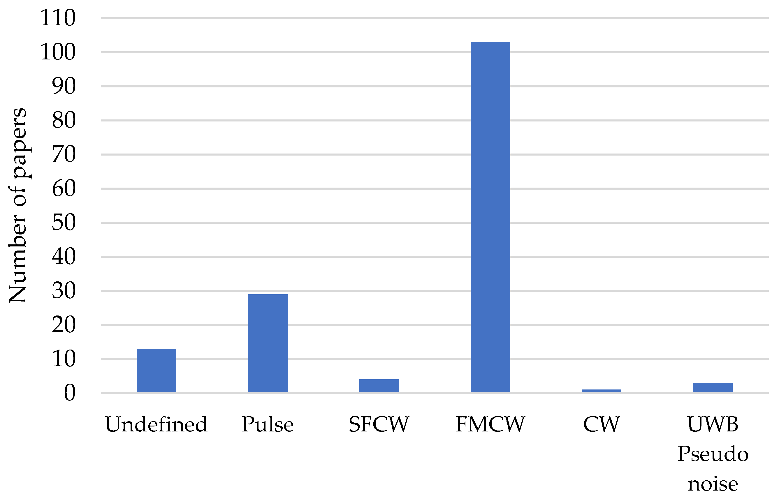
4.1. Radar Signal Modulations
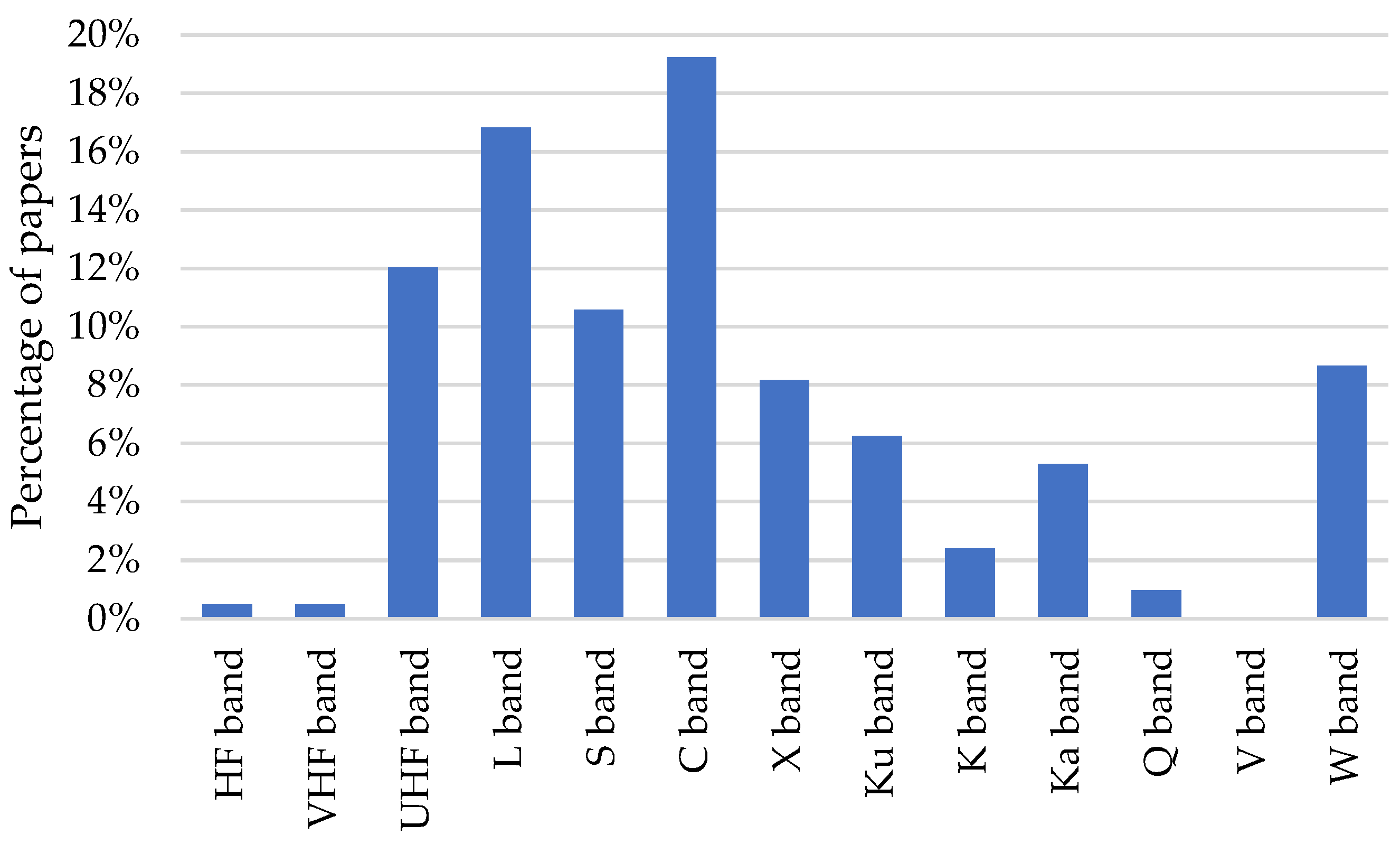
4.2. Operative Band
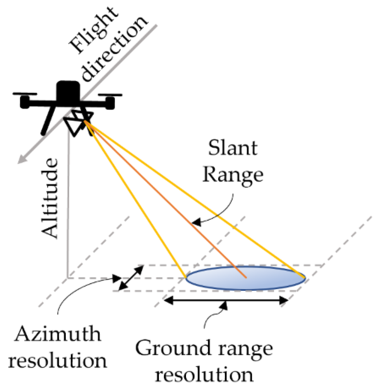
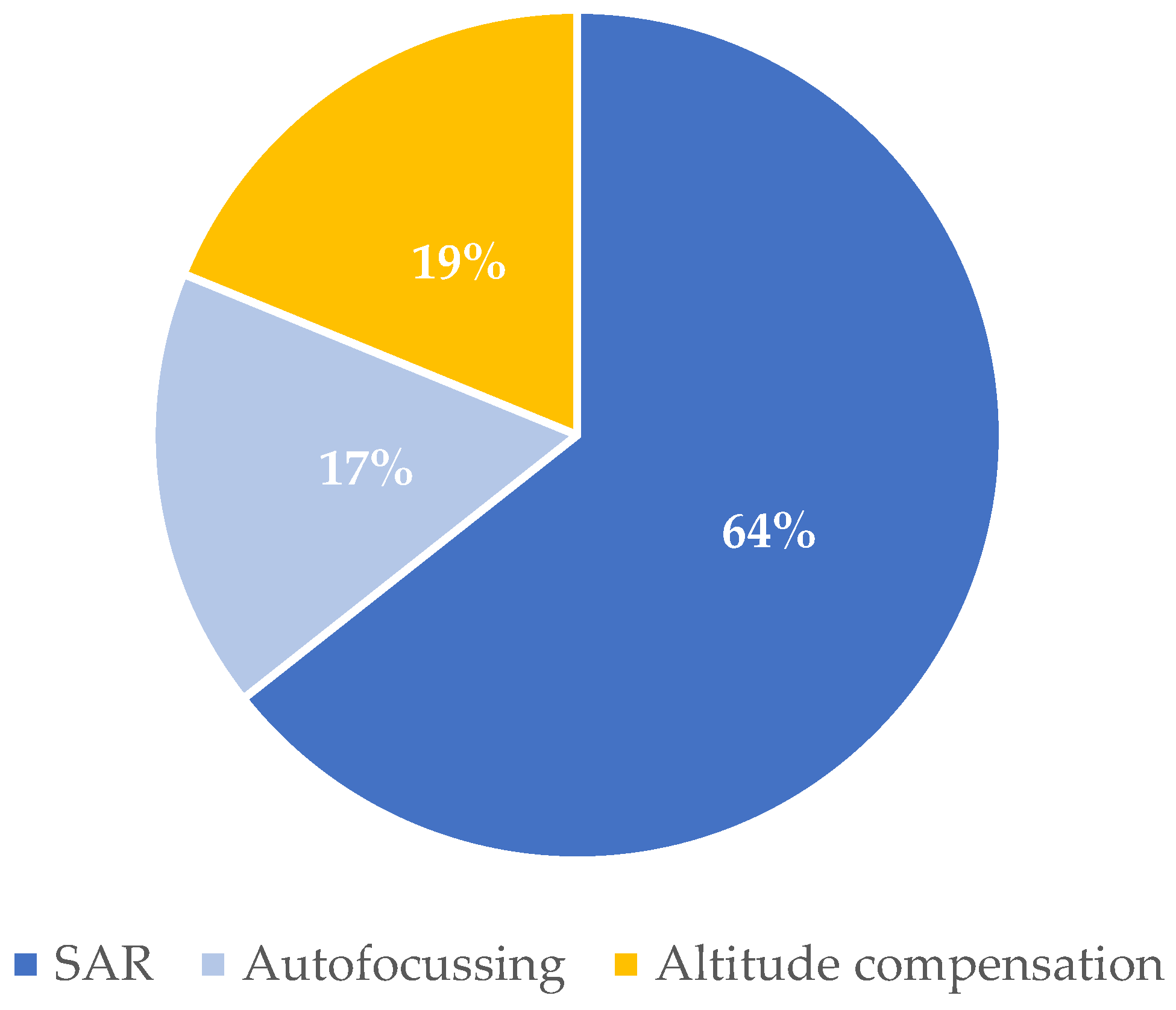
4.3. Imaging Method
5. Remote Sensing Applications
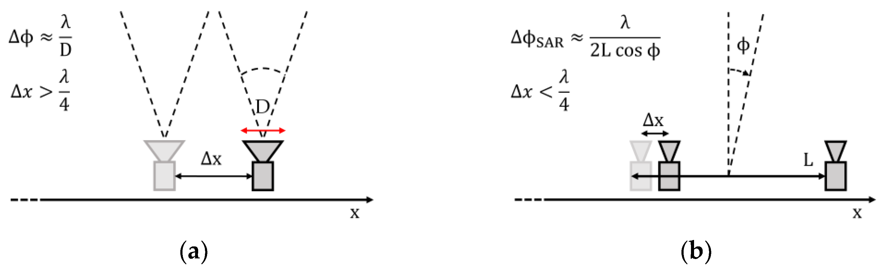
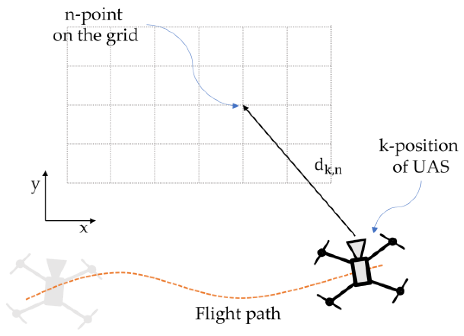
5.1. Synthetic Aperture Radar
5.2. Ground Penetrating Radar
6. Discussion
7. Conclusions
Author Contributions
Funding
Data Availability Statement
Conflicts of Interest
References
- Zhang, C.; Kovacs, J.M. The Application of Small Unmanned Aerial Systems for Precision Agriculture: A Review. Precis. Agric. 2012, 13, 693–712. [Google Scholar] [CrossRef]
- Manfreda, S.; McCabe, M.F.; Miller, P.E.; Lucas, R.; Pajuelo Madrigal, V.; Mallinis, G.; Ben Dor, E.; Helman, D.; Estes, L.; Ciraolo, G.; et al. On the Use of Unmanned Aerial Systems for Environmental Monitoring. Remote Sens. 2018, 10, 641. [Google Scholar] [CrossRef] [Green Version]
- Wang, D.; Shao, Q.; Yue, H. Surveying Wild Animals from Satellites, Manned Aircraft and Unmanned Aerial Systems (UASs): A Review. Remote Sens. 2019, 11, 1308. [Google Scholar] [CrossRef] [Green Version]
- Hardin, P.J.; Lulla, V.; Jensen, R.R.; Jensen, J.R. Small Unmanned Aerial Systems (SUAS) for Environmental Remote Sensing: Challenges and Opportunities Revisited. GIScience Remote Sens. 2019, 56, 309–322. [Google Scholar] [CrossRef]
- Adamopoulos, E.; Rinaudo, F. UAS-Based Archaeological Remote Sensing: Review, Meta-Analysis and State-of-the-Art. Drones 2020, 4, 46. [Google Scholar] [CrossRef]
- Poley, L.G.; McDermid, G.J. A Systematic Review of the Factors Influencing the Estimation of Vegetation Aboveground Biomass Using Unmanned Aerial Systems. Remote Sens. 2020, 12, 1052. [Google Scholar] [CrossRef] [Green Version]
- Vélez-Nicolás, M.; García-López, S.; Barbero, L.; Ruiz-Ortiz, V.; Sánchez-Bellón, Á. Applications of Unmanned Aerial Systems (UASs) in Hydrology: A Review. Remote Sens. 2021, 13, 1359. [Google Scholar] [CrossRef]
- Colomina, I.; Molina, P. Unmanned Aerial Systems for Photogrammetry and Remote Sensing: A Review. ISPRS J. Photogramm. Remote Sens. 2014, 92, 79–97. [Google Scholar] [CrossRef] [Green Version]
- Pieraccini, M.; Miccinesi, L. Ground-Based Radar Interferometry: A Bibliographic Review. Remote Sens. 2019, 11, 1029. [Google Scholar] [CrossRef] [Green Version]
- Cruz, H.; Véstias, M.; Monteiro, J.; Neto, H.; Duarte, R.P. A Review of Synthetic-Aperture Radar Image Formation Algorithms and Implementations: A Computational Perspective. Remote Sens. 2022, 14, 1258. [Google Scholar] [CrossRef]
- Zaugg, E.C.; Hudson, D.L.; Long, D.G. The BYU ΜSAR: A Small, Student-Built SAR for UAV Operation. In Proceedings of the 2006 IEEE International Symposium on Geoscience and Remote Sensing, Denver, CO, USA, 31 July–2 August 2006; pp. 411–414. [Google Scholar]
- García-Fernández, M.; López, Y.Á.; Andrés, F.L.-H. Airborne Multi-Channel Ground Penetrating Radar for Improvised Explosive Devices and Landmine Detection. IEEE Access 2020, 8, 165927–165943. [Google Scholar] [CrossRef]
- Jenssen, R.O.R.; Eckerstorfer, M.; Jacobsen, S. Drone-Mounted Ultrawideband Radar for Retrieval of Snowpack Properties. IEEE Trans. Instrum. Meas. 2020, 69, 221–230. [Google Scholar] [CrossRef] [Green Version]
- Frey, O.; Werner, C.L.; Coscione, R. Car-Borne and UAV-Borne Mobile Mapping of Surface Displacements with a Compact Repeat-Pass Interferometric SAR System at L-Band. In Proceedings of the IGARSS 2019–2019 IEEE International Geoscience and Remote Sensing Symposium, Yokohama, Japan, 28 July–2 August 2019; pp. 274–277. [Google Scholar]
- Chen, Y.; Hakala, T.; Karjalainen, M.; Feng, Z.; Tang, J.; Litkey, P.; Kukko, A.; Jaakkola, A.; Hyyppä, J. UAV-Borne Profiling Radar for Forest Research. Remote Sens. 2017, 9, 58. [Google Scholar] [CrossRef] [Green Version]
- Zotero | Your Personal Research Assistant. Available online: https://www.zotero.org/start (accessed on 8 April 2019).
- Drone Laws [By Countries, States, Cities]–[Updated 13 July 2022]. Available online: https://drone-laws.com/ (accessed on 20 September 2022).
- Vesecky, J.F.; Cornwall, J.M. Integrated Design of Synthetic Aperture Radars for Unmanned Aircraft. In Proceedings of the IGARSS ’96. 1996 International Geoscience and Remote Sensing Symposium, Lincoln, NE, USA, 31 May 1996; Volume 4, pp. 2347–2348. [Google Scholar]
- Civil Drones (Unmanned Aircraft). Available online: https://www.easa.europa.eu/domains/civil-drones (accessed on 25 July 2022).
- Drone Laws in China [Updated 13 July 2022]. Available online: https://drone-laws.com/drone-laws-in-china/ (accessed on 25 July 2022).
- Drone Laws in India [Updated 14 July 2022]. Available online: https://drone-laws.com/drone-laws-in-india/ (accessed on 25 July 2022).
- Remotely Piloted Aircraft System (RPAS). Directorate General of Civil Aviation, India. Available online: https://www.dgca.gov.in/digigov-portal/?page=jsp/dgca/InventoryList/headerblock/drones/RPAS.html (accessed on 25 July 2022).
- Canada, T. Flying Your Drone Safely and Legally. Available online: https://tc.canada.ca/en/aviation/drone-safety/learn-rules-you-fly-your-drone/flying-your-drone-safely-legally (accessed on 2 August 2022).
- Unmanned Aircraft Systems (UAS)|Federal Aviation Administration. Available online: https://www.faa.gov/uas (accessed on 25 July 2022).
- Pieraccini, M. Noise Performance Comparison Between Continuous Wave and Stroboscopic Pulse Ground Penetrating Radar. IEEE Geosci. Remote Sens. Lett. 2018, 15, 222–226. [Google Scholar] [CrossRef]
- Jenssen, R.O.R.; Jacobsen, S. Drone-Mounted UWB Snow Radar: Technical Improvements and Field Results. J. Electromagn. Waves Appl. 2020, 34, 1930–1954. [Google Scholar] [CrossRef]
- Jenssen, R.O.R.; Jacobsen, S.K. Measurement of Snow Water Equivalent Using Drone-Mounted Ultra-Wide-Band Radar. Remote Sens. 2021, 13, 2610. [Google Scholar] [CrossRef]
- Patel, M.; Ferguson, P. Tracking and Estimation of a Swaying Payload Using a LiDAR and an Extended Kalman Filter. In Proceedings of the 2021 IEEE International Symposium on Robotic and Sensors Environments (ROSE), Piscataway, NJ, USA, 28–29 October 2021; pp. 1–7. [Google Scholar]
- Garcia-Fernandez, M.; Alvarez-Lopez, Y.; Heras, F.L.; Gonzalez-Valdes, B.; Rodriguez-Vaqueiro, Y.; Pino, A.; Arboleya-Arboleya, A. GPR System Onboard a UAV for Non-Invasive Detection of Buried Objects. In Proceedings of the 2018 IEEE International Symposium on Antennas and Propagation & USNC/URSI National Radio Science Meeting, Boston, MA, USA, 8–13 July 2018; pp. 1967–1968. [Google Scholar]
- Schartel, M.; Prakasan, K.; Hügler, P.; Burr, R.; Mayer, W.; Waldschmidt, C. A Multicopter-Based Focusing Method for Ground Penetrating Synthetic Aperture Radars. In Proceedings of the IGARSS 2018–2018 IEEE International Geoscience and Remote Sensing Symposium, Valencia, Spain, 22–27 July 2018; pp. 5420–5423. [Google Scholar]
- Ding, M.-L.; Ding, C.-B.; Tang, L.; Wang, X.-M.; Qu, J.-M.; Wu, R. A W-Band 3-D Integrated Mini-SAR System With High Imaging Resolution on UAV Platform. IEEE Access 2020, 8, 113601–113609. [Google Scholar] [CrossRef]
- Ding, M.; Liang, X.; Tang, L.; Wen, Z.; Wang, X.; Wang, Y. Micro FMCW SAR with High Resolution for Mini UAV. In Proceedings of the 2018 International Conference on Microwave and Millimeter Wave Technology (ICMMT), Chengdu, China, 7–11 May 2018; pp. 1–3. [Google Scholar]
- Wang, Y.; Lou, L.; Chen, B.; Zhang, Y.; Tang, K.; Qiu, L.; Liu, S.; Zheng, Y. A 260-MW Ku-Band FMCW Transceiver for Synthetic Aperture Radar Sensor With 1.48-GHz Bandwidth in 65-Nm CMOS Technology. IEEE Trans. Microw. Theory Tech. 2017, 65, 4385–4399. [Google Scholar] [CrossRef]
- Ludeno, G.; Catapano, I.; Renga, A.; Vetrella, A.R.; Fasano, G.; Soldovieri, F. Assessment of a Micro-UAV System for Microwave Tomography Radar Imaging. Remote Sens. Environ. 2018, 212, 90–102. [Google Scholar] [CrossRef]
- Fasano, G.; Renga, A.; Vetrella, A.R.; Ludeno, G.; Catapano, I.; Soldovieri, F. Proof of Concept of Micro-UAV-Based Radar Imaging. In Proceedings of the 2017 International Conference on Unmanned Aircraft Systems (ICUAS), Miami, FL, USA, 13–16 June 2017; pp. 1316–1323. [Google Scholar]
- Esposito, G.; Noviello, C.; Soldovieri, F.; Catapano, I.; Fasano, G.; Gagliarde, G.; Luisi, G.; Saccoccio, F. The UAV Radar Imaging Prototype Developed in the Frame of the VESTA Project. In Proceedings of the 2020 IEEE Radar Conference (RadarConf20), Florence, Italy, 21–25 September 2020; pp. 1–5. [Google Scholar]
- Ye, E.; Shaker, G.; Melek, W. Lightweight Low-Cost UAV Radar Terrain Mapping. In Proceedings of the 2019 13th European Conference on Antennas and Propagation (EuCAP), Krakow, Poland, 31 March–5 April 2019; pp. 1–5. [Google Scholar]
- Pieraccini, M.; Miccinesi, L. ArcSAR: Theory, Simulations, and Experimental Verification. IEEE Trans. Microw. Theory Tech. 2017, 65, 293–301. [Google Scholar] [CrossRef]
- Schartel, M.; Bähnemann, R.; Burr, R.; Mayer, W.; Waldschmidt, C. Position Acquisition for a Multicopter-Based Synthetic Aperture Radar. In Proceedings of the 2019 20th International Radar Symposium (IRS), Ulm, Germany, 26–28 June 2019; pp. 1–7. [Google Scholar]
- Pieraccini, M.; Miccinesi, L. ArcSAR for Detecting Target Elevation. Electron. Lett. 2016, 52, 1559–1561. [Google Scholar] [CrossRef]
- Viviani, F.; Michelini, A.; Mayer, L.; Conni, F. IBIS-ArcSAR: An Innovative Ground-Based SAR System for Slope Monitoring. In Proceedings of the IGARSS 2018–2018 IEEE International Geoscience and Remote Sensing Symposium, Valencia, Spain, 22–27 July 2018; pp. 1348–1351. [Google Scholar]
- Pieraccini, M.; Miccinesi, L. RotoSAR for Monitoring Bridges. In Proceedings of the European Microwave Week 2017: “A Prime Year for a Prime Event”, EuMW 2017—Conference Proceedings; 14th European Microwave Conference, EURAD 2017, Nuremberg, Germany, 11–13 October 2018; Volume 2018, pp. 311–314. [Google Scholar]
- Bekar, A.; Antoniou, M.; Baker, C.J. Low-Cost, High-Resolution, Drone-Borne SAR Imaging. IEEE Trans. Geosci. Remote Sens. 2022, 60, 1–11. [Google Scholar] [CrossRef]
- Engel, M.; Heinzel, A.; Schreiber, E.; Dill, S.; Peichl, M. Recent Results of a UAV-Based Synthetic Aperture Radar for Remote Sensing Applications. In Proceedings of the EUSAR 2021; 13th European Conference on Synthetic Aperture Radar, Online, 29 March–1 April 2021; pp. 1–5. [Google Scholar]
- Burr, R.; Schartel, M.; Mayer, W.; Walter, T.; Waldschmidt, C. Uav-Based Polarimetric Synthetic Aperture Radar for Mine Detection. In Proceedings of the IGARSS 2019–2019 IEEE International Geoscience and Remote Sensing Symposium, Yokohama, Japan, 28 July–2 August 2019; pp. 9208–9211. [Google Scholar]
- Almutiry, M. UAV Tomographic Synthetic Aperture Radar for Landmine Detection. Eng. Technol. Appl. Sci. Res. 2020, 10, 5933–5939. [Google Scholar] [CrossRef]
- Burr, R.; Schartel, M.; Grathwohl, A.; Mayer, W.; Walter, T.; Waldschmidt, C. UAV-Borne FMCW InSAR for Focusing Buried Objects. IEEE Geosci. Remote Sens. Lett. 2022, 19, 1–5. [Google Scholar] [CrossRef]
- Burr, R.; Schartel, M.; Mayer, W.; Walter, T.; Waldschmidt, C. Lightweight Broadband Antennas for UAV Based GPR Sensors. In Proceedings of the 2018 15th European Radar Conference (EuRAD), Madrid, Spain, 26–28 September 2018; pp. 245–248. [Google Scholar]
- Schartel, M.; Burr, R.; Mayer, W.; Docci, N.; Waldschmidt, C. UAV-Based Ground Penetrating Synthetic Aperture Radar. In Proceedings of the 2018 IEEE MTT-S International Conference on Microwaves for Intelligent Mobility (ICMIM), Munich, Germany, 16–18 April 2018; pp. 1–4. [Google Scholar]
- Garcia-Fernandez, M.; Alvarez-Lopez, Y.; Heras, F.L. 3D-SAR Processing of UAV-Mounted GPR Measurements: Dealing with Non-Uniform Sampling. In Proceedings of the 2020 14th European Conference on Antennas and Propagation (EuCAP), Copenhagen, Denmark, 15–20 March 2020; pp. 1–5. [Google Scholar]
- Garcia-Fernandez, M.; Alvarez-Lopez, Y.; Las Heras, F. Autonomous Airborne 3D SAR Imaging System for Subsurface Sensing: UWB-GPR on Board a UAV for Landmine and IED Detection. Remote Sens. 2019, 11, 2357. [Google Scholar] [CrossRef] [Green Version]
- García-Fernández, M.; Álvarez-Narciandi, G.; López, Y.Á.; Andrés, F.L.-H. SAFEDRONE Project: Development of a UAV-Based High-Resolution GPR System for IED Detection. In Proceedings of the 2022 16th European Conference on Antennas and Propagation (EuCAP), Madrid, Spain, 27 March–1 April 2022; pp. 1–5. [Google Scholar]
- Grathwohl, A.; Hinz, P.; Burr, R.; Steiner, M.; Waldschmidt, C. Experimental Study on the Detection of Avalanche Victims Using an Airborne Ground Penetrating Synthetic Aperture Radar. In Proceedings of the 2021 IEEE Radar Conference (RadarConf21), Atlanta, GA, USA, 7–14 May 2021; pp. 1–6. [Google Scholar]
- Lort, M.; Aguasca, A.; López-Martínez, C.; Marín, T.M. Initial Evaluation of SAR Capabilities in UAV Multicopter Platforms. IEEE J. Sel. Top. Appl. Earth Obs. Remote Sens. 2018, 11, 127–140. [Google Scholar] [CrossRef] [Green Version]
- Wahl, D.E.; Eichel, P.H.; Ghiglia, D.C.; Jakowatz, C.V. Phase Gradient Autofocus-a Robust Tool for High Resolution SAR Phase Correction. IEEE Trans. Aerosp. Electron. Syst. 1994, 30, 827–835. [Google Scholar] [CrossRef] [Green Version]
- Saeedi, J.; Faez, K. A Back-Projection Autofocus Algorithm Based on Flight Trajectory Optimization for Synthetic Aperture Radar Imaging. Multidimens. Syst. Signal Process. 2016, 27, 411–431. [Google Scholar] [CrossRef]
- Ding, Z.; Zhu, K.; Zhang, T.; Li, L.; Wang, Y.; Wang, G.; Gao, Y.; Wei, Y.; Zeng, T. An Autofocus Back Projection Algorithm for GEO SAR Based on Minimum Entropy. IEEE Trans. Geosci. Remote Sens. 2022, 60, 1–14. [Google Scholar] [CrossRef]
- Ding, Z.; Li, L.; Wang, Y.; Zhang, T.; Gao, W.; Zhu, K.; Zeng, T.; Yao, D. An Autofocus Approach for UAV-Based Ultrawideband Ultrawidebeam SAR Data With Frequency-Dependent and 2-D Space-Variant Motion Errors. IEEE Trans. Geosci. Remote Sens. 2022, 60, 1–18. [Google Scholar] [CrossRef]
- Liu, W.; Feng, H.; Lu, Y. Ka-Band Drone SAR Flying without GPS. In Proceedings of the 2021 7th Asia-Pacific Conference on Synthetic Aperture Radar (APSAR), Bali, Indonesia, 1–3 November 2021; pp. 1–4. [Google Scholar]
- Zaugg, E.; Edwards, M.; Long, D.; Stringham, C. Developments in Compact High-Performance Synthetic Aperture Radar Systems for Use on Small Unmanned Aircraft. In Proceedings of the 2011 Aerospace Conference, Big Sky, MT, USA, 5–12 March 2011; pp. 1–14. [Google Scholar]
- Tetuko, S.S.J.; Koo, V.C.; Lim, T.S.; Kawai, T.; Ebinuma, T.; Izumi, Y.; Baharuddin, M.Z.; Gao, S.; Ito, K. Development of Circularly Polarized Synthetic Aperture Radar On-Board UAV JX-1. Int. J. Remote Sens. 2017, 38, 2745–2756. [Google Scholar] [CrossRef]
- Wu, K.; Rodriguez, G.A.; Zajc, M.; Jacquemin, E.; Clément, M.; De Coster, A.; Lambot, S. A New Drone-Borne GPR for Soil Moisture Mapping. Remote Sens. Environ. 2019, 235, 111456. [Google Scholar] [CrossRef]
- Essen, H.; Johannes, W.; Stanko, S.; Sommer, R.; Wahlen, A.; Wilcke, J. High Resolution W-Band UAV SAR. In Proceedings of the 2012 IEEE International Geoscience and Remote Sensing Symposium, Munich, Germany, 22–27 July 2012; pp. 5033–5036. [Google Scholar]
- Kim, J.; Kim, S.; Lee, W.; Shin, S.; Choi, Y.; Ka, M.-H. Design and Implemetation of Compact 77 GHz Synthetic Aperture Radar for Drone Based Applications. In Proceedings of the 2019 6th Asia-Pacific Conference on Synthetic Aperture Radar (APSAR), Xiamen, China, 26–29 November 2019; pp. 1–5. [Google Scholar]
- Moreira, L.; Castro, F.; Góes, J.A.; Bins, L.; Teruel, B.; Fracarolli, J.; Castro, V.; Alcântara, M.; Oré, G.; Luebeck, D.; et al. A Drone-Borne Multiband DInSAR: Results and Applications. In Proceedings of the 2019 IEEE Radar Conference (RadarConf), Boston, MA, USA, 22–26 April 2019; pp. 1–6. [Google Scholar]
- Deguchi, T.; Sugiyama, T.; Kishimoto, M. R&D of drone-borne SAR system. Int. Arch. Photogramm. Remote Sens. Spat. Inf. Sci. 2019, XLII-2/W13, 263–267. [Google Scholar] [CrossRef] [Green Version]
- Deguchi, T.; Sugiyama, T.; Kishimoto, M. Development of SAR System Installable on a Drone. In Proceedings of the EUSAR 2021; 13th European Conference on Synthetic Aperture Radar, Online, 29 March–1 April 2021; pp. 1–3. [Google Scholar]
- Luebeck, D.; Wimmer, C.; Moreira, L.F.; Alcântara, M.; Oré, G.; Góes, J.A.; Oliveira, L.P.; Teruel, B.; Bins, L.S.; Gabrielli, L.H.; et al. Drone-Borne Differential SAR Interferometry. Remote Sens. 2020, 12, 778. [Google Scholar] [CrossRef] [Green Version]
- Lv, Z.; Li, F.; Qiu, X.; Ding, C. Effects of Motion Compensation Residual Error and Polarization Distortion on UAV-Borne PolInSAR. Remote Sens. 2021, 13, 618. [Google Scholar] [CrossRef]
- Oré, G.; Alcântara, M.S.; Góes, J.A.; Teruel, B.; Oliveira, L.P.; Yepes, J.; Castro, V.; Bins, L.S.; Castro, F.; Luebeck, D.; et al. Predicting Sugarcane Harvest Date and Productivity with a Drone-Borne Tri-Band SAR. Remote Sens. 2022, 14, 1734. [Google Scholar] [CrossRef]
- Oré, G.; Alcântara, M.S.; Góes, J.A.; Oliveira, L.P.; Yepes, J.; Teruel, B.; Castro, V.; Bins, L.S.; Castro, F.; Luebeck, D.; et al. Crop Growth Monitoring with Drone-Borne DInSAR. Remote Sens. 2020, 12, 615. [Google Scholar] [CrossRef] [Green Version]
- Moreira, L.; Lübeck, D.; Wimmer, C.; Castro, F.; Góes, J.A.; Castro, V.; Alcântara, M.; Oré, G.; Oliveira, L.P.; Bins, L.; et al. Drone-Borne P-Band Single-Pass InSAR. In Proceedings of the 2020 IEEE Radar Conference (RadarConf20), Florence, Italy, 21–25 September 2020; pp. 1–6. [Google Scholar]
- Hawkins, B.; Anderson, M.; Prager, S.; Chung, S.-I.; Lavalle, M. Experiments with Small UAS to Support SAR Tomographic Mission Formulation. In Proceedings of the 2021 IEEE International Geoscience and Remote Sensing Symposium IGARSS, Brussels, Belgium, 11–16 July 2021; pp. 643–646. [Google Scholar]
- Gromek, D.; Samczynski, P.; Kulpa, K.; Cruz, G.C.S.; Oliveira, T.M.M.; Félix, L.F.S.; Gonçalves, P.A.V.; Silva, C.M.B.P.; Santos, A.L.C.; Morgado, J.A.P. C-Band SAR Radar Trials Using UAV Platform: Experimental Results of SAR System Integration on a UAV Carrier. In Proceedings of the 2016 17th International Radar Symposium (IRS), Krakow, Poland, 10–12 May 2016; pp. 1–5. [Google Scholar]
- Hu, X.; Ma, C.; Hu, R.; Yeo, T.S. Imaging for Small UAV-Borne FMCW SAR. Sensors 2019, 19, 87. [Google Scholar] [CrossRef] [Green Version]
- Yan, J.; Peng, Z.; Hong, H.; Chu, H.; Zhu, X.; Li, C. Vital-SAR-Imaging With a Drone-Based Hybrid Radar System. IEEE Trans. Microw. Theory Tech. 2018, 66, 5852–5862. [Google Scholar] [CrossRef]
- Wu, Y.; Li, J.; Yuan, Y.; Qin, A.K.; Miao, Q.-G.; Gong, M.-G. Commonality Autoencoder: Learning Common Features for Change Detection From Heterogeneous Images. IEEE Trans. Neural Netw. Learn. Syst. 2022, 33, 4257–4270. [Google Scholar] [CrossRef]
- Wu, Y.; Xiao, Z.; Liu, S.; Miao, Q.; Ma, W.; Gong, M.; Xie, F.; Zhang, Y. A Two-Step Method for Remote Sensing Images Registration Based on Local and Global Constraints. IEEE J. Sel. Top. Appl. Earth Obs. Remote Sens. 2021, 14, 5194–5206. [Google Scholar] [CrossRef]
- Caporossi, P.; Mazzanti, P.; Bozzano, F. Digital Image Correlation (DIC) Analysis of the 3 December 2013 Montescaglioso Landslide (Basilicata, Southern Italy): Results from a Multi-Dataset Investigation. ISPRS Int. J. Geo-Inf. 2018, 7, 372. [Google Scholar] [CrossRef] [Green Version]
- Sipos, D.; Planinsic, P.; Gleich, D. On Drone Ground Penetrating Radar for Landmine Detection. In Proceedings of the 2017 First International Conference on Landmine: Detection, Clearance and Legislations (LDCL), Beirut, Lebanon, 26–28 April 2017; pp. 1–4. [Google Scholar]
- Dill, S.; Schreiber, E.; Engel, M.; Heinzel, A.; Peichl, M. A Drone Carried Multichannel Synthetic Aperture Radar for Advanced Buried Object Detection. In Proceedings of the 2019 IEEE Radar Conference (RadarConf), Boston, MA, USA, 22–26 April 2019; pp. 1–6. [Google Scholar]
- Garcia-Fernandez, M.; Morgenthaler, A.; Alvarez-Lopez, Y.; Las Heras, F.; Rappaport, C. Bistatic Landmine and IED Detection Combining Vehicle and Drone Mounted GPR Sensors. Remote Sens. 2019, 11, 2299. [Google Scholar] [CrossRef] [Green Version]
- Garcia-Fernandez, M.; Alvarez-Lopez, Y.; Las Heras, F.; Morgenthaler, A.; Rappaport, C. Analysis of Multistatic Vehicle-Drone Ground Penetrating Radar Configurations for Mine Detection. In Proceedings of the 2019 IEEE International Symposium on Antennas and Propagation and USNC-URSI Radio Science Meeting, Atlanta, GA, USA, 7–12 July 2019; pp. 1637–1638. [Google Scholar]
- Rong, Y.; Gutierrez, R.; Mishra, K.V.; Bliss, D.W. Noncontact Vital Sign Detection With UAV-Borne Radars: An Overview of Recent Advances. IEEE Veh. Technol. Mag. 2021, 16, 118–128. [Google Scholar] [CrossRef]
- Chandra, M.; Tanzi, T.J. Drone-Borne GPR Design: Propagation Issues. Comptes Rendus Phys. 2018, 19, 72–84. [Google Scholar] [CrossRef]
- Simpson, C.D.; Kolpuke, S.; Awasthi, A.K.; Luong, T.; Memari, S.; Yan, S.; Taylor, R.; Larson, J.; Clement, P. Development of A UAS-Based Ultra-Wideband Radar for Fine-Resolution Soil Moisture Measurements. In Proceedings of the 2021 IEEE Radar Conference (RadarConf21), San Antonio, TX, USA, 1–5 May 2021; pp. 1–4. [Google Scholar]
- Pantoja, J.J.; Vega, F.; Prado, L.; Yang, Q.; AlAli, B.; Kasmi, C.; Moreira, L.; Lübeck, D.; Wimmer, C. Drone-Borne Synthetic Aperture Radar for GPR Applications: Buried Pipe Inspection. In Proceedings of the 2022 3rd URSI Atlantic and Asia Pacific Radio Science Meeting (AT-AP-RASC), Gran Canaria, Spain, 29 May–3 June 2022; pp. 1–2. [Google Scholar]
- Tan, A.; Eccleston, K.; Platt, I.; Woodhead, I.; Rack, W.; McCulloch, J. The Design of a UAV Mounted Snow Depth Radar: Results of Measurements on Antarctic Sea Ice. In Proceedings of the 2017 IEEE Conference on Antenna Measurements & Applications (CAMA), Tsukuba, Japan, 4–6 December 2017; pp. 316–319. [Google Scholar]
- Vergnano, A.; Franco, D.; Godio, A. Drone-Borne Ground-Penetrating Radar for Snow Cover Mapping. Remote Sens. 2022, 14, 1763. [Google Scholar] [CrossRef]
- García Fernández, M.; Álvarez López, Y.; Arboleya Arboleya, A.; González Valdés, B.; Rodríguez Vaqueiro, Y.; Las-Heras Andrés, F.; Pino García, A. Synthetic Aperture Radar Imaging System for Landmine Detection Using a Ground Penetrating Radar on Board a Unmanned Aerial Vehicle. IEEE Access 2018, 6, 45100–45112. [Google Scholar] [CrossRef]
- UAV Collision Avoidance Radar_Nanoradar-Accurate Measure Intellgent Sense. Available online: http://en.nanoradar.cn/Article/detail/id/287.html (accessed on 23 September 2022).
- Miccinesi, L.; Bigazzi, L.; Consumi, T.; Pieraccini, M.; Beni, A.; Boni, E.; Basso, M. Geo-Referenced Mapping through an Anti-Collision Radar Aboard an Unmanned Aerial System. Drones 2022, 6, 72. [Google Scholar] [CrossRef]
- Matrice 300 RTK. Available online: https://www.dji.com/matrice-300?site=brandsite&from=nav (accessed on 23 September 2022).
- Bigazzi, L.; Basso, M.; Boni, E.; Innocenti, G.; Pieraccini, M. A Multilevel Architecture for Autonomous UAVs. Drones 2021, 5, 55. [Google Scholar] [CrossRef]


| Spaceborne | Terrestrial | UAS-Borne | |
|---|---|---|---|
| Autonomy | ∞ | ∞ | 20/50 min |
| Weather condition operativity | Operative in each weather condition | Operative in each weather condition | Could not be operated in each weather condition |
| Return time | Days | Minutes | Minutes–hours |
| Resolution | Constant with the range (spatial resolution) | Function of range (angular resolution) | Constant with range or angles depending on operative modality |
| Coverage | Global | 1 km2 | 10 km2 |
| Cat. | SUBCATEGORY LIMITATION | UAS REQUIREMENTS |
|---|---|---|
| A1 | Overflight of UAS is permitted over people outside of an operation. Flying close to a populated area is allowed. | Private construction < 250 g and < 19 m/s |
| Type C0 (<250 g) | ||
| Type C1 (<900 g, e-ID, and Geo-awareness) | ||
| A2 | Flying is allowed near people outside of an operation by maintaining a safety distance of 5–30 m. Flying close to a populated area is allowed. | Type C2 (<4 kg with low speed, e-ID, and Geo-awareness) |
| A3 | Operation in areas where people are outside of an operation are not endangered by maintaining a minimum safety distance of 150 m from any populated area. | Private construction < 25 kg |
| Type C2 (<4 kg, e-ID, and Geo-awareness) | ||
| Type C3 (<25 kg, e-ID, and Geo-awareness) | ||
| Type C4 (>25 kg) |
Publisher’s Note: MDPI stays neutral with regard to jurisdictional claims in published maps and institutional affiliations. |
© 2022 by the authors. Licensee MDPI, Basel, Switzerland. This article is an open access article distributed under the terms and conditions of the Creative Commons Attribution (CC BY) license (https://creativecommons.org/licenses/by/4.0/).
Share and Cite
Miccinesi, L.; Beni, A.; Pieraccini, M. UAS-Borne Radar for Remote Sensing: A Review. Electronics 2022, 11, 3324. https://doi.org/10.3390/electronics11203324
Miccinesi L, Beni A, Pieraccini M. UAS-Borne Radar for Remote Sensing: A Review. Electronics. 2022; 11(20):3324. https://doi.org/10.3390/electronics11203324
Chicago/Turabian StyleMiccinesi, Lapo, Alessandra Beni, and Massimiliano Pieraccini. 2022. "UAS-Borne Radar for Remote Sensing: A Review" Electronics 11, no. 20: 3324. https://doi.org/10.3390/electronics11203324