Article

Versatile Electronics for Microwave Holographic RADAR Based on Software Defined Radio Technology

Department of Information Engineering, Università degli Studi di Firenze, 50139 Florence, Italy
*
Author to whom correspondence should be addressed.
These authors contributed equally to this work.
Electronics 2022, 11(18), 2883; https://doi.org/10.3390/electronics11182883
Submission received: 4 August 2022 / Revised: 1 September 2022 / Accepted: 9 September 2022 / Published: 12 September 2022
(This article belongs to the Special Issue Advances in Radar Technology for Remote Sensing)

Abstract

:
The NATO SPS G-5014 project has shown the possibility of using a holographic RADAR for the detection of anti-personnel mines. To use the RADAR on a robotic scanning system, it must be portable, light, easily integrated with mechanical handling systems and configurable in its operating parameters for optimal performance on different terrains. The novel contribution is to use software programmable electronics to optimize performance and to use a time reference to obtain synchronization between the RADAR samples and the position in space, in order to make it easy to integrate the RADAR on robotic platforms. To achieve these goals we used the Analog Devices “ADALM Pluto” device based on Software Defined Radio technology and a time server. We have obtained a portable system, configurable via software in all its operating parameters and easily integrated on robotic scanning platforms. The paper will show experiments performed on a simulated minefield. The electronics project reported in this work makes holographic RADARs portable and easily reconfigurable, therefore adaptable to different applications from subsurface soil investigations to applications in the field of non-destructive testings.

1. Introduction

The death toll from ERW (Explosive Remnants of War) in 2020 shows an increase from the 5853 victims recorded in 2019 and is more than double the lowest annual total ever recorded (3456 victims in 2013). Eighty percent of the victims were civilians and in 2020 children accounted for half of all civilian victims whose age was known (1872) [1]. These explosive devices, placed during a conflict with enemy forces, can still kill or injure civilians decades later [2].
Electronic technologies developed for mine detection are based on measuring the different physical characteristics (magnetic, mechanical, acoustic, electromagnetic, etc.) of anti-personnel mines compared to other buried objects [3]. The most commonly used physical parameters are: the presence of explosives, the presence of localized metal masses, the shape and size of the suspect object, anomalies in the surface profile of the soil, anomalies in the vegetation [4,5,6].

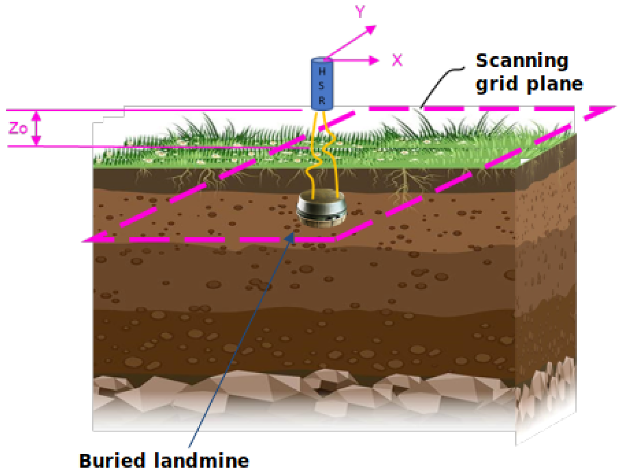
1.1. Microwave Radars for Landmines Detection

To detect low-metal landmines, several armies around the world began using radio wave landmine detectors in the 1980s that operated on the principle of detecting changes in the dielectric permittivity ε r of the soil caused by the presence of a landmine [7]. However, the use of radio-frequency devices for detecting plastic mines presents a high level of false alarms caused both by natural unevenness of the ground and by irregularities of the ground surface. On the market there are solutions based on the combination of several technologies, for example a radio-frequency device combined with a metal detector. Figure 1 illustrates the methods and technolgies for GPR (Ground Penetrating RADAR). Comparing this table with the similar one in [8], we can notice the recent progresses in the field. In particular for this work regarding holographic RADARs can be observed that they operate in the “Space domain”. These types can reduce the level of false alarms thanks to use of the radio frequency to acquire samples in the space domain in order to obtain an image of a target while it is still in the ground [9,10]. These types of RADARs do not requires a modulation of the transmitted signal, which is, generally, a continuous wave signal.

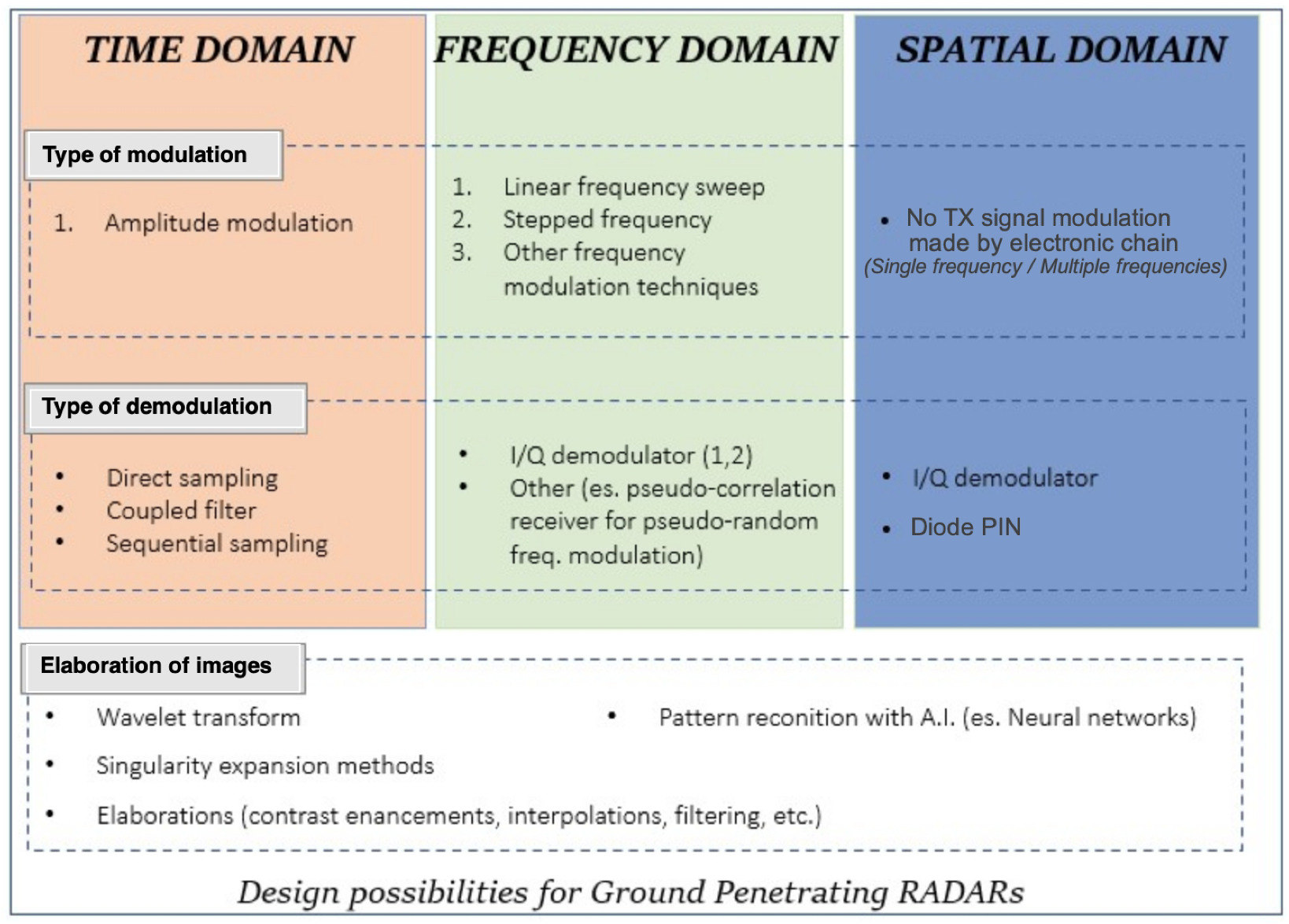
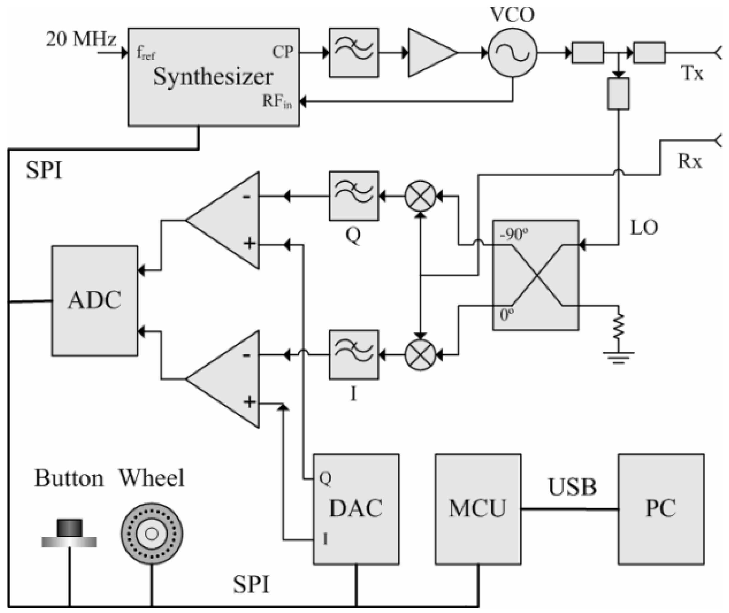
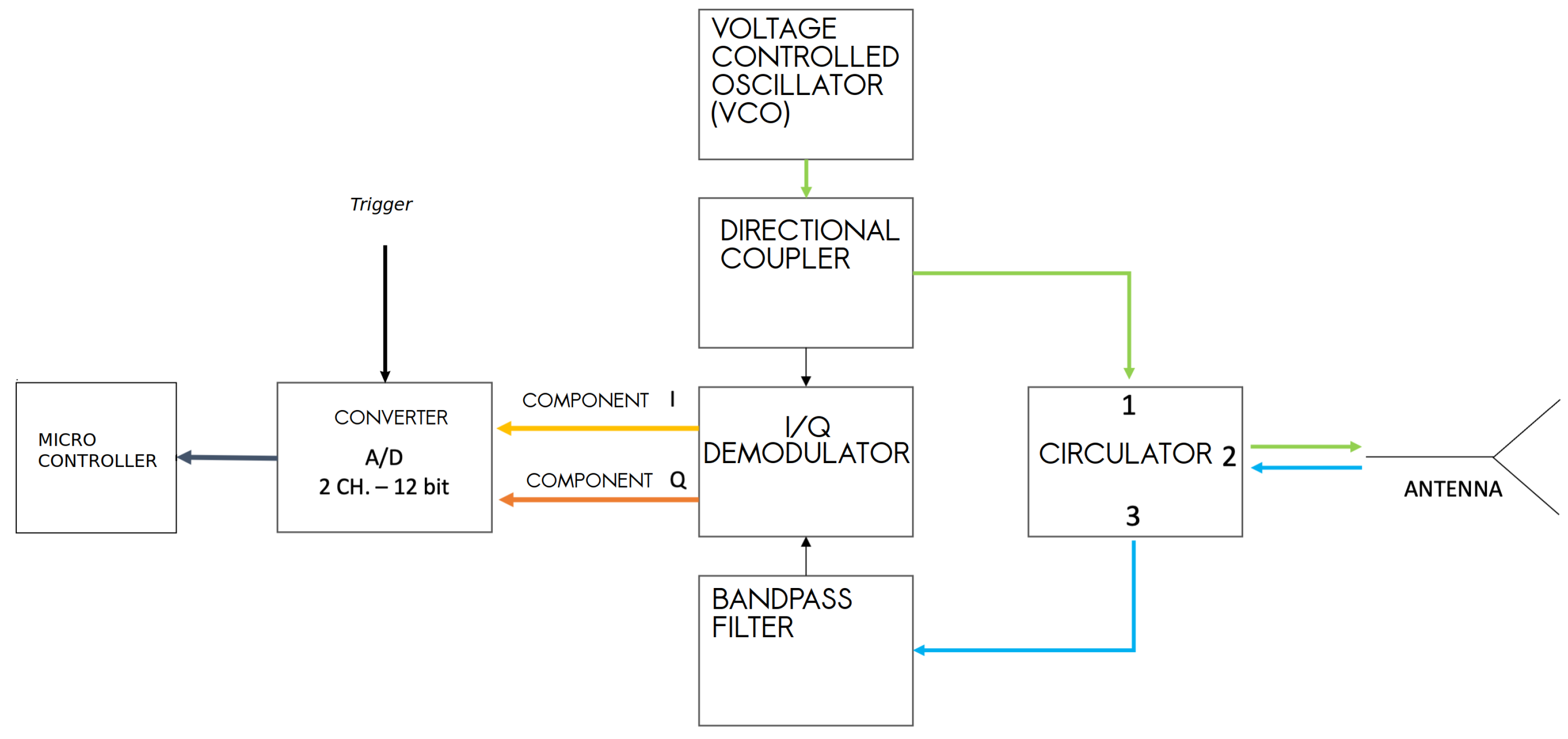
1.2. Recent Advances in Electronics for Holographic Radars

In optics, the term “hologram” indicates the recording of an interference pattern between two electromagnetic waves, one of which is modulated by diffraction due to the presence of an object (the etymology of the term hologram derives from ancient Greek with the meaning of “whole description” or “whole image” to indicate the possibility it offers to reconstruct the three dimensionality of the scene). The first Holographic Radar made by Keigo Iizuka in the 1960s operated at the microwave frequency of 34 GHz and used Polaroid© film to record holograms [11,12]. From the beginning it was evident that for the inspection of dielectric materials, the attenuation of electromagnetic waves in the microwave range represented a challenge for the electronics design. However, the images recorded by the holographic RADARs have a high spatial resolution in the image plane (≈ λ /4). With the RADAR presented in this article the spatial resolution is about 3 cm, with medium dielectric permittivity of terrain ε r = 6 @ 2 GHz. This resolution is necessary to identify characteristic shapes or details of devices up to 10 cm in diameter [13]. This is the feature that motivated the research to be able to use holographic RADARs in the detection of landmines [14]. As indicated in Figure 1 there is no modulation of the transmitted signal. The modulation in amplitude is constituted by the interference pattern obtained, on the receiving antenna, by the wave transmitted (reference wave) and by the wave reflected from the external environment. In general the microwave hologram is obtained by scanning with the Radar antenna the surface of region of interest and reproducing the recorded amplitude of the holographic signal in the spatial domain. Early receiver electronics was based on a peak detector based on a PIN (P-type, intrinsic, N-type) diode. Then the peak voltage was represented as a color scale for each antenna position to generate an image of the interference pattern. An updated version of the receiver is done using a I/Q (In phase/Quadrature) demodulator. In this type of receiver the output of the holographic RADAR are the I and Q components which allow to calculate the amplitude and phase of the received signal (the hologram H x , y = I x , y + i Q x , y ). With the peak detector based RADARs, we obtain a single image that contains the amplitude and phase of the wave front. In this way, the resulting image may not be immediately readable and interpretable and it may be necessary to apply a hologram inversion algorithm to display the three-dimensional image of the scanned target. The electronics based on the I/Q demodulator generate two voltages which are converted into a color scale for each antenna position. The two images obtained represent the amplitude and phase of the hologram. This simplifies and speeds up the reading and interpretation of the information contained in the hologram.
In holographic RADARs it is necessary to correlate samples with space. In the first electronics, spatial correlation of the samples was performed using an ADC board to acquire the samples at specific antenna positions. The ADC was activated by a position encoder. Figure 2 shows the internal architecture of the holographic RADAR “RASCAN 5”. This electronics are built using discrete components and custom hybrid microwave circuits. It is an electronics optimized for the operating frequencies in the range of 6.4 GHz–6.8 GHz and cannot be reconfigured for other types of antenna/frequency.
For the recording of the antenna position during a manual scan with RASCAN radars the adopted solution was a wheel encoder. The sampling step was assigned by the wheel encoder characteristics related to the radar wavelength but cannot be changed for adapting to different radar configurations. For minimizing the spatial sampling errors of manual scan, which depend on both the skills of the operator and from the topography of the investigated surface, the authors proposed the solution of spatial sampling with a remotely controlled robotic platform [15]. The RADAR presented in this work is designed to work with the antenna not in contact with the investigated medium and the acquisition of samples always takes place on a plane with a robotic positioning system. The holographic RADAR used in [16] requires 30 min to cover a 0.75 m2 area by a radial acquisition. To increase the speed of acquisitions, it is necessary to mount the antenna on a two- or three-axial mechanical scanning frame. For the spatial positioning of the RADAR samples, the mechanical frame generates a trigger signal when the antenna arrives in predefined positions in the scanning plane that activates the sampling of the ADC. Figure 3 shows the block diagram of the HSR (Holographic Subsurface RADAR) which was developed during NATO SPS G-5014. This architecture was our starting point for the development of the device presented here. The signal to be radiated originates from a voltage controlled sinusoidal signal generator (VCO: Voltage Controlled Oscillator) in the frequency range (1.97–2.2) GHz. The signal is fed into a directional coupler, whose coupled output forms the reference signal for the I/Q demodulator. The non-attenuated output of the directional coupler is conducted to port 1 of a circulator. The signal exits the consecutive port (port 2) and arrives at the antenna feed. The signal strength is that provided by the VCO, about 7.5 dBm. The signal is radiated and received by the single feed monostatic antenna [17]. The transmitted signal is separated from that received by a three-port circulator. Components I and Q are obtained from a demodulator, using the signal at the output of the directional coupler as a reference. The above components of the complex signal are sampled by the STM32 ARM micro-controller © CortexTM-M7 with a 12-bit analog-digital converter and encoded for storage in a BAG type file, a file format used for storing information and sensor data within the ROS (Robot Operating System) framework.
The formation of the RADAR image occurs thanks to the spatial positioning of the acquired samples in the coordinates of the programmed grid of points ( Figure 4).
Synchronization occurs thanks to the trigger for the ADC generated by the mechanical scanning system. For the construction of the holographic image it is therefore necessary to align the samples according to the scanning path followed by the antenna. This path must be known and predefined. Furthermore, it is not possible, other than mechanically, to apply filters on the signal, modify the sampling frequency of the ADC, adjust the signal levels according to the type of medium investigated or use different antennas.
The development of electronic systems based on microwaves, ADC and FPGA integrated circuits for the Software Defined Radio (SDR) have suggested to design a new electronics for the holographic RADAR, which allow to modify the electronics parameters via software. In the rest of the text, the project and the realization of a new architecture for holographic RADAR are presented. The RADAR is designed to work in conjunction with a mechanical scanning frame. This architecture, based on Analog Devices “ADALM Pluto” SDR, allows one to acquire an area of 33 cm × 17 cm in less than 2.5 min, with any scan path for the antenna. In addition, the electronic parameters programmable via software extend the versatility of this type of RADAR, tuning its performance to the type of terrain [8,18], or more generally of the radiated medium. With an SDR device it is possible to adjust the gain or attenuation, activate custom signal filters, decide the bandwidth, the waveform of the transmitted signal and many more.
Starting from the motivation for the choice of the “ADALM Pluto” device and showing its main features, the article describes the choices for the type of programming code and the software architecture. The article ends with presentation of the holographic microwaves images obtained with the scan of a plastic case landmine in a soil. Finally the advantages of the new electronics based on SDR technology are outlined.

2. Materials and Methods

2.1. Introduction

Thanks to the funding obtained with the North Atlantic Treaty Organization, Science for Peace and Security (NATO SPS) G-5731 “Demining Robots” [19] project, a multi-sensor multi-robotic platforms will be developed [20,21], capable of identifying buried plastic and metal objects and generating data for the subsequent classification of the ordnance through the analysis of specialized operators. Using a robotic platform increases safety for operators, as it can be completely remotely controlled via a web software interface.
The main sensor installed on the robotic platform that we are developing is a new holographic RADAR [13,22,23,24,25,26,27], operating at continuous wave and stepped frequency. This device is designed to generate images of buried mines, but the proposed architecture, thanks to its flexibility, allows it to be used in many application fields of this type of RADAR. The holographic RADAR presented, by means of a mechanical scan, acquires samples on a grid of evenly spaced points. To generate the images, the radar samples must correspond to the position in space in which they were acquired, as each pixel of the image is the representation of the radar sample acquired at that point. It is therefore necessary to know the position of the antenna in space, which is provided by the mechanical scanning system. To relate position data and RADAR data, it was decided to use a common time reference. The samples of the two systems (RADAR and scan frame) are stored in text files and for each, a common time stamp is associated. At the end of the scan, a software, described below, aligns the data by interpolation to match the desired regular grid distribution. In this manner is possible to integrate different systems without a direct connection and moreover, is not necessary to know in advance the coordinates of the sampling points on the scanning plane.

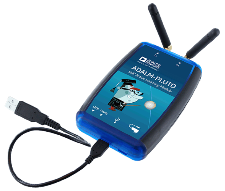
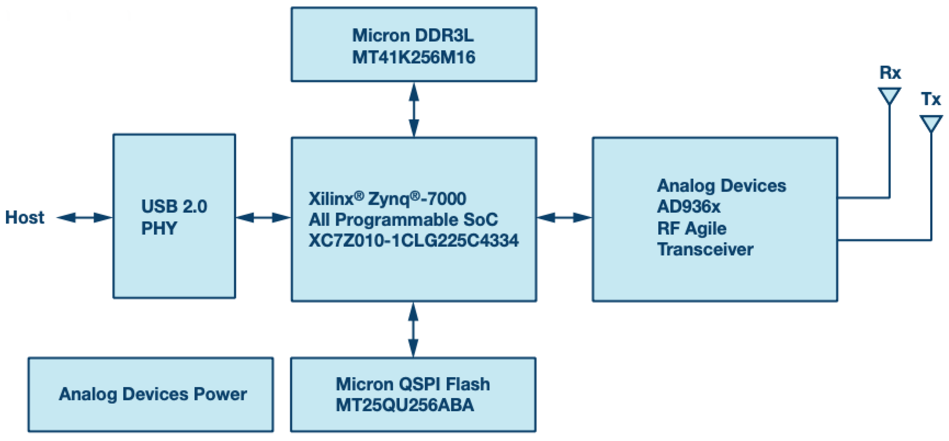
2.2. Analog Devices “ADALM-Pluto”

Keeping in mind the requirements of portability and adaptability to different soil conditions, set out in the previous paragraph, a comparative evaluation of the characteristics and performance of the devices on the market was made, which highlighted how the most suitable solutions, for the specific application, are those with integrated transceivers. What emerges from a first exploration is that devices with much more extensive functionality than our needs are available, which in most cases have only the radio-frequency section and requires additional control modules, vanishing the requirement of lightness and compactness necessary for the use of RADAR in portability. Furthermore, the overall cost of these products is high compared to the spending objectives and programming requires specific skills for the device, binding the software produced to the electronics implemented and therefore limiting the possibility of updating the system in relation to the level of TRL (Technology Readiness Level) reached.
Our attention then fell on Software Defined Radio technology (SDR) [28]. The SDR makes it possible to build radio equipment that is no longer strictly realized as hardware only, but based, or rather “defined” by means of software, in particular to manage the functions of modulation and demodulation of the signals and configuration of the hardware present. The SDR method allows us to obtain a re-programmable device, thus allowing to modify the device to implement new functions or to easily reconfigure the operating parameters [28]. There are many devices that implement SDR technology on the market. We have identified one by Analog Devices (Analog Devices Corporate Headquarters, One Analog Way, Wilmington, MA 01887, USA), called “Adalm Pluto”. Pluto ( Figure 5), this is the abbreviated name commonly used in the vast community of users on the Internet, is currently sold for USD 200. The large community on the network and the wide availability of technical support provided free of charge by Analog Devices, further enriches the value of the device.
Is designed to provide RF/SDR functionality to students and for them to be purchased at an affordable price. In Figure 6 its simplified internal architecture is illustrated; The radio section consists of the AD936x integrated device, this interfaces with a FPGA (Field Programmable Gate Array) Xilinx® Zynq® 7000 which, despite having limited resources (28,000 logic cells), allows to carry out part of the data processing internally. The available memory is divided into 512 MB DDR3 volatile memory and a 32 MB Flash ROM memory, intended to contain the programming of the device. The blocks are managed through a micro-controller of the ARM Cortex series®-A9 @ 667 MHz. The power supply is taken directly from the USB 2.0 interface.
A feature of this product is that it is part of a family of devices developed on a common platform. This means that it is possible to develop software for Pluto and then transfer it to higher performing devices or devices with more functions of the same family, as the prototype reaches higher levels of technological evolution.
Figure 7 illustrates the simplified receiver architecture. At the input there is an LNA (Low Noise Amplifier) and an I/Q demodulator, then there follows an analog to digital conversion section and then the signal enters a DSP module for any further processing. The transmitter has the same architecture in reverse. Compared with the architecture of the electronic of “RASCAN-5” you can see similarities, but with important differences. The first is that Pluto electronics are fully integrated and consequently smaller and less expensive than those built with discrete electronic components. Furthermore, fewer mechanical fixing points for the components and the short electrical connections between them without connectors and cables, makes the electronics more reliable in the presence of mechanical vibrations, when used outdoors. The second difference is in the electronic parameters, that are programmables. The third is the presence of a Digital Signal Processor (DSP) which allows, if necessary, to process the data samples, for example by applying a filter to reduce aliasing. Finally the flexibility of this programmable architecture permits us to avoid a synchronization with the spatial position of the RADAR antenna made by an encoder that physically act as trigger for the sampling. The synchronization is done after the acquisition of the samples, correlating them with the positions using a timestamp. This type of synchronization is reliable, does not require the knowledge of the path of the antenna and simplifies the electronics. A last noteworthy feature is that Pluto is a complete, light and very small-size system.
Table 1 is a summary table of all the main features.
The overall architecture of the designed RADAR for microwave images, with Adalm Pluto, is represented in the block diagram of Figure 8.

2.3. The Programming of Adalm Pluto

PlutoSDR users can interact with RF signals with MATLAB® and Simulink®, GNU Radio, or with custom software in C, C ++, C # or Python on x86 Windows, Linux or Mac host or embedded Linux platform (Raspberry Pi, Beaglebone, etc.) using USB communication. With programming, we can put PlutoSDR in different modes and support different external USB devices (such as LAN via USB or WiFi via USB), extending the capabilities of the device. It is also possible to write HDL code for the FPGA, which runs directly on PlutoSDR. We can compile HDL projects, compile kernels, and/or run custom user space applications.
In a first approach to the device we used Simulink, which allows us to use functional blocks for the transmitting and receiving section. In order to obtain greater speed in controlling the device and to be independent from the software development environment, it was necessary to switch to command line programming. Among the possible control modes of Pluto, intermediate between the use of frameworks and the actual programming of structured languages, such as C ++ or Python, there is the possibility of sending commands via shell. Pluto is controlled by instructions that belong to the IIO (Industrial Input Output) software library, which are described in the following section.

2.4. The Industrial Input-Output (Iio) Library

PlutoSDR runs Linux. The device drivers that allow you to control the transceiver and acquire samples are part of the Linux Industrial I/O (IIO) framework. IIO is a kernel subsystem for analog-to-digital or digital-to-analog converters and related hardware. IIO communicates with user space via “sysfs” filesystem and character device. From the point of view of the interaction with the user, this mode of communication is quite intuitive, since everything is just a file. However, when you want to control the device via software, this mode can be cumbersome, since you just want to call a function or method instead of doing string manipulation and file IO. The “LibIIO” library used by Pluto provides the abstraction layer of the device that allows to interface easily to IIO. LibIIO is cross-platform and usable by different programming languages, so you can control IIO devices from C, C ++, C # or Python.
LibIIO is therefore a library that has been developed to facilitate software interfacing with Linux Industrial I/O based devices. There are five main user space commands/utilities:
  • iio _attr: read and write IIO attributes
  • iio _info: download IIO attributes
  • iio _readdev: read a buffer of an IIO device
  • iio _writedev: write a buffer of an IIO device
  • iio _reg: read or write SPI or I2C registers in an IIO device (useful for debugging drivers)
Using these instructions, which can be sent to the device from the linux shell, it is possible to modify the parameters (attributes) of the hardware and software devices inside Adalm Pluto.

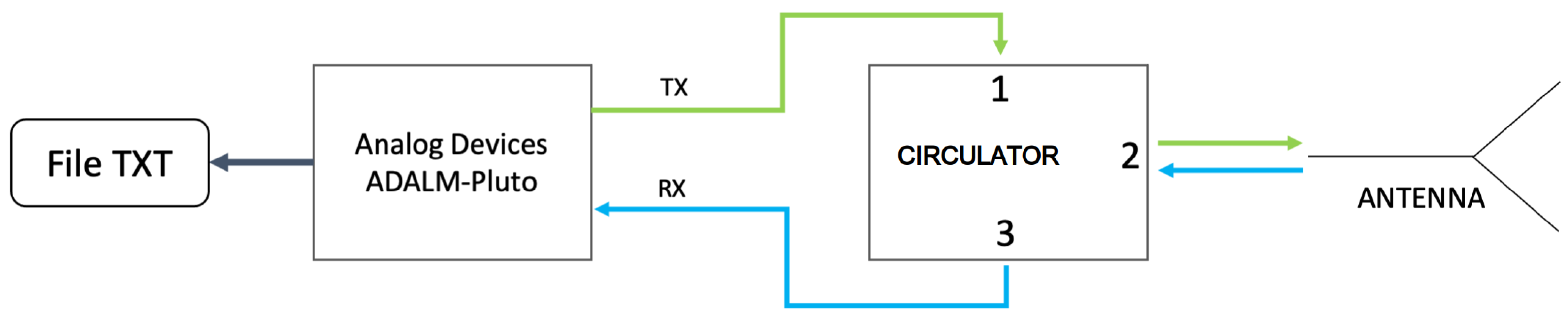
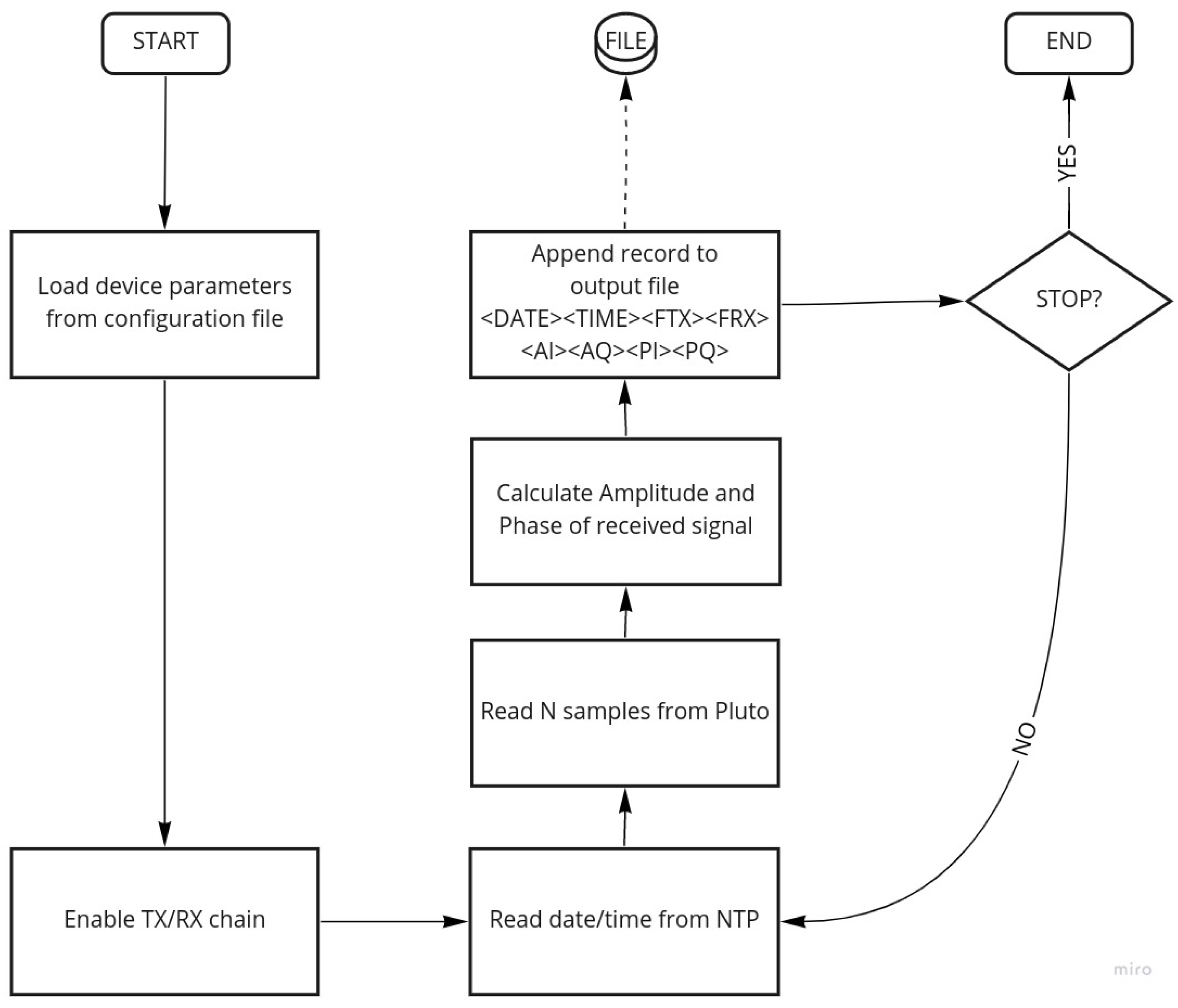
2.5. Radar Control Software

To automate the execution of the software and the setting of the parameters, a Bash script has been created whose block diagram is represented in Figure 9.
A script reads the configurable Pluto parameters from a text file and sets the IIO on the device. The configuration file allows us to set the following parameters:
  • IP address of the device
  • Transmit and receive amplifier gain [dB]
  • Carrier frequency [Hz]
  • Modulating sinusoid frequency [Hz]
  • baseband sampling rate [Hz]
  • Input low pass filter cutoff frequency [Hz]
  • Parameters related to the internal signal generator
The plutoScan.sh requires a command line parameter to be executed and the possible values of the parameter are:
  • “start”, start the acquisition
  • “stop”, it stops the acquisition and turns off the transmitter and receiver
  • “set <VARIABLE> <VALUE>”, set the value of variable in the configuration file
  • “view”, shows the configuration parameters
With the “start” command, the software sets the RADAR operating parameters consistently with the values indicated in the configuration file, switches on the radio frequency transmission and reception section and starts reading the sampled values for the In-phase and Quadrature components. The modulating signal transmitted is a 100 kHz sinusoidal signal translated in frequency in relation to the carrier frequency indicated in the configuration file. In reception, a 200 kHz band pass filter is applied, so the modulated frequency f M O D = 100 kHz is chosen to be at the center of the filter band.
Intuitively, it would be enough to transmit only the carrier, which will be modulated in amplitude by the interaction with the reflecting external environment. Adalm Pluto was not designed to transmit constant signals over time. We therefore decided to transmit a single tone, generated internally to the instrument (and therefore whose frequency and amplitude can be varied), which modulates the carrier in amplitude. In reception, therefore, we do not have a value for the I component and one for the Q component, but a sequence of samples of 100 kHz sinusoids. For extract the amplitude of the sinusoids, starting from the samples sequence I { i 1 , i 2 , , i N } and Q { q 1 , q 2 , , q N } , avoiding noise disturbance, we calculate the periodograms C I and C Q for I and Q [29]. The periodogram for a single tone ω = 2 π f M O D is the amplitude squared of the Discrete Fourier Transform (DFT) applied to the samples of the received signal (Equation (1)). The root of these periodograms are two squares amplitudes A I and A Q (Equation (3)). From these, we calculate the module and phase of the signal received by the RADAR (Equation (4)),
C I ( ω ) = 1 N R I ( ω ) 2 + I I ( ω ) 2 = 1 N j = 1 N i j e i ω t j 2 C Q ( ω ) = 1 N R Q ( ω ) 2 + I Q ( ω ) 2 = 1 N j = 1 N q j e i ω t j 2
were the R X and I X with X { I , Q } are
R x ( ω ) = n = 0 N 1 X n c o s ( ω t n ) I x ( ω ) = n = 0 N 1 X n s i n ( ω t n )
The amplitude of the sample is then calculated,
A I = C I , A Q = C Q
and with the amplitude of the components I and Q we can calculate the amplitude and phase of the received signal,
A = A I 2 + A Q 2 P = arctan A Q A I
The choice of the number of samples N of the received signal must be such as to allow obtaining a minimum number of periods to mediate any disturbances, however the more periods are acquired the greater the time necessary between one reading and the next. In the software configuration file it is possible to decide the value of a parameter, N C Y C L E S , which modifies the number of acquired samples according to the following relationship:
N S A M P = ( f S B B · N C Y C L E S / f M O D )
where f S B B is the baseband sampling frequency and f M O D the modulating frequency.
At 100 kHz, with the minimum available sampling frequency (2.1 MHz) and the parameter N C Y C L E S = 64 , as set by default in the software, N S A M P = 1344 is obtained, i.e., an overall acquisition time for each software cycle of 640 μ s, regardless of device latency and software execution. Considering an average speed value of 100 mm/s for the mechanical handling system, the theoretical minimum space traveled between two acquisitions is 64 μ m. For the slow velocity of the mechanical scan, we had evaluated that is not necessary to take in account the Doppler effect on the acquired data.
The software then reads the date and time, the latter with the detail in microseconds, and opens a text file in which they are stored. Consistently with the abbreviations used in the Figure 9 diagram:
  • <DATE>, the date
  • <TIME>, time in UTC (Coordinated Universal Time) format
  • <FTX>, carrier frequency to the transmitter
  • <FRX>, carrier frequency to the receiver
  • <AI> <AQ>, amplitude of the I and Q components
  • <PI>, <PQ> phase of components I and Q
The acquisition and writing process continues cyclically until the “stop” command is sent through the linux shell. At that point the PlutoSDR device is put on standby.

3. Results

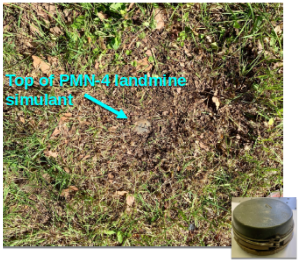
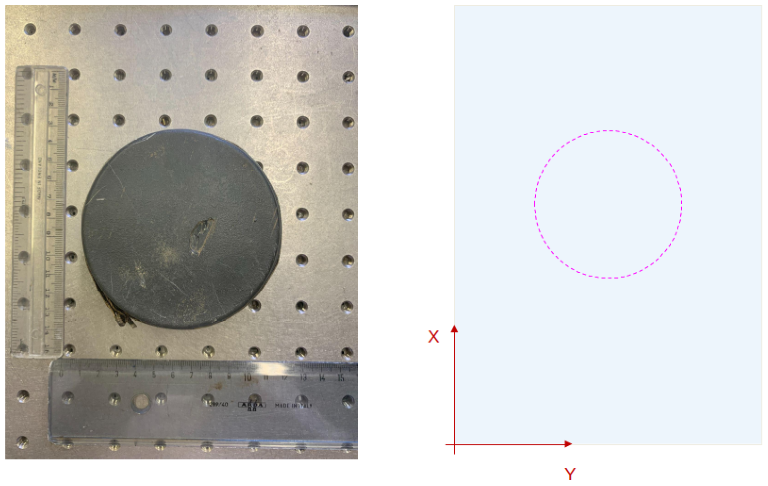
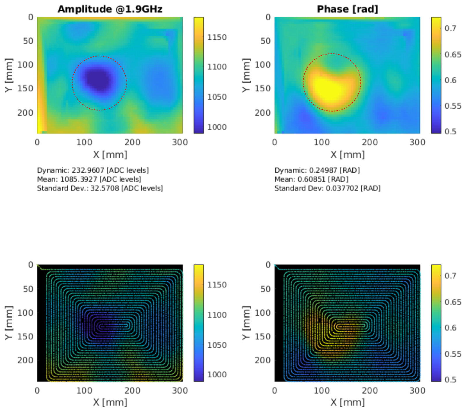
3.1. Description of Experimental Results

Thanks to the possibility to set the working electrical parameters by software, this RADAR is capable to observe the shape and dimensions of the objects buried in the first 15–20 cm of the subsoil with a resolution of 3 cm (according to the theory of optical holography. The lateral resolution of the system is ≈ λ 2 . In the terrain, considering a mean value of the dielectric permittivity ε r = 6 , the wave length λ 0.061 m) [13,30]. The holographic RADAR system designed as described in the previous section, can acquire a PMN-4 type anti-personnel mine. The mine has been buried in the ground about 5 cm deep for over four years. Figure 10 shows the buried mine after acquisition. In the left side of the Figure 11 is reported the optical reference of the mine. In the right side of the Figure 11 the position of the mine in the scanning surface. The mine is acquired at the frequency of 1.9 GHz, without attenuation on the transmission chain, corresponding to a power at the antenna input of 9.5 dBm and a gain of 10 dB on the reception chain of the Adalm PLUTO device. The bandwidth set to 200 kHz. A 100 kHz sinusoidal signal is used in this sweep and 64 periods are considered for amplitude and phase calculation. The received signal is sampled at 2.1 MHz, corresponding to the minimum sampling frequency of the device. These settings are resumed in the Table 2.
Figure 12 shows the acquisition with the synthetic aperture plane of the radar positioned 6 cm away from the ground plane. The RADAR for landmine detection, is designed to work in near field region. We can consider near field the distances r < λ with λ = 0.15 m in air @ 2 GHz. The two images above, show the amplitude of the received signal and the phase rotation with respect to the reference phase. The two images at the bottom of the same Figure represent the position of the samples acquired by the RADAR in the position of the space in which they were acquired. You can see the path made by the RADAR head during the scan. The landmine is inside the dashed circle.

3.2. Conclusions

The function for which this holographic RADAR was designed is the generation of microwave images of objects buried in the ground at shallow depth. To obtain this functionality, an architecture of the system electronics has been developed which makes the HSR easily installable on scanners moved on the ground by robotic platforms and, even more importantly, the programming of the operating parameters. The reconfigurability of the holographic RADAR allows to optimize the measurement chain largely defined by the characteristics of the antenna and the electromagnetic characteristics of the ground. Furthermore, by programming the scanning positions, the position of the scanning plane with respect to the ground floor can be optimized and may vary in relation to the morphology of the soil. The amplitude levels of the emitted signal (0 dBm to 9.5 dBm) can be adapted to avoid signal saturation due to the high reflectivity of the interface. Furthermore, thanks to the electronics architecture of the Adalm Pluto module, a high degree of versatility is achieved, for example the modification of the values of ADC sampling rate (2.1 MSPS to 61.44 MSPS), the bandwidth of the filters (0.2 MHz to 20 MHz), the carrier frequency (0.325 GHz to 6 GHz), gain of receiver (0 to 70 dB) and the possibility to generate arbitrary waveforms. To obtain these results, it was decided to identify a device based on the Software Defined Radio architecture that allows the use of integrated electronic components, and therefore more reliable, compact and versatile than the electronics architectures optimized to work with a specific band antenna. The architecture chosen, the Adalm Pluto device by Analog Devices, offers this possibility together with a contained volume and weight, an energy consumption compatible with the portable system on which the RADAR is installed and, another element that guided the choice, at a cost of less than USD 200. This device has a scalable architecture that guarantees to maintain the development work carried out even when the technological level of the prototype requires an upgrade to more performing devices. The software that has been developed allows, through a simple configuration file, to set all the operating parameters of the device. Furthermore, this architecture has allowed us to spatially correlate the samples acquired at various instants of time with the positions of the scanner by implementing an algorithm based on time stamp of the data. In general, the latter solution simplifies the integration of the holographic RADAR with mechanical scanning systems. This allows for greater flexibility of use of the system and greater acquisition speed.

Author Contributions

Conceptualization, L.B., P.F., L.C.; methodology, L.B., P.F., L.C.; software, L.B., P.F.; validation, L.B., P.F., L.C.; formal analysis, L.B., P.F.; investigation, L.B., P.F.; resources, L.B., P.F.; data curation, L.B., P.F.; writing—original draft preparation, L.B.; writing—review and editing, L.B., P.F., L.C.; supervision, L.C.; project administration, L.C.; funding acquisition, L.C. All authors have read and agreed to the published version of the manuscript.

Funding

This research was funded by NATO SPS G-5731 Project and Ente Cassa di Risparmio di Firenze “BIG DATA” project.

Data Availability Statement

Not applicable.

Acknowledgments

Thanks to NATO SPS for supporting the project G-5731 and the team involved in the project: University of Florence (Florence, Italy), Franklin and Marshall college (Lancaster, PA, USA), Usikov Institute (Karkiv, Ukraine), Jordan University of Science and Technology (Irbid, Jordan).

Conflicts of Interest

The authors declare no conflict of interest. The funders had no role in the design of the study; in the collection, analyses, or interpretation of data; in the writing of the manuscript; or in the decision to publish the results.

Abbreviations

The following abbreviations are used in this manuscript:
DOAJDirectory of open access journals
RADARRadio Detection And Ranging
HSRHolographic Sub-surface RADAR
GPRGround Penetrating RADAR
UWBUltra Wide Band
NATONorth Atlantic Threaty Organization
ERWExplosive Remnants of War
IEDImprovised Explosive Devices
UXOUneXploded Devices
SoCSystem On a Chip
SDRSoftware Defined Radio
NTPNetwork Time Protocol
I/QComponenti in fase (I) e quadratura (Q) di un segnale
CWContinuos Wave
FPGAField Programmable Gate Array
RAMRandom Access Memory
USBUniversal Serial Bus
CPUCentral Processing Unit
LNALow Noise Amplifier
DDSDirect Digital Synthesis
VCOVoltage Controlled Oscillator
ADCAnalog to Digital Converter
DACDigital to Analog Converter

References

  1. Landmine and Cluster Munition Monitor | Monitor. Available online: http://www.the-monitor.org/en-gb/home.aspx (accessed on 11 September 2022).
  2. Ursign Hofmann (GICHD); Olaf Juergensen (UNDP). Leaving No One Behind: Mine Action and the Sustainable Development Goals; Geneva International Centre for Humanitarian Demining (GICHD)—United Nations Development Programme (UNDP): Geneva, Switzerland, 2017. [Google Scholar]
  3. Capineri, L.; Pochanin, G.; Bechtel, T.; Lande, T.S.; Capan, I.; Pastuovic, Z.; Ohshima, T.; Coutinho, J.; Snoj, L.; Palucci, A.; et al. NATO Advanced Research Workshop on Explosives Detection. In Explosives Detection; Capineri, L., Turmuş, E.K., Eds.; NATO Science for Peace and Security Series B: Physics and Biophysics; Springer: Dordrecht, The Netherlands, 2019; pp. 1–32. [Google Scholar] [CrossRef]
  4. Pochanin, G.; Capineri, L.; Bechtel, T.; Ruban, V.; Falorni, P.; Crawford, F.; Ogurtsova, T.; Bossi, L. Radar Systems for Landmine Detection: Invited Paper. In Proceedings of the 2020 IEEE Ukrainian Microwave Week (UkrMW), Kharkiv, Ukraine, 22–27 June 2020; pp. 1118–1122. [Google Scholar] [CrossRef]
  5. Cardona, L.; Jiménez, J.; Vanegas, N. Landmine Detection Technologies to Face the Demining Problem in Antioquia. DYNA 2014, 81, 115. [Google Scholar] [CrossRef]
  6. Furuta, K.; Ishikawa, J. (Eds.) Anti-Personnel Landmine Detection for Humanitarian Demining: The Current Situation and Future Direction for Japanese Research and Development; OCLC: ocn315067154; Springer: New York, NY, USA; London, UK, 2009. [Google Scholar]
  7. Ivashov, S. Wide-span systems of mine detection. In Proceedings of the Second International Conference on Detection of Abandoned Land Mines, Edinburgh, UK, 12–14 October 1998; Volume 1998, pp. 78–80. [Google Scholar] [CrossRef]
  8. Daniels, D.J.; Daniels, D.J.; Institution of Electrical Engineers (Eds.) Ground Penetrating Radar, 2nd ed.; Number 15 in IEE Radar, Sonar, Navigation, and Avionics Series; OCLC: ocm56442546; Institution of Electrical Engineers: London, UK, 2004. [Google Scholar]
  9. Borgioli, G.; Bossi, L.; Capineri, L.; Falorni, P.; Bechtel, T.; Crawford, F.; Inagaki, M.; Pochanin, G.; Ruban, V.; Varyanitza-Roschupkina, L.; et al. A Hologram Reconstruction Algorithm for Landmine Recognition and Classification Based on Microwave Holographic Radar Data. In Proceedings of the 2018 Progress in Electromagnetics Research Symposium (PIERS-Toyama), Toyama, Japan, 1–4 August 2018; pp. 1938–1944. [Google Scholar] [CrossRef]
  10. Sato, M. Dual Sensor ALIS for Humanitarian Demining and its Evaluation Test in Mine Fields in Croatia. In Proceedings of the IGARSS 2008-2008 IEEE International Geoscience and Remote Sensing Symposium, Boston, MA, USA, 6–11 July 2008; pp. II-181–II-184. [Google Scholar] [CrossRef]
  11. Iizuka, K. Microwave hologram by photoengraving. Proc. IEEE 1969, 57, 813–814. [Google Scholar] [CrossRef]
  12. Iizuka, K.; Gregoris, L.G. Application of Microwave Holography in the Study of the Field from a Radiating Source. Appl. Phys. Lett. 1970, 17, 509–512. [Google Scholar] [CrossRef]
  13. Ivashov, S.I.; Razevig, V.V.; Vasiliev, I.A.; Zhuravlev, A.V.; Bechtel, T.D.; Capineri, L. Holographic Subsurface Radar of RASCAN Type: Development and Applications. IEEE J. Sel. Top. Appl. Earth Obs. Remote Sens. 2011, 4, 763–778. [Google Scholar] [CrossRef]
  14. Sahli, H.; Bottoms, A.M.; Cornelis, J.; EUDEM2 (Project); Society for Counter Ordnance Technology; Vrije Universiteit Brussel (Eds.) EUDEM2-SCOT, 2003, Proceedings of the International Conference on Requirements and Technologies for the Detection, Removal and Neutralization of Landmines and UXO, Brussels, Blegium, 15–18 September 2003; OCLC: 500237233; Vrije Universiteit Brussel: Brussels, Blegium, 2003. [Google Scholar]
  15. Capineri, L.; Arezzini, I.; Calzolai, M.; Windsor, C.G.; Inagaki, M.; Bechtel, T.D.; Ivashov, S.I. High Resolution Imaging with a Holographic Radar Mounted on a Robotic Scanner. In Proceedings of the Electromagnetics Research Symposium Proceedings, Stockholm, Sweden, 12–15 August 2013. [Google Scholar]
  16. Song, X.J.; Su, Y.; Huang, C.L.; Lu, M.; Zhu, S.P. Landmine detection with holographic radar. In Proceedings of the 2016 16th International Conference on Ground Penetrating Radar (GPR), Hong Kong, China, 13–16 June 2016; pp. 1–4. [Google Scholar] [CrossRef]
  17. Bossi, L.; Falorni, P.; Priori, S.; Olmi, R.; Capineri, L. Numerical Design and Experimental Validation of a Plastic 3D-Printed Waveguide Antenna for Shallow Object Microwave Imaging. Sens. Imaging 2021, 22, 22. [Google Scholar] [CrossRef]
  18. Bechtel, T.; Truskavetsky, S.; Capineri, L.; Pochanin, G.; Simic, N.; Viatkin, K.; Sherstyuk, A.; Byndych, T.; Falorni, P.; Bulletti, A.; et al. A survey of electromagnetic characteristics of soils in the Donbass region (Ukraine) for evaluation of the applicability of GPR and MD for landmine detection. In Proceedings of the 2016 16th International Conference on Ground Penetrating Radar (GPR), Hong Kong, China, 13–16 June 2016; pp. 1–6. [Google Scholar] [CrossRef]
  19. DEMINING ROBOTS. Available online: http://www.natospsdeminingrobots.com (accessed on 11 September 2022).
  20. Bossi, L.; Falorni, P.; Pochanin, G.; Bechtel, T.; Sinton, J.; Crawford, F.; Ogurtsova, T.; Ruban, V.; Capineri, L. Design of a robotic platform for landmine detection based on Industry 4.0 paradigm with data sensors integration. In Proceedings of the 2020 IEEE International Workshop on Metrology for Industry 4.0 & IoT, Roma, Italy, 3–5 June 2020; pp. 16–20. [Google Scholar] [CrossRef]
  21. Bechtel, T.; Gennadiy, P.; Vadym, R.; Tetiana, O.; Orlenko, O.; Pochanina, I.; Kholod, P.; Lorenzo, C.; Pierluigi, F.; Bulletti, A.; et al. Application of the Industry 4.0 paradigm to the design of a dual GPR system for Humanitarian Demining. FASTTIMES 2019, 24, 112–120. [Google Scholar]
  22. Bossi, L.; Falorni, P.; Capineri, L. Performance comparison for the detection of defects in thermal insulating materials using microwave holograms acquired manually and with a robotized scanner. J. Electromagn. Waves Appl. 2019, 33, 2081–2095. [Google Scholar] [CrossRef]
  23. Capineri, L.; Zandonai, F.; Inagaki, M.; Razevig, V.; Ivashov, S.; Windsor, C.; Bechtel, T. RASCAN holographic radar for detecting and characterizing dinosaur tracks. In Proceedings of the 2013 7th International Workshop on Advanced Ground Penetrating Radar, Nantes, France, 2–5 July 2013; pp. 1–6. [Google Scholar] [CrossRef]
  24. Amineh, R.K.; Ravan, M.; Sharma, R.; Baua, S. Three-Dimensional Holographic Imaging Using Single Frequency Microwave Data. Int. J. Antennas Propag. 2018, 2018, 6542518. [Google Scholar] [CrossRef]
  25. Sheen, D.; McMakin, D.; Hall, T. Three-dimensional millimeter-wave imaging for concealed weapon detection. IEEE Trans. Microw. Theory Tech. 2001, 49, 1581–1592. [Google Scholar] [CrossRef]
  26. Amineh, R.K.; Ravan, M.; Khalatpour, A.; Nikolova, N.K. Three-Dimensional Near-Field Microwave Holography Using Reflected and Transmitted Signals. IEEE Trans. Antennas Propag. 2011, 59, 4777–4789. [Google Scholar] [CrossRef]
  27. Ravan, M.; Amineh, R.K.; Nikolova, N.K. Two-dimensional near-field microwave holography. Inverse Probl. 2010, 26, 055011. [Google Scholar] [CrossRef]
  28. Collins, T.F.; Getz, R.; Pu, D.; Wyglinski, A.M. Software-Defined Radio for Engineers; Artech House Mobile Communications Series; Artech House: Norwood, MA, USA, 2018. [Google Scholar]
  29. Bretthorst, G.L. Bayesian Spectrum Analysis and Parameter Estimation; OCLC: 1159219355; Springer International Publishing: Berlin/Heidelberg, Germany, 1988. [Google Scholar]
  30. Bossi, L. A Novel Microwave Imaging RADAR for Anti-Personnel Landmine Detection and Its Integration on a Multi-Sensor Robotic Scanner; FLORE Università degli Studi di Firenze: Firenze, Italy, 2022. [Google Scholar]
Figure 1. Methods and technolgies for GPR (Ground Penetrating RADAR).
Electronics 11 02883 g001
Figure 2. Block diagram of RASCAN-5 electronic architecture.
Electronics 11 02883 g002
Figure 3. Block diagram of the electronics for a microwave processing the signal of a MW HSR.
Electronics 11 02883 g003
Figure 4. Illustration of the geometry of holographic acquisition. In blue the holographic RADAR antenna that is moved by the mechanical scanning frame (not illustrated) on the scanning plane (dashed pink rectagle) on fixed positions (a grid of 5 mm step).
Electronics 11 02883 g004
Figure 5. Picture of the “Adalm-PLUTO” SDR device produced by Analog Devices; The image shows the programming and access connector (USB) and the two supplied antennas installed.
Electronics 11 02883 g005
Figure 6. Block diagram representative of the internal architecture of the “Adalm-PLUTO” device.
Electronics 11 02883 g006
Figure 7. Representative block diagram of the internal architecture of the receiver in the “Adalm-PLUTO” device.
Electronics 11 02883 g007
Figure 8. Block diagram of the operating principle of the holographic microwave RADAR with integrated electronics.
Electronics 11 02883 g008
Figure 9. Flow chart of the “plutoScan.sh” software that allows us to control the RADAR for microwave images.
Electronics 11 02883 g009
Figure 10. Image of PMN4 type landmine after acquisition. The over four-years-buried mine top is visible after removal of above terrain. Photo taken in the garden of the School of Engineering of University of Florence.
Electronics 11 02883 g010
Figure 11. On the left: optical reference of PMN4 landmine. The size is 11 cm diameter, 8 cm height. On the right: the representation of the scanning area (33 cm × 17 cm) and the mine position.
Electronics 11 02883 g011
Figure 12. Acquisition of PMN4 landmine buried in the soil. On the top, amplitude and phase—referred to the phase of the transmitted signal. On the bottom, the position of the samples in the scanning plane. The path followed by the antenna is visible.
Electronics 11 02883 g012
Table 1. Main specifications of Analog Devices ADALM Pluto.
Main SpecificationsTypical
DC Input4.5 V to 5.5 V
ADC and DAC sample rate65.2 kSPS to 61.44 MSPS
ADC and DAC resolution12 bit
Tuning range325 MHz up to 6 GHz
TX power output7 dBm
Interface and powerUSB 2.0
FPGA logic cells28k
DSP slices80
Dimensions117 mm × 79 mm × 24 mm
Weight114 g
Table 2. Acquisition settings for the presented results.
ParameterValue
Carrier frequency1.9 GHz
Frequency of the modulating tone100 kHz
Power at the antenna input9.5 dBm
Attenuation on the TX chain−3 dB
Gain on the RX chain10 dB
TX and RX bandwidth filter settings200 kHz
Baseband sampling rate2.1 MHz
Number of acquired cycles ( N C Y C L E S )64
Publisher’s Note: MDPI stays neutral with regard to jurisdictional claims in published maps and institutional affiliations.

