Review

A Survey on CubeSat Missions and Their Antenna Designs

by
Sining Liu
1,
Panagiotis Ioannis Theoharis
1,
Raad Raad
1,
Faisel Tubbal
1,2,*,
Angelos Theoharis
1,3,
Saeid Iranmanesh
1,
Suhila Abulgasem
1,
Muhammad Usman Ali Khan
1,4 and
Ladislau Matekovits
5,6,7
1
School of Electrical, Computer and Telecommunications Engineering, University of Wollongong, Wollongong, NSW 2522, Australia
2
Technological Projects Department, The Libyan Center for Remote Sensing and Space Science, Tripoli 21218, Libya
3
Department of Electronics, Information and Bioengineering, Politechnico di Milano, 20125 Milan, Italy
4
Department of Electronic Engineering, The Islamia University of Bahawalpur, Bahawalpur 63100, Punjab, Pakistan
5
Department of Electronics and Telecommunications, Politecnico di Torino, 10129 Turin, Italy
6
Istituto di Elettronica e di Ingegneria dell’Informazione e delle Telecomunicazioni, National Research Council, 10129 Turin, Italy
7
Department of Measurements and Optical Electronics, Politehnica University Timisoara, 300006 Timisoara, Romania
*
Author to whom correspondence should be addressed.
Electronics 2022, 11(13), 2021; https://doi.org/10.3390/electronics11132021
Submission received: 1 June 2022 / Revised: 20 June 2022 / Accepted: 22 June 2022 / Published: 27 June 2022
(This article belongs to the Special Issue Antenna Designs for 5G/IoT and Space Applications)

Abstract

:
CubeSats are a class of miniaturized satellites that have become increasingly popular in academia and among hobbyists due to their short development time and low fabrication cost. Their compact size, lightweight characteristics, and ability to form a swarm enables them to communicate directly with one another to inspire new ideas on space exploration, space-based measurements, and implementation of the latest technology. CubeSat missions require specific antenna designs in order to achieve optimal performance and ensure mission success. Over the past two decades, a plethora of antenna designs have been proposed and implemented on CubeSat missions. Several challenges arise when designing CubeSat antennas such as gain, polarization, frequency selection, pointing accuracy, coverage, and deployment mechanisms. While these challenges are strongly related to the restrictions posed by the CubeSat standards, recently, researchers have turned their attention from the reliable and proven whip antenna to more sophisticated antenna designs such as antenna arrays to allow for higher gain and reconfigurable and steerable radiation patterns. This paper provides a comprehensive survey of the antennas used in 120 CubeSat missions from 2003 to 2022 as well as a collection of single-element antennas and antenna arrays that have been proposed in the literature. In addition, we propose a pictorial representation of how to select an antenna for different types of CubeSat missions. To this end, this paper aims is to serve both as an introductory guide on CubeSats antennas for CubeSat enthusiasts and a state of the art for CubeSat designers in this ever-growing field.

1. Introduction

CubeSats are a type of spacecraft called miniaturized satellites that are categorized based on their size, namely minisatellites, microsatellites, nanosatellites, picosatellites, and femtosatellites [1]. CubeSats belong to the class of nanosatellites having the smallest dimensions of 10 cm × 10 cm × 10 cm (1U) and a mass of 1.3 kg. As shown in Figure 1, other available sizes range from 2U up to 12U with a mass of 15.6 kg. In addition, Table 1 shows the weight and dimensions of the CubeSats in each category. However, nanosatellites of less than 1 kg have yet to be designed for commercial applications [2].
Having such small and light features enables developers to provide a time- and cost-effective solution to designing fully functional satellites. The development cost is significantly less than standard satellite missions, as CubeSats can be launched as a secondary payload from standardized ejection modules such as the Poly-Picosatellite Orbital Deployer (P-POD) [3] or being deployed from the International Space Station [4]. The original reference of CubeSat design specifications dates back to 1999, when it was proposed by professors Jordi Puig-Suari from California Polytechnic State University and Bob Twiggs from Stanford University. These specifications, including mechanical, electrical, operational, and testing requirements, set the foundations for CubeSat design [5,6]. By referring to the maturing standards gradually developed over the years, a CubeSat mission can be finished within a few years.
The primary goal of introducing this new class of satellites was to educate graduate students on developing skills for designing, building, testing, and operating small satellites in low Earth orbit (LEO) and developing new scientific research methods, as well as advancing new space technologies. Meanwhile, the first CubeSat mission was launched in 2003, and only a handful of CubeSats were launched every year before 2013. As mentioned, this is because most CubeSats were developed by universities or research institutions. The number of CubeSat missions increased rapidly only when commercial applications joined the field [7]. To date, many CubeSats have been designed, launched, and operated successfully at low Earth orbit (LEO). Examples include CanX-1, CUTE-1, and AUU [8]. Very few CubeSats are designed, launched, and operated for deep space communications, such as those in [9,10]. On the other hand, CubeSats have limited functionality compared with other larger in size satellites. For instance, fitting an on-board propulsion system [11], large solar panels [12], radiators [13], as well as high-gain antennas [14] has proven to be a series of challenging tasks due to the limited room on the CubeSat [15]. However, the advancements in printed circuit board (PCB) technology [16,17] and the availability of off-the-shelf components (COTS) alongside the development of more powerful processors such as Field Programmable Gate Arrays (FPGAs) [18] have enabled researchers to develop cost-effective CubeSats for various challenging missions.
One of the key challenges is an antenna design that achieves a high gain while having a small size. This is because higher gain leads to a higher data rate. However, the higher the gain, the more highly directional it is. This means the CubeSat’s antenna must be pointed with high accuracy toward the ground station to communicate at a high rate over the highly focused radio signal. According to the recent surveys in [19,20,21], most CubeSat missions use UHF bands typically at 438 MHz, with possible data rates of up to 9.6 kbps. While only CubeSats employ higher frequency bands such as S-band to increase the data rates, considering the data rates for a standard mobile phone, 9.6 kbps is indeed a throwback to another era. This issue has also been raised by NASA’s investigator Doug Rowland [22]. In addition, the orbital lifetime of CubeSat is another limitation, which is 0–100 days when it is orbiting at lower than 300 km. Higher altitudes might lead to an extended lifetime of up to 2 years at 400 km [23].
This paper is organized as follows. CubeSats and their subsystems are introduced in Section 2. The background on CubeSat antennas and several restrictions posed by the CubeSat standards are presented in Section 3. Furthermore, Section 3 reviews 120 CubeSat missions dating from 2003 to 2022 and draws conclusions on the mission type, frequency bands, and antenna type popularity among the CubeSat community. In Section 4, single-element antennas for CubeSat are presented, while in Section 5, antenna arrays and arraying techniques for CubeSats are reviewed. Section 6 presents a comparison between single-element antennas and antenna arrays. The paper concludes with Section 7, which includes the proposed pictorial representation of how to select an antenna for different types of CubeSat missions.

2. Background on CubeSats and Their Subsystems

Compared with conventional large and medium satellites, CubeSats weigh less and require less time for development (e.g., 1 year) [24]. Because of their limited size and weight, several restrictions should be considered in the design of a CubeSat system. The development of CubeSats has enabled the study and testing of novel ideas in the field of low-power microelectronics, digital signal processing, and communication protocols in space without spending millions of dollars. This section provides an overview of CubeSats.

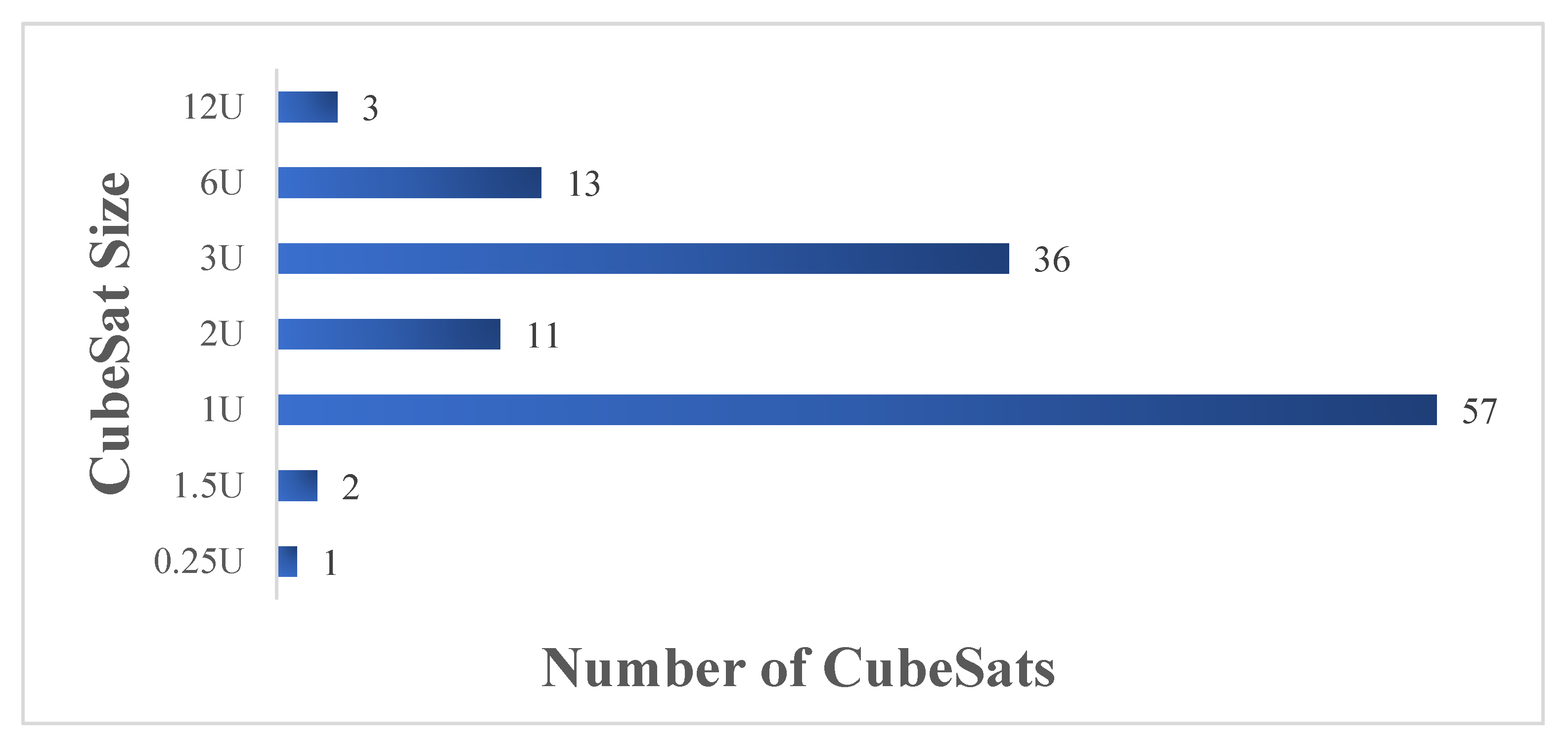
2.1. Mass and Volume

A small satellite often has limited room for the installation of electronics, antennas, payload, and solar panels. More specifically, large-volume antennas that generally have complex deployable systems are more likely to be excluded from a CubeSat mission. Thus, smaller antennas are preferable as they occupy small space on the CubeSat. Another important factor that influences the antenna’s choice and design for CubeSat missions is the mass. A typical CubeSat should weigh around 1.3 kg. Therefore, the weight of the antenna should be considered along with the different major weight contributions from the payloads, solar panels, core processors, batteries, and the chassis of the CubeSat. Failure to meet the CubeSat standards in terms of mass limitations would result in failure to launch.

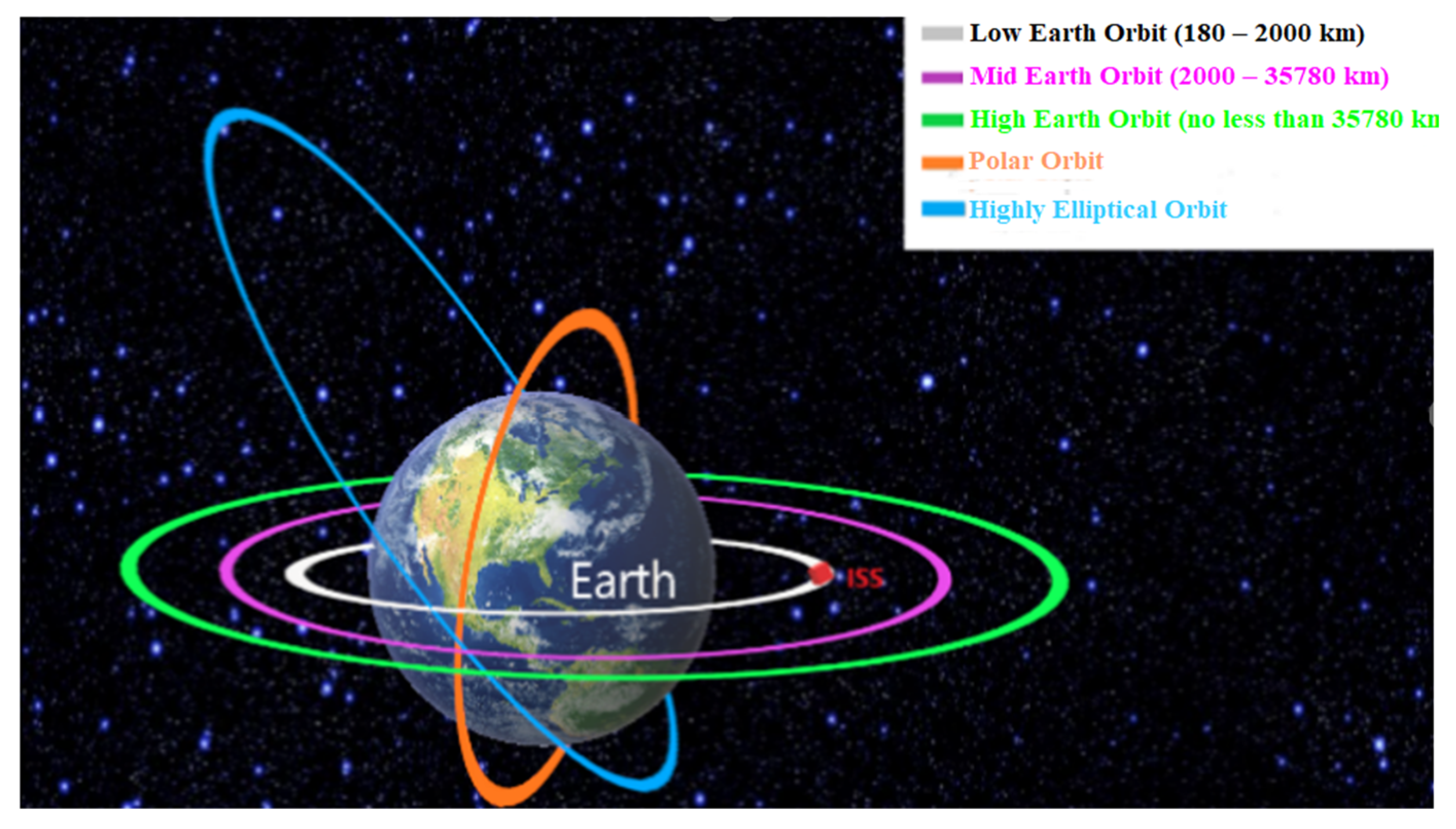
2.2. Low Earth Orbit (LEO)

Most CubeSat missions take place on LEO, which ranges from about 150 km up to approximately 600 km and is below the ionosphere. Within this region, there are many science satellites and the International Space Station (ISS) [25]. When orbiting in LEO, a CubeSat undergoes different heat inputs and passes through different light ranges. The antenna might be designed to radiate certain amounts of power, but it should also be designed accordingly to reject any power received from unwanted sources. The noise temperature is a parameter which should be considered and modelled properly when designing an antenna for space missions where the thermal environment is harsh. For example, Earth can be considered an ideal blackbody in equilibrium that absorbs all the electromagnetic energy and emits energy at the same rate, which implies that Earth is an unwanted power source for the antenna. These fluctuations in the external space environment should be considered when designing a CubeSat. Figure 2 shows the altitude classifications for geocentric orbits.

2.3. Electrical Power Subsystem (EPS)

Another essential part for the satellite subsystems is the power subsystem, which constantly supplies the required power during the operation of the CubeSat. Power budgeting is one of the primary objectives of the CubeSat’s design, and it must follow accurate calculations and obey certain limitations. Solar power is the main source of CubeSat power, since sunlight is the only available energy source in space. Other extra energy sources such as fuel cells and radioactive decay units are not practical for CubeSats. The expected power usage of the CPU, the radio, and the sensors need to be predictable and tightly defined. An optimized scheme of power budgeting needs to be developed accordingly.
Many CubeSats use 5-V buses as their core components of the power system, as a 5-V microcontroller is common and popular. A voltage of 3.3 V is becoming increasingly popular for CubeSats as well. According to [26], the capacity of space-grade lithium polymer batteries in CubeSat applications can range from 1.1 Ah to 1.4 Ah among different suppliers. The authors of [27] presented a design for a CubeSat bus that can provide 1.3 W of power to support some kinds of Earth observation missions and makes an allocation of the power budget to each subsystem.

2.4. Command and Data Handling Subsystem (C&DH)

The main processor subsystem, also known as Command and Data Handling (D&DH), coordinates complex actions taken by different parts within the system and provides stable and synchronized operation. The main processor of a CubeSat needs to be small and consume a low amount of power. Most current CubeSat missions use microcontrollers, but microprocessors are being considered for future missions. Some common processors such as ARMA, PC-104, and H8S-2674R have been chosen for some CubeSat missions [28,29,30]. Processors such as the PIC series and AT91SAM series are also available from providers, namely Pumpkin and Tyvak, and have also been applied in this kind of small satellite project. Additionally, applications of BasicX-24 and Arduino as the main processors of CubeSats are compared in [31]. FPGAs are also an attractive solution for CubeSat C&DHs as they offer in-obit reconfiguration, and their fabric can be designed to be tailored to specific mission requirements [17].

2.5. Propulsion Subsystem

CubeSats may use propulsion systems to realize active attitude control, reaction wheel desaturation, drag recovery, orbit changes and proximity operations [32]. In addition, a proper propulsion system can help a CubeSat slow down orbital decay and extend its lifetime. Because of the restrictions on CubeSats, their propulsion systems can only be used on specific occasions. The following technologies have been applied on current CubeSat missions: solar sail, cold gas, electric propulsion systems, and chemical propulsion systems [33]. The design of propulsion systems is still being developed to push the capabilities of CubeSats even further.

2.6. Attitude Determination and Control Subsystem (ADCS)

The ADCS for CubeSats is responsible for controlling the orientation of the spacecraft from the current attitude to a desired one. Various sensors or gyroscopes are used to record the orientation. For example, magnetic coils and reaction wheels are applied to provide necessary torques to reorient the satellite. Generally, two types of stabilization methods are utilized, namely spin stabilization and three-axis stabilization. Spin-stabilization requires one of the satellite axes to be fixed toward a specific direction, and then the body of the satellite is rotated accordingly. For this method, an initial force will be applied to the body of the satellite around an axis, and then the satellite will keep rotating because of the moment of inertia in space. Secondly, with three-axis stabilization, a satellite can be reoriented and stabilized in three different orthogonal axes instead of spinning around one axis, which results in maintaining a fixed attitude relationship with Earth or a successful inter-satellite link, respectively [34].

3. Background on Antennas and CubeSat Missions

An antenna or an aerial is defined as an element that is capable of sending and receiving radio waves (IEEE Std 124-1983). Technically, antennas may be resonant or non-resonant devices and operate efficiently when their geometry and impedance characteristics are tuned to a specific frequency. Antennas direct energy in a specific direction (or in all directions) and do not add or subtract power to a transmitted or received signal. An ideal transmitting antenna is one that radiates power without reflecting energy back to the feeding circuit. An ideal receiving antenna is one that absorbs the entire incidence electromagnetic wave without reflection.
Antennas can be classified by their radiation pattern as isotropic, omnidirectional, or directional. An isotropic antenna is an ideal reference and not physically feasible since it has equal radiation in all directions. Omnidirectional antennas, or whip antennas, have equal radiation in a given plane (e.g., the horizontal plane), and radiation is reduced outside that plane. Usually, single-element antennas have a wide radiation pattern and relatively low gain, making them suitable for general communication purposes, where the location of the receiver or transmitter is unknown, while at the same time, they are less efficient for applications that require long-distance, reliable, and effective communication links. The most common antenna used on a CubeSat is a whip antenna, which is a single-element monopole antenna. In [30], a CubeSat with two whip antennas of different lengths is shown. It consists of a flexible wire where the bottom part is connected, usually through a coaxial feed to the receiver or transmitter, and typically mounted above a ground or metal plane. A popular whip antenna is a λ 4 monopole, where λ is referred to as the resonant wavelength. The length of the antenna L in meters can be calculated with Equation (1):
L = λ 4 = 300 4 f
where λ is the wavelength and f is the operating frequency in MHz. In a typical CubeSat application where the operating frequency is 433 MHz, a quarter-wavelength whip antenna should be 17.3 cm. However, this length exceeds the available CubeSat surface area. In this case, the antenna needs to be folded or rolled, stowed within the CubeSat body, and then deployed to its functional size after launch. This adds to the design complexity, as it brings in a potential point of failure for an antenna deployment mechanism. If the size is reduced, the antenna will be less efficient at the operating frequency. This simple example illustrates at least one design consideration when looking at the communication and antenna subsystem of a CubeSat.
On the other hand, directional antennas could radiate a relatively higher amount of power in specific directions and thus are more suitable than omnidirectional antennas when a higher gain is desirable. Realizing a directional radiation pattern can be accomplished by employing antenna arrays, reflectarrays, parabolic reflector antennas, horn antennas, or inflatable antennas. For example, in the case of antenna or phased arrays, the radiation fields from the elements of the array interfere constructively in the desired direction while cancelling each other out in other directions. Therefore, antenna arrays can synthesize a variety of radiation patterns which can be accurately pointed in the desired direction. As a result, higher data rate links can be established through higher signal-to noise-ratios (SNRs) and larger bandwidths (B). In short, antenna arrays have the following advantages. First, they have higher gain compared with single-element antennas and a better trade-off between antenna size and performance. Secondly, arrays can enable an electronically steerable beam with appropriate feeding of the elements. This can make satellites more versatile. Indeed, instead of physically reorienting a CubeSat to establish a link, its antenna beam can be electronically steered. Finally, they are more flexible in terms of mission-specific synthesis, as additional elements can be added when the mission needs a larger aperture or finer beam control, and the failure of a single element may not significantly impact the overall system’s performance.
Other methods that have been proposed to increase the overall CubeSat downlink capacity are known as CubeSat swarms or constellations [35]. As demonstrated in [34], a CubeSat swarm is a group of individual CubeSats working cooperatively and sharing resources with each other. Interestingly, a subset of CubeSats can form a virtual antenna array to realize a larger aperture area with higher reliability. As a result, the power, memory, and bandwidth can be shared and distributed inside the swarm. However, a swarm of CubeSats requires reliable and efficient inter-CubeSat communication links [36,37]. Specifically, high-speed inter-satellite links will help to facilitate formation-flying missions, where CubeSats maintain the desired relative separations, positions, and orientations. Omni-directional antennas are the first choice for inter-satellite links because they can easily respond to the constant reorienting or repositioning of CubeSats.

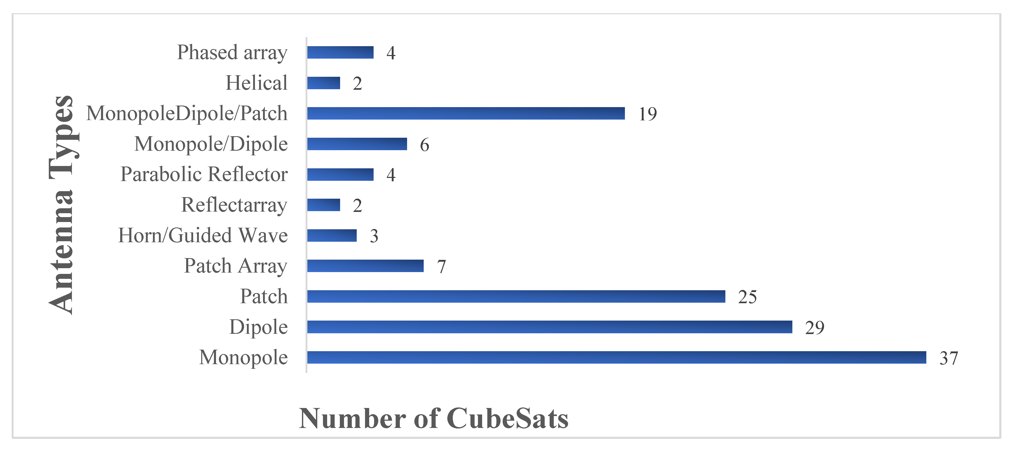
3.1. CubeSat Antenna Specifications

Antenna design is a complex task and must be tailored to the CubeSat mission under consideration. A CubeSat’s typical operation is performed in the VHF, UHF, or S-band, and the antennas are placed on one of the CubeSat surfaces. The size of a monopole or dipole antenna designed to operate in the VHF or UHF band usually exceeds a CubeSat’s surface, which is 10 cm × 10 cm. From this point of view, when designing antennas for CubeSat missions, the following concept should be followed: reduce the physical size of the antenna but maintain the desired radiation performance to meet the mission requirements. Telemetry, tracking and command, a high-speed downlink for payload data, GPS and GNSS signal reception, and inter-satellite communication links are some of the fundamental functions performed by the antenna system. In order to design CubeSat antennas for high-level missions, such as inter-satellite communications for distributed CubeSat swarms, it is necessary to properly define the specifications based on the communications requirements and the platform or mission aspects [38]. A summary of the restrictions posed by the CubeSat platform and their corresponding descriptions are presented in Table 2. These restrictions must be considered by the CubeSat antenna designer during the design and integration phase of the antenna with the CubeSat.

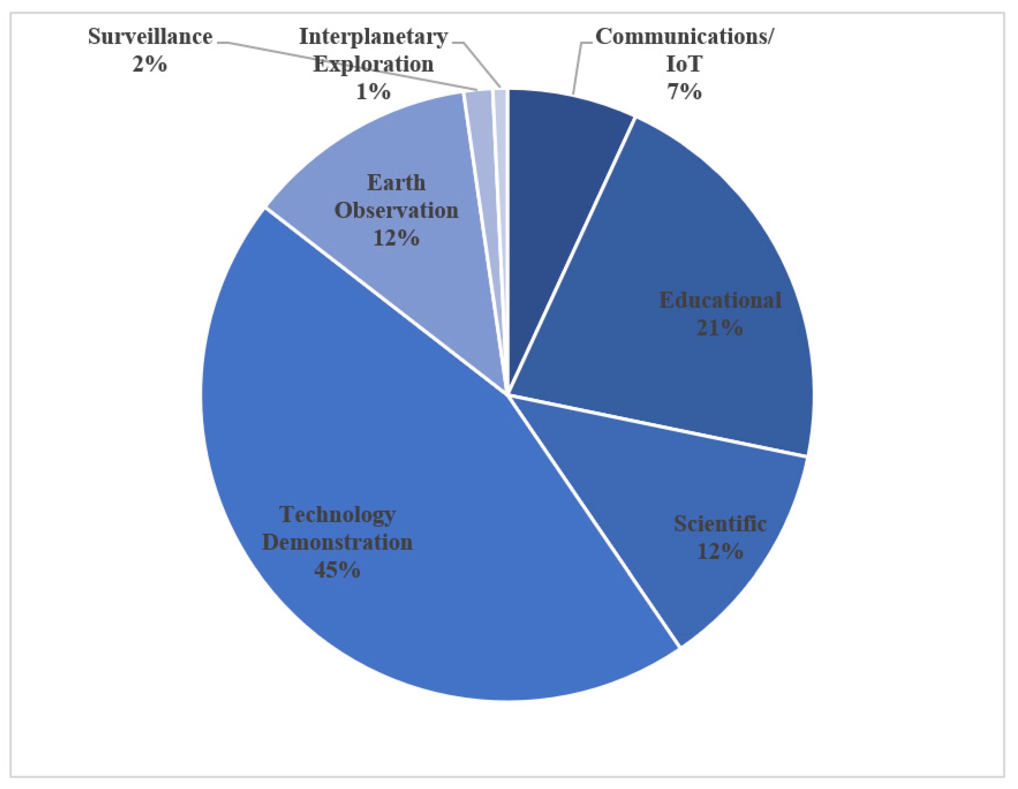
3.2. CubeSat Missions and Their Antenna Designs

Based on the specifications defined in Table 2, a type of antenna may be selected for a specific CubeSat mission according to the communications’ requirements for the mission and the limitations set by the CubeSat standards. The simplest and most used structures of CubeSat antennas are wire and patch antennas. Furthermore, planar antennas have become increasingly attractive for small satellite missions due to their low profile and compatibility with RF and microwave circuits. Microstrip patch antennas and slot antennas are two types of popular planar antenna designs for CubeSats. A literature survey based on planar antenna designs and their potential for picosatellite applications is presented in [21]. To better understand how the aforementioned restrictions are considered in current CubeSat missions, in the remaining part of this section, a comprehensive survey of the current antennas used in CubeSat missions is presented. Table 3 shows the well know frequency bands. Table 4 lists 120 CubeSat missions from 2003 to 2022 with the aim of informing the reader about the different antenna types, frequency bands, and CubeSat sizes used for different mission types. The mission selection is not exhaustive but illustrative. The choice of the missions depends on the availability of mission data related to the communication subsystem of each mission. The frequency bands used in Table 4 correspond to the IEEE standards shown in Table 3.
Figure 3 shows a breakdown of the mission types corresponding to the missions presented in Table 4. Nearly half of the missions were focused on technology demonstration, where CubeSats were used as a cost-effective way to test and validate innovative hardware or software such as novel propulsion systems, attitude control systems, or inter-satellite links, as in the case of CP6 or Cesium. The second biggest portion (21% of the missions) was devoted to educational purposes, where CubeSat were used by different academic institutions around the world to motivate students and familiarize them with satellite subsystems. It is worth mentioning that offering undergraduate students opportunities to get involved in a space-related project like CubeSats has led to a rapid increase in CubeSat launches lately. Earth observation and scientific missions each contributed 12% of all the investigated missions. In these missions, CubeSats may be used to study radiation levels in outer space, the ionosphere, and space as well as Earth weather or even monitor crops from space. Lately, CubeSat missions related to communications such as high-speed downlinks, IoT, M2M, and 5G from space have started to emerge, which corresponded to 7% of all the missions. Finally, the smallest portions of the CubeSat missions were found in surveillance with 2% and interplanetary exploration led by NASA, corresponding to 1%.
In this survey, the sizes of existing and previous CubeSats were also recorded in an effort to illustrate the overall trend in CubeSat designs. Figure 4 shows the popularity of CubeSat sizes over the 120 missions under investigation. The smallest size in the literature corresponded to 0.25U, with only one mission found. The most popular CubeSat size was found to be 1U, which is defined as the basic unit for CubeSat design. The next most popular size was 3U with 36 CubeSats in total, which showcases the potential of using 3U to accommodate more complex functions and carry more advanced technology. With the development of CubeSat missions, some larger sizes such as 6U and 12U emerged, which are associated with missions with increased power and RF budgets or payloads that require more integration real estate.
Figure 5 shows the antenna types used in the investigated CubeSat missions. We can see that monopole and dipole antennas were widely used as the primary uplink or downlink band, which normally operate at a VHF or UHF. Patch antennas operating on the S-band or L-band were the second most popular antenna type since they have a low profile, are lightweight, and usually do not require any deployment mechanism. In addition, patch antennas can provide a considerable gain improvement over monopoles and dipoles. For that reason, monopoles or dipoles and patch antennas are usually used in the same mission, where the monopole or dipole is used for low-data rate telemetry functions and the patch antennas can be used for higher data rate communications. A helical antenna is another antenna candidate that has been used in CubeSat missions. They can provide a medium directive pattern and can be easily stowed and deployed in a similar way to monopole and dipole antennas. If higher gain and high-speed downlinks are required, a higher frequency must be used (e.g., X-band, Ku-band, or Ka-band), combined with antenna arrays such as microstrip patch arrays, reflectarrays, or meshed reflectors. In more recent missions, phased arrays operating at the Ka-band have been used, where the antenna beam can be steered electronically to realize intersatellite links or accommodate varying traffic as in the case of IoT missions. Horn or guided wave antennas have also been used in CubeSat missions, operating at the Ka-band and W-band to realize high-speed downlinks and push the current CubeSat communication capabilities to their limits. Last but not least, X-band reflectarray antennas have been used in MARS CubeSat missions launched by NASA, proving that CubeSats can be used as a cost-effective way to explore different planets.
As shown in Figure 6, the most commonly used frequency band among the CubeSat missions is UHF and the combination of UHF with VHF, L-band, X-band, Ku-band, or Ka-band. Reagrdless of the mission objectives, the UHF band is mostly found in CubeSat missions, even as the primary downlink or as the backup secondary radio frequency. Moreover, S-band has also been widely used either by itself or combined with higher frequencies such as X-band or Ku-band. There are very few CubeSats that employ only the VHF, L, Ka- or W-band. This highlights the importrance of using various frequency bands in a single CubeSat mission to satisfy the variety of the mission’s requirements.
Lastly, it would be interesting to observe when each antenna type apeared in CubeSat missions through the years, starting from 2003 amd leading up to 2022. Initially, around 2003, monopole and dipole antennas were solely used in CubeSat missions due to their simplicity of design, low cost, and ease of deployment. As we move forward to 2005–2011, patch antennas made their appearance in the CubeSat community. Around 2012, meshed reflector antennas started emerging in CubeSat missions, while during 2014 and 2015, helical and reflectarray antennas were adopted. In 2017 and 2018, CubeSat missions were equiped with antenna arrays, followed by phased arrays during 2018 and 2019. Finally, during the last 3 years, horn and guided wave antennas appeared in CubeSat missions. It is important to note that once a specific antenna type appeared at a point in time, it was being used for the upcoming years as well. For example, during the last 3 years, a combination of antenna types can be found in a single CubeSat mission, which was not the case before 2011. Through the years, the complexity of CubeSat missions has increased. Therefore, the CubeSat capabilities must increase accordingly to meet the mission requirments. This is reflected in the variety of antenna types and frequency bands used by recent CubeSat missions. More advanced missions require higher data rates, higher gains, and reduced antenna sizes while keeping the satellite power budget as low as possible. As a result, from Table 5 we can draw the following conclusion: The evolution of CubeSat antennas is dictated by the requirements and complexity of the missions.

4. Single-Element CubeSat Antenna Designs

Single-element antennas vary from monopole and dipole antennas to planar, conical, and helical antennas, as well as guided wave structures like the bull’s eye antenna and metasurfaces. They are easier to construct than the antenna arrays but do not achieve such a high radiation performance compared with the antenna arrays. In 2001, monopole and dipole antennas were initially chosen and used for the communication subsystem of the CubeSat [142]. As research on CubeSats communication systems drew more scientific interest, more complex antennas were introduced. Figure 7 presents four popular antenna types after deployment on a 3U CubeSat.

4.1. Monopole and Dipole Antennas

CubeSats operating at low frequencies such as VHF or UHF are equipped with wire antennas. In most cases, a wire antenna needs to be deployed after a CubeSat is launched into space. Deployment usually involves a composite tape spring [143,144,145]. In addition, wire antennas in dual-band operation can be used to transmit and receive data at the same time, similar to the 3 λ/4 dual band monopole antenna in [146]. Instead of simply employing the monopole antenna in the form of a straight wire, the authors in [147] proposed a design for a monopole G-shaped antenna that is mounted on a CubeSat. It consists of two rectangular wire loops. The size of the antenna was smaller than the size of the CubeSat’s surface, so it could be mounted and stowed within the CubeSat body and did not need a deployment mechanism. Three structures were available based on three different frequencies of 150 MHz, 180 MHz, and 330 MHz. In [94], the authors proposed four monopoles, which were combined to form a circular polarized isotropic antenna that established communication at the initial stages of CubeSat deployment. Similar to the monopole antenna, in many instances, the length of dipole antenna is a restriction for CubeSat missions to be solved. For example, in [143], a deployable dipole antenna using a curved, bi-stable composite tape spring was outlined. The dipole antenna operated at 250 MHz, and its total length was 55.88 cm, around five times larger than a CubeSat’s edge.
In some designs, monopole and dipole antennas can also be combined and used together to achieve the goals of a mission. In 2002, one of the first CubeSats, namely “XI-IV”, was launched and presented, where a 56-cm monopole antenna was used for the uplink at 144 MHz and placed vertical to a 35-cm (tip to tip) dipole antenna used for downlink communication (telemetry and beacon) at 430 MHz. Crucial health data were broadcasted constantly via a beacon signal at 430 MHz [142]. The authors in [148] proposed a combined VHF/UHF (144/435 MHz) system. Both a dual-band dipole as well as a dual-band monopole were presented with the monopole configuration, acting as a fallback solution. An LC circuit was used as a notch filter in the UHF band to decide whether the dipole or monopole configuration was to be activated. Moreover, the authors in [149] presented a communication system consisting of an S-band transmitter along with a UHF dipole as a backup transmitter. The downlink operated at 437 MHz and the uplink at 145 MHz, and these were implemented using a VHF monopole antenna. A dual-band folded-end dipole antenna was proposed in [150] for plastic CubeSats. The folded dipole does not require any deployment mechanism as it has a low profile and wraps around the CubeSat’s body. The dipole operates at 2.5 and 4.7 GHz and is fed by a microstrip line, which is placed inside the CubeSat’s body. The proposed antenna achieved one of the highest gains that could be found on wire antennas of 7.55 and 4.9 dBi at 4.7 and 2.5 GHz, respectively. Table 6 summarizes the findings related to monopole and dipole CubeSat antennas.

4.2. Planar Antennas

One of the main objectives of wireless communications and especially satellite communications is to use multiband or wideband low-profile antennas [151]. Patch antennas are good alternatives to wire antennas, as they have a low profile, do not require a deployment mechanism, are easy to fabricate, and have relatively low costs. Patch antennas are ideal for S-band communication, which is one of the international amateur satellite frequency ranges for high bit rates. They are characterized by higher gain than the wire antennas but suffer from narrow bandwidths. An interesting use of patch antennas can be found in [152]. A standard patch antenna was used as a feed for a parabolic reflector placed inside an inflatable volume. The patch antenna had dimensions of 9 cm × 9 cm, which complied with the CubeSat standards, and its gain was 8 dBi at 2.4 GHz. By adding the parabolic reflector, the antenna gain was increased to 16 dBi at 2.4 GHz. The authors showed that a patch antenna can be used as a feed to a parabolic reflector instead of the traditional choice of a horn feed.
Another novel patch antenna design is proposed in [153], where an F-shaped patch antenna was under investigation. The results show that the patch antenna could achieve a gain of 8.5 dBi at 2.45 GHz. Furthermore, in [154] a dual-feed, L/S dual-band-stack patch antenna design is presented. This antenna operated in the L-band at 1.57 GHz for receiving the position signals from GPS satellites and in the S-band at 2.2 GHz for downlink transmission to the ground station. Even though the antenna consisted of 3 layers, it weighed less than 120 g and maintained a low profile of 11 mm, which conforms to the CubeSat standards. A Koch curve microstrip fractal antenna was presented which efficiently utilized the available space by maintaining a wide bandwidth [155]. The antenna was attached on a FR-4 substrate with dimensions of 3.5 cm × 4.5 cm and had an operating frequency range from 2.25 GHz to 2.45 GHz. The planar antennas that have been proposed for CubeSats are shown in Table 7.

4.3. Antenna Integrated with Solar Panels

Solar panels represent the main source of power for a CubeSat, and thus it is important to reserve available space for their installation on the satellite’s body. On the other hand, the antenna is another subsystem of the CubeSat that requires instalment space and is also of great importance when it comes to mission success in terms of communication. Consequently, integrating antennas with solar panels was proven to be a very efficient approach to using a CubeSat’s available space while at the same time avoiding the requirement of a deployment mechanism [161]. An integrated solar panel-antenna system must keep the received solar energy loss to low levels. Four types of integration between solar panels and antennas are presented in [162]:
  • Place patch antennas under the solar cells;
  • Create slot antennas and deposit solar cells directly on top of them [161];
  • Place transparent antennas directly on top of solar cells [161];
  • Integrate transparent antennas on solar cells [163].
Thus, solar cells with patch antennas and slot antennas where the transparency is kept high are two possible solutions for space missions.
In Table 8, examples of meshed patch antennas on a transparent borosilicate glass substrate suitable for integration with solar panels are presented as in [164]. A meshed patch antenna is similar to a microstrip patch antenna, but instead of continuous solid patch shapes, some metallic areas are removed to form a mesh. Along similar lines, the design philosophy of slot antennas takes advantage of the gaps between solar cells by creating radiating cavity-backed slots in these gaps. A slot antenna integrated with solar cells is proposed in [165], where a closed-loop meander-shaped slot antenna is wrapped around the top and bottom halves (1.5U) of a 3U CubeSat for the downlink and uplink, respectively. The way the slot antenna is wrapped around the chassis allows effective installment for solar cells. Finally, another cavity-baked slot antenna design can be found in [166]. The design can switch between left-handed circular polarization (LHCP) and right-handed circular polarization (RHCP) by changing the on and off states of the installed PIN diodes.

4.4. Conical Spiral Helix Antenna

Conical spiral and helix antennas can easily change from a 2D structure while stowed to a 3D structure during deployment. When compressing the conical spiral into a panel, it is possible to mount the antenna on one of the CubeSat’s surfaces. Once the CubeSat is launched into space, the conical spiral antenna can be easily released and flick up to its functional 3D shape. The challenges for this kind of antenna are usually related to feeding mechanisms. Designers need to avoid any impedance mismatch and provide a stable deployable mechanism. Furthermore, feeding from the top or bottom of the conical spiral shows different radiation performance. The maximum gain direction of this kind of antenna is from the smallest element to the biggest one. As shown in Table 9, in [170], a deployable helical UHF antenna is presented. The antenna can be stowed in a 10 cm × 10 cm × 5 cm package, and when deployed, it can reach up to 137.16 cm in length and 35 cm in diameter. A 5-turn helix contributes to a gain of 10 dBi, while a 2-turn taper helps to improve the axial ratio to less than 2 dB. The conductive element of the antenna is made of copper adhesive tape. Another design that employs a similar deployment concept is described in [171].

4.5. Other Antenna Designs

As shown in Table 10, the “bull’s eye” antenna, as demonstrated in [175], has grooves in the shape of a bullseye. It is useful for inter-CubeSat communications, and it is possible to be employed and used for a CubeSat swarm. In addition, it also has a low profile and high gain. Another special design presented in [176] is that of a dual-band cylindrical dielectric resonator antenna (DRA). In general, a DRA presents some interesting features, such as a small size, wide bandwidth, high radiation efficiency, and low loss, making them a good alternative for CubeSat integration. The proposed DRA utilizes a microstrip line as a feed and a rotated plus-shaped slot placed on an FR4 epoxy sheet to excite the cylindrical dielectric resonator. The resonator has a height of 5 mm and a diameter of 10 mm. The modes of operation of the resonator determine the resonant frequency of the antenna, which in this case is at 7.7 GHz and at 11.4 GHz. The simulated and measured results of this design verify the feasibility of using DRAs for CubeSat missions. The authors of [177] presented a novel S-band antenna design that provides good radiation performance and occupies a small area on a CubeSat. The antenna consists of 4 balanced inductive exciters (BIEs) placed at the top surface of a 1U CubeSat. The main idea is to transform the 1U CubeSat platform into an efficient radiator by employing characteristic mode analysis. The proposed antenna has the capability to steer the radiation beam at both principle planes as well as the capability of changing its polarization between CP and LP. Recently, metasurface antennas have been considered for deep space CubeSat missions [178]. More specifically, a metal-only modulated metasurface antenna excited by surface waves from a circular waveguide was proposed. The antenna operates at 32 GHz and achieves a gain of 24.4 dBi without needing a deployment mechanism.

4.6. Recommendation for Single-Element Antennas and CubeSat Missions

To summarize from the previous section, most of the current existing CubeSats employed single-element antennas. Dipole, monopole, and patch antennas are widely chosen as they are easy to design and deploy. The deployment mechanisms of whip antennas have been successfully implemented on many CubeSat missions. It is recommended to operate whip antennas at a lower frequency band such as UHF or VHF, as their wide signal coverage enables tracking and telemetry on these bands. However, considering the lengths of whip antennas might be too long, a CubeSat mission can deploy multiple dipole or monopole antennas to avoid complex deployment issues. Whip antennas operating on frequencies higher than S-band will have lengths several times smaller than those operating at UHF and VHF. An interesting alternative is to utilize the CubeSat body as an efficient radiator, which may provide beam steering and polarization agility benefits. More challenging applications of CubeSats where the data rates are considerably higher than 9.6 kbps require the use of higher frequency bands, such as L-, S-, Ka-, or V-band. In these cases, more sophisticated antenna structures are needed, such as the metasurface or bull’s eye antenna.
The higher potential of single-element antennas is still being explored, and many new structures other than patch and whip antennas have been developed for several CubeSat missions. However, they all aim at optimizing the antenna characteristics within the available space and weight limitations. In other words, the design of single-element antennas becomes a task of balancing the antenna performance and the limitations imposed by the CubeSat standard. Thus, flexible materials for supporting the deployment mechanism need to be investigated for specific antenna designs. A typical example is a design of membrane antennas [179] that employs a foldable membrane plated with conductors.

5. Antenna Arrays for CubeSat

There are two ways to increase the directivity and gain of an antenna. The first approach involves increasing the electrical size of the antenna, and the second approach involves combining single elements under a specific geometrical configuration. It is obvious that the first approach is more impractical for CubeSat-specific applications, as the available area is limited by the CubeSat size standards. The second approach is commonly referred to as antenna arrays and represents a strong candidate for CubeSat missions when a high gain and beam steering are required. Antenna arrays can be classified according to the spacing between the elements, the excitation phase, and the amplitude of each element, as well as the radiation pattern of each element [180]. The most common implementations of antenna arrays are the linear and two-dimensional planar arrays.
A subcategory of planar arrays is called phased arrays, which are characterized by their electronic beam scanning and the beam forming capabilities. This can be accomplished by electronically controlling the phase and amplitude at the element or subarray level. In practice, varying the phase differences and excitations of each element in an array is often achieved by phase shifters and power amplifiers. Phase shifters assign complex weights to each element, and the output signal from an array is the combination of signals from each element multiplied by their complex weights. When choosing a phase shifter, the distortion caused by group delay, inter-element interference, as well as beam squinting needs to be taken into consideration. Other effects on array performance related to phase shifters are caused by the insertion loss envelope and phase accuracy [181]. Furthermore, the operation point of the power amplifiers may influence the bit error rate (BER), considering the modulation type and the number of carriers. Therefore, the receiver array employs a low-noise amplifier, while the transmit array employs a linear power amplifier. Finally, phase array antennas offer one of the most versatile and powerful antenna candidates for CubeSat missions when beam steering or beamforming capabilities are required. Despite their attractive features, phased arrays present high power consumption, which must be taken into account in the CubeSat power budget calculations [182].
To date, most CubeSat missions have employed standard antenna designs such as wire and patch antennas (see Table 4). The dimensions and the geometry of single-element antennas impose limitations related to gain, directivity, and beam steering capability, resulting in a limited attainable data rate as well as restricted mission capabilities. For example, in IoT CubeSat missions, there are thousands of Earth terminals to which the CubeSat constellation should establish reliable links. In addition, the CubeSat swarm can form a distributed array, which can compensate for any gain variations or satellite orientation errors [183]. In such cases, antenna arrays or phased arrays are promising CubeSat antenna candidates. A collection of antenna array designs suitable for CubeSat missions is discussed in the following sections.

5.1. Linear Arrays for CubeSats

A sophisticated Yagi-Uda antenna for CubeSat attached to the eXtendable Solar Array System (XSAS) can be found in [184]. Given that the typical dipole configuration results in a gain of around 5 dBi, the authors tried to achieve a high gain with a 6-element Yagi-Uda antenna array incorporated into the deployable solar panels. The design comprises one reflector, one driven element, and four directors. Experiments showed that the length and spacing of the directors were critical for maximizing the gain of the antenna. The proposed antenna, when deployed, reaches 1.2 m in length, being attached to the 30° tilted solar panels. As shown in Table 11, at a 435-MHz operating frequency, the gain obtained was 11.5 dBi, exhibiting superior performance compared with the 5-dBi gain of a dipole configuration. Achieving a higher gain in satellite antennas would also allow for higher altitude deployment of the small satellites, relieving them from suffering high atmospheric drag.
In addition, a quad monopole antenna array was proposed with a communication system consisting of a UHF transceiver, RF splitter, and a quad four-monople antenna array. The RF splits the RF signal into a phasing network to form a single circular polarized antenna. The gain of the antenna array was 2 dBi at 436 MHz. LituanicaSAT-2 is part of the QB50 mission which in 2017 launched a 36-CubeSat swarm to explore the temporal and spatial distributions of the parameters measured in the thermosphere [185]. In [186], a W-band, 16 × 32 element, circular, polarized, phased antenna array on a single layer was presented. The antenna operated at 85 GHz with 30 dBic. The antenna also achieved beam scanning of +/−30° using a 4-bit phase shifter at the cost of rapid gain drops, especially in the range from −30° to −10°. Overall, the antenna efficiency was more than 56% for the investigated scanning range. A printed Yagi antenna with multi-frequency operation was proposed in [187]. This Yagi antenna has four printed elements and an integrated balun. Moreover, by adjusting the angle between the antenna and the CubeSat, the antenna can operate at different L- and S-band frequencies and achieve beam steering.

5.2. Planar Arrays for CubeSats

First of all, it is important to note that when incorporating an antenna array on a CubeSat, a major limiting factor will be the available surface. This factor limits the operating frequency range, as an antenna array requires a wavelength-specific spacing between its elements. Another issue with integrating antenna arrays on CubeSats is the power required for phase shifting techniques [188]. Table 12 lists the performance of planar antenna arrays. The design in [188] is an active phased planar array that complies with the CubeSat size standards. As the design was tested in the anechoic chamber, it was found that it could deliver a 5-dBi average gain at 2.5 GHz, and it might be possible to expand the design to a 16-element deployable antenna array able to produce a gain of 11 dBi on a 2U CubeSat. In [189], a reconfigurable S-band patch antenna was proposed as an improvement to the previous work performed in [190]. The antenna consists of four rectangular patches which can generate three different radiation patterns as well as three different polarisations when excited in different ways, in terms of the excitation phase.
Another design relevant to planar phased arrays on CubeSats can be found in [38]. In this design, the antenna array is aimed at inter-CubeSat communications and can enable beam scanning, as the antenna’s beam can be steered up to 40°. The array consists of several subarrays. Each subarray contains 4 patches and has a size of 30 mm × 30 mm. At a frequency of 5.8 GHz, the subarray has a gain of 5.1 dBi, while the complete array achieves a gain around 5.8 dBi. This planar phased array is placed on one of the 1U CubeSat surfaces, and all of its subarrays share the same substrate panel and are designed under the same frequency. Furthermore, another planar array design compatible with CubeSats is presented at [191]. More specifically, a 2 × 2 antenna array is proposed, utilizing annular patches as the elements which are connected with strips to a ring resonator functioning as a feeding network. The array presents circular polarization at 8.25 GHz with a gain of 13 dBi, in contrast to a single annular patch where the gain is only 7 dBi.
Moreover, in [192], a 4 × 4 planar antenna array design is proposed as a feed for parabolic reflector antennas for satellite remote sensing applications and especially the global water cycle that affects the Earth’s climate. The design has dimensions of 8.7 cm × 7.2 cm and can fit onto one of the CubeSat surfaces. The proposed array is characterized by dual frequencies at 14 GHz and 35 GHz and dual linear polarization, namely vertical and horizontal. The design utilizes the concept of aperture-coupled patch antennas. It is important to note that for lower coupling and lower undesired radiation, a thin substrate with a high dielectric constant is used for the feed network (RT/Duroid 6010). On the other hand, a thick substrate with a low dielectric constant (RO4003C) is used for the antennas, as this allows for a larger bandwidth. The design has three layers, where the 35-GHz array lies inside the empty space of a 2 × 2 14 GHz subarray. This eliminates the need for independent substrates for the different arrays. Furthermore, a 36-element RHCP patch antenna array that operates at 10.4 GHz was proposed in [193]. The array has a size of 0.9 cm × 0.9 cm and can be mounted on any 1U CubeSat surface without the need for any deployment mechanism. The array achieves a high gain of 20.1 dBi at 10.4 GHz with a low side lobe level of −14 dB while keeping the cross-polarized LHCP radiation at −18 dB.

5.3. Reflectarrays, Reflectors, and Transmitarrays for CubeSats

Deployable reflectors and reflectarrays are some of the most popular solutions for satellite missions requiring high gain in high-frequency bands. However, the option of employing deployable reflector-based antennas for CubeSat applications is still under investigation, and some novel concepts such as foldable reflectarrays, transmitarrays, and mesh deployable antennas have been proposed to solve the problems such as scaling and deployable mechanisms. As shown in Table 13, the reflectarray described in [194] consists of three flat rectangular panels that will deploy perpendicular to the side of feeding bus. They are stacked on one side of the CubeSat before flipping out, which brings design challenges when considering the thickness of the substrate. Their deployment mechanism is controlled by simple spring-loaded hinges. Reflectarrays are usually lightweight and inexpensive, but they are characterized by narrow bandwidths. A novel concept for deployable mesh reflector antennas was first proposed in [195]. The folded size of the mesh reflector can be stored in a 1.5U volume satellite body, and its functional dimension can support a 6U class CubeSat. Its physical function is similar, with an umbrella that deploys as a parabolic reflector. Compared with reflectarrays, this design can provide a higher gain and larger bandwidth but also has a larger stowage volume.
There are some designs where a reflectarray is combined with a solar array. In [101], the Integrated Solar Array and Reflectarray Antenna (ISARA) is presented as a deployable antenna operating on the Ka-band which is compatible with a 3U CubeSat and can be used for radar applications in space. Radars applications on CubeSats require a satisfactory SNR performance and have their power limited to a few watts. Thus, the antenna gain should not be lower than 35 dBi. The design consists of three 33.9 cm × 8.26 cm reflectarray panels and a microstrip feed. More specifically, square reflectarray patches are printed on a 15-mil substrate (εr = 3.00) underneath the solar panels, while the feed is composed of a 4 × 4 element microstrip patch array facing the bottom surface solar arrays at a distance of 14.67 cm. A major advantage of the ISARA against other deployable mesh reflectors or inflatable reflector antennas is that it does not occupy any payload space and is extremely lightweight. The ISARA mission was at Technological Readiness Level (TRL) 5, and it flew for 5 months to reach TRL 7.
Following the ISARA mission, the same reflectarray antenna concept was utilized in the first CubeSat mission to Mars, which was called Mars Cube One (MarCo) [196]. The CubeSats in this mission would be used as a twin communication relay for the InSight mission. More specifically, during the entry descent and landing (EDL) phase, InSight would transmit spacecraft status data at a UHF band. Each MarCo CubeSat would receive this data using a circular polarized loop antenna, and then each CubeSat would transmit at an X-band link to a 70-m Deep Space Network antenna at a distance of 160 million kilometers. The downlink antenna design was modified from the one used in the ISARA mission. First, the antenna has a small stowage volume of 0.1U, and the deployment mechanism utilizes hinges for the reflectarray and a flip-out feed. The design consists of three 19.9 cm × 33.5 cm × 1.25 cm reflectarray panels and a 4 × 2 element microstrip patch feed. The reflectarray panels are designed on a Rogers RO4003 woven glass-reinforced hydrocarbon ceramic material with a thickness of 0.812 mm and a constant of εr = 3.55, while the spacing of the elements is 1.168 cm and 1.189 cm in the x and y directions, respectively. The spacing of the patches and the thickness of the substrate were chosen to provide a sufficient bandwidth [197]. The MarCO 6U CubeSats demonstrated the suitability of CubeSats for deep space missions and also the importance of high-gain antennas and folded panel reflectarrays for high-data rate communications.
Another reflectarray design suitable for a 6U CubeSat can be found on [196]. The design consists of 15 reflectarray deployable panels forming an array of 255 × 212 elements that are 81.8 cm × 98.4 cm in size, a feed horn, 3 telescoping waveguides, a rectangular hyperboloid subreflector, a rectangular-to-circular waveguide, and 3 struts to align the subreflector with respect to the feed. The simulated gain was found to be 48 dBi at 35.75 GHZ with an aperture efficiency of 44%. Along similar lines, a Large-Area Deployable Reflectarray (LADeR) concept was proposed by the authors of [198]. In this design, the array elements are etched on a polyimide sheet which is supported by a flexible substrate made of a quartz-epoxy composite. The reflectarray, when stowed, occupies 4U, and when deployed, it has a surface area of 1.5 m × 1.5 m, which provides a high X-band gain of 39.6 dBi. The proposed LADeR concept can be used in future deep space missions or to establish high-speed downlinks. A similar concept to reflectarrays is transmitarray antennas, where the transmission characteristics of the impinging wave are studied. A circular polarized transmitarray was proposed for CubeSat inter-satellite links in [199]. The transmitarray is fed by an offset, 3-D printed, corrugated CP horn, which would be placed and deployed from the side of the 3U CubeSat. A transmitarray utilizes the variable rotation technique to provide the desired phase shift and collimate the beam toward the direction φ , θ = 0 ° , 20 ° . The array achieves an LHCP gain of 31.6 dBi at 24.6 GHz and a 1-dB gain bandwidth of 5.7%.
Table 13. Performance of reflectors, reflectarrays, and transmitarrays.
Type of AntennaFrequency
(GHz)
Gain
(dBi)
−10 dB
BW
(MHz)
Deployable
Reflectarray
[194]
26G
8.425
33.5
>28
>100
>100
Yes
Yes
Mesh Reflector
[195,200]
35.7542.6N/AYes
Integrated Solar Array and Reflectarray
[101]
3633.5>100Yes
MarCO
[196]
8.42529.250Yes
Cassegrain Reflectarray
[196]
35.7548N/AYes
LADeR Reflectarray
[198]
8.439.6N/AYes
Transmitarray
[199]
24.631.6N/AYes

5.4. Log-Periodic Crossed-Dipole Arrays

Dipoles and wire antennas have been two of the most popular designs used in CubeSats. A disadvantage of employing dipole antennas is the fact that they do not exhibit circular polarization unless crossed together, which makes the antenna more flexible in terms of capturing electromagnetic waves and also more insensitive to signal degradation due to harsh weather conditions. Thus, in [201], a log-periodic crossed-dipole array was proposed. This design could be a major candidate for CubeSat space communications due to its directive radiation pattern, high gain, and wide bandwidth. The antenna is fabricated using a curved composite bi-stable tape spring, which will allow for a very compact and small stowed volume as well as a simple deployment roll-unroll mechanism. Moreover, each dipole element should be crossed with one another while the differences between the dipole pair lengths are calculated on a log-periodic scale. Finally, the multiband operation of the antenna elements results in an antenna array with wideband operation.

5.5. Slotted Waveguide Antenna Arrays

An antenna design that can be used as a synthetic-aperture radar (SAR) for remote sensing applications can be found in [202]. More specifically, a low profile, high efficiency, and high-power capacity parallel plate slotted waveguide antenna array design is proposed. First of all, the radiating slots are located on the wall of a waveguide. The antenna system consists of two layers. The first layer is an RF feeder panel, and the second is an aluminium parallel plate with a slotted array. There are six square antenna panels that can be folded into three adjacent CubeSat surfaces and be deployed as a large rectangular panel. Each single panel weighs around 1 kg, has dimensions of 0.7 m × 0.7 m, and has multiple coupling slots that are not parallel to each other. The antenna array when deployed is 4.9 m in length, and it can achieve a gain of 34.9 dBic at 9.56 GHz. To summarize, the proposed design is suitable for small satellite applications, but improvements can be made for reducing the system loss and weight due to its complex structure.

5.6. Inflatable Antenna Arrays

Inflatable antennas can realize CubeSat interplanetary missions as they can increase the achievable data rate as well as the antenna gain [152]. The use of inflatable antennas as cooperative communication techniques to form antenna arrays is investigated in [203]. Such arrays could be used to relay information from different places in the solar system, enabling CubeSat missions in geostationary orbit (GEO). The technique of forming a beam from several inflatable antennas installed on different CubeSats is investigated. The gain of the array with n inflatable antennas is increased by a factor of n2 minus the losses of the system. The gain of the array is also increased by increasing the diameter of the individual inflatable antennas constituting the array. On the other hand, when employing the beam forming technique, atomic clocks on each CubeSat may be required to synchronize the transmission and the inter-satellite communication.

5.7. Retrodirective or Self-Steering Antenna Arrays

CubeSat is an emerging and rapid-growing technology that might replace conventional big satellites. Several CubeSat missions involve the deployment of CubeSat swarms which can overcome the capabilities and functionalities of larger satellites. To accomplish this, an efficient crosslink is required for inter-CubeSat communication. An interesting solution to this can be given by employing retrodirective arrays (RDAs) which make the CubeSat network dynamically reconfigurable [204]. An RDA can be considered an alternative beam-steering antenna design for nanosatellite applications. The potential of a self-steering antenna array application for distributed CubeSat networks is investigated in [205]. A self-steering antenna, also named a retrodirective antenna, can sense and record the direction of the incoming signal and then send an outgoing signal along that same direction. An RDA has the advantage of not requiring prior knowledge of the position of the intended receiver, and the steering is also performed at the hardware level, which eliminates the need for complex digital signal processing. The main challenge that comes with the integration of RDA into CubeSat is the power limitation imposed by the nanosatellite platform. In [204], the design is divided into three modules: the detection of arrival (DOA), the communication array, and the tracking and steering control. First of all, the antenna array consists of 4 patch elements spaced at half-wavelength distances and fabricated on Rogers RT/Duroid 6002 substrate operating at 9.67 GHz for receiving mode and at 9.59 GHz for transmitting mode. The DOA array utilizes the null scanning technique for power detection, and this information is used by the control module to retrodirect a signal back to the interrogator. The overall design is composed by two four-layer PCBs: one for communication purposes and one for power detection. Finally, the 4-element 1-D RDA was designed to fit a 1.5U CubeSat and consumes 1 W of power, which complies to the CubeSat standards.
Moreover, in [206], another RDA design was proposed that eliminates phase shifters. This design consists of a cross-shaped patch array with a total of eight elements printed on a Rogers TMM3 substrate and a quadruple subharmonic mixer utilizing anti-parallel diodes as a mixer. The reason why quadruple subharmonic mixing is used is to achieve phase conjugation. Phase conjugation is a technique used to achieve retrodirectivity without any use of phase shifters, appearing on phased antenna arrays, as well as to relax the requirement of a high-frequency local oscillator (LO). The retrodirective array operates at 10.5 GHz, and the array spacing is at 1.38 cm, demonstrating circular polarization and two-dimensional steering [207].

5.8. Interferometer (Large Antenna Arrays)

The research about antenna array technology in the Deep Space Network (DSN) has been being undertaken by NASA since the 1960s [208]. The antenna array for deep space consists of elements located in different positions far away from each other forming a very large antenna aperture. Generally, a large antenna array plays the role of the receiver that receives the signals from a deep space source. By combining the signals received by each element according to their coherence and incoherence among the noise signal, a high SNR can be achieved. As a result, by improving the SNR of the receiver, the deep space network could support an increased data load with higher efficiency.
Compared with an antenna array installed in a single CubeSat, as mentioned in previous sections, this large antenna array is formed by combining many CubeSats located in different locations. This may introduce synchronization problems, as each CubeSat runs on a different clock. Therefore, when performing signal synthesis, it is necessary to solve the problems of phase correlation, time synchronization, and delay compensation. An example of a CubeSat swarm network was realized in the QB50 project, a collaboration among 50 different multi-national partners. The resulting cooperative QB50 CubeSat network is envisaged to have a higher degree of functionalities than conventional satellites. Another example of an interferometer antenna array is the Very Large Array (VLA) located in New Mexico in the United States [209]. It consists of 27 steerable antennas forming a 3-arm array in the shape of the letter “Y”. The largest distance between antenna elements to the center of the “Y” is up to 21 km. A various range of operating bandwidths is available in this large receiving system from 50 MHz to 97 kHz.

5.9. Arraying Techniques and Correlation Algorithms

There are five basic arraying techniques, namely full-spectrum combining (FSC), complex-symbol combining (CSC), symbol-stream combining (SSC), baseband combining (BC), and carrier arraying (CA). Among these techniques, FSC can achieve an optimized remote sensing performance [210]. It can be used in the case of a weak carrier signal that is hard to track with a single antenna. The gross signal delay and phase offset between antennas are adjusted before signal combination from geometry calculations. The residual relative delay and phase can be estimated from the signal cross-correlation of each individual antenna.
There are several correlation algorithms that can be employed in antenna arrays. The Eigen algorithm can maximize the SNR from complex weights, but the computational complexity is proportional to the number of antennas squared [211]. Furthermore, there is the SUMPLE algorithm that can be applied to weak signals through the cross-correlation of each antenna element. The number of iterations of SUMPLE is proportional to the number of antennas [212]. To decrease the combining loss introduced in SUMPLE, a matrix-free (MF) algorithm can be used [213]. Based on the SUMPLE and MF algorithms, a new method named the variable step size matrix-free power (SVS-MF) method was proposed by the National Laboratory of Science and Technology on Antennas and Microwaves at Xidian University [214]. Aside from using the cross-correlation of each antenna, this method computes the variance of weights and updates data for each iteration, thus achieving a low combining loss for very weak signals with a high convergence rate. To conclude, a high-performance correlation algorithm is equally significant to the geometry and aperture of the antenna array for a successful deep space CubeSat swarm. Based on the existing algorithms, improvements could be made in terms of reducing the computational complexity and further improving the SNR at the receiver.

5.10. Recommendations for Antenna Arrays

As CubeSat applications are becoming more popular, CubeSat mission communication requirements are becoming more demanding. Researchers and developers around the world design CubeSats with increased capabilities in terms of achievable data rate, gain, and bandwidth. To meet such requirements, the migration from single-element antennas to antenna arrays for CubeSats is imminent. Antenna arrays are an effective way to increase the gain of single-element antennas by combining single antennas under a specific geometrical configuration. The integration of antenna arrays on the CubeSat platform can be approached using two different methods. In the first method, an antenna array along with a corresponding deployment mechanism is installed on a single CubeSat, while in the second method, many CubeSats, namely a swarm, are required to form the overall antenna array, where each satellite has a single-element antenna installed on it.
To date, most CubeSat missions employ single-element antennas for their communication. Missions that utilize antenna arrays are few, as the integration of antenna arrays on the CubeSat platform is still under research. The reason for this is that antenna arrays might require a complex deployment mechanism as in the case of linear arrays. Furthermore, antenna arrays may require phase shifters for beam steerability, which in turn demands board processing capabilities and an increased power budget. The choice of arraying techniques and correlation algorithms plays a vital role in the effective function of an antenna array. Lastly, when using CubeSat swarms to form an antenna array, clock synchronization between the different CubeSats is of high importance.
Despite the current difficulties of combining CubeSats with antenna arrays, there are many advantages that encourage their use for CubeSat missions. First, CubeSats equipped with a high-gain slotted waveguide antenna array might be used for radar and remote sensing applications such as SAR. Moreover, from the recent NASA mission called MarCo, it can be observed that CubeSats with reflectarrays could be used for deep space applications to relay data between the Earth and the main mission spacecraft. In addition, inflatable antennas installed on several CubeSats in different locations can form an array of inflatable antennas with beam forming capabilities, realizing geostationary Earth orbit or even interplanetary CubeSat missions. Finally, by using retrodirective antenna arrays, effective intersatellite links (ISLs) can be established inside a CubeSat swarm. A swarm equipped with RDAs can even outrun the capabilities of conventional big satellites. The current research on different types of antenna arrays for CubeSats for applications that exceed their current capabilities is of considerable importance. The typical operating frequency of antenna arrays is higher than that of single-element antennas spanning from S-band to W-band. Most of the research is focused on the X- or Ka-band frequency bands by using active phased planar arrays or reflectarrays.

6. Comparison of Single-Element Antennas with Antenna Arrays

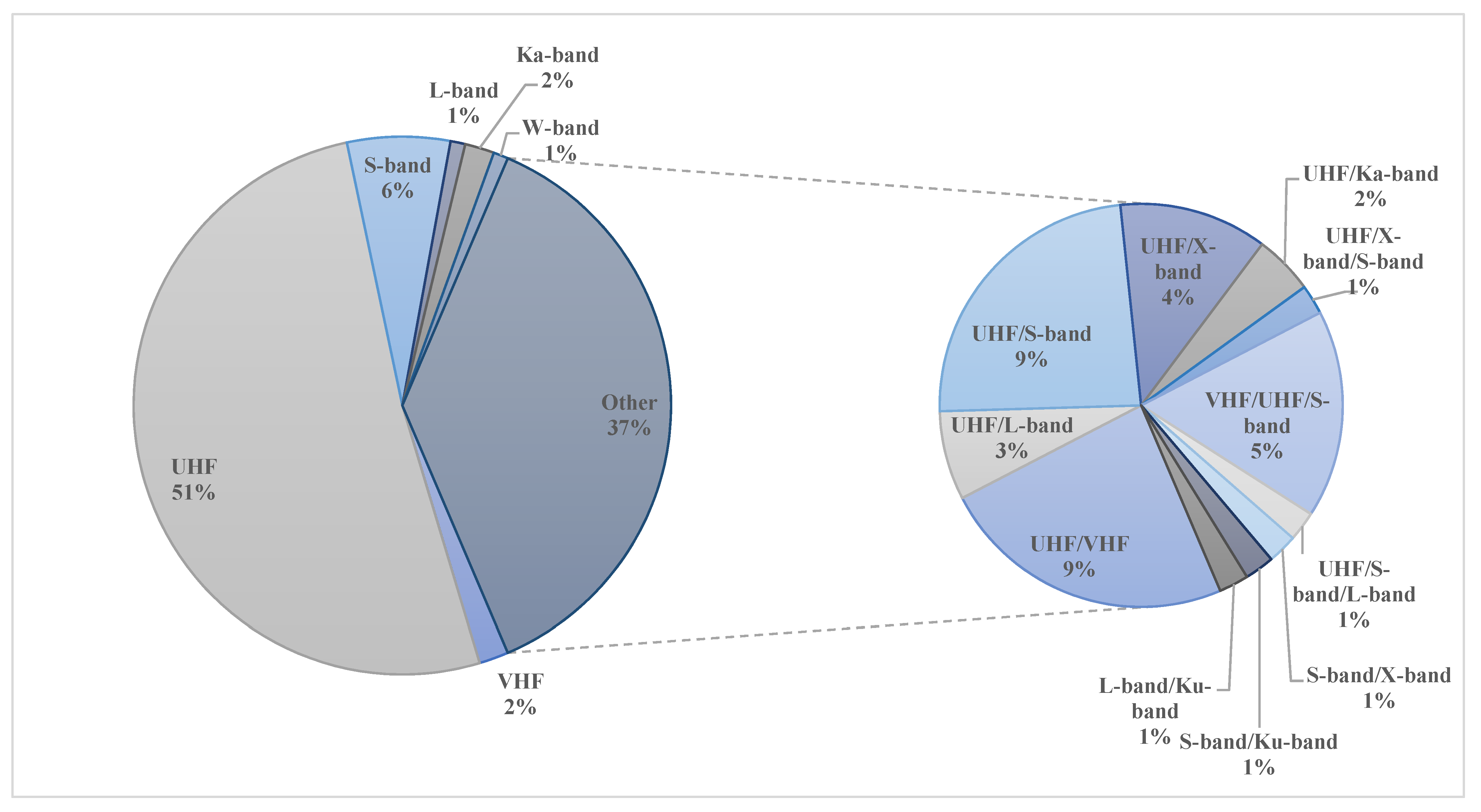
6.1. Operating Frequency Bands

When examining the aforementioned antenna designs, we conclude that most of the single-element antennas including whip antennas, patch antennas, helix antennas, and other special antennas are operating on UHF, VHF, or S-band. More specifically, monopole and dipole antennas are more likely to be designed on the UHF and VHF bands, while patch antennas and microstrip antennas usually operate on S-band. Very few antennas such as the bull’s eye antenna might aim for a much larger frequency of up to 60 GHz. On the other hand, for the antenna arrays, a large diversity in operating frequencies can be observed. As presented in Figure 8, although a number of antenna arrays operate on UHF or VHF, most of the investigated designs operate on much higher frequency bands such as X-band, C-band, or Ka-band. As far as the bandwidth is concerned, single-element antennas and antenna arrays can offer a bandwidth within range from 400 kHz to 1.5 GHz and from 50 MHz to 1.7 GHz, respectively, even though there are some antenna designs that turned out to be extremely wideband, with bandwidths as high as 10 GHz. Nonetheless, there is no unique characterization of bandwidths that can be applied to different antennas, as the antenna specifications are highly associated with the operating frequency.

6.2. Gain

Single-element antennas and antenna array designs for CubeSats show different gain characteristics. The use of single-element antennas on a space-restricted platform like the CubeSat greatly limits the mission’s high gain potential. Designs such as monopole, dipole, and planar antennas present a gain between 2–9 dBi. Furthermore, when a deployment mechanism is included in the antenna design, the gain of single-element antennas can be increased. Example designs include conical spiral, helical, and inflatable antennas. In such designs, the antenna size, when deployed, can be much larger than the CubeSat itself, and thus the gain can reach a value of 16 dBi. In addition, the gain can be increased by using antenna arrays. For instance, in the case of reflectarrays, the gain can reach up to 48 dBi, which enables long-distance deep space CubeSat missions. A comparison between the achievable gain of single-element antennas and antenna arrays is illustrated in Figure 9. As expected, the antenna arrays offer higher gain compared with single-element antennas by efficiently combining the radiation patterns of different elements in a desired direction.

7. Conclusions

7.1. Lessons Learned

The mission requirement is the one of the most crucial parameters that a CubeSat designer must consider when deciding upon the type of antenna. Single-element antennas such as monopoles or dipoles can be found in all types of missions as either as the primary or secondary low data rate radios. On the other hand, the gain superiority and beam steering capabilities of arrays renders them suitable for deep space exploration, Earth observation, and communication or IoT missions. That aside, their beam steering ability and flexible radiation patterns make them suitable candidates for CubeSat swarms. In the flowchart in Figure 10, a guide on antenna selection for different CubeSat missions is presented. The antenna designer first chooses the type of mission under development, and then several recommended frequency bands are proposed. The next condition relates to the gain requirements, namely low or high gain, and the operating frequency. Following the gain condition, and considering the cost of the antenna, the designer is given a pool of different antennas from which the desired antenna type can be easily selected. Finally, after selecting a specific antenna type, the designer can refer to the related section of the text in which the selected antenna type is being discussed and analyzed more thoroughly.

7.2. Concluding Remarks

This paper investigated different antenna designs for CubeSat, which are categorized as single-element antennas and antenna arrays. The background on CubeSats and their subsystems was presented to provide newcomers with the fundamental knowledge on CubeSat technologies. Furthermore, the specifications and restrictions posed by the CubeSat platform were analyzed. Following that, 120 CubeSat missions dating from 2003 to 2022 were reviewed, and their antenna specifications and characteristics were extracted and tabulated. In addition, a survey on single-element antennas and antenna array designs was conducted with the aim of capturing the current as well as future CubeSat trends from an antenna point of view.
Single-element antennas can be classified as whip antennas (monopole or dipole), patch antennas, antennas integrated with solar panels, inflatable antennas, conical spiral antennas, helical antennas, and some specially designed antennas. Whip antennas are good candidates for downlink antennas as they are relatively easy and cheap to construct. Monopole and dipole antennas along with a deployment mechanism are popular among current educational and scientific CubeSat missions. On the other hand, planar antennas present a number of advantages against their monopole and dipole counterparts. First of all, they have low profiles, higher gain, and eliminate the need for a deployment mechanism. Planar antennas can be placed on any of the CubeSat’s surfaces and operate mostly on S-band. Moreover, the printed antennas on the solar panels have similar characteristics to patch antennas, but their advantage is that they do not occupy any payload or chassis space. Planar antennas are currently being used in test and demonstration CubeSat missions, which makes them very likely to replace their monopole and dipole counterparts soon. Inflatable, helical, and conical spiral antennas are currently under research, where only the helical antenna was found to be used in a CubeSat mission. Such antenna designs require a deployment mechanism, but they present superior gain characteristics to the whip or the planar antennas, so they are recommended for technology demonstration missions. As far as the antenna arrays are concerned, current research is more focused on reflectarrays, transmitarrays, and planar arrays, as well as different arraying techniques and correlation algorithms. Antenna arrays are more suitable for deep space, communications or the IoT, and Earth observation missions.
From the 120 investigated CubeSat missions, it can be concluded that the interest of the space community lies in new technology demonstration, where the CubeSat serves as a cost-effective way of launching and evaluating experiments and technologies in space. Aside from that, a big portion of CubeSat missions is devoted to educational purposes. This plays an important role in the advent of CubeSat technology in recent years, as CubeSats are now widely designed and built by academic institutions and start-up companies. Exploring the universe and learning more about the composition of the weather in space and on Earth is also another potential use of CubeSats. Finally, the most recent missions have been focused on high-speed communications, the IoT, and 5G from space. These missions will be the main driver for the future development of CubeSat technology for the years to come. It is important to note that most of the IoT and 5G from space missions are based on CubeSat constellations or swarms. In such cases, the tiny form of a CubeSat is not a disadvantage but rather an advantage for scalability. The coordinated function of each CubeSat in the swarm will result in unprecedented capabilities by redefining space missions. All these technological advances would be impossible without tiny, but at the same time mighty, CubeSats.

Author Contributions

Writing—original draft preparation, S.L., P.I.T. and A.T.; methodology, S.L., P.I.T., R.R., F.T. and S.A.; formal analysis, S.L., P.I.T., R.R., F.T. and S.A.; investigation, L.M. and F.T.; resources, S.L., P.I.T. and A.T.; data curation, S.L.; writing—original draft preparation, S.L., P.I.T., R.R. and A.T.; writing—review and editing, L.M., M.U.A.K., S.I., F.T. and S.A.; visualization, P.I.T.; supervision, R.R., F.T. and L.M.; project administration, S.L. All authors have read and agreed to the published version of the manuscript.

Funding

This research received no external funding.

Conflicts of Interest

The authors declare no conflict of interest.

References

  1. Shimmin, R.; Agasid, E.; Burton, R.; Carlino, R.; Defouw, G.; Perez, A.; Karacaliglu, A.; Klamm, B.; Rademacher, A.; Schalkwyck, J. Small Spacecraft Technology State of the Art; NASA Mission Design Division Ames Research Center, Moffett Field: Santa Clara, CA, USA, 2015; Volume NASA/TP–2015–216648/REV. [Google Scholar]
  2. Xue, Y.; Li, Y.; Guang, J.; Zhang, X.; Guo, J. Small satellite remote sensing and applications—History, current and future. Int. J. Remote Sens. 2008, 29, 4339–4372. [Google Scholar] [CrossRef]
  3. Puig-Suari, J.; Turner, C.; Ahlgren, W. Development of the standard CubeSat deployer and a CubeSat class PicoSatellite. In Proceedings of the 2001 IEEE Aerospace Conference Proceedings (Cat. No.01TH8542), Big Sky, MT, USA, 10–17 March 2001; Volume 1, pp. 347–353. [Google Scholar]
  4. Wuerl, A.; Wuerl, M. Lessons learned for deploying a microsatellite from the International Space Station. In Proceedings of the 2015 IEEE Aerospace Conference, Big Sky, MT, USA, 7–14 March 2015; pp. 1–12. [Google Scholar]
  5. Twiggs, B.; Puig-Suari, J. CUBESAT Design Specifications Document; Stanford University: Stanford, CA, USA; California Polytechnical Institute: San Luis Obispo, CA, USA, 2003. [Google Scholar]
  6. ESA. First P-Pod Integration. Available online: http://www.esa.int/spaceinimages/Images/2012/02/First_P-POD_integration2 (accessed on 30 December 2021).
  7. Swartwout, M. The first one hundred CubeSats: A statistical look. J. Small Satell. 2013, 2, 213–233. [Google Scholar]
  8. Klofas, B.; Anderson, J.; Leveque, K. A Survey of Cubesat Communication Systems. In Proceedings of the 5th Annual CubeSat Developers Workshop, San Luis Obispo, CA, USA, 9–11 April 2008. [Google Scholar]
  9. Chahat, N.; Decrossas, E.; Gonzalez-Ovejero, D.; Yurduseven, O.; Radway, M.J.; Hodges, R.E.; Estabrook, P.; Baker, J.D.; Bell, D.J.; Cwik, T.A.; et al. Advanced cubesat antennas for deep space and earth science missions: A review. IEEE Antennas Propag. Mag. 2019, 61, 37–46. [Google Scholar] [CrossRef] [Green Version]
  10. Malphrus, B.K.; Freeman, A.; Staehle, R.; Klesh, A.T.; Walker, R. 4—Interplanetary CubeSat missions. In Cubesat Handbook; Cappelletti, C., Battistini, S., Malphrus, B.K., Eds.; Academic Press: Cambridge, MA, USA, 2021; pp. 85–121. [Google Scholar]
  11. Tummala, A.R.; Dutta, A. An overview of cube-satellite propulsion technologies and trends. Aerospace 2017, 4, 58. [Google Scholar] [CrossRef] [Green Version]
  12. Santoni, F.; Piergentili, F.; Donati, S.; Perelli, M.; Negri, A.; Marino, M. An innovative deployable solar panel system for Cubesats. Acta Astronaut. 2014, 95, 210–217. [Google Scholar] [CrossRef]
  13. Bunce, D.T.; Bassett, K.P.; Ghosh, A.R.; Barnett, P.R.; Haken, D.M.; Coverstone, V.L.; Yost, B.D.; Feller, J.R.; Agasid, E.F. Microvascular Composite Radiators for Small Spacecraft Thermal Management Systems. In Proceedings of the 30th Annual AIAA/USU Conference on Small Satellites, Logan, UT, USA, 6–11 August 2016. [Google Scholar]
  14. Gao, S.; Brenchley, M.; Unwin, M.; Underwood, C.I.; Clark, K.; Maynard, K.; Boland, L.; Sweeting, M.N. Antennas for small satellites. In Proceedings of the 2008 Loughborough Antennas and Propagation Conference, Loughborough, UK, 17–18 March 2008; pp. 66–69. [Google Scholar]
  15. Selva, D. A survey and assessment of the capabilities of Cubesats for Earth observation. Acta Astronaut. 2012, 74, 50–68. [Google Scholar] [CrossRef]
  16. Schaffner, J. The Electronic System Design, Analysis, Integration, and Construction of the Cal Poly State University CP1 CubeSat. In Proceedings of the 16th Annual AIAA/USU Conference on Small Satellites, Logan, UT, USA, 12–15 August 2002. [Google Scholar]
  17. Theoharis, P.I.; Raad, R.; Tubbal, F.; Khan, M.U.A.; Liu, S. Software-Defined Radios for CubeSat Applications: A Brief Review and Methodology. IEEE J. Miniat. Air Space Syst. 2020, 2, 10–16. [Google Scholar] [CrossRef]
  18. Olivieri, S.J.; Aarestad, J.; Pollard, L.H.; Wyglinski, A.M.; Kief, C.; Erwin, R.S. Modular FPGA-based software defined radio for CubeSats. In Proceedings of the 2012 IEEE International Conference on Communications (ICC), Ottawa, ON, Canada, 10–15 June 2012; pp. 3229–3233. [Google Scholar]
  19. Bouwmeester, J.; Guo, J. Survey of worldwide pico-and nanosatellite missions, distributions and subsystem technology. Acta Astronaut. 2010, 67, 854–862. [Google Scholar] [CrossRef]
  20. Abulgasem, S.; Tubbal, F.; Raad, R.; Theoharis, P.I.; Lu, S.; Iranmanesh, S. Antenna Designs for CubeSats: A Review. IEEE Access 2021, 9, 45289–45324. [Google Scholar] [CrossRef]
  21. Tubbal, F.E.; Raad, R.; Chin, K.W. A Survey and Study of Planar Antennas for Pico-Satellites. IEEE Access 2015, 3, 2590–2612. [Google Scholar] [CrossRef] [Green Version]
  22. Rowland, D.E.; Hill, J.; Uribe, P.; Klenzing, J.; Hunsaker, F.; Fowle, M.; Simms, K.; Hancock, H.; Saulino, M.; Guzman, D.; et al. The NSF Firefly CubeSat mission: Rideshare mission to study energetic electrons produced by lightning. In Proceedings of the 2011 Aerospace Conference, Big Sky, MT, USA, 5–12 March 2011; pp. 1–12. [Google Scholar]
  23. Qiao, L.; Rizos, C.; Dempster, A.G. Analysis and comparison of CubeSat lifetime. In Proceedings of the 12th Australian Space Development Conference, Adelaide, Australia, 8–10 July 2013. [Google Scholar]
  24. Sweeting, M.N.; Underwood, C.I. Small Satellite Engineering and Applications. In Spacecraft Systems Engineering; John Wiley & Sons, Ltd.: Hoboken, NJ, USA, 2011; pp. 575–605. [Google Scholar]
  25. Wilson, J.; Cucinotta, F.; Golightly, M.; Nealy, J.; Qualls, G.; Badavi, F.; De Angelis, G.; Anderson, B.; Clowdsley, M.; Luetke, N.; et al. International space station: A testbed for experimental and computational dosimetry. Adv. Space Res. 2005, 37, 1656–1663. [Google Scholar] [CrossRef]
  26. Navarathinam, N.; Lee, R.; Chesser, H. Characterization of Lithium-Polymer batteries for CubeSat applications. Acta Astronaut. 2011, 68, 1752–1760. [Google Scholar] [CrossRef]
  27. Waydo, S. CubeSat design for LEO-based Earth science missions. In Proceedings of the IEEE Aerospace Conference, Big Sky, MT, USA, 9–16 March 2002; pp. 435–445. [Google Scholar]
  28. Wells, J.; Stras, L.; Jeans, T. Canada’s Smallest Satellite: The Canadian Advanced Nanospace Experiment (CanX-1). In Proceedings of the 16th Annual AIAA/USU Conference on Small Satellite, Logan, UT, USA, 12–15 August 2002. [Google Scholar]
  29. Schmidt, M.; Zeiger, F.; Schilling, K. Design and implementation of in-orbit experiments on the pico-satellite UWE-1. In Proceedings of the 57th International Astronautical Congress, IAC-06-E2, Valencia, Spain, 2–6 October 2006; Volume 1. [Google Scholar]
  30. Long, M.; Lorenz, A.; Rodgers, G.; Tapio, E.; Tran, G.; Jackson, K.; Twiggs, R.; Bleier, T.; Solutions, S. A cubesat derived design for a unique academic research mission in earthquake signature detection. In Proceedings of the 16th Annual AIAA/USU Conference on Small Satellite, Logan, UT, USA, 12–15 August 2002. [Google Scholar]
  31. Antunes, S. DIY Satellite Platforms: Building a Space-Ready General Base Picosatellite for Any Mission; O’Reilly Media, Inc.: Sebastopol, CA, USA, 2012. [Google Scholar]
  32. Lemmer, K. Propulsion for CubeSats. Acta Astronaut. 2017, 134, 231–243. [Google Scholar] [CrossRef]
  33. Mueller, J.; Hofer, R.; Ziemer, J. Survey of Propulsion Technologies Applicable to Cubesats; Jet Propulsion Laboratory, National Aeronautics and Space Administration: Pasadena, CA, USA, 2010. [Google Scholar]
  34. Falbel, G.; Puig-Suari, J.; Peczalski, A. Sun oriented and powered, 3 axis and spin stabilized CubeSats. In Proceedings of the IEEE Aerospace Conference, Big Sky, MT, USA, 9–16 March 2002; Volume 1, pp. 447–455. [Google Scholar]
  35. Cockrell, J.; Alena, R.; Mayer, D.; Sanchez, H.; Luzod, T.; Yost, B.; Klumpar, D. EDSN: A Large Swarm of Advanced Yet Very Affordable, COTS-Based Nanosats that Enable Multipoint Physics and Open Source Apps. In Proceedings of the 26th Annual AIAA/USU Conference on Small Satellite, Logan, UT, USA, 13–16 August 2012. [Google Scholar]
  36. Budianu, A.; Castro, T.J.W.; Meijerink, A.; Bentum, M.J. Inter-satellite links for cubesats. In Proceedings of the 2013 IEEE Aerospace Conference, Big Sky, MT, USA, 2–9 March 2013; pp. 1–10. [Google Scholar]
  37. Radhakrishnan, R.; Edmonson, W.W.; Afghah, F.; Rodriguez-Osorio, R.M.; Pinto, F.; Burleigh, S.C. Survey of Inter-Satellite Communication for Small Satellite Systems: Physical Layer to Network Layer View. IEEE Commun. Surv. Tutor. 2016, 18, 2442–2473. [Google Scholar] [CrossRef] [Green Version]
  38. Martínez, R.-O.R.; Fueyo, R.E. A Hands-On Education Project: Antenna Design for Inter-CubeSat Communications [Education Column]. IEEE Antennas Propag. Mag. 2012, 54, 211–224. [Google Scholar]
  39. Taylor, J. Deep Space Communications; John Wiley & Sons, Inc.: Hoboken, NJ, USA, 2016; The Deep Space Network; pp. 15–35. [Google Scholar] [CrossRef]
  40. Palo, S.E. High rate communications systems for CubeSats. In Proceedings of the 2015 IEEE MTT-S International Microwave Symposium, Phoenix, AZ, USA, 17–22 May 2015; pp. 1–4. [Google Scholar]
  41. Popescu, O. Power Budgets for CubeSat Radios to Support Ground Communications and Inter-Satellite Links. IEEE Access 2017, 5, 12618–12625. [Google Scholar] [CrossRef]
  42. Park, Y.-K.; Kim, G.-N.; Park, S.-Y. Novel Structure and Thermal Design and Analysis for CubeSats in Formation Flying. Aerospace 2021, 8, 150. [Google Scholar] [CrossRef]
  43. National Academies of Sciences and Medicine. Handbook of Frequency Allocations and Spectrum Protection for Scientific Uses; National Academies Press: Washington, DC, USA, 2015. [Google Scholar]
  44. Funase, R.; Takei, E.; Nakamura, Y.; Nagai, M.; Enokuchi, A.; Yuliang, C.; Nakada, K.; Nojiri, Y.; Sasaki, F.; Funane, T.; et al. Technology demonstration on University of Tokyo’s pico-satellite “XI-V” and its effective operation result using ground station network. Acta Astronaut. 2007, 61, 707–711. [Google Scholar] [CrossRef]
  45. Doering, T.J. Development of a Reusable Cubesat Satellite Bus Architecture for the KYSAT-1 Spacecraft. Master’s Thesis, University of Kentucky, Lexington, KY, USA, 2009. [Google Scholar]
  46. Kayal, H.; Baumann, F.; Briess, K.; Montenegro, S. BEESAT: A pico satellite for the on orbit verification of micro wheels. In Proceedings of the Recent Advances in Space Technologies, Istanbul, Turkey, 14–16 June 2007; pp. 497–502. [Google Scholar]
  47. Konda, Y.; Usuda, T.; Sagami, T.; Omagari, K.; Kashiwa, M.; Matunaga, S. Development of attitude determination and control system for pico-satellite cute-1.7+ APD. In Proceedings of the 16th Workshop on JAXA Astrodynamics and Flight Mechanics, Sagamihara, Japan, 1–2 August 2006; pp. 242–247. [Google Scholar]
  48. Eide, E.; Ilstad, J. NCUBE-1, the first Norwegian CUBESAT student satellite. In Proceedings of the 16th ESA Symposium on European Rocket and Balloon Programmes and Related Research, St. Gallen, Switzerland, 2–5 June 2003; pp. 85–88. [Google Scholar]
  49. Maeno, M.; Omagari, K.; Iljic, T.; Masumoto, S.; Fujiwara, K.; Konda, Y.; Yamanaka, T.; Tanaka, Y.; Ueno, T.; Ashida, H.; et al. Development of Tokyo Tech Nano-Satellite Cute-1.7+ APD II. In Proceedings of the 17th Workshop on JAXA Astrodynamics and Flight Mechanics, Sagamihara, Japan, 23–24 July 2007. [Google Scholar]
  50. PSSCT (Pico Satellite Solar Cell Testbed). eoPortal Directory. Available online: https://directory.eoportal.org/web/eoportal/satellite-missions/p/pssct (accessed on 11 January 2022).
  51. Kitts, C.; Hines, J.; Agasid, E.; Ricco, A.; Yost, B.; Ronzano, K.; Puig-Suari, J. The GeneSat-1 Microsatellite MissionA Challenge in Small Satellite Design. In Proceedings of the 20th Annual AIAA/USU Conference on Small Satellites, Logan, UT, USA, 14–17 August 2006. [Google Scholar]
  52. Ichikawa, D. CubeSat-to-Ground Communication and Mobile Modular Ground-Station Development. HSGC Rep. Number 2006, 7–15, 34. [Google Scholar]
  53. Hunyadi, G.; Klumpar, D.M.; Jepsen, S.; Larsen, B.; Obland, M. A commercial off the shelf (COTS) packet communications subsystem for the Montana EaRth-Orbiting Pico-Explorer (MEROPE) CubeSat. In Proceedings of the IEEE Aerospace Conference, Big Sky, MT, USA, 9–16 March 2002; Volume 1, pp. 473–478. [Google Scholar]
  54. Sorensen, T.; Prescott, G.; Villa, M.; Brown, D.; Hicks, J.; Edwards, A.; Lyke, J.; George, T.; Mobasser, S.; Yee, K.; et al. KUTESAT-2, a Student Nanosatellite Mission for Testing Rapid-Response Small Satellite Technologies in Low Earth Orbit. In Proceedings of the AIAA 3rd Responsive Space Conference, Los Angeles, CA, USA, 25–28 April 2005. [Google Scholar]
  55. Tag Archives: First-MOVE. AMSAT-UK. Available online: https://amsat-uk.org/tag/first-move/ (accessed on 11 January 2022).
  56. Noe, C. Design and Implementation of the Communications Subsystem for the Cal Poly CP2 Cubesat Project; California Polytechnic State University: San Luis Obispo, CA, USA, 2004. [Google Scholar]
  57. LaBerteaux, J.; Moesta, J.; Bernard, B. Cajun advanced picosatellite experiment. In Proceedings of the 2007 IEEE/AIAA 26th Digital Avionics Systems Conference, Dallas, TX, USA, 21–25 October 2007; p. 5-E. [Google Scholar]
  58. Taraba, M.; Rayburn, C.; Tsuda, A.; MacGillivray, C. Boeing’s CubeSat TestBed 1 Attitude Determination Design and on-Orbit Experience. In Proceedings of the 23rd Annual AIAA/USU Conference on Small Satellite, Logan, UT, USA, 10–13 August 2009. [Google Scholar]
  59. Scholz, A.; Ley, W.; Dachwald, B.; Miau, J.; Juang, J. Flight results of the COMPASS-1 picosatellite mission. Acta Astronaut. 2010, 67, 1289–1298. [Google Scholar] [CrossRef]
  60. Stras, L.N.; Kekez, D.D.; Wells, G.J.; Jeans, T.; Zee, R.E.; Pranajaya, F.M.; Foisy, D.G. The design and operation of the Canadian advanced nanospace eXperiment (CanX-1). In Proceedings of the AMSAT-NA 21st Space Symposium, Toronto, ON, Canada, 17–19 October 2003; pp. 150–160. [Google Scholar]
  61. Bouwmeester, J.; Aalbers, G.; Ubbels, W. Preliminary mission results and project evaluation of the delfi-c3 nano-satellite. In 4S Symposium Small Satellites Systems and Services; European Space Agency: Rhodes, Greece, 2008. [Google Scholar]
  62. Rankin, D.; Kekez, D.D.; Zee, R.E.; Pranajaya, F.M.; Foisy, D.G.; Beattie, A.M. The CanX-2 nanosatellite: Expanding the science abilities of nanosatellites. Acta Astronaut. 2005, 57, 167–174. [Google Scholar] [CrossRef]
  63. Alminde, L.; Bisgaard, M.; Vinther, D.; Viscor, T.; Østergard, K.Z. The AAU-Cubesat Student Satellite Project: Architectural Overview and Lessons Learned. IFAC Proc. Vol. 2004, 37, 949–954. [Google Scholar] [CrossRef] [Green Version]
  64. OUFTI-1 (Orbital Utility for Telecommunicaion Innovation). eoPortal Directory. Available online: https://directory.eoportal.org/web/eoportal/satellite-missions/o/oufti-1 (accessed on 12 January 2022).
  65. Janson, S.; Hinkley, D. Spin Dynamics of the Pico Satellite Solar Cell Testbed Spacecraft. In Proceedings of the 23rd Annual AIAA/USU Conference on Small Satellite, Logan, UT, USA, 10–13 August 2009. [Google Scholar]
  66. RadSat (Radiation-tolerant SmallSat Computer System). Available online: https://directory.eoportal.org/web/eoportal/satellite-missions/r/radsat (accessed on 13 January 2022).
  67. Noca, M.; Jordan, F.; Steiner, N.; Choueiri, T.; George, F.; Roethlisberger, G.; Scheidegger, N.; Peter-Contesse, H.; Borgeaud, M.; Krpoun, R.; et al. Lessons Learned from the First Swiss Pico-Satellite: SwissCube. In Proceedings of the 23rd Annual AIAA/USU Conference on Small Satellite, Logan, UT, USA, 10–13 August 2009. [Google Scholar]
  68. Young-Keun, C.; Byoung-Young, M.; Ki-Lyong, H.; Soo-Jung, K.; Suk-Jin, K. Development of the HAUSAT-2 nanosatellite for low-cost technology demonstration. In Proceedings of the 2nd International Conference on Recent Advances in Space Technologies, Istanbul, Turkey, 9–11 June 2005; pp. 173–179. [Google Scholar]
  69. Kurtulus, C.; Baltaci, T.; Ulusoy, M.; Aydin, B.T.; Tutkun, B.; Inalhan, G.; Cetiner-Yildirim, N.O.; Karyot, T.B.; Yarim, C.; Edis, F.O.; et al. iTU-pSAT I: Istanbul Technical University Student Pico-Satellite Program. In Proceedings of the 2007 3rd International Conference on Recent Advances in Space Technologies, Istanbul, Turkey, 14–16 June 2007; pp. 725–732. [Google Scholar]
  70. Ricco, A.; Parra, M.; Niesel, D.; McGinnis, M.; Ly, D.; Kudlicki, A.; Hines, J.; Piccini, M.; Timucin, L.; Beasley, C.; et al. PharmaSat: Drug dose dependence results from an autonomous microsystem-based small satellite in low Earth orbit. In 2010 Solid-State Sensors, Actuators, and Microsystems Workshop; Transducer Research Foundation: Hilton Head Island, SC, USA, 2010; pp. 110–113. [Google Scholar]
  71. Starr, G.J.; Wersinger, J.M.; Chapman, R.; Riggs, L.; Nelson, V.P.; Klingelhoeffer, J.; Stroud, C.E. Application of Embedded Systems in Low Earth Orbit for Measurement of Ionospheric Anomalies. Presented at the International Conference on Embedded Systems and Applications, Las Vegas, NV, USA, 13–16 July 2009. [Google Scholar]
  72. Kuester, D.G.; Radhakrishna, P.N.P. A 2.4 GHz High Speed Communications System for Cubesat Applications; Colorado Space Grant Consortium; University of Colorado at Boulder: Boulder, CO, USA, 2007. [Google Scholar]
  73. Dontchev, K.A.; Ghorakavi, K.; Haag, C.E.; Liu, T.M.; Ramos, R. M-cubed: University of michigan multipurpose minisatellite with optical imager payload. In Proceedings of the AIAA Space 2010 Conference & Exhibition, Anaheim, CA, USA, 30 August –2 September 2010. [Google Scholar]
  74. Gregorio, A.; Bernardi, T.; Carrato, S.; Kostadinov, I.; Messerotti, M.; Stalio, R. AtmoCube: Observation of the Earth atmosphere from the space to study” space weather” effects. In Proceedings of the Recent Advances in Space Technologies, Istanbul, Turkey, 20–22 November 2003; pp. 188–193. [Google Scholar]
  75. Aherne, M.; Barrett, T.; Hoag, L.; Teegarden, E.; Ramadas, R. Aeneas--Colony I Meets Three-Axis Pointing. In Proceedings of the 25th Annual AIAA/USU Conference on Small Satellite, Logan, UT, USA, 8–11 August 2011. [Google Scholar]
  76. Balan, M.; Piso, M.-I.; Stoica, A.M.; Dragasanu, C.; Trusculescu, M.; Dumitru, C. Goliat space mission: Earth observation and near Earth environment monitoring using nanosatellites. In Proceedings of the 59th International Astronautical Congress, Glasgow, UK, 29 September–3 October 2008. [Google Scholar]
  77. CHOMPTT (CubeSat Handling of Multisystem Precision Time Transfer). Available online: https://directory.eoportal.org/web/eoportal/satellite-missions/c-missions/chomptt (accessed on 20 January 2022).
  78. Stolarski, M.; Dobrowolski, M.; Graczyk, R.; Kurek, K. Space platform for student cubesat pico-satellite. In Photonics Applications in Astronomy, Communications, Industry, and High-Energy Physics Experiments; SPIE: Wilga, Poland, 2009; Volume 7502. [Google Scholar]
  79. EncinasPlaza, J.M.; VilanVilan, J.A.; AquadoAgelet, F.; BrandiaranMancheno, J.; LopezEstevez, M.; MartinezFernandez, C.; SarmientoAres, F. Xatcobeo: Small Mechanisms for CubeSat Satellites–Antenna and Solar Array Deployment. In Proceedings of the 40th Aerospace Mechanisms Symposium, NASA Kennedy Space Centre, Cocoa Beach, FL, USA, 12–14 May 2010; pp. 12–14. [Google Scholar]
  80. E1P-2. eoPortal Directory. Available online: https://directory.eoportal.org/web/eoportal/satellite-missions/e/e1p-2 (accessed on 28 January 2022).
  81. Francis, C.L. ISM S-Band CubeSat Radio designed for the PolySat System Board; California Polytechnic State University: San Luis Obispo, CA, USA, 2016. [Google Scholar]
  82. De Jong, S.; Maddox, E.; Vollmuller, G.J.; Schuurbiers, C.A.; Van Swaaij, R.A.; Ubbels, W.J.; Hamann, R.J. The Delfi-n3Xt nanosatellite: Space weather research and qualification of microtechnology. In Proceedings of the 59th International Astronautical Congress, Scotland, UK, 29 September–3 October 2008. [Google Scholar]
  83. Gao, S.; Clark, K.; Unwin, M.; Zackrisson, J.; Shiroma, W.A.; Akagi, J.M.; Maynard, K.; Garner, P.; Boccia, L.; Amendola, G.; et al. Antennas for modern small satellites. IEEE Antennas Propag. Mag. 2009, 51, 40–56. [Google Scholar] [CrossRef]
  84. Lehmensiek, R.; Zyl, R.R.V.; Visser, D.F. The design of an HF antenna on a 1U CubeSat. In Proceedings of the 2013 Africon, Pointe aux Piments, Mauritius, 9–12 September 2013; pp. 1–5. [Google Scholar]
  85. Move. Available online: https://www.move2space.de/missions/first-move/ (accessed on 29 January 2022).
  86. Busch, S.; Bangert, P.; Dombrovski, S.; Schilling, K. UWE-3, in-orbit performance and lessons learned of a modular and flexible satellite bus for future pico-satellite formations. Acta Astronaut. 2015, 117, 73–89. [Google Scholar] [CrossRef]
  87. Niederstrasser, C.; Hassan, A.; Hermle, J.; Kemp, A.; McGlothlin, A.; Samant, D.; Stein, J. TJ3Sat–The First Satellite Developed and Operated by High School Students. In Proceedings of the 23rd Annual AIAA/USU Conference on Small Satellite, Logan, UT, USA, 10–13 August 2009. [Google Scholar]
  88. Sandau, R. Status and trends of small satellite missions for Earth observation. Acta Astronaut. 2010, 66, 1–12. [Google Scholar] [CrossRef]
  89. Orr, N.; Eyer, J.; Larouche, B.; Zee, R. Precision Formation Flight: The CanX-4 and CanX-5 Dual Nanosatellite Mission. In Proceedings of the 21st Annual AIAA/USU Conference on Small Satellite, Logan, UT, USA, 13–16 August 2007. [Google Scholar]
  90. Blackwell, W.; Allen, G.; Galbraith, C.; Hancock, T.; Leslie, R.; Osaretin, I.; Retherford, L.; Scarito, M.; Semisch, C.; Shields, M.; et al. Nanosatellites for earth environmental monitoring: The MicroMAS project. In Proceedings of the Microwave Radiometry and Remote Sensing of the Environment (MicroRad), Rome, Italy, 5–9 March 2012; pp. 1–4. [Google Scholar]
  91. Veljovic, M.J.; Skrivervik, A.K. Aperture-Coupled Low-Profile Wideband Patch Antennas for CubeSat. IEEE Trans. Antennas Propag. 2019, 67, 3439–3444. [Google Scholar] [CrossRef]
  92. Janson, S.; Welle, R. The NASA Optical Communication and Sensor Demonstration Program. In Proceedings of the 27th Annual AIAA/USU Conference on Small Satellite, Logan, UT, USA, 10–15 August 2013. [Google Scholar]
  93. Rahmat-Samii, Y.; Manohar, V.; Kovitz, J.M. For Satellites, Think Small, Dream Big: A review of recent antenna developments for CubeSats. IEEE Antennas Propag. Mag. 2017, 59, 22–30. [Google Scholar] [CrossRef]
  94. Tatomirescu, A.; Pedersen, G.F.; Christiansen, J.; Gerhardt, D. Antenna system for nano-satelite mission GOMX-3. In Proceedings of the 2016 IEEE-APS Topical Conference on Antennas and Propagation in Wireless Communications (APWC), Cairns, QLD, Australia, 19–23 September 2016; pp. 282–285. [Google Scholar]
  95. Graves, J.; Perez, J.; Reed, H.; McLelland, A.; Kanipe, D.; Provence, R.; Runkle, T. AggieSat2 Student Satellite Mission. In Proceedings of the 50th AIAA Aerospace Sciences Meeting, AIAA, Nashville, TN, USA, 9–12 January 2012. [Google Scholar]
  96. Kestilä, A.; Tikka, T.; Peitso, P.; Rantanen, J.; Näsilä, A.; Nordling, K.; Saari, H.; Vainio, R.; Janhunen, P.; Praks, J.; et al. Aalto-1 nanosatellite technical description and mission objectives. Geosci. Instrum. Method. Data Syst. 2013, 2, 121–130. [Google Scholar] [CrossRef] [Green Version]
  97. Praks, J.; Kestilä, A.; Hallikainen, M.; Saari, H.; Antila, J.; Janhunen, P.; Vainio, R. Aalto-1—An experimental nanosatellite for hyperspectral remote sensing. In Proceedings of the 2011 IEEE International Geoscience and Remote Sensing Symposium, Vancouver, BC, Canada, 24–29 July 2011; pp. 4367–4370. [Google Scholar]
  98. The UNSW-EC0 Cubesat. Australian Centre for Space Engineering Research (ACSER). Available online: https://www.acser.unsw.edu.au/system-basics (accessed on 2 February 2022).
  99. Landsman, H.; Ruckman, L.; Varner, G.S. AURA—A radio frequency extension to IceCube. In Nuclear Instruments and Methods in Physics Research Section A: Accelerators, Spectrometers, Detectors and Associated Equipment; Elsevier: Amsterdam, The Netherlands, 2009; Volume 604, pp. S70–S75. [Google Scholar]
  100. Fraile, J.J.F.; Laverón-Simavilla, A.; Calvo, D.; Benavides, E.M. The QBito CubeSat: Applications in Space Engineering Education at Technical University of Madrid. In Proceedings of the 40th COSPAR Scientific Assembly, Moscow, Russia, 2–10 August 2014; Volume 40, p. PE-2. [Google Scholar]
  101. Hodges, R.E.; Radway, M.J.; Toorian, A.; Hoppe, D.J.; Shah, B.; Kalman, A.E. ISARA—Integrated Solar Array and Reflectarray CubeSat deployable Ka-band antenna. In Proceedings of the 2015 IEEE International Symposium on Antennas and Propagation & USNC/URSI National Radio Science Meeting, Vancouver, BC, Canada, 19–24 July 2015; pp. 2141–2142. [Google Scholar]
  102. Park, J.P.; Park, S.Y.; Song, Y.B.; Kim, G.N.; Lee, K.; Oh, H.J.; Yim, J.C.; Lee, E.; Hwang, S.H.; Kim, S.; et al. Cubesat development for CANYVAL-X mission. In Proceedings of the 14th International Conference on Space Operations, Deajeon, South Korea, 16–20 May 2016; American Institute of Aeronautics and Astronautics Inc., AIAA: Reston, VA, USA, 2016. [Google Scholar]
  103. Bangert, P.; Kramer, A.; Schilling, K. UWE-4: Integration State of the First Electrically Propelled 1U CubeSat. In Proceedings of the 31st Annual AIAA/USU Conference on Small Satellite, Logan, UT, USA, 5–10 August 2017. [Google Scholar]
  104. CUTE-1. eoPortal Directory. Available online: https://directory.eoportal.org/web/eoportal/satellite-missions/c-missions/cute-i (accessed on 5 February 2022).
  105. Chalermwisutkul, S.; Jirawattanaphol, A.; Jantarachote, V.; Arpanutud, K. Communication system development of the pioneer Thai CubeSat project: KNACKSAT. In Proceedings of the 2017 International Symposium on Antennas and Propagation (ISAP), Phuket, Thailand, 30 October–2 November 2017; pp. 1–2. [Google Scholar]
  106. Peral, E.; Tanelli, S.; Haddad, Z.; Sy, O.; Stephens, G.; Im, E. Raincube: A proposed constellation of precipitation profiling radars in CubeSat. In Proceedings of the 2015 IEEE International Geoscience and Remote Sensing Symposium (IGARSS), Milan, Italy, 26–31 July 2015; pp. 1261–1264. [Google Scholar]
  107. ION CubeSat Information Sheet. Available online: http://cubesat.ece.illinois.edu/Files/ION_Info_Sheet.pdf (accessed on 10 February 2022).
  108. Fragnier, R.; Contreres, R.; Palacin, B.; Elis, K.; Bellion, A.; Romier, M.; Fur, G.L.; Maleszka, T. Collocated Compact UHF and L-Band Antenna for Nanosatellite Applications. In Proceedings of the 32nd Annual AIAA/USU Conference on Small Satellite, Logan, UT, USA, 4–9 August 2018. [Google Scholar]
  109. Bellion, A.; Elis, K.; de Gaetano, S. New compact S-band antenna for Nanosatellite TeleMetry and TeleCommand applications-EyeSat program. In Proceedings of the 2016 10th European Conference on Antennas and Propagation (EuCAP), Davos, Switzerland, 10–15 April 2016; pp. 1–5. [Google Scholar]
  110. Garcia-Talavera, M.R.; Sodnik, Z.; Lopez, P.; Alonso, A.; Viera, T.; Oppenhauser, G. Preliminary results of the in-orbit test of ARTEMIS with the Optical Ground Station. In High-Power Lasers and Applications; SPIE: Wilga, Poland, 2002; Volume 4635, p. 12. [Google Scholar]
  111. SPATIUM (Space Precision Atomic-clock TIming Utility Mission). Available online: https://directory.eoportal.org/web/eoportal/satellite-missions/s/spatium (accessed on 28 March 2022).
  112. Corvus-BC. Available online: https://spaceflight101.com/soyuz-kanopus-v-ik/corvus-bc/ (accessed on 28 March 2022).
  113. Lemur-2. Nanosats Database. Available online: https://www.nanosats.eu/sat/lemur-2 (accessed on 28 March 2022).
  114. Flock 1 Imaging Constellation. EoPortal Dicrectory. Available online: https://earth.esa.int/web/eoportal/satellite-missions/f/flock-1 (accessed on 29 March 2022).
  115. Kepler Awarded Contributions for Small Satellite Phased Array Technology Development. Available online: https://kepler.space/2020/08/05/kepler-awarded-contributions-for-small-satellite-phased-array-technology-development/ (accessed on 29 March 2022).
  116. TTU. The International Amateur Radio Union. Available online: http://www.amsatuk.me.uk/iaru/formal_detail.php?serialnum=565 (accessed on 30 March 2022).
  117. NetSat. Nanosats Database. Available online: https://www.nanosats.eu/sat/netsat (accessed on 31 March 2022).
  118. TRISAT (NANOsky, Misija Trisat). Nanosats Database. Available online: https://www.nanosats.eu/sat/trisat (accessed on 31 March 2022).
  119. CICERO 1, …, 12/OSM 1 CICERO. Gunter’s Space Page. Available online: https://space.skyrocket.de/doc_sdat/cicero.htm (accessed on 31 March 2022).
  120. PICASSO (Pico-Satellite for Atmospheric and Space Science Observations). EoPortal Dicrectory. Available online: https://directory.eoportal.org/web/eoportal/satellite-missions/p/picasso (accessed on 1 April 2022).
  121. AMICal-Sat. Gunter’s Space Page. Available online: https://space.skyrocket.de/doc_sdat/amical-sat.htm (accessed on 2 April 2022).
  122. Astrocast Commercial IoT Network Service. EoPortal Dicrectory. Available online: https://directory.eoportal.org/web/eoportal/satellite-missions/a/astrocast (accessed on 2 April 2022).
  123. BeeSat 5, 6, 7, 8, 10, 11, 12, 13. Gunter’s Space Page. Available online: https://space.skyrocket.de/doc_sdat/beesat-5.htm (accessed on 4 April 2022).
  124. RADCUBE. Nanosats Database. Available online: https://www.nanosats.eu/sat/radcube (accessed on 4 April 2022).
  125. ExoCube 1, 2 (CP 10, 12). Gunter’s Space Page. Available online: https://space.skyrocket.de/doc_sdat/exocube.htm (accessed on 5 April 2022).
  126. CM1 (Cesium Mission 1). eoPortal Dicrectory. Available online: https://directory.eoportal.org/web/eoportal/satellite-missions/c-missions/cesium-mission-1 (accessed on 5 April 2022).
  127. CAS-9. The International Amateur Radio Union. Available online: http://www.amsatuk.me.uk/iaru/formal_detail.php?serialnum=804 (accessed on 5 April 2022).
  128. PIXL-1 CubeSat Mission. eoPortal Dicrectory. Available online: https://eoportal.org/web/eoportal/satellite-missions/content/-/article/pixl-1 (accessed on 5 April 2022).
  129. W-Cube Transmits the First 75 GHz Signal from Space. KUVA SPACE. Available online: https://kuvaspace.com/2021/09/01/w-cube-transmits-the-first-75-ghz-signal-from-space/ (accessed on 5 April 2022).
  130. Fleet Space’s Centauri 5 Satellite Successfully Launched from the SpaceX Transporter-5 Rideshare Mission. Stanews. Available online: https://news.satnews.com/2022/05/25/fleet-spaces-centauri-5-satellite-successfully-launched-from-the-spacex-transporter-5-rideshare-mission/ (accessed on 6 April 2022).
  131. ELO Alpha. Gunter’s Space Page. Available online: https://space.skyrocket.de/doc_sdat/elo-alpha.htm (accessed on 6 April 2022).
  132. Loren, C.; Chi-Kuang, C.; Cheng-Ling, K.; Jann-Yenq, L.; Duann, Y.; Chandran, A.; Tzu-Wei, F.; Priyadarshan, H.; Kandi, K.A.; Evonosky, W.; et al. IDEASSat: The Ionosphere Dynamics Explorer and Attitude Subsystem Satellite. In Proceedings of the 31nd Annual AIAA/USU Conference on Small Satellite, Logan, UT, USA, 5–10 August 2017. [Google Scholar]
  133. Kleos Space to Launch Development Technology into Orbi—3rd July 2020. sUAS News. Available online: https://www.suasnews.com/2020/06/kleos-space-to-launch-development-technology-into-orbit-3rd-july-2020/ (accessed on 7 April 2022).
  134. Two NanoAvionics-Built Smallsats Were Passengers on the SpaceX Transporter-2 Mission Launch to Successful Orbit. Satnews. Available online: https://news.satnews.com/2021/07/06/two-nanoavionics-built-smallsats-were-passengers-on-the-spacex-transporter-2-mission-launch-to-successful-orbit/ (accessed on 8 April 2022).
  135. Palmroth, M.; Praks, J.; Vainio, R.; Janhunen, P.; Kilpua, E.K.J.; Afanasiev, A.; Ala-Lahti, M.; Alho, A.; Asikainen, T.; Asvestari, E.; et al. FORESAIL-1 CubeSat Mission to Measure Radiation Belt Losses and Demonstrate Deorbiting. J. Geophys. Res. Space Phys. 2019, 124, 5783–5799. [Google Scholar] [CrossRef] [Green Version]
  136. Into the Future Trend Beyond 5G: NCKU-Developed Satellite IRIS-A Successfully Launched into Space. Available online: https://web.ncku.edu.tw/p/406-1000-235668,r3344.php?Lang=en (accessed on 8 April 2022).
  137. HYPSO (HYPerspectral Smallsat for Ocean Observation. EoPortal Dicrectory. Available online: https://directory.eoportal.org/web/eoportal/satellite-missions/h/hypso (accessed on 8 April 2022).
  138. Thales Alenia Space to Build Two Prototype Satellites for Constellation Venture. Spacenews. Available online: https://spacenews.com/thales-alenia-space-to-build-two-prototype-satellites-for-constellation-venture/ (accessed on 9 April 2022).
  139. SatNOGS DB. Available online: https://db.satnogs.org/satellite/BZWR-6172-2785-3507-5423 (accessed on 10 April 2022).
  140. Planetum-1. Spacemanic. Available online: https://www.spacemanic.com/missions/planetum-1/ (accessed on 10 April 2022).
  141. SpaceBEE 1, 2, 3, 4. Gunter’s Space Page. Available online: https://space.skyrocket.de/doc_sdat/spacebee.htm (accessed on 10 April 2022).
  142. Tsuda, Y.; Sako, N.; Eishima, T.; Ito, T.; Arikawa, Y.; Miyamura, N.; Tanaka, A.; Nakasuka, S. University of Tokyo’s CubeSat Project-Its Educational and Technological Significance. In Proceedings of the 15th Annual AIAA/USU Conference on Small Satellites, Logan, UT, USA, 13–16 August 2001. [Google Scholar]
  143. Costantine, J.; Tawk, Y.; Christodoulou, C.G.; Banik, J.; Lane, S. CubeSat Deployable Antenna Using Bistable Composite Tape-Springs. IEEE Antennas Wirel. Propag. Lett. 2012, 11, 285–288. [Google Scholar] [CrossRef]
  144. Murphey, T.; Jeon, S.; Biskner, A.; Sanford, G. Deployable Booms and Antennas Using Bi-Stable Tape-Springs. In Proceedings of the 24th Annual AIAA/USU Conference on Small Satellite, Logan, UT, USA, 9–12 August 2010. [Google Scholar]
  145. Murphey, T.W.; Sanford, G.E.; Jeon, S. Deployable Space Boom Using Bi-Stable Tape Spring Mechanism. U.S. Patent No. 8,770,522 B1, 8 July 2014. [Google Scholar]
  146. Leao, T.F.C.; Mooney-Chopin, V.; Trueman, C.W.; Gleason, S. Design and Implementation of a Diplexer and a Dual-Band VHF/UHF Antenna for Nanosatellites. IEEE Antennas Wirel. Propag. Lett. 2013, 12, 1098–1101. [Google Scholar] [CrossRef]
  147. Yousuf, H.J.; Haider, M.M.; Siddique, M.K.; Amin, M. Analysis of G-shape antennas mounted on a CUBESAT. In Proceedings of the 2008 2nd International Conference on Advances in Space Technologies, Islamabad, Pakistan, 29–30 November 2008; pp. 28–32. [Google Scholar]
  148. Schraml, K.; Narbudowicz, A.; Chalermwisutkul, S.; Heberling, D.; Ammann, M.J. Easy-to-deploy LC-loaded dipole and monopole antennas for cubesat. In Proceedings of the 2017 11th European Conference on Antennas and Propagation (EUCAP), Paris, France, 19–24 March 2017; pp. 2303–2306. [Google Scholar]
  149. Wilke, R.; Reiffenrath, M.; Parow-Souchon, K.; Heberling, D. S-Band, UHF and VHF Communication System for Cubesats including Ground Station Software. In Proceedings of the 8th Pico- and Nanosatellite Workshop, Würzburg, Germany, 15–16 September 2015. [Google Scholar]
  150. Liu, S.; Raad, R.; Theoharis, P.I.; Tubbal, F. Dual-Band Folded-End Dipole Antenna for Plastic CubeSats. IEEE J. Miniat. Air Space Syst. 2020, 1, 172–178. [Google Scholar] [CrossRef]
  151. Balanis, C.A. Antenna Theory: Analysis and Design; John Wiley & Sons: Hoboken, NJ, USA, 2016. [Google Scholar]
  152. Babuscia, A.; Corbin, B.; Knapp, M.; Jensen-Clem, R.; van de Loo, M.; Seager, S. Inflatable antenna for cubesats: Motivation for development and antenna design. Acta Astronaut. 2013, 91, 322–332. [Google Scholar] [CrossRef]
  153. Tubbal, F.E.; Raad, R.; Chin, K.W. A wideband F-shaped patch antenna for S-band CubeSats communications. In Proceedings of the 2016 10th International Conference on Signal Processing and Communication Systems (ICSPCS), Surfers Paradise, QLD, Australia, 19–21 December 2016; pp. 1–4. [Google Scholar]
  154. Yao, Y.; Liao, S.; Wang, J.; Xue, K.; Balfour, E.A.; Luo, Y. A New Patch Antenna Designed for CubeSat: Dual feed, L/S dual-band stacked, and circularly polarized. IEEE Antennas Propag. Mag. 2016, 58, 16–21. [Google Scholar] [CrossRef]
  155. Palacios, O.F.G.; Vargas, R.E.D.; Perez, J.A.H.; Erazo, S.B.C. S-band koch snowflake fractal antenna for cubesats. In Proceedings of the 2016 IEEE ANDESCON, Arequipa, Peru, 19–21 October 2016; pp. 1–4. [Google Scholar]
  156. Tubbal, F.; Raad, R.; Chin, K.W.; Butters, B. S-band Planar Antennas for a CubeSat. Int. J. Electr. Eng. Inform. 2015, 7, 559–568. [Google Scholar]
  157. Abulgasem, S.; Tubbal, F.; Raad, R.; Theoharis, P.I.; Liu, S.; Khan, M.U.A. A wideband metal-only patch antenna for CubeSat. Electronics 2020, 10, 50. [Google Scholar] [CrossRef]
  158. Gunaseelan, S.; Murugan, M. High gain patch antenna for CubeSat. In Proceedings of the 2016 International Conference on Wireless Communications, Signal Processing and Networking (WiSPNET), Chennai, India, 23–25 March 2016; pp. 52–54. [Google Scholar]
  159. Islam, M.T.; Cho, M.; Samsuzzaman, M.; Kibria, S. Compact Antenna for Small Satellite Applications [Antenna Applications Corner]. IEEE Antennas Propag. Mag. 2015, 57, 30–36. [Google Scholar] [CrossRef]
  160. Kakoyiannis, C.G.; Constantinou, P. A compact microstrip antenna with tapered peripheral slits for CubeSat RF Payloads at 436MHz: Miniaturization techniques, design & numerical results. In Proceedings of the 2008 IEEE International Workshop on Satellite and Space Communications, Toulouse, France, 1–3 October 2008; pp. 255–259. [Google Scholar]
  161. Yekan, T.; Baktur, R. Conformal Integrated Solar Panel Antennas: Two effective integration methods of antennas with solar cells. IEEE Antennas Propag. Mag. 2017, 59, 69–78. [Google Scholar] [CrossRef]
  162. Mahmoud, M.N. Integrated Solar Panel Antennas for Cube Satellites; Utah State University: Logan, UT, USA, 2010. [Google Scholar]
  163. Lim, E.H.; Leung, K.W. Transparent Dielectric Resonator Antennas for Optical Applications. IEEE Trans. Antennas Propag. 2010, 58, 1054–1059. [Google Scholar]
  164. Montgomery, B.K.; Podilchak, S.K.; Antar, Y.M.M. Circularly polarized meshed patch antenna for cubesats and other small sattelites. In Proceedings of the 2016 IEEE International Symposium on Antennas and Propagation (APSURSI), Fajardo, PR, USA, 26 June–1 July 2016; pp. 1547–1548. [Google Scholar]
  165. Tariq, S.; Baktur, R. Circularly polarized UHF up- and downlink antennas integrated with CubeSat solar panels. In Proceedings of the 2015 IEEE International Symposium on Antennas and Propagation & USNC/URSI National Radio Science Meeting, Vancouver, BC, Canada, 19–24 July 2015; pp. 1424–1425. [Google Scholar]
  166. Yekan, T.; Baktur, R. Polarization reconfigurable antenna for small satellite application. In Proceedings of the 2016 United States National Committee of URSI National Radio Science Meeting (USNC-URSI NRSM), Boulder, CO, USA, 6–9 January 2016; pp. 1–2. [Google Scholar]
  167. Neveu, N.; Garcia, M.; Casana, J.; Dettloff, R.; Jackson, D.R.; Chen, J. Transparent microstrip antennas for CubeSat applications. In Proceedings of the IEEE International Conference on Wireless for Space and Extreme Environments, Baltimore, MD, USA, 7–9 November 2013; pp. 1–4. [Google Scholar]
  168. Liu, X.; Liu, J.; Jackson, D.R.; Chen, J.; Fink, P.W.; Lin, G.Y. Broadband transparent circularly-polarized microstrip antennas for CubeSats. In Proceedings of the 2016 IEEE International Symposium on Antennas and Propagation (APSURSI), Fajardo, PR, USA, 26 June–1 July 2016; pp. 1545–1546. [Google Scholar]
  169. Montano, R.; Neveu, N.; Palacio, S.; Martinez, E.; Jackson, D.R.; Chen, J. Development of Low-profile Antennas for CubeSats. In Proceedings of the 28th Annual AIAA/USU Conference on Small Satellites, Logan, UT, USA, 2–7 August 2014. [Google Scholar]
  170. Ochoa, D.; Hummer, K.; Ciffone, M. Deployable Helical Antenna for nano-Satellites. In Proceedings of the 28th Annual AIAA/USU Conference on Small Satellites, Logan, UT, USA, 2–7 August 2014. [Google Scholar]
  171. Muri, P.; Challa, O.; McNair, J. Enhancing small satellite communication through effective antenna system design. In Proceedings of the Milcom 2010 Militar Communications Conference, San Jose, CA, USA, 31 October–3 November 2010; pp. 347–352. [Google Scholar]
  172. Ernest, A.J.; Tawk, Y.; Costantine, J.; Christodoulou, C.G. A Bottom Fed Deployable Conical Log Spiral Antenna Design for CubeSat. IEEE Trans. Antennas Propag. 2015, 63, 41–47. [Google Scholar] [CrossRef]
  173. Costantine, J.; Tawk, Y.; Christodoulou, C.G.; Maqueda, I.; Sakovsky, M.; Pellegrino, S. A new UHF deployable antenna for cubeSats. In Proceedings of the 2015 IEEE International Symposium on Antennas and Propagation & USNC/URSI National Radio Science Meeting, Vancouver, BC, Canada, 19–24 July 2015; pp. 1426–1427. [Google Scholar]
  174. Costantine, J.; Tran, D.; Shiva, M.; Tawk, Y.; Christodoulou, C.G.; Barbin, S.E. A deployable quadrifilar helix antenna for CubeSat. In Proceedings of the 2012 IEEE International Symposium on Antennas and Propagation, Chicago, IL, USA, 8–14 July 2012; pp. 1–2. [Google Scholar]
  175. Vourch, C.J.; Drysdale, T.D. V-Band Bull’s Eye Antenna for CubeSat Applications. IEEE Antennas Wirel. Propag. Lett. 2014, 13, 1092–1095. [Google Scholar] [CrossRef] [Green Version]
  176. Borthakur, M.; Khan, T.; Dash, S.K.K. Circularly polarized dual-band cylindrical dielectric resonator antenna for Cubesat applications. In Proceedings of the 2017 XXXIInd General Assembly and Scientific Symposium of the International Union of Radio Science (URSI GASS), Montreal, QC, Canada, 19–26 August 2017; pp. 1–4. [Google Scholar]
  177. Dicandia, F.A.; Genovesi, S. A compact CubeSat antenna with beamsteering capability and polarization agility: Characteristic modes theory for breakthrough antenna design. IEEE Antennas Propag. Mag. 2020, 62, 82–93. [Google Scholar] [CrossRef]
  178. González-Ovejero, D.; Chahat, N.; Sauleau, R.; Chattopadhyay, G.; Maci, S.; Ettorre, M. Additive Manufactured Metal-Only Modulated Metasurface Antennas. IEEE Trans. Antennas Propag. 2018, 66, 6106–6114. [Google Scholar] [CrossRef]
  179. Warren, P.A.; Steinbeck, J.W.; Minelli, R.J.; Muller, C. Large, deployable S-band antenna for 6U CubeSat. In Proceedings of the 29th Annual AIAA/USU Conference on Small Satellites, Logan, UT, USA, 8–13 August 2015. [Google Scholar]
  180. Balanis, C.A. Antenna Theory: Analysis and Design; Wiley-Interscience: Hopoken, NJ, USA, 2005. [Google Scholar]
  181. Romanofsky, R. Array Phase Shifters: Theory and Technology. In Antenna Engineering Handbook; NASA, McGraw Hil: New York, NY, USA, 2018. [Google Scholar]
  182. Mailloux, R.J. Phased Array Antenna Array, 2nd ed.; Artech House Boston: Norwood, MA, USA, 2005. [Google Scholar]
  183. Budianu, A.; Meijerink, A.; Bentum, M.J. Swarm-to-Earth communication in OLFAR. Acta Astronaut. 2015, 107, 14–19. [Google Scholar] [CrossRef]
  184. Alomar, W.; Degnan, J.; Mancewicz, S.; Sidley, M.; Cutler, J.; Gilchrist, B. An extendable solar array integrated Yagi-Uda UHF antenna for CubeSat platforms. In Proceedings of the 2011 IEEE International Symposium on Antennas and Propagation (APSURSI), Spokane, WA, USA, 3–8 July 2011; pp. 3022–3024. [Google Scholar]
  185. Maciulis, L.; Buzas, V. LituanicaSAT-2: Design of the 3U in-Orbit Technology Demonstration CubeSat. IEEE Aerosp. Electron. Syst. Mag. 2017, 32, 34–45. [Google Scholar] [CrossRef]
  186. Mishra, G.; Sharma, S.K.; Chieh, J.C.S.; Rowland, J. W-band circular polarized series fed single plane beamsteering array antenna with 4-bit phase shifter for cubesat applications. In Proceedings of the 2017 IEEE International Symposium on Antennas and Propagation & USNC/URSI National Radio Science Meeting, San Diego, CA, USA, 9–14 July 2017; pp. 2555–2556. [Google Scholar]
  187. Liu, S.; Raad, R.; Theoharis, P.I.; Tubbal, F.E. A Printed Yagi Antenna for CubeSat with Multi-Frequency Tilt Operation. Electronics 2020, 9, 986. [Google Scholar] [CrossRef]
  188. Klein, J.; Hawkins, J.; Thorsen, D. Improving cubesat downlink capacity with active phased array antennas. In Proceedings of the 2014 IEEE Aerospace Conference, Big Sky, MT, USA, 1–8 March 2014; pp. 1–8. [Google Scholar]
  189. Pittella, E.; Pisa, S.; Pontani, M.; Nascetti, A.; D’Atanasio, P.; Zambotti, A.; Hadi, H. Feature article: Reconfigurable S-band patch antenna system for cubesat satellites. IEEE Aerosp. Electron. Syst. Mag. 2016, 31, 6–13. [Google Scholar] [CrossRef]
  190. Nascetti, A.; Pittella, E.; Teofilatto, P.; Pisa, S. High-Gain S-band Patch Antenna System for Earth-Observation CubeSat Satellites. IEEE Antennas Wirel. Propag. Lett. 2015, 14, 434–437. [Google Scholar] [CrossRef]
  191. Lehmensiek, R. Design of a wideband circularly polarized 2 x 2 array with shorted annular patches at X-band on a CubeSat. In Proceedings of the 2017 International Symposium on Antennas and Propagation (ISAP), Phuket, Thailand, 30 October–2 November 2017; pp. 1–2. [Google Scholar]
  192. Shrestha, R.; Anagnostou, D.E.; Horst, S.J.; Hoffman, J.P. Two antenna arrays for remote sensing applications. In Proceedings of the 2017 IEEE Aerospace Conference, Big Sky, MT, USA, 4–11 March 2017; pp. 1–9. [Google Scholar]
  193. Theoharis, P.I.; Raad, R.; Tubbal, F.; Abulgasem, S. High-Gain Circular Polarized Microstrip Patch Array for X-band CubeSat Applications. In Proceedings of the 2021 15th International Conference on Signal Processing and Communication Systems (ICSPCS), Sydney, Australia, 13–15 December 2021; pp. 1–5. [Google Scholar]
  194. Hodges, R.E.; Hoppe, D.J.; Radway, M.J.; Chahat, N.E. Novel deployable reflectarray antennas for CubeSat communications. In Proceedings of the 2015 IEEE MTT-S International Microwave Symposium, Phoenix, AZ, USA, 17–22 May 2015; pp. 1–4. [Google Scholar]
  195. Chahat, N.; Hodges, R.E.; Sauder, J.; Thomson, M.; Peral, E.; Rahmat-Samii, Y. CubeSat Deployable Ka-Band Mesh Reflector Antenna Development for Earth Science Missions. IEEE Trans. Antennas Propag. 2016, 64, 2083–2093. [Google Scholar] [CrossRef]
  196. Hodges, R.E.; Chahat, N.; Hoppe, D.J.; Vacchione, J.D. A Deployable High-Gain Antenna Bound for Mars: Developing a new folded-panel reflectarray for the first CubeSat mission to Mars. IEEE Antennas Propag. Mag. 2017, 59, 39–49. [Google Scholar] [CrossRef]
  197. Pozar, D.M. Wideband reflectarrays using artificial impedance surfaces. Electron. Lett. 2007, 43, 148–149. [Google Scholar] [CrossRef]
  198. Arya, M.; Sauder, J.F.; Hodges, R.; Pellegrino, S. Large-Area Deployable Reflectarray Antenna for CubeSats. In Proceedings of the AIAA Scitech 2019 Forum AIAA SciTech Forum: American Institute of Aeronautics and Astronautics, San Diego, CA, USA, 7–11 January 2019. [Google Scholar]
  199. Veljovic, M.J.; Skrivervik, A.K. Circularly Polarized Transmitarray Antenna for CubeSat Intersatellite Links in K-Band. IEEE Antennas Wirel. Propag. Lett. 2020, 19, 1749–1753. [Google Scholar] [CrossRef]
  200. Chahat, N.; Sauder, J.; Hodges, R.; Thomson, M.; Samii, Y.R.; Peral, E. Ka-band high-gain mesh deployable reflector antenna enabling the first radar in a CubeSat: RainCube. In Proceedings of the 2016 10th European Conference on Antennas and Propagation (EuCAP), Davos, Switzerland, 10–15 April 2016; pp. 1–4. [Google Scholar]
  201. Costantine, J.; Tawk, Y.; Ernest, A.; Christodoulou, C.G. Deployable antennas for CubeSat and space communications. In Proceedings of the 2012 6th European Conference on Antennas and Propagation (EUCAP), Prague, Czech Republic, 26–30 March 2012; pp. 837–840. [Google Scholar]
  202. Akbar, P.R.; Saito, H.; Zhang, M.; Hirokawa, J.; Ando, M. Parallel-Plate Slot Array Antenna for Deployable SAR Antenna Onboard Small Satellite. IEEE Trans. Antennas Propag. 2016, 64, 1661–1671. [Google Scholar] [CrossRef]
  203. Babuscia, A.; Choi, T.; Lee, C.; Cheung, K.M. Inflatable antennas and arrays for interplanetary communication using CubeSats and smallsats. In Proceedings of the 2015 IEEE Aerospace Conference, Big Sky, MT, USA, 7–14 March 2015; pp. 1–9. [Google Scholar]
  204. Iwami, R.T.; Chun, T.F.; Tonaki, W.G.; Shiroma, W.A. A power-detecting, null-scanning, retrodirective array for a CubeSat platform. In Proceedings of the 2017 IEEE MTT-S International Microwave Symposium (IMS), Honololu, HI, USA, 4–9 June 2017; pp. 662–665. [Google Scholar]
  205. Murakami, B.; Ohta, A.; Tamamoto, M.; Shiroma, G.; Miyamoto, R.; Shiroma, W. Self-Steering Antenna Arrays for Distributed Picosatellite Networks. In Proceedings of the 17th Annual AIAA/USU Conference on Small Satellite, Logan, UT, USA, 11–14 August 2003. [Google Scholar]
  206. Murakami, B.T.; Roque, J.D.; Sung, S.S.; Shiroma, G.S.; Miyamoto, R.Y.; Shiroma, W.A. A quadruple subharmonic phase-conjugating array for secure picosatellite crosslinks. In Proceedings of the 2004 IEEE MTT-S International Microwave Symposium Digest (IEEE Cat. No.04CH37535), Fort Worth, TX, USA, 6–11 June 2004; Volume 3, pp. 1687–1690. [Google Scholar]
  207. Mizuno, T.J.; Roque, J.D.; Murakami, B.T.; Yoneshige, L.K.; Shiroma, G.S.; Miyamoto, R.Y.; Shiroma, W.A. Antennas for distributed nanosatellite networks. In Proceedings of the IEEE/ACES International Conference on Wireless Communications and Applied Computational Electromagnetics, Honolulu, HI, USA, 3–7 April 2005; pp. 606–609. [Google Scholar]
  208. Bagri, D.S.; Statman, J.I.; Gatti, M.S. Proposed array-based deep space network for NASA. Proc. IEEE 2007, 95, 1916–1922. [Google Scholar]
  209. Napier, P.J.; Thompson, A.R.; Ekers, R.D. The very large array: Design and performance of a modern synthesis radio telescope. Proc. IEEE 1983, 71, 1295–1320. [Google Scholar] [CrossRef]
  210. Rogstad, D.H.; Pham, T.T.; Mileant, A. Antenna Arraying Techniques in the Deep Space Network; Deep-Space Communications and Navigation Series; No. xiii; John Wiley: Hoboken, NJ, USA, 2003; 166p. [Google Scholar]
  211. Cheung, K.M. Eigen Theory for Optimal Signal Combining: A Unified Approach. JPL Telecommunicayions Data Acquis. Prog. Rep. 1996, 2, 1–9. [Google Scholar]
  212. Rogstad, D.H. The SUMPLE Algorithm for Aligning Arrays of Receiving Radio Antennas: Coherence Achieved with Less Hardware and Lower Combining Loss; The Interplanetary Network Progress Report; Jet Propulsion Laboratory: Pasadena, CA, USA, 2005. [Google Scholar]
  213. Lee, C.H.; Kar-Ming, C.; Vilnrotter, V.A. Fast eigen-based signal combining algorithms for large antenna arrays. In Proceedings of the IEEE Aerospace Conference (Cat. No.03TH8652), Helena, MY, USA, 8–15 March 2003; Volume 2, pp. 1123–1129. [Google Scholar]
  214. Bai, Y.F.; Wang, X.H.; Gao, C.J.; Huang, Q.L.; Shi, X.W. Adaptive correlation algorithm for aligning antenna arrays in deep space communication. Electron. Lett. 2013, 49, 733–734. [Google Scholar] [CrossRef]
Figure 1. Different CubeSat standards.
Electronics 11 02021 g001
Figure 2. Altitude classifications for geocentric orbits.
Electronics 11 02021 g002
Figure 3. Popularity of CubeSat mission types from 2003 to 2022.
Electronics 11 02021 g003
Figure 4. Popular CubeSat sizes used in the 120 CubeSat missions presented in Table 4.
Electronics 11 02021 g004
Figure 5. Antenna types used in the 120 CubeSat missions presented in Table 4.
Electronics 11 02021 g005
Figure 6. Frequency bands used in the 120 CubeSat missions presented in Table 4.
Electronics 11 02021 g006
Figure 7. Popular antenna designs proposed in the literature. (a) Monopole/Dipole; (b) Patch; (c) Meshed Patch and (d) Helical Patch.
Electronics 11 02021 g007
Figure 8. Operating frequency bands used in antenna arrays.
Electronics 11 02021 g008
Figure 9. Gain of single-element antennas and antenna arrays used in CubeSats.
Electronics 11 02021 g009
Figure 10. Antenna selection guide for different CubeSat missions.
Electronics 11 02021 g010
Table 1. Size and mass of CubeSats.
SizeDimensionsWet Mass
1U10 cm × 10 cm × 10 cm1.3 kg
2U10 cm × 10 cm × 20 cm2.6 kg
3U10 cm × 10 cm × 30 cm3.9 kg
6U10 cm × 20 cm × 30 cm7.8 kg
12U10 cm × 10 cm × 60 cm15.6 kg
Table 2. Restrictions imposed by the CubeSat platform on antenna designs [17,39,40,41,42].
RestrictionsDescription
Size and MassLight weight and compact to fit the 10 cm × 10 cm size of a CubeSat surface in the case of 1U (without considering deployment volume).
DeploymentDeployment mechanism must be chosen or designed to minimize risk of deployment failure.
Attitude ControlChoice between active or passive control systems will determine the antenna pointing accuracy, as well as the choice of fixed or steering beam antenna.
Frequency Band and BandwidthSet by the mission specifications and allocated by the ITU or FCC.
Dictates the uplink and downlink.
LossAntenna radiation or aperture efficiency must be higher than 50%.
Antenna must match well with a reflection coefficient less than −10 dB.
Orbit
(Communication Range)
Low Earth orbit: 400–2000 km
Inter-satellite: Depends on swarm architecture
Deep space: >2 × 10⁶ km
GainChoice between low gain (LG), medium gain (MG), or high gain (HG), according to the available RF power budget and orbit.
Link BudgetHigh enough gain to provide the required SNR according to the modulation used.
FootprintDictate the beam width or the shape of the radiation pattern, as well as the size of the aperture.
Space Environment and DurabilityWithstand thermal variations from −40 to +85 Celsius. Must pass thermal-vacuum cycling test (TVCT) and vibration test.
CostOff-the-shelf materials to reduce budget.
PolarizationCircular polarization to reduce losses due to polarization mismatch. Satisfy the cross-polarization levels set by the mission specifications.
Table 3. IEEE standard letter designations for different frequency bands [43].
Band DesignatorDimensions
HF3–30 MHz
VHF30–300 MHz
UHF300–1000 MHz
L1–2 GHz
S2–4 GHz
Ku12–18 GHz
Ka26.5–40 GHz
V40–75 GHz
W75–110 GHz
Table 4. Collection of CubeSat missions (nonexhaustive).
CubeSat Mission NameAntenna TypeMission TypeSizeFrequency BandYear
XI-IV (CO-57)
[44]
Monopole and DipoleEducational1UVHF/UHF2003
DTUSat-1
[45]
Monopole and DipoleEducational1UUHF2003
QuakeSat
[30]
Four MonopolesEarth Observation
Technology Demonstration
3UUHF2003
CUTE-1
[46]
Three MonopolesTechnology Demonstration1UUHF2003
Cute-1.7 + APD
[47]
DipoleTechnology Demonstration2UUHF and L-Band2003
XI-V (CO-58)
[44]
DipoleTechnology Demonstration1UUHF2005
NCube
[48]
Monopole and PatchEducational1UVHF, UHF, and S-Band2005
Cute-1.7 + APD II [49]Three MonopolesEducational
Technology Demonstration
2UUHF and L-Band2006
CP1
[16,50]
DipoleScientific1UUHF2006
GeneSat-1
[51]
MonopoleScientific3UUHF and S-Band2006
Mea Huaka
[52]
MonopoleN/A1UUHF2006
MEROPE
[53]
DipoleScientific1UUHF2006
KUTESat-2
[54]
DipolesTechnology Demonstration1UUHF and VHF2006
ION
[55]
DipoleTechnology Demonstration3UUHF2006
CP2/CP4
[50,56]
DipoleTechnology Demonstration1UUHF2007
CAPE-1
[57]
MonopoleEducational1UUHF2007
CSTB1
[58]
DipoleTechnology Demonstration1UUHF2007
COMPASS-1
[59]
Monopole and DipoleEarth Observation1UUHF and VHF2008
CanX-1
[60]
MonopolesTechnology Demonstration1UUHF2008
Delfi-C3
[61]
Monopole and DipoleEducational3UUHF and VHF2008
CanX-2
[62]
Monopole and PatchTechnology Demonstration3UUHF and S-Band2008
AAU
[63]
DipolesTechnology Demonstration1UUHF2008
PSSCT
[64,65]
PatchTechnology Demonstration12.5 cm × 12.5 cm × 25 cmUHF2008
SEED-2
[66]
MonopolesTechnology Demonstration1UUHF2008
SwissCube
[67]
MonopolesScientific1UUHF2009
BeeSat (Known as DRAGON SAT with AggieSat2) [46]MonopolesTechnology Demonstration1UUHF2009
CP3/CP6
[50]
DipoleTechnology Demonstration1UUHF2009
HAUSAT-2
[68]
DipolesEducational1UUHF2009
ITUpSat-I
[69]
Four MonopolesTechnology Demonstration1UUHF2009
Pharmasat-
[70]
PatchScientific3US-Band2009
AubieSat-1
[71]
DipoleEducational
Technology Demonstration
1UUHF2011
CP5
[50]
DipoleTechnology Demonstration1UUHF2011
Hermes
[72]
MonopoleTechnology Demonstration1UUHF and S-Band2011
KySat
[45]
Three MonopolesEducational
Technology Demonstration
1UUHF, VHF, and S-Band2011
M-Cubed
[73]
Monopole and DipoleEducational
Technology Demonstration
1UUHF and VHF2011
E1P-2
[74]
MonopoleScientific1UUHF2011
AtmoCube
[74]
DipoleScientific1UUHF2012
Aeneas
[75]
Parabolic Meshed ReflectorSurveillance3UUHF2012
Goliat
[76]
MonopoleEarth Observation1UUHF and S-Band2012
UNICUBESAT
[77]
MonopoleTechnology Demonstration1UUHF2012
PWSat
[78]
Two MonopolesTechnology Demonstration1UUHF2012
XaTcobeo
[79]
Four MonopolesTechnology Demonstration1UUHF2012
e-st@r
[80]
DipoleEducational1UUHF2012
CAPE-2
[57]
MonopoleEducational1UUHF and VHF2013
CP8(IPEX)
[50,81]
MonopoleTechnology Demonstration1UUHF2013
Delfin3Xt
[82]
Monopole and PatchTechnology Demonstration3UUHF, VHF, and S-Band2013
ExoplanetSat
[83]
PatchTechnology Demonstration3US-Band2013
FireFly
[22]
MonopoleScientific3UUHF2013
ZACUBE-1
[84]
DipoleScientific1UHF2013
MOVE I
[85]
DipoleEducational1UUHF and VHF2013
UWE-3
[86]
MonopolesTechnology Demonstration1UUHF2013
FunCube
[78]
MonopolesEducational1UVHF and UHF2013
TJ3Sat
[87]
MonopolesEducational1UUHF2013
ALL-STAR
[88]
Cavity-Backed AntennaEducational3UUHF and S-Band2014
CanX-4&5
[89]
Monopole, Dipole, and PatchTechnology Demonstration1UVHF, UHF, and S-Band2014
DTUSat-2
[73]
DipoleTechnology Demonstration1US-Band and L-Band2014
MicroMAS
[90]
Parabolic Reflector and MonopoleEarth Observation3UUHF2014
OPUSat
[91]
MonopoleTechnology Demonstration1UUHF and VHF2014
VELOX-PII
[85]
DipoleEducational1UUHF and VHF2014
AeroCube-OCSD [44,92]PatchTechnology Demonstration1.5UUHF2015
Firebird
[93]
DipoleScientific1.5U+1.5UUHF and VHF2015
GOMX-3
[94]
Four Monopoles, Patch, and HelicalTechnology Demonstration3UUHF, S-Band, and L-Band2015
AggieSat2 (Known as DRAGON
SAT with Bevo-1) [95]
Dipole and PatchEducational
Technology Demonstration
1US-Band2016
CP10(ExoCube) [50,81]Parabolic ReflectorScientific3UUHF2016
OUFTI-1
[94]
MonopolesEducational 1UUHF2016
BEVO-1
[95]
Dipole and PatchEducational
Technology Demonstration
1US-Band2016
Aalto-I
[96,97]
Crossed-Dipole and PatchTechnology Demonstration3UVHF, UHF, and S-band2017
CXBN-2
[70]
Quadrature Spring Steel ArrayTechnology Demonstration2UUHF and S-Band2017
EC0 (UNSW-EC0)
[98]
MonopoleEducation2UUHF2017
ICECube
[99]
Dipole and PatchTechnology Demonstration3UUHF2017
QBITO
[100]
Four MonopolesEducation purpose2UUHF2017
ISARA
[101]
Reflectarray Integrated with Solar PanelsTechnology Demonstration Communications3UUHF and Ka-Band2017
RadSat
[99]
MonopoleTechnology Demonstration3UUHF2018
SPATIUM
[102]
MonopoleScientific2UUHF2018
UWE-4
[103]
DipoleTechnology Demonstration1UUHF2018
CANYCAL-X
[102]
Patch and MonopoleTechnology Demonstration1U+2UUHF and S-Band2018
AeroCube-11R3 [104]PatchTechnology Demonstration3UUHF2018
KNACKSA
[105]
Two DipolesTechnology Demonstration
Earth observation
1UVHF and UHF2018
CHOMPTT
[62]
MonopoleTechnology Demonstration3UUHF2018
MarCO
[9]
Reflectarray, Patch Array, and Loop Interplanetary Exploration6UUHF and X-Band2018
RainCube
[106]
Parabolic Mesh ReflectorEarth Observation
Technology Demonstration
6UKa-Band2018
AzTechSat-1
[107]
PatchEducational1UUHF and VHF2019
ANGELS
[108]
Square Array Inverted FTechnology Demonstration12UUHF and L-Band2019
ARMADILLO
[51]
MonopoleTechnology Demonstration3UUHF2019
EyeSat
[109]
PatchEducational3US-Band and X-Band2019
OPS-SAT
[92]
DipoleTechnology Demonstration3UUHF and S-Band and X-Band2019
SORTIE
[103]
DipoleTechnology Demonstration6UUHF2019
Artemis
[110]
HornTechnology Demonstration1UL-Band and Ku-Band2020
SERB
[111]
PatchTechnology Demonstration3US-Band2020
Landmapper-BC5
[112]
Monopole and HornEarth observation6UUHF and Ka-Band2020
Lemur-2
[113]
Monopoles and Patch ArrayEarth observation3UUHF and S-Band2020
Flock
[114]
N/AEarth observation3UUHF and X-Band2020 and 2022
Kepler
[115]
Phased ArrayCommunications
IoT
6US-Band and Ku-Band2018 and 2020–2022
TTU100
[116]
Dipole and Patch ArrayTechnology Demonstration
Earth Observation
1UUHF and X-Band2020
NetSat
[117]
DipolesTechnology Demonstration
Educational
3UUHF2020
TRISAT
[118]
Patch and DipolesTechnology Demonstration3UUHF and S-Band2020
QuetzalDipolesEducational1UUHF2020
OSM1-CICERO
[119]
Phased ArrayEarth Observation6UUHF and X-Band2020
PICASSO
[120]
Patch and DipolesEarth Observation3UVHF, UHF, and S-Band2020
AMICal Sat
[121]
Patch and DipolesDemonstration
Earth Observation
2UVHF, UHF, and S-Band2020
Astrocast
[122]
Patch and Patch ArrayCommunications
IoT
3UL-band2021
BEESAT 5–8
[123]
N/ATechnology Demonstration0.25UHF2021
RADCUBE
[124]
DipolesScientific3UUHF2021
ExoCube-2
[125]
MonopolesScientific3UUHF2021
Cesium Satellite
[126]
Active Phased ArrayTechnology Demonstration6UKa-Band2021
CAS-9
[127]
MonopoleCommunications6UVHF and UHF2021
SOMP2b
[128]
MonopolesCommunications2UUHF2021
W-Cube
[129]
Array of Concentric Ring Antennas (Bull’s Eye)Scientific
Technology Demonstration
3UW-Band2021
Centauri
[130]
Active Phased ArrayCommunications
IoT
6US-Band2018, 2021, and 2022
ELO Alpha
[131]
Helical, Patch Array, and DipolesCommunications
IoT
3UISM2021
IDEASSat
[132]
Monopole and PatchTechnology Demonstration Earth Observation3UUHF and S-Band2021
KSF1
[133]
Monopoles, Patch Array, and HelicalSurveillance6UVHF and S-Band2021
D2/AtlaCom-1
[134]
Monopoles and Patch ArrayEducational
Earth Observation
6UUHF and X-Band2021
FORESAIL-1
[135]
MonopolesScientific
Technology Demonstration
3UUHF2022
IRIS-A
[136]
MonopolesCommunications
IoT
2UUHF2022
HYPSO
[137]
Patch, Monopole, and DipolesTechnology Demonstration Earth Observation6UUHF and S-Band2022
Spark-2
[138]
Patch and MonopolesCommunications
IoT (5G)
12US-Band2022
SanoSat-1
[139]
DipoleEducational1UUHF2022
Planetum-1
[140]
MonopoleEducational1UUHF2022
SpaceBEE
[141]
DipoleCommunications
IoT
0.25UVHF2018–2022
Table 5. The appearance of different antenna types in CubeSat missions from 2003 to 2022.
20032005–20112012–20132014–20152016–20172018–20192020–2022
Monopole and Dipole
Patch
Reflector
Helical
Reflectarrays
Arrays
Phased Arrays
Horn
Table 6. Performance of monopole and dipole antennas.
Type of AntennaFrequency
(GHz)
Gain
(dBi)
−10 dB BW
(MHz)
Deployable
Monopole and Dipole
[142,148,149]
0.146 (uplink)
0.438 (downlink)
2–4N/AYes
G-Shaped Monopole
(3 structures)
[147]
Structure I: 0.150
Structure II: 0.180
Structure III: 0.330
3.757
2.671
2.774
58
77
147
No
Dual-Band Folded-End Dipole
[150]
2.5
4.7
4.9
7.55
500
250
No
Table 7. Performance of planar antennas.
Type of AntennaFrequency
(GHz)
Gain
(dBi)
−10 dB BW
(MHz)
Deployable
Inflatable parabolic reflector with patch feed [152]2.416N/AYes
F-shaped patch [153]2.4581200No
Dual-feed, L/S dual-band stack patch [154]1.57
2.2
5.4
6
N/ANo
Koch curve fractal microstrip
[155]
2.34.18290No
Shorted patch
[156]
2.452.52 550No
Metal only patch
[157]
2.458.5 1100No
Tapered line feeder patch
[158]
2.469.6 NarrowNo
V-shaped asymmetrical slits
[159]
2.2856 0.4No
Tapered peripheral slits
[160]
0.4360.7–1.4 4No
L-band patch with frequency tuning slots [94]1.545.5 40No
Table 8. Performance of meshed planar antennas.
Type of AntennaFrequency
(GHz)
Gain
(dBi)
−10 dB
BW
(MHz)
Deployable
Transparent meshed
[167]
2.46.1640No
Dual-feed meshed patch [164]2.46.25N/ANo
Dual patch meshed
(81% transparency)
[168]
2.55.09N/ANo
L-shaped slots meshed
(89% transparency)
[168]
2.44.4140No
Meander shaped slot
[165]
0.485
0.500
415No
Polarization reconfigurable slot
[166]
2.37N/ANo
Transparent mesh patch [169]2.4N/A80No
Transparent meshed
[167]
2.46.1640No
Dual-feed meshed patch [164]2.46.25N/ANo
Table 9. Performance of conical spiral and helical antennas.
Type of AntennaFrequency
(GHz)
Gain
(dBi)
−10 dB
BW
(MHz)
Deployable
Helical
[170]
0.40013N/AYes
Hemispherical Helical
[171]
2.4513.2N/AYes
Bottom-Fed
[172]
2.2–3.111.2900Yes
Conical
[173]
0.300–0.6005300Yes
Quadrifilar Helix
[174]
0.250–0.5005.41VariousYes
Table 10. Performance of other antennas.
Type of AntennaFrequency
(GHz)
Gain
(dBi)
−10 dB
BW
(GHz)
Deployable
Bull’s Eye
[175]
60.0819.15.06No
Cylindrical DRA Antenna [176]7.4
11.1
5.2
4.8
0.6
0.8
No
Balance Inductive Exciters
(BIEs)
[177]
2.4256.3 0.5 No
Metal-Only Metasurface
[178]
3224.42No
Table 11. Performance of linear antenna arrays.
Type of AntennaFrequency
(GHz)
Gain
(dBi)
−10 dB
BW
(MHz)
Deployable
Yagi-Uda on solar panels [184]0.43511.553Yes
Quad 4-monopole array [185]0.4362dN/AYes
W-Band 16 × 32 series fed phased antenna array
[186]
85.430800No
Printed Yagi
[187]
1.3
2.4
3.0
5.28
6.12
8.17
100
190
250
No
Table 12. Performance of planar antenna arrays.
Type of AntennaFrequency
(GHz)
Gain
(dBi)
−10 dB
BW
(GHz)
Deployable
2 × 2 Planar Active Phased Array
[188]
2.450.1No
4-Element Patch Array
[189,190]
2.458.31500No
Planar Phased Array
[38]
5.85.8N/ANo
2 × 2 Annular Planar Array
[191]
8.25130.7No
4 × 4 Dual-Frequency, Dual-Polarization Stack Array
[192]
14
35
15.82
14.84
0.3
1.7
No
6 × 6 Planar Patch Array
[193]
10.420.12No
Publisher’s Note: MDPI stays neutral with regard to jurisdictional claims in published maps and institutional affiliations.

