
A Novel and Compact Slotted-Decahedral Antenna for 5G Devices


Abstract
:1. Introduction
2. Materials and Methods
3. Results
4. Discussion

| Work | [36] | [38] | [39] | [40] | [37] | This Work | |
|---|---|---|---|---|---|---|---|
| Parameter | |||||||
| Substrate and thickness (h) | Rogers 5880 h = 0.787 mm | Rogers RT/Duroid 5880 h = 0.52 mm | Rogers Duroid RT5880 h1 = 0.5 mm h2 = 0.8 mm | Rogers 5880 h1 = 1 mm h2 = 0.508 mm | Rogers RT/Duroid 5880 h = 0.127 mm | Rogers 4350 B h = 0.787 mm | |
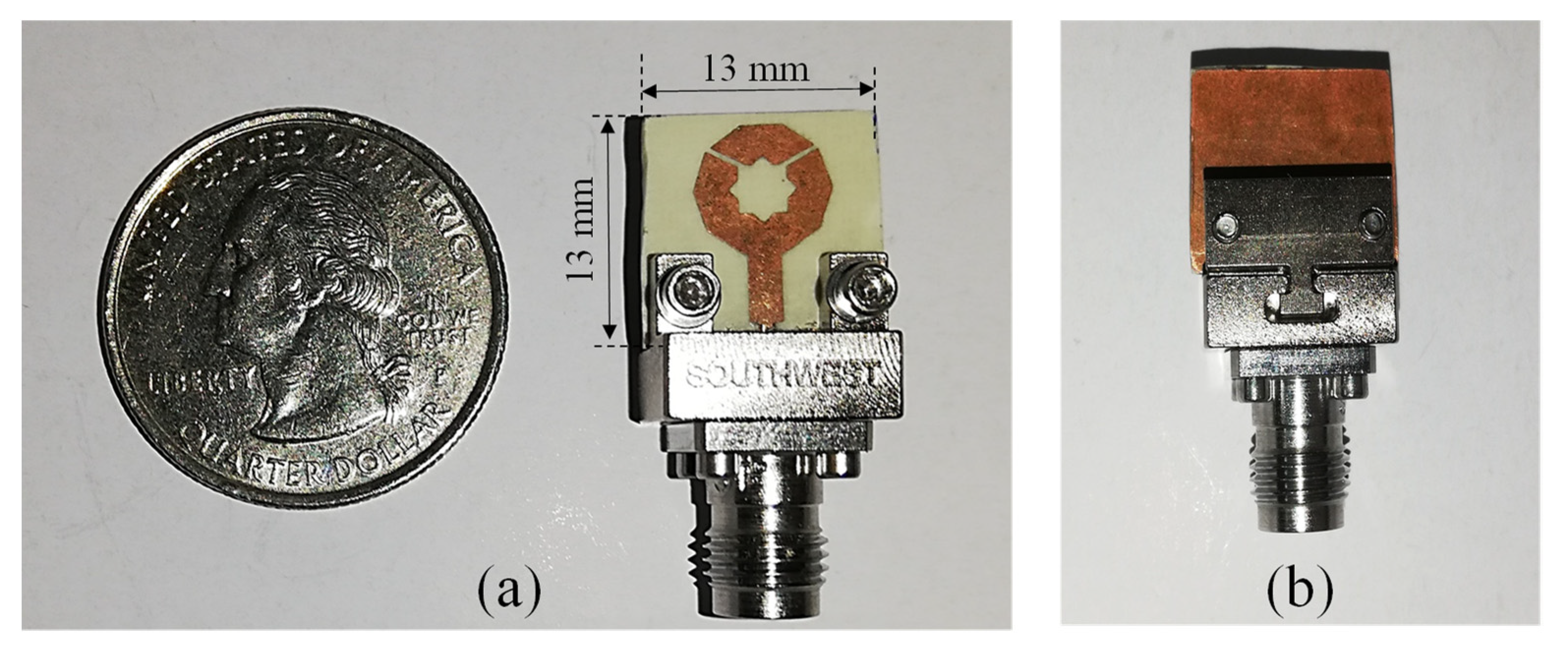
| Total area (mm2) (λ0 at 28 GHz) | 21.9 × 5.64 2.05 λ0 × 0.53 λ0 | 75 × 100 7 λ0 × 9.34 λ0 | 34 × 36 3.18 λ0 × 3.36 λ0 | ~ 40 × 40 3.74 λ0 × 3.74 λ0 | 48 × 67 4.48 λ0 × 6.26 λ0 | 13 × 13 1.21 λ0 × 1.21 λ0 | |
| Design type | Antipodal Vivaldi antenna | 2 × 2 Patch array | 2 × 2 Dual off-center-fed dipoles (array) | Magneto-electric dipole 1 × 2 array | Reconfigurable Leaky-wave antenna based on a HMSIW | Single element antenna based on decahedral geometry | |
| Reflection coefficient | −25 dB | ~−18 dB | ~−15 dB | ~−15 dB | ~−15 dB | −21.5 dB | |
| Impedance bandwidth | 4.66 GHz (28 GHz band) | 720 MHz (27.75–28.47 GHz) | 3 GHz (27.2–30.2 GHz) | 7 GHz (24.4–31.4 GHz) | 1.5 GHz (28–29.5 GHz) | 6.84 GHz (23.1–29.94 GHz) | |
| Gain | 3.4 dBi 3.6 dBi 7.4 dBi | 9.97 dBi 12.3 dBi | 13.1 dBi 13.2 dBi | 10 dBic | 8.2 ± 0.6 dBi | 6.56 dBi Average | |
| Polarization | N.A. | Linear | Dual linear | Circular | N.A. | Linear | |
| Radiation efficiency | >86% (28 GHz band) | >96% (28 GHz band) | 88% (28 GHz band) | N.A. | N.A. | >89.4% | |
| HPBW | 266° (E-plane) 160° (H-plane) | 29.9° (E-plane) 60.0° (H-plane) | 12° (xz-plane) 11° (yz-plane) | N.A. | 29° | 40° (E-plane) 65° (H-plane) | |
| Operation frequencies | 14.44–20.98 GHz 24.34–29 GHz 33–40 GHz | 5.9 GHz 28 GHz | 28 GHz 38 GHz | 28 GHz bands | 28 GHz band | 28 GHz bands | |
| Design complexity | high | low | high | high | medium | medium | |
| Fabrication | Easy | Easy | Difficult | Difficult | Easy | Easy | |
5. Conclusions
Author Contributions
Funding
Institutional Review Board Statement
Informed Consent Statement
Data Availability Statement
Conflicts of Interest
References
- Andrews, J.G.; Buzzi, S.; Choi, W.; Hanly, S.V.; Lozano, A.; Soong, A.C.K.; Zhang, J.C. What will 5G be? IEEE J. Sel. Areas Commun. 2014, 32, 1065–1082. [Google Scholar] [CrossRef]
- Attiah, M.L.; Isa, A.; Zakaria, Z.; Abdulhameed, M.; Mohsen, M.K.; Ali, I. A survey of mmWave user association mechanisms and spectrum sharing approaches: An overview, open issues and challenges, future research trends. Wirel. Netw. 2020, 26, 2487–2514. [Google Scholar] [CrossRef]
- Kumar, S.; Dixit, A.S.; Malekar, R.R.; Raut, H.D.; Shevada, L.K. Fifth Generation Antennas: A Comprehensive Review of Design and Performance Enhancement Techniques. IEEE Access 2020, 8, 163568–163593. [Google Scholar] [CrossRef]
- Guidelines for Evaluation of Radio Interface Technologies for IMT-2020; Document ITU-R M.2412-0; International Telecommunication Union: Geneva, Switzerland, 2017; pp. 1–144.
- Requirements, Evaluation Criteria and Submission Templates for the Development of IMT-2020; Document Report ITU-R M.2411-0; International Telecommunication Union: Geneva, Switzerland, 2017; pp. 1–32.
- Zhao, A.; Ren, Z. Wideband MIMO antenna systems based on coupled-loop antenna for 5G N77/N78/N79 applications in mobile terminals. IEE Access 2019, 7, 93761–93771. [Google Scholar] [CrossRef]
- Technical Feasibility of IMT in Bands Above 6 GHz; Document ITU-R M.2376-0; International Telecommunication Union: Geneva, Switzerland, 2015; pp. 1–134.
- Abdullah, M.; Altaf, A.; Anjum, M.R.; Arain, Z.A.; Jamal, A.A.; Alibakhshikenari, M.; Falcone, F.; Limiti, E. Future Smartphone: MIMO Antenna System for 5G Mobile Terminals. IEEE Access 2021, 9, 91593–91603. [Google Scholar] [CrossRef]
- Kiani, S.H.; Altaf, A.; Anjum, M.R.; Afridi, S.; Arain, Z.A.; Anwar, S.; Khan, S.; Alibakhshikenari, M.; Lalbakhsh, A.; Khan, M.A.; et al. MIMO Antenna System for Modern 5G Handheld Devices with Healthcare and High Rate Delivery. Sensors 2021, 21, 7415. [Google Scholar] [CrossRef]
- Khalid, H.; Awan, W.A.; Hussain, M.; Fatima, A.; Ali, M.; Hussain, N.; Khan, S.; Alibakhshikenari, M.; Limiti, E. Design of an Integrated Sub-6 GHz and mmWave MIMO Antenna for 5G Handheld Devices. Appl. Sci. 2021, 11, 8331. [Google Scholar] [CrossRef]
- Rappaport, T.S.; Xing, Y.; MacCartney, G.R.; Molisch, A.F.; Mellios, E.; Zhang, J. Overview of millimeter wave communications for fifth generation (5G) wireless networks with a focus on propagation models. IEEE Trans. Antennas Propag. 2017, 65, 6213–6230. [Google Scholar] [CrossRef]
- Xi, L. A wideband planar filtering dipole antenna for 5G communication applications. Microw. Opt. Technol. Lett. 2019, 61, 2746–2751. [Google Scholar] [CrossRef]
- Hussain, N.; Jeong, M.J.; Abbas, A.; Kim, T.J.; Kim, N. A metasurface-based low-profile wideband circularly polarized patch antenna for 5G millimeter-wave systems. IEEE Access 2020, 8, 22127–22135. [Google Scholar] [CrossRef]
- Zeng, J.; Luk, K.-M. Single-layered broadband magnetoelectric dipole antenna for new 5G application. IEEE Antennas Wirel. Propag. Lett. 2019, 18, 911–915. [Google Scholar] [CrossRef]
- Karthikeya, G.S.; Abegaonkar, M.P.; Koul, S.K. A wideband conformal antenna with high pattern integrity for mmWave 5G smartphones. Prog. Electromagn. Res. Lett. 2019, 84, 1–6. [Google Scholar] [CrossRef] [Green Version]
- Desai, A.; Upadhyaya, T.; Patel, R. Compact wideband transparent antenna for 5G communication systems. Mirow. Opt. Technol. Lett. 2019, 61, 781–786. [Google Scholar] [CrossRef]
- Alkaraki, S.; Andy, A.S.; Gao, Y.; Tong, K.-F.; Ying, Z.; Donnan, R.; Parini, C. Compact and low-cost 3-D printed antennas metalized using spray-coating technology for 5G mm-Wave communication systems. IEEE Antennas Wirel. Propag. Lett. 2018, 17, 2051–2055. [Google Scholar] [CrossRef]
- Yin, J.; Wu, Q.; Yu, C.; Wang, H.; Hong, W. Broadband endfire magnetoelectric dipole antenna array using SICL feeding network for 5G millimeter-wave applications. IEEE Trans. Antennas Propag. 2019, 67, 4895–4900. [Google Scholar] [CrossRef]
- Mujammami, E.H.; Sebak, A.B. Wideband high gain printed quasi-Yagi diffraction gratings-based antenna for 5G applications. IEEE Access 2019, 7, 18089–18100. [Google Scholar] [CrossRef]
- Dzagbletey, P.A.; Jung, Y.-B. Stacked microstrip linear array for millimeter-wave 5G baseband communication. IEEE Antennas Wireless Propag. Lett. 2018, 17, 780–783. [Google Scholar] [CrossRef]
- Goel, T.; Patnaik, A. Novel broadband antennas for future mobile communications. IEEE Trans. Antennas Propag. 2018, 66, 2299–2308. [Google Scholar] [CrossRef]
- Kim, E.; Ko, S.T.; Lee, Y.J.; Oh, J. Millimeter-wave tiny lens antenna employing U-shaped filter arrays for 5G. IEEE Antennas Wireless Propag. Lett. 2018, 17, 845–848. [Google Scholar] [CrossRef]
- Wen, B.J.; Peng, L.; Li, X.F.; Mo, K.S.; Jiang, X.; Li, S.M. A low profile and wideband unidirectional antenna using bandwidth enhanced resonance-based reflector for fifth generation (5G) systems applications. IEEE Access 2019, 7, 27352–27361. [Google Scholar] [CrossRef]
- Feng, B.; Li, L.; Zeng, Q.; Chung, K.L. A wideband antenna using metasurface for the 2G/3G/LTE/5G communications. Microw. Opt. Technol. Lett. 2018, 60, 2482–2487. [Google Scholar]
- Nadeem, I.; Choi, D.-Y. Study on mutual coupling reduction technique for MIMO antennas. IEEE Access 2019, 7, 563–586. [Google Scholar] [CrossRef]
- Sharawi, M.S.; Podilchak, S.K.; Khan, M.U.; Antar, Y.M. Dual frequency DRA-based MIMO antenna system for wireless access points. IET Microw., Antennas Propag. 2017, 11, 1174–1182. [Google Scholar] [CrossRef]
- Zhang, Y.; Deng, J.-Y.; Li, M.-J.; Sun, D.; Guo, L.-X. A MIMO dielectric resonator antenna with improved isolation for 5G mm-Wave applications. IEEE Antennas Wireless Propag. Lett. 2019, 18, 747–751. [Google Scholar] [CrossRef]
- Kowalewski, J.; Eisenbeis, J.; Jauch, A.; Mayer, J.; Kretschmann, M.; Zwick, T. A mmW broadband dual-polarized dielectric resonator antenna based on hybrid modes. IEEE Antennas Wirel. Propag. Lett. 2020, 19, 1068–1072. [Google Scholar] [CrossRef]
- Alibakhshikenari, M.; Khalily, M.; Virdee, B.S.; See, C.H.; Abd-Alhameed, R.A.; Limiti, E. Mutual Coupling Suppression between Two Closely Placed Microstrip Patches Using EM-Bandgap Metamaterial Fractal Loading. IEEE Access 2019, 7, 23606–23614. [Google Scholar] [CrossRef]
- Alibakhshikenari, M.; Khalily, M.; Virdee, B.S.; See, C.H.; Abd-Alhameed, R.A.; Limiti, E. Mutual-Coupling Isolation Using Embedded Metamaterial EM Bandgap Decoupling Slab for Densely Packed Array Antennas. IEEE Access 2019, 7, 51827–51840. [Google Scholar] [CrossRef]
- Jamshidi, M.B.; Roshani, S.; Talla, J.; Roshani, S.; Peroutka, Z. Size reduction and performance improvement of a microstrip Wilkinson power divider using a hybrid design technique. Sci. Rep. 2021, 11, 7773. [Google Scholar] [CrossRef]
- Roshani, S.; Roshani, S. A compact coupler design using meandered compact microstrip resonant cell (MLCMRC) and bended lines. Wirel. Netw. 2021, 27, 677–684. [Google Scholar] [CrossRef]
- Li, Y.; Sim, C.-Y.-D.; Luo, Y.; Yang, G. 12-port 5G massive MIMO antenna array in sub-6 GHz mobile handset for LTE bands 42/43/46 applications. IEEE Access 2018, 6, 344–354. [Google Scholar] [CrossRef]
- Medina, J.L.; Díaz, E.; Olera, J.L.; Chávez, R.A.; Velázquez, A. Análisis y Comparación de Metodologías Para Determinar Experimentalmente la Ganancia de Antenas de RF Y Microondas. In Proceedings of the Metrology Symposium, Querétaro, Mexico, 22 October 2008. [Google Scholar]
- Huber+Suhner. Formable Microwave Cable: SR_118_TP. Data Sheet. Available online: https://ecatalog.hubersuhner.com/media/documents/datasheet/en/pdf/22810073 (accessed on 26 May 2022).
- Ullah, R.; Ullah, S.; Faisal, F.; Ullah, R.; Choi, D.Y.; Ahmad, A.; Kamal, B. High-Gain Vivaldi Antenna with Wide Bandwidth Characteristics for 5G Mobile and Ku-Band Radar Applications. Electronics 2021, 10, 667. [Google Scholar] [CrossRef]
- Govindarajulu, S.R.; Hokayem, R.; Tarek, M.N.A.; Guerra, M.R.; Alwan, E.A. Low Profile Dual-Band Shared Aperture Array for Vehicle-to-Vehicle Communication. IEEE Access 2021, 9, 147082–147090. [Google Scholar] [CrossRef]
- Hu, H.; Lai, F.; Chen, Y. Dual-Band Dual-Polarized Scalable Antenna Subarray for Compact Millimeter-Wave 5G Base Stations. IEEE Access 2020, 8, 129180–129192. [Google Scholar] [CrossRef]
- Wang, Y.; Wu, B.; Zhang, N.; Zhao, Y.; Su, T. Wideband Circularly Polarized Magneto-Electric Dipole 1x2 Antenna Array for Millimeter-Wave Applications. IEEE Access 2020, 8, 27516–27523. [Google Scholar] [CrossRef]
- Javanbakht, N.; Amaya, R.E.; Shaker, J.; Syrett, B. Fixed Frequency Beam-Scanning HMSIW-Based Leaky-Wave Antenna Composed of Circular Slots in V-Shape Configuration. IEEE Access 2021, 9, 52891–52901. [Google Scholar] [CrossRef]


Publisher’s Note: MDPI stays neutral with regard to jurisdictional claims in published maps and institutional affiliations. |
© 2022 by the authors. Licensee MDPI, Basel, Switzerland. This article is an open access article distributed under the terms and conditions of the Creative Commons Attribution (CC BY) license (https://creativecommons.org/licenses/by/4.0/).
Share and Cite
Olan Nuñez, K.N.; Murphy Arteaga, R.S. A Novel and Compact Slotted-Decahedral Antenna for 5G Devices. Electronics 2022, 11, 1813. https://doi.org/10.3390/electronics11121813
Olan Nuñez KN, Murphy Arteaga RS. A Novel and Compact Slotted-Decahedral Antenna for 5G Devices. Electronics. 2022; 11(12):1813. https://doi.org/10.3390/electronics11121813
Chicago/Turabian StyleOlan Nuñez, Karen Nallely, and Roberto S. Murphy Arteaga. 2022. "A Novel and Compact Slotted-Decahedral Antenna for 5G Devices" Electronics 11, no. 12: 1813. https://doi.org/10.3390/electronics11121813