Article

Development of Enhanced Range, High Q, Passive, Chipless RFID Tags for Continuous Monitoring and Sensing Applications

1
Center for Wireless Networks & Applications (WNA), Amrita Vishwa Vidyapeetham, Amritapuri 690525, India
2
Department of Electronics and Communication Engineering, Amrita Vishwa Vidyapeetham, Amritapuri 690525, India
3
Department of Civil Environmental and Mechanical Engineering, University of Trento, 38123 Trento, Italy
*
Author to whom correspondence should be addressed.
Electronics 2022, 11(1), 127; https://doi.org/10.3390/electronics11010127
Submission received: 30 November 2021 / Revised: 24 December 2021 / Accepted: 28 December 2021 / Published: 31 December 2021
(This article belongs to the Special Issue Advances in Chipless RFID Technology)

Abstract

:
A high Q planar chipless RFID tag with high sensitivity is proposed for communication applications. In particular, the tag structure is composed of a complementary spiral structure (CSS) that is able to provide high sensitivity and compactness. A semi analytical formula for the design of a single bit tag is derived, and the behaviour of the CSS is analysed for different dielectric substrates. Different tags, composed of up to a set of eight resonators, have been numerically and experimentally assessed. In particular, a system prototype composed of a reader and a set of tags are fabricated and experimentally assessed as a proof of concept. The system provided an operative range of tens of centimetres (a maximum operative range of 65 cm). The obtained results are quite promising and the agreement between simulated and measured results are found to be good.

1. Introduction

Radio Frequency Identification and Detection (RFID) [1] is a well-consolidated technology successfully adopted for different applications [2,3,4,5,6]. In particular, RFID technology has many applications ranging from tracking foods and goods to the security of restricted areas [7,8,9,10,11,12,13,14,15,16]. Researchers are concentrated on finding solutions to further reduce the cost and in particular to improve the operating range [17,18,19,20,21,22], which for standard RFID is only a few centimeters. Some RFID systems permit us to obtain a large distance between the reader and the tags. However, they make use of a radio frequency front end and they require a power supply system or a battery to properly operate [23,24]. Another challenge is in the dimensions reduction that will permit us to open new operative scenarios and applications, such as wearable or implantable sensors [25,26,27,28]. One of the best solutions to reduce the dimensions of RFIDs and at the same time permits further cost reduction, is an approach that eliminates the presence of the chip, producing a tag that is called “chipless RFID” [29,30,31]. Chipless tags were demonstrated to be very versatile; they can be easily equipped with sensing capabilities while remaining extremely cheap, compact, and suitable for mass production since they can be fabricated with microstrip technology or printed directly on different dielectric substrates with suitable metallic inks. For all the above reasons, in the last few years, the scientific community has paid much attention to these types of tags.
Chipless RFIDs are usually based on two encoding mechanisms: the frequency-domain (FD) [32,33,34] and the time-domain (TD) [35,36,37]. Time domain sensors or tags make use of propagating structures designed to encode the information with suitable discontinuities. In particular, a discontinuity placed at defined positions encodes the bit value as 0 and its absence as 1. Usually, time domain tags are implemented by using a microstrip transmission line and a pulsed is used as interrogating signal that travels along the propagating structure such as a microstrip. A pulse is the interrogating signal that travels along the transmission line. The electromagnetic pulse which propagates through the microstrip gets reflected in the positions where there is a discontinuity. The reflections propagate back through the substrate, and retransmitted, and the reflections reach back to the reader. This principle is called time domain reflectometry. The problem of time domain tags and sensors is that they require very short pulse or a very long tags to avoid the overlapping between different echoes, produced by the discontinuities, which encode the information. Obtaining short pulses is not simple and it requires expensive generators. Moreover, a very long transmission line is mandatory to encode a large amount of data, the result is the loss of compactness versus the bit encoding capability. Frequency domain chipless tags are usually implemented by using multiple resonators tuned at different frequencies. The resonators are distributed to cover a given frequency band [38]. In this configuration, the interrogating signal must have a bandwidth that covers all the resonators’ frequencies. Resonators produce singularities in the amplitude and/or phase of the frequency response of the tag. Considering the simplest encoding method, each bit of information is represented by a single resonator. The presence of a resonator encodes the bit 0, while its absence represents the bit 1 [39]. In the frequency domain, to improve the wireless communication capabilities of the tag, sometimes cross polarized receiving and transmitting antennas are considered as in [40,41]. In this work, we will focus only on microwave RFID tag sensors based on the frequency domain because they are cheap, easy to fabricate, and more flexible. Spiral shaped passive chipless tags are used for the design of tags as they provide an enhanced transmission range, which makes it applicable for continuous monitoring and sensing applications. The design, implementation, real time testing and measurement of the RFID system for 4 bit and 8 bit RFID tags are discussed in detail in the paper.
This paper focuses on the design of a chipless RFID system, whose tags are based on planar spiral resonators [42,43]. The basic architecture of a RFID system consisting of reader and tag is detailed in Section 2. More details of the RFID reader and RFID tag are presented in Section 3 and Section 4, respectively. In particular, this paper proposed a simplified formula that permits the user to simplify the design of a resonator that aimed to encode a single bit. Thus, due to the compactness of the CSR, different tags have been designed, numerically and experimentally assessed to demonstrate the potentialities of the proposed system. A tag with eight different CSRs has been fabricated. The tag was equipped with microstrip antennas, with orthogonal polarisation. The details of the numeric and experimental testing and analysis are presented in Section 5. The experimental measurement campaign demonstrates that the proposed chipless tags based on CSR were able to reach an operative range up to 65 cm well above the standard chipless RFID system present in the scientific literature. Finally, Section 6 concludes the work.

2. Basic Architecture of RFID System

RFID systems belong to a group of technologies termed Automatic Identification and Data Capture (AIDC), which can be easily integrated in IoT systems. So, by using the AIDC technique, the RFID readers can directly sense the tags, capture the data and can be processed and analysed in an unsupervised way. RFID systems make use of low frequency electromagnetic signals, so they overcome the limitations of optical barcodes that require a perfect alignment to work properly. The coupling between the reader and the tags is usually obtained with an inductive coupling that require a short operative range to work properly. At the basic level, an RFID system consists of an RFID reader and RFID tags with antennas. A block diagram representation of the RFID system is shown in Figure 1.
The proposed chipless RFID system is composed of a reader and a set of tags. Each tag consists of multiple resonators, which aim to encode the bits, and transmitting and receiving antennas. The reader will be continuously sending electromagnetic waves to the RFID tags, using suitable direct digital signal generators (DDG). The signal will be received by the tag’s receiving antenna, propagated on a suitable transmission line (usually a microstrip) coupled with a series of resonators. The presence or absence of these resonators determines a response to the backscattered wave and consequently the specific ID of a certain item. In particular, the presence of a resonator introduces a resonance peak which encodes the 1 bit value. After passing through the resonators, the signal is retransmitted back to the reader by means of another suitable antenna placed in cross polarisation with respect to the tag’s receiving antenna to improve the signal to noise ratio (SNR). The receiving antenna at the reader receives the back-scattered signal, which identifies the unique code assigned to the RFID tag, by decoding the resonance peaks due to the spiral resonators.
The reader will be sending impinging electromagnetic signals of a specified frequency range towards the tag kept at a distance R from the reader, called operative range. The bandwidth of the impinging electromagnetic wave must cover all the resonance frequencies of the CSR which encode the tag’s code. The receiving antenna of the tag receive the interrogating electromagnetic wave, through the microstrip line and the signal passes through resonators, and finally it reaches a transmitting antenna, aligned in cross-polarization with respect to the receiving tag antenna. The transmitting antenna sends back to the reader the electromagnetic wave combined with the information provided by the resonators. It is worth noticing that the proposed chipless RFID systems does not use any low frequency electromagnetic wave as that requires an inductive coupling and will consequently result in a very low operative range. The system makes use of high frequency electromagnetic waves in the microwave frequency bands. This means that it is possible to estimate and eventually increase the operative range by considering the well known Friis transmission equation.
P R = P T G T G R λ 2 ( 4 π R ) 2
where P R is the received signal strength at the reader, P T is the power of the transmitted signal, G T and G R are the gain of the transmitting and receiving antennas, respectively, λ is the wavelength and R is the distance between the reader and the tag, the so called operative range R. In this work, the tag is made with a set of multi resonators directly coupled with a feeding microstripline. The transmitting and receiving antennas at the reader are broadband omnidirectional antenna with a bandwidth encompassing the frequencies of all the resonators. In particular, two log periodic antennas have been used in the reader section and are detailed in the next section.

3. RFID Reader Description

RFID Reader section consists of radio frequency front end section with a wide band antenna capable of decoding the receiving tag data. For our application, for testing standard log periodic antennas operating in the band 0.5–2 GHz is used [44].

4. CSR RFID Tag Description

The chipless RFID tag consists of a set of Complementary Spiral Resonators (CSRs) with ominidirectional wide band antennas for transmission and reception. Complementary spiral structure is chosen for the resonator design as it provides better performances with respect to a standard spiral resonator in terms of quality factor (Q) at lower frequencies. [45]. The designed filter provided a Q factor of 24 at 0.9636 GHz. The design of a single Complementary Spiral Resonator (CSR) is explained in detail in the below section.

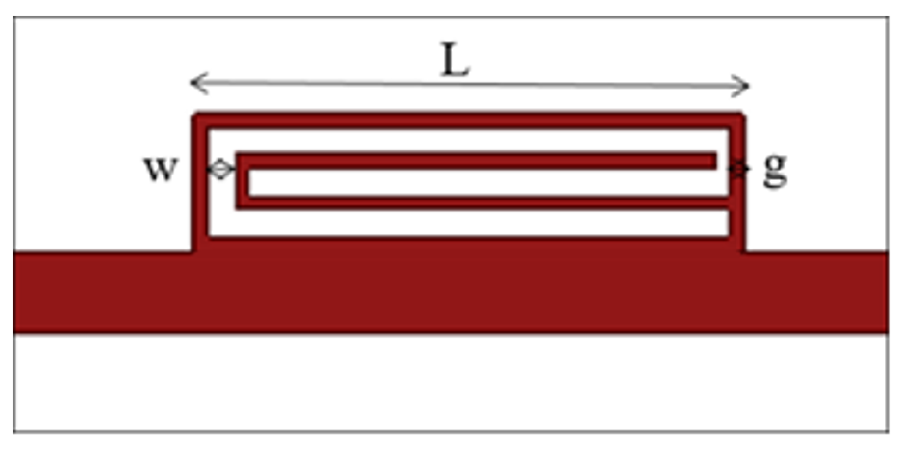
4.1. Design of Single Resonator Tag

This subsection is aimed at the design of a single CSR. The design of CSR starts from an extension of the feeding microstrip line as shown in Figure 2a by introducing a small segment of microstrip with an increased width as shown in Figure 2b. It is worth noticing that the structure reported in Figure 2b cannot act like a filter since it represents only an impedance discontinuity along the microstrip. In order to make the structure operate as a filter, a resonator able to encode information, a spiral shaped structure is etched from the section of the modified microstrip line as reported in Figure 2c. These complementary spiral structures (CSR’s) resonate at a particular frequency which can be easily tuned by acting on the spiral geometric parameters, as shown in Figure 3, which report the CSR structures and the related geometrical parameters that can be tuned to change the CSR resonance frequency.
The designed CSR is characterized by N sides, a length L, the width of the etched line is W and the width of the metallization is g as detailed in Figure 3.
Let us focus on the design of a simple CSR resonator. The effective permittivity, ε e is calculated by using the following relation:
ε e = ε r + 1 2 + ε r 1 2 1 + 12 h w ,
where ε r is the dielectric permittivity and h is the height of the dielectric substrate, w is the gap between of the spiral sides. The wavelength of the resonator, λ m is given by the equation which report the electrical length with respect to the considered dielectric substrate.
λ m = c f ε e ,
where c is the speed of light and f is the operating frequency. The total length L of the spiral resonator with N sides and width g can be estimated by using the following equation:
L = λ m ( N 1 ) g ( N + 1 ) 0.008515 c f .
The above relations (2)–(4) have been empirically derived by considering an extensive set of numerical simulations performed with a commercial electromagnetic software, namely ANSYS HFSS.
To assess the design Equations (2)–(4), an exhaustive analysis has been carried out for different frequency ranges and for different substrates. For the present assessment, reporting only a selected set of cases, in particular a CSR with N = 5, has been considered and fabricated on FR4 dielectric substrate ( ε r = 4.4 , t a n ( δ ) = 0.02 , h = 1.6 mm).
Without loss of generality, a CSR operating at 1.1 GHz, characterized by the following geometrical parameters: L = 24 mm, w = 1 mm and g = 1 mm in FR4 epoxy has been considered as a first experiment. A set of numerical simulations aiming to assess the frequency shifts with respect to the dielectric permittivity of the substrate have been carried out. The results of the analysis are reported in Figure 4. It is worth noticing that the error between the predictions given by Equation (4) is less than 4 % with respect to the simulated data obtained with a commercial software based on an FEM electromagnetic engine, namely ANSYS HFSS, demonstrating that the empirically derived Equations (2)–(4) are quite effective. The same CSR geometry has been fabricated and experimentally assessed with a Vector Network Analyzer, namely Keysight E 5080 A. For different values of operating frequency, the length of the resonator is calculated using the design Equation (4) and is validated using simulation software ANSYS HFSS which are approximately the same; the error is less than 4%. As can be noticed, the agreement between measured and simulated data is very good; also a small frequency shift of about 25 MHz can be observed from the data in Table 1. The frequency shift is probably due to the material tolerances.
The Q of a single bit resonator is given by the Equation (5) as in [45]:
Q = f 0 Δ f = f 0 f 2 f 1 ,
where f 0 is the center frequency and Δ f is the −10 dB bandwidth, which is chosen as the reference point for detection. In the literature, almost all the RFID tag designs are done at high frequencies and thus provide higher Q factor values. However, on looking into the low frequency tags, the designed spiral resonator provides a good Q factor value of 24 at 0.9636 GHz. Getting a high Q value of 24 at a frequency of less than 1 GHz proves the energy storing capacity and selectivity of the designed spiral resonator at the operating frequency and provides the least attenuation compared to other designs.
Using the same procedure, four resonators corresponding to four frequencies in the L band are considered for designing a 4-bit multi resonator tag using CSR, which is explained in the next sections.

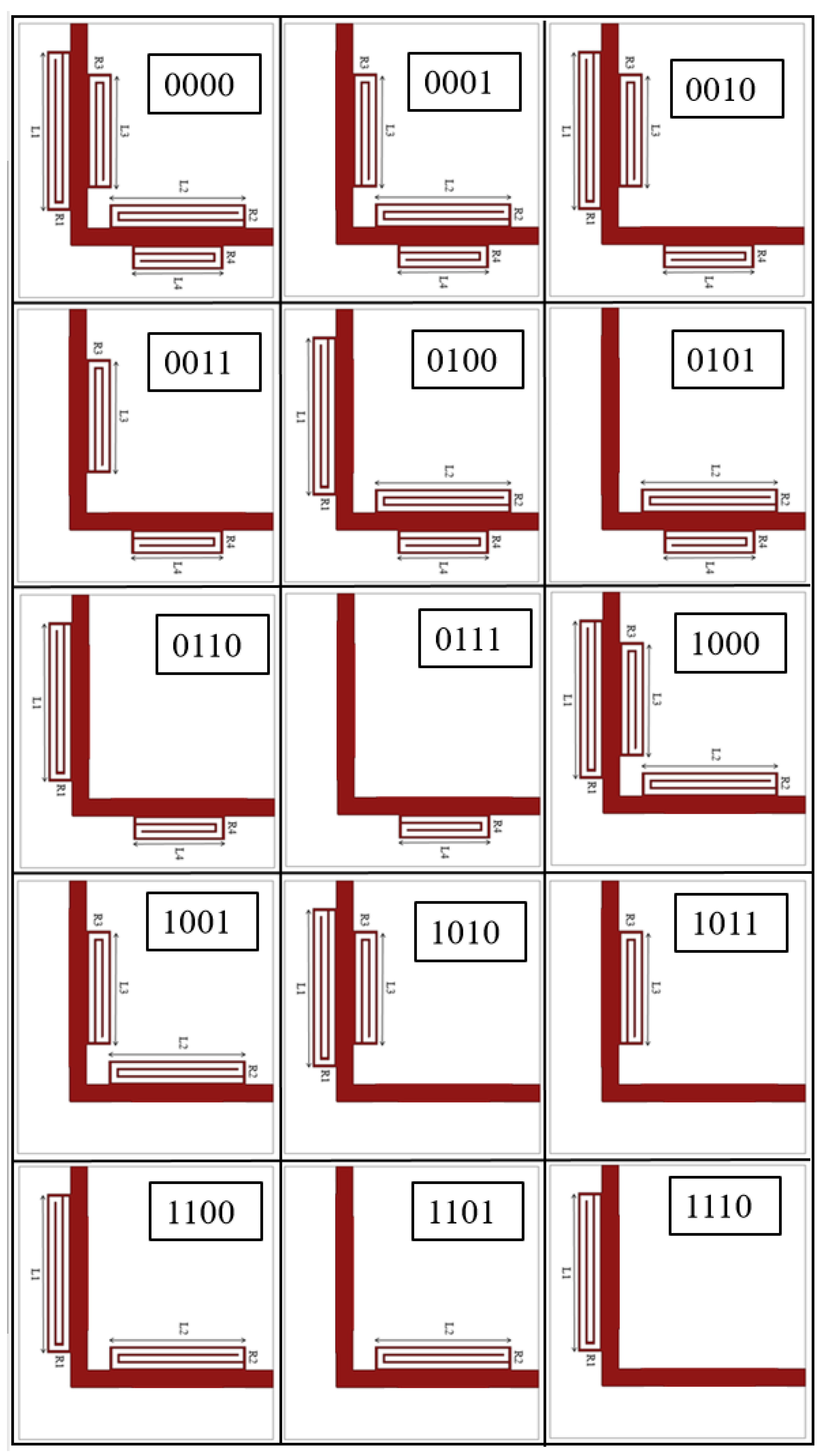
4.2. Design of Multi-Resonator Tags

The goal of the following experiment is to design a multibit chipless RFID tag in the L band (1–2 GHz). Six different CSR resonators, able to completely cover the L band with a frequency step of 200 MHz, are shown in Table 1. S 21 greater than −10 dB is kept as a threshold for object detection.
An n bit passive tag can detect ( 2 n 1 ) objects, so a 4 bit tag can detect only 15 objects and it is not suitable for commercial applications; however, a 4 bit tag is useful as a proof of concept to demonstrate the detection capabilities. Figure 5a,b shows the geometry of the considered 4 bits and 8-bits RFID tags respectively. A 90 degrees bend has been used to reduce the tag size and CSRs have been placed on both sides of the main microstrip. In particular, the CSR has been designed to resonate at f 1 = 0.97 GHz, f 2 = 1.13 GHz, f 3 = 1.35 GHz, f 4 = 1.69 GHz.
For the sake of completeness, all the combinations of the 4 bits tags have been numerically and experimentally assessed to correctly identify the unwanted couplings or cross resonance problems. The results are summarized in Table 2.
It can be noticed that all the considered configurations have a S 21 smaller than −12 dB in the simulation as well as in measurement, which ensures a good tag detectability. Concerning the considered bits encoding, each peak passing below the −10 dB threshold indicates the presence of a bit ‘0’; contrarily, the absence of the peak indicates the presence of bit ‘1’. Different tag configurations are presented in Figure 6. If all the resonators are present (resonator bits are high, R 4 = 1; R 3 = 1; R 2 = 1; R 1 = 1) the code word is 0000.
The last step to obtain a working RFID prototype is to include two antennas in the tag. In the next section, the design of omnidirectional broad band antennas is detailed.

4.3. Omnidirectional Wide Band Antenna

To complete the RFID tag together with the multiresonators, a transmitting and receiving antenna needs to be incorporated. This section deals with the design and analysis of an omnidirectional antenna performing in L-band.
An omnidirectional antenna with resonance encompassing the frequency of all multiresonators has been designed and fabricated. The broadband antenna consist of a rectangular patch antenna feeded at one corner with a microstrip line and on the back side a background of height h = 39 mm. The antenna dimensions are L = 48 mm, W = 75 mm. This antenna offers a 2:1 VSWR bandwidth from 0.83–1.99 GHz covering the whole frequencies of the tag. As it can be noticed the proposed antenna provide a S 11 < −10 dB in the whole L band. When this antenna is combined with the CSRs to implement an RFID tag, depending on the presence of the resonator, the antenna shows a notch behavior (due to the CSR which act like a stop band filter) in the frequency response. The picture of the designed antenna is shown in Figure 7 in the experimental setup.

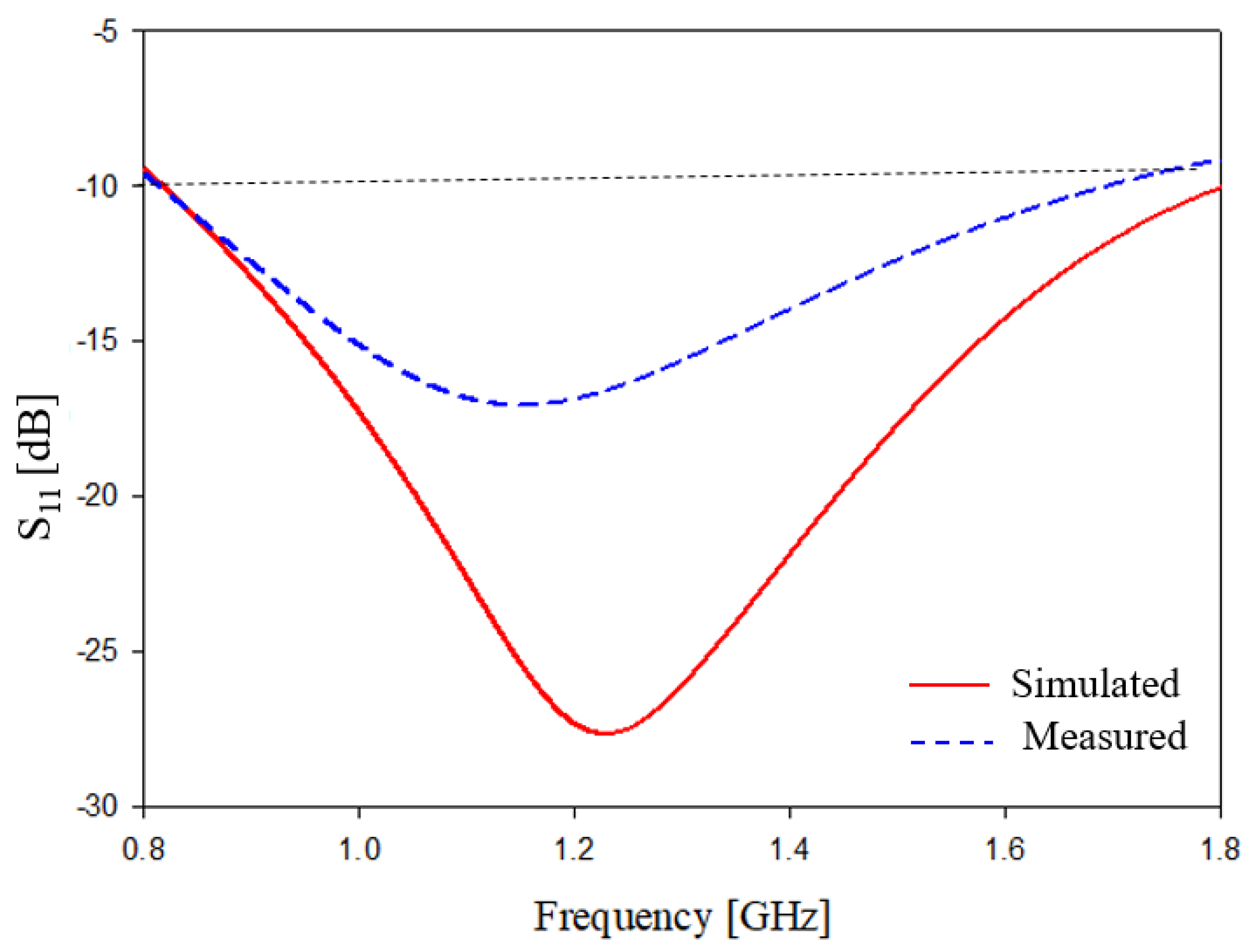
5. Numerical and Experimental Assessment

This section is aimed at numerically and experimentally assessing the proposed chipless RFID system; in particular, a set of tags composed of one, four and eight resonators, able to encode one, four, and eight bits, respectively, with a maximum of N = 256 possible combinations. The tags’ structures have been modelled and simulated by means of a commercial software, namely ANSYS HFFS. The tags were designed to operate in the L band microwave frequency range. The considered dielectric substrate is FR4 epoxy, ε r = 4.4 , thickness t = 1.6 mm, t a n ( δ ) = 0.02 . The geometrical parameters of the considered eight resonators are reported in Table 3, which also reports the correspondent resonating frequencies of each resonator.
To simulate the different tag combinations, a given resonator can be applied to or removed from the feeding microstrip. In particular, the presence of a resonator represents the bit “1”, characterized by a negative dip, while the absence of a resonator encodes the bit “0”. For almost all tag configurations, a simulation with HFSS has been carried out in order to simulate the signal received by the reader in the frequency range from 0.5 GHz to 2 GHz. In order to assess the capabilities of the proposed system, an experimental system prototype with different tags has been fabricated and assessed. The reader is a monostatic continuous wave radar (CW) simulated with a vector network analyzer (VNA), namely the Keysight E5080 A, which acts both as a sweep signal generator and as a receiver. The input–output ports of the VNA have been equipped with two broadband printed log periodic antennas, whose characteristics are reported in Table 4.
A photo of the considered experimental setup is reported in Figure 7, which shows the two LPDA antennas connected to the VNA and the RFID tag is placed in between the antennas. As it can be noticed, the experimental setup has been arranged in a simple laboratory without the necessity of a semi anechoic shielded room.
Concerning the tag prototypes, they are fabricated with a dielectric material FR4 ε r = 4.4 , thickness t = 1.6 mm, t a n ( δ ) = 0.02 . In particular, the photos of tag prototypes with one, four and eight spiral resonators are reported in Figure 8a–c respectively.
In order to compare the experimental measurements with the simulations obtained with the HFSS software, the resonators were coupled with a microstrip line. Each tag was equipped with two sub-miniature type A (SMA) coaxial connectors in order to connect two antennas, a transmitting and a receiving one, connected to the tag by means of the SMA coaxial connectors. The two antennas are placed in cross polarization in order to increase the signal to noise ratio (SNR). The receiving antenna aims to collect the impinging electromagnetic wave provided by the reader and to provide the excitation signals to the resonators, while the transmitting antenna aims to retransmit the electromagnetic wave, which encloses the data towards the reader. The geometrical characteristics and a photo of the tag antennas are reported in Table 5 and Figure 9, respectively.
The return loss parameter S 11 versus the frequency of the tag antennas is reported in Figure 10. As can be noticed, Figure 10 also reports a comparison between numerical data, obtained with HFSS, and experimental data. The agreement between numerical and experimental data is quite satisfactory and the tag antennas show S 11 below −10 dB in the whole considered frequency band. For the sake of completeness, the measured E and H planes beam pattern of the considered antennas are reported in Figure 11. As can be noticed from the results reported in Figure 11, the antennas show an omnidirectional beam pattern on the H plane.
For all of the following experiments, the experimental setup reported in Figure 7 has been considered and an operative range between the tags and the reader has been chosen equal to r = 0.65 m. The first experiment is related to a single bit tag, whose scattering parameters, measured and simulated, are reported in Figure 12.
As can be noticed from the S 21 data, the resonance peak is evident and the agreement between numerical and simulated data is quite satisfactory and only a slight frequency shift, probably due to the tolerances of the dielectric substrate, can be observed. In the second experiment, a four bits tag, whose geometry is reported in Figure 5a, has been considered. The tags prototype equipped with four CSR corresponds to the code 0000, and its response in terms of scattering parameters is reported in Figure 13, where the numerical data are compared with measured data. Additionally, in this experiment the resonance peaks are quite evident, despite the unideal environment characterized by a non free space and unshielded scenario. In the second experiment, a slight frequency shift between numerical and experimental data has also been observed. In the next experiment, different four bits tag configurations have been considered.
Figure 6 reports all the possible sixteen combinations while Figure 14a–c reports the results obtained with experimental prototypes characterized by the codes 0101, 0010 and 0000, respectively. The photos of the realized four bits prototypes with the related unique code are also reported in Figure 14a–c. As can be noticed from the results reported in Figure 14, all the codes are perfectly identified and the agreement between measured and experimental data is quite satisfactory. Figure 14d shows a photo of the VNA screen reporting the measurement of the tag with code 0000.
In the last experiment, a tag with eight bits that is able to encode 256 different combinations has been considered. The geometry and the photo of the prototype are reported in Figure 5b. The tag equipped with the two antenna by means of the SMA coaxial connector has been placed in front of the reader at an operative range r = 0.65 m as in the previous experiments. In particular, a tag equipped with all the eight CSRs and encoding the code 00000000 have been considered. The obtained experimental results, compared as usual with the numerical one, are reported in Figure 15. As can be noticed from the data in Figure 15, the eight resonance peaks are evident and well defined, the agreement between experimental and numerical data is quite satisfactory with only a slight frequency shift between numerical and experimental data.

6. Conclusions

The design, fabrication, numerical and experimental validation of a chipless RFID system based on CSRs has been described in this work. The system operates in the L band and it was able to reach a considerable operative range of about 0.65 m. In particular, different tag prototypes that are able to encode up to 8 bits (which can be easily increased) have been fabricated, assessed and served as proof of concept. The tags prototypes were able to retransmit the unique code represented by the CSRs with high efficacy; moreover they were demonstrated to be quite compact and easy to produce. The obtained results were very promising and they demonstrated the potentialities of the proposed chipless RFID system.

Author Contributions

Conceptualization, A.S., S.K.M. and M.D.; methodology, A.S. and S.K.M.; software, A.S.; validation, A.S. and S.K.M.; formal analysis, A.S., S.K.M. and M.D.; investigation, A.S., S.K.M. and M.D.; resources, A.S. and S.K.M.; data curation, A.S., S.K.M. and M.D.; writing original draft preparation, A.S.; writing review and editing, A.S., S.K.M. and M.D.; visualization, A.S., S.K.M. and M.D.; supervision, S.K.M. and M.D.; project administration, A.S. All authors have read and agreed to the published version of the manuscript.

Funding

This research received no external funding.

Acknowledgments

The authors are immensely grateful to our beloved Chancellor, Mata Amritanandamayi Devi, for the inspiration and motivation in the successful completion of the work. We would also like to thank Jolly Rajendran for the LPDA in taking measurements.

Conflicts of Interest

The authors declare no conflict of interest.

References

  1. Mulloni, V.; Donelli, M. Chipless RFID Sensors for the Internet of Things: Challenges and Opportunities. Sensors 2020, 20, 2135. [Google Scholar] [CrossRef] [Green Version]
  2. Finkenzeller, K. RFID Handbook, 2nd ed.; Wiley: New York, NY, USA, 2004. [Google Scholar]
  3. Finkenzeller, K. RFID Handbook: Fundamentals and Applications in Contactless Smart Cards, Radio Frequency Identification and Near-Field Communication; John Wiley & Sons: Hoboken, NJ, USA, 2010. [Google Scholar]
  4. Weinstein, R. RFID: A technical overview and its application to the enterprise. IT Prof. 2005, 7, 27–33. [Google Scholar] [CrossRef]
  5. Dobkin, D.M. The RF in RFID: Passive UHF RFID in Practice; Elsevier: New York, NY, USA, 2006. [Google Scholar]
  6. Capdevila, S.; Jofre, L.; Romeu, J.; Bolomey, J.C. Passive RFID based sensing. In Proceedings of the IEEE International Conference on RFID-Technologies and Applications, Orlando, FL, USA, 12–14 April 2011. [Google Scholar]
  7. Kanojia, V.; Kapoor, S.; Sidhu, G.K. Radio Frequency Identification (RFID): Basic Principles and Applications in the Food Industry. In Handbook of Research on Food Processing and Preservation Technologies; Apple Academic Press: Williston, VT, USA, 2021; pp. 3–19. [Google Scholar]
  8. Kumar, P.; Reinitz, H.W.; Simunovic, J.; Sandeep, K.P.; Franzon, P.D. Overview of RFID technology and its applications in the food industry. J. Food Sci. 2009, 74, R101–R106. [Google Scholar] [CrossRef]
  9. Sharif, A.; Kumar, R.; Ouyang, J.; Abbas, H.T.; Alomainy, A.; Arshad, K.; Assaleh, K.; Althuwayb, A.; Imran, M.A.; Abbasi, Q.H. Making assembly line in supply chain robust and secure using UHF RFID. Sci. Rep. 2021, 11, 18041. [Google Scholar] [CrossRef] [PubMed]
  10. Zaqumi, M.N.; Yousaf, J.; Zarouan, M.; Hussaini, M.A.; Rmili, H. Passive Fractal Chipless RFID Tags Based on Cellular Automata for Security Applications. Appl. Comput. Electromagn. Soc. J. 2021, 36, 542–547. [Google Scholar] [CrossRef]
  11. Mondal, S.; Kumar, D.; Chahal, P. Recent Advances and Applications of Passive Harmonic RFID Systems: A Review. Micromachines 2021, 12, 420. [Google Scholar] [CrossRef] [PubMed]
  12. Hassania Rouan, E.; Boumezzough, A. RFID Based Security and Automatic Parking Access Control System. In International Conference on Business Intelligence; Springer: Cham, Switzerland, 2021; pp. 434–443. [Google Scholar]
  13. Raza, S.A. A systematic literature review of RFID in supply chain management. J. Enterp. Inf. Manag. 2021. [Google Scholar] [CrossRef]
  14. Chowdhury, B.D.B.; Masoud, S.; Son, Y.J.; Kubota, C.; Tronstad, R. A Dynamic HMM-based Real-time Location Tracking System Utilizing UHF Passive RFID. Available online: https://ieeexplore.ieee.org/abstract/document/9508353 (accessed on 1 December 2021).
  15. Sundaram, B.R.; Vasudevan, S.K.; Aravind, E.; Karthick, G.; Harithaa, S. Smart car design using RFID. Indian J. Sci. Technol. 2015, 8, 1–5. [Google Scholar] [CrossRef]
  16. Prasanth, V.; Soman, K.P. Ticketing solutions for Indian railways using RFID technology. In Proceedings of the 2009 International Conference on Advances in Computing, Control, and Telecommunication Technologies, Trivandrum, India, 28–29 December 2009; pp. 217–219. [Google Scholar]
  17. Oliveira, N.R.D.; Boaventura, L.P.; Ferreira, T.N.; Magri, V.P.; Pereira, J.S.; Mattos, D.M. A Low Cost, High-Reliability Receiver System for Reading Passive RFID Tags. J. Microwaves Optoelectron. Electromagn. Appl. 2021, 20, 812–822. [Google Scholar] [CrossRef]
  18. Rennane, A.; Benmahmoud, F.; Cherif, A.T.; Touhami, R.; Tedjini, S. Design of Autonomous Multi-Sensing Passive UHF RFID tag for Greenhouse Monitoring. Sens. Actuators A Phys. 2021, 331, 112922. [Google Scholar] [CrossRef]
  19. Prabavathi, P.; Subha Rani, S. Flower shaped frequency coded chipless RFID tag for low cost item tracking. Analog. Integr. Circuits Signal Process. 2021, 109, 79–91. [Google Scholar] [CrossRef]
  20. Sharif, A.; Ouyang, J.; Arshad, K.; Imran, M.A.; Abbasi, Q.H. Passive UHF RFID Tag Antennas-Based Sensing for Internet of Things Paradigm. In Backscattering and RF Sensing for Future Wireless Communication; 2021; Available online: https://www.semanticscholar.org/paper/Passive-UHF-RFID-Tag-Antennas (accessed on 1 December 2021).
  21. Donelli, M. Design of long-range, powerless RFID sensor at 10 GHz. Electron. Lett. 2013, 49, 1277–1278. [Google Scholar] [CrossRef]
  22. Donelli, M. Guidelines for the Design and Optimization of Wireless Sensors Based on the Modulated Scattering Technique. IEEE Trans. Instrum. Meas. 2014, 63, 1824–1833. [Google Scholar] [CrossRef]
  23. Dobrykh, D.; Yusupov, I.; Mikhailovskaya, A.; Krasikov, S.; Shakirova, D.; Bogdanov, A.; Slobozhanyuk, A.; Filonov, D.; Ginzburg, P. High-Permittivity Ceramic Tags Miniaturization for Long-Range RFID Applications. In Proceedings of the 2021 15th European Conference on Antennas and Propagation (EuCAP), Düsseldorf, Germany, 22–26 March 2021; pp. 1–4. [Google Scholar]
  24. Galko, I.; Kuffa, R.; Magdolenová, P.; Svetlík, J.; Veľas, A. RFID tags at the operation of fire stations. Transp. Res. Procedia 2021, 55, 941–948. [Google Scholar] [CrossRef]
  25. Rahmat-Samii, Y.; Song, L. Advances in Communication and Biomedical Antenna Developments at the UCLA Antenna Lab: Handheld, Wearable, Ingestible, and Implantable [Bioelectromagnetics]. IEEE Antennas Propag. Mag. 2021, 63, 102–115. [Google Scholar] [CrossRef]
  26. Hassan, M.; Abbas, G.; Li, N.; Afzal, A.; Haider, Z.; Ahmed, S.; Xu, X.; Pan, C.; Peng, Z. Significance of Flexible Substrates for Wearable and Implantable Devices: Recent Advances and Perspectives. Adv. Mater. Technol. 2021. [Google Scholar] [CrossRef]
  27. Ghosh, J.; Gopinath, S.; Chinmay, C. Smart Health Care for Societies: An Insight into the Implantable and Wearable Devices for Remote Health Monitoring. Green Technol. Innov. Sustain. Smart Soc. 2021, 12, 89–113. [Google Scholar]
  28. Hasni, U.; Piper, M.E.; Lundquist, J.; Topsakal, E. Screen-Printed Fabric Antennas for Wearable Applications. IEEE Open J. Antennas Propag. 2021, 2, 591–598. [Google Scholar] [CrossRef]
  29. Preradovic, S.; Karmakar, N.C. Multiresonator-Based Chipless RFID: Barcode of the Future; Springer: New York, NY, USA, 2012; ISBN 978-1-4614-2094-1. [Google Scholar]
  30. Mc Gee, K.; Anandarajah, P.; Collins, D. A Review of Chipless Remote Sensing Solutions Based on RFID Technology. Sensors 2019, 19, 4829. [Google Scholar] [CrossRef] [Green Version]
  31. Herrojo, C.; Paredes, F.; Mata-Contreras, J.; Martín, F. Martín Chipless-RFID: A Review and Recent Developments. Sensors 2019, 19, 3385. [Google Scholar] [CrossRef] [Green Version]
  32. Islam, M.A.; Karmakar, N.C. A dual polarised universal reader for frequency domain-based chipless RFID tags and sensors. IET Microwaves Antennas Propag. 2021, 15, 342–355. [Google Scholar] [CrossRef]
  33. Liu, Y.; Yang, X. Chipless Radio Frequency Identification Tag Design with Modified Interdigital Hairpin Resonators. In Proceedings of the 2018 International Conference on Intelligent Transportation, Big Data Smart City (ICITBS), Xiamen, China, 25–26 January 2018; pp. 645–648. [Google Scholar]
  34. Bibi, T.; Khan, A.T.; Amin, Y.; Ahmed, S. RFID in IoT, Miniaturized Pentagonal Slot-based Data Dense Chipless RFID Tag for IoT Applications. Arab. J. Sci. Eng. 2021, 2, 1–11. [Google Scholar] [CrossRef]
  35. Forouzandeh, M.; Karmakar, N.C. Chipless RFID tags and sensors: A review on time-domain techniques. Wirel. Power Transf. 2015, 2, 62–77. [Google Scholar] [CrossRef]
  36. Ghiri, R.E.; Entesari, K. Time-domain Ultra-wideband Chipless RFID Readers. IEEE Trans. Instrum. Meas. 2021, 23, 12–17. [Google Scholar]
  37. Barbot, N.; Etienne, P. Linear Time-Variant Chipless RFID Sensor. IEEE J. Radio Freq. Identif. 2021, 32, 22–27. [Google Scholar] [CrossRef]
  38. Vinod, A.; Aiswarya, S.; Meenu, L.; Menon, S.K. Design and analysis of planar resonators for wireless communication. In Proceedings of the 2020 5th International Conference on Communication and Electronics Systems (ICCES), Coimbatore, India, 10–12 June 2020; pp. 375–380. [Google Scholar]
  39. Aiswarya, S.; Sreerag, C.; Aravind, A.; Menon, S.K. Microstrip multiple resonator assisted passive RFID tag for object tracking. In Proceedings of the 2017 2nd International Conference on Communication and Electronics Systems (ICCES), Piscataway, NJ, USA, 19–20 October 2017; pp. 752–756. [Google Scholar]
  40. Sharma, V.; Hashmi, M. Chipless RFID tag based on open-loop resonator. In Proceedings of the 2017 IEEE Asia Pacific Microwave Conference (APMC), Kuala Lumpur, Malaysia, 13–16 November 2017; pp. 543–546. [Google Scholar]
  41. Chen, C.; Chen, Y.; Li, T.; Yu, Y.; Wu, W. A chipless RFID system based on polarization characteristics. In Proceedings of the 2017 7th IEEE International Symposium on Microwave, Antenna, Propagation, and EMC Technologies (MAPE), Xi’an, China, , 24–27 October 2017; pp. 324–329. [Google Scholar]
  42. Iswarya, S.; Ranjith, M.; Menon, S.K. Passive RFID tag with multiple resonators for object tracking. In Proceedings of the 2017 Progress in Electromagnetics Research Symposium-Fall (PIERS-FALL), Singapore, 19–22 November 2017; pp. 742–746. [Google Scholar]
  43. Karthik, A.; Aiswarya, S.; Menon, S.K. Compact low cost passive rfid tag for object tracking. In Proceedings of the 2018 International Conference on Advances in Computing, Communications and Informatics (ICACCI), Bangalore, India, 19–22 September 2018; pp. 1711–1714. [Google Scholar]
  44. Chopade, P.; Gaikwad, S.V. Design and Analysis of Log Periodic Dipole Array Antenna. ICTACT J. Microelectron. 2019, 5, 836–844. [Google Scholar]
  45. Shahmohammadi, M.; Chabalko, M.; Sample, A.P. High-Q, over-coupled tuning for near-field RFID systems. In Proceedings of the 2016 IEEE International Conference on RFID (RFID), Foshan, China, 21–23 September 2016; pp. 1–8. [Google Scholar]
Figure 1. Schematic of an RFID system.
Electronics 11 00127 g001
Figure 2. Microstrip line modified to filter with CSR (a) microstrip line (b) high impedance line loaded microstrip line (c) Complementary Spiral Resonator (CSR) loaded microstrip line.
Electronics 11 00127 g002
Figure 3. Geometry of single bit RFID tag resonator.
Electronics 11 00127 g003
Figure 4. Validation of design equation for CSR.
Electronics 11 00127 g004
Figure 5. (a) Geometry of RFID tag resonator 4 bit (b) 8 bit.
Electronics 11 00127 g005
Figure 6. Resonators configurations for a 4 bits chipless tag.
Electronics 11 00127 g006
Figure 7. Measurement setup of passive 4 bits CSR tag.
Electronics 11 00127 g007
Figure 8. Prototype fabricated on FR-4 epoxy (a) single bit RFID tag resonator (b) 4 bit RFID tag (c) 8 bit RFID tag.
Electronics 11 00127 g008
Figure 9. Fabricated prototype of omnidirectional wide band antenna on FR-4 epoxy (a) Top view (b) Bottom view.
Electronics 11 00127 g009
Figure 10. Numerical results antenna return loss S 11 .
Electronics 11 00127 g010
Figure 11. Measured radiation pattern of antenna.
Electronics 11 00127 g011
Figure 12. Frequency Response of CSR.
Electronics 11 00127 g012
Figure 13. Frequency Response of 4 bit CSR with code 0000.
Electronics 11 00127 g013
Figure 14. (a) Frequency Response for tag with code 0101 (b) Frequency Response for tag with code 0010 (c) Frequency Response for tag with code 0000 (d) Measurement setup of 4-bit tag (0000).
Electronics 11 00127 g014
Figure 15. Frequency Response for 8 bit tag with code 00000000.
Electronics 11 00127 g015
Table 1. Analysis of CSR for RFID tag.
Frequency,
f c [GHz]
Calculated Length,
L [mm]
Simulated Frequency,
f s [GHz]
Simulated S 21
[ dB ]
% Error
1.028.09910.9636−153.64
1.223.38261.1616−133.20
1.420.01371.3879−150.86
1.617.48701.6141−150.88
1.815.52171.7838−150.90
2.013.94962.0101−170.50
Table 2. Look up table for 4-bit CSR tag.
Number of
Objects
Resonators
Used
Frequency
[GHz]
S 21 [dB]Bit Sequence
(Code Word)
Output Bit
Sequence
1R10.9749−1600011110
2R21.1622−1600101101
3R1, R21.0017−2000111100
1.1335−16
4R31.3495−1501001011
5R1, R30.9883−1401011010
1.3424−15
6R2, R31.1355−1901101001
1.3495−15
7R1, R2, R30.9816−1701111000
1.1288−18
1.3361−13
8R41.704−1610000111
9R1, R40.9682−1710010110
1.6973−18
10R2, R41.1154−1410100101
1.6906−14
11 0.9682−2110110100
R1, R2, R41.1288−14
1.6906−16
12R3, R41.3495−1711000011
1.7241−17
13R1, R3, R40.9682−1511010010
1.3428−15
1.7107−19
14R2, R3, R41.1689−1711100001
1.3495−17
1.6906−16
15R1, R2, R3, R40.9615−1811110000
1.1355−17
1.3562−15
1.6973−17
Table 3. Geometrical parameters of 8 bit RFID tag.
ResonatorLength of Resonator [mm]Operating Frequency [GHz] S 21 [dB]
R140.00.6543−15
R235.40.7525−11
R331.40.8998−15
R427.40.9980−17
R524.01.1032−15
R620.01.3487−14
R717.01.5661−23
R815.41.6784−19
Table 4. Characteristics of LPDA.
ParameterValues
Bandwidth0.5–2 GHz
VSWR2:1
PolarisationLinear
Radiation patternDirectional
Table 5. Transmitter and receiver antenna characteristics of RFID tag.
ParameterValues
Resonance frequency1.2 GHz
Bandwidth0.8–1.8 GHz
Reflection Coefficient−28
VSWR2:1
Read range65 cm
Radiation patternOminidirectional
Publisher’s Note: MDPI stays neutral with regard to jurisdictional claims in published maps and institutional affiliations.

