1. Introduction
In the last years, chipless radio frequency identification solutions have been proposed as a frontier technology between two leaders of the sector: the chip-based RFID and the optical barcode. The ambition of chipless RFIDs is to merge in a unique technology the advantages brought by chipped RFIDs and by barcodes, overcoming thus their less functional characteristics. For this reason, chipless RFID systems are generally composed of a passive tag and a readout architecture that exploit non-line-of-sight wireless principles to communicate. This is for sure the greatest advantage that chipless RFIDs have when compared to barcodes. At the same time, the prices of barcodes are attractive for the market if compared with those of chipped RFID tags. Chipped RFIDs indeed require application-specific integrated circuit (ASIC) chips to store the identification information, which results in preventing their use in industrial applications where the cost of tags is comparable with the cost of goods. For this reason chipless RFID investigators aim at finding a solution in this sense and simplify the tag manufacture process encoding the identification information directly in the physical structure of the tag without the use of silicon chips. The fabrication process is thus made simpler and compatible with low-cost mass production printing strategies [
1,
2]. Moreover, the passive tag can be impressed directly on the product surface becoming a remotely readable non-invasive label.
However, as with all good stories, this technology will reach a more mature stage but is yet under development with some clear open challenges. A typical chipless RFID tag is composed of conductive resonators on a dielectric substrate and the information is encoded in the resonance peaks that they generate in the time or frequency domain. The absence of a silicon chip affects their performance in terms of coding capability and reading distance [
3]. The coding capability is strongly connected to the number of resonance structures the tag is able to physically host. In this sense, the research trend is looking at miniaturizing the resonance geometries in order to increase the number of coding structures in the tag without losing signal quality [
4,
5]. At the same time, chipless tags rely only on backscattering mechanisms to activate the tag and impress the ID signature in the response signal, and this is not the optimal way to reach long reading distances. Therefore, another current trend is searching for mechanisms to increase the remote interrogation capability since looking at them as completely passive labels is attractive for particular application fields, such as harsh environments [
6,
7]. Finally, the last trend is trying to investigate the potential use of chipless RFID as smart labels by combining their identification feature with sensing properties [
8,
9]. This last field is the particular area of interest to the current work.
Focusing on frequency-domain encoders, they can be turned into sensors by adding a suitable layer of sensing material covering the metallic resonance structures. This layer interacts with a specific physical parameter or chemical substance present in the environment and modifies accordingly the amplitude and the frequency of the encoding resonance peak. Despite the great opportunities introduced by the first prototypes reported in the literature for RFID chipless sensors, they are at the very first stages and much effort must be spent in this direction yet. The first problem is that the target is generally to detect and monitor changes due to a unique parameter. However, sensitive materials are usually affected by the presence of water particles in the air, which distorts the results and leads to an incorrect interpretation of the final data [
10,
11]. Therefore, the first focus in the chipless sensor area should be to finitely characterize chipless humidity probes, which should guide in quantifying the real impact of other chipless sensing signatures. The starting point for efficient sensor design is to screen for a well-performing sensing material or mechanism. Studies on chipless sensors for relative humidity (RH) detection have widely investigated the performance of sensitive materials such as polyvinyl-alcohol (PVA), Kapton or even common paper considering, in this case, the substrate as the sensing component [
12,
13,
14,
15]. In this work, the sensitive material we considered is a polymer well-known by experts of the fuel cells area, but it is probably the first time it is investigated in the chipless humidity sensing context. This material is Nafion 117 and one of our previous studies [
16] has already produced some satisfactory results demonstrating Nafion 117 is a very good candidate for humidity sensing. Indeed, from Nafion 117 studies [
12,
17] it is outlined that it has a great affinity to water and is far more sensitive than Kapton, which has a lower dielectric properties variation with respect Nafion 117, while if compared to PVA and common paper Nafion 117 shows better mechanical properties and works in an absolutely reversible way.
What we are proposing here will be a general validation of a Nafion 117-based chipless sensor targeted for low-humidity conditions. Low-humidity sensors are essential in several applications such as storage of medicine or pharmaceutical products, low moisture foods (LMF), or general products stored in an inert environment where moisture infiltration is critical. In particular, we will demonstrate that in this humidity range a substrate characterized by a low-dielectric constant is expected to perform better, in terms of sensitivity, than high-dielectric constant substrates. The study exploits the sensor proposed as an example in order to present an opportunity for discussion on the mutual impact the substrate and the sensing material have on the final sensitivity performance of chipless sensors. What is supported is that the contribution in the frequency signature of the sensitive material can be maximized by properly choosing the substrate based on the dielectric properties of the sensitive material while sensing. The idea supported can then become a useful and valid principle in the design phase of sensing material-based chipless encoders. The paper is organized as follows: in
Section 2 the theoretical explanation supporting the choice of the substrate is presented along with some simulation data, in
Section 3 the characterization of a low-humidity chipless sensor is provided with some experimental tests, and finally, in
Section 4 some last conclusions are drawn.
2. Materials and Methods
The main component of the encoding structure is a microstrip resonator which generates narrow resonance peaks in the microwave frequency regime when excited by a suitable electromagnetic wave. The performance of these conductive resonators are strongly dependent on two quantities, the resonant geometry design with particular interest to its design length and the dielectric permittivity of the RF substrate. Moreover, in the case of chipless sensors, also the presence of a sensitive layer impacts the nominal behavior and must be considered in the design phase. Generally speaking, for a resonator gap-coupled with a 50
-microstrip transmission line as in
Figure 1 all these influences can be enclosed in the following formula taken from [
18]:
where
is the first resonance frequency generated by the resonant geometry,
c is the light velocity,
is the resonator length and
is the effective dielectric constant that in our case is a variable of prime importance. Indeed, the effective dielectric constant includes the effects due to the dielectric substrate and those due to the sensitive layer.
Here we assume of having already selected a well-performing resonant geometry for sensing purposes (in our case an electric-field-coupled (ELC) resonator according to [
17]) and we try to go a step further. As seen in [
16] and re-proposed in
Table 1, when RH levels are low Nafion 117 tends to be characterized by medium dielectric constant
and low loss tangent
values. When instead Nafion 117 starts to incorporate more water both of them increase due to the dielectric properties of water, but the effects due to the change of loss tangent value dominate. Moreover, by the electromagnetic simulations and experimental tests of study reported in [
16], it is possible to understand that for high-humidity levels the resonance peak is much shifted in frequency due to higher dielectric constant values, but it appears particularly broadened due to the dominant high loss tangent values. On the other hand, for low-humidity levels, the sensor response is dominated by the variation of
of Nafion 117, which causes the frequency shift while the peak remains extremely sharp thanks to the low loss tangent values.
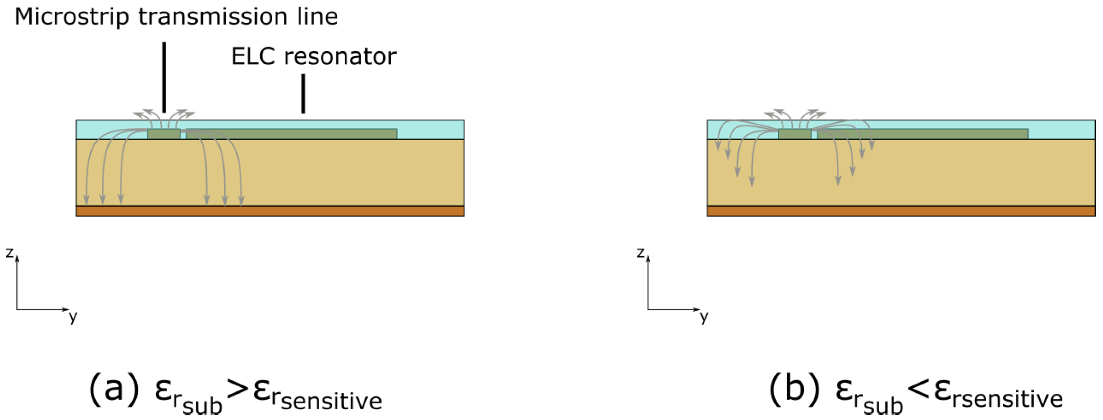
Here we will focus on this last case, proposing a strategy to increase the sensitivity of chipless sensors in low-humidity regimes. Only low RH values are considered in order to work in a condition of sharp resonance peaks. Our idea is that a substrate with low
can increase the sensitivity of the whole configuration compared to a substrate with high
. The physical explanation for this behavior can be found in the microstrip transmission line theory, precisely in the way the electric field propagates and diffuses into the dielectric surrounding the microstrip line and the resonator (
Figure 2) [
20]. As already mentioned,
is a combination of the values of the sensing material and the substrate. When the substrate has a high
, the electric field lines are more bent towards the substrate and, consequently, the contribution of the substrate to the effective dielectric constant is high and the contribution of the sensing material is low. In this case, the sensitivity in terms of frequency shift of the sensor results to be drastically reduced. Conversely, using a substrate with a low
, the contribution of the sensing material to the effective dielectric constant is more important, and the frequency shift and sensitivity higher.
In order to support our paper, we performed a set of simulations with the Ansys High Frequency Structure Simulator (HFSS). The ELC resonator design is the same reported in [
16], and a comparison among a higher dielectric constant substrate Rogers RO4003 (
,
10 GHz, thickness of
mm) used in [
16] and a lower dielectric constant substrate DiClad (
,
10 GHz, thickness of
mm) is proposed for low-humidity levels (<35%). The substrates have been chosen since they are comparable in terms of thickness and loss tangent value in order to understand the impact of their relative permittivity. Since according to Equation (
1) a change of substrate (and therefore of
) would generate a resonance peak of the ELC resonator at a different frequency, we have properly scaled the resonator dimensions on the DiClad substrate match the resonance peak frequency of simulations in [
16]. Its final size on DiClad are 13.4 × 13.4 mm
. After this calibration process, a 150
m thick-Nafion 117 layer was added to the configuration. The dielectric parameters of Nafion 117 (
Table 1) used as in [
16] are related to different RH conditions measured at 25 °C. In the table the variable
indicates the average number of water molecules surrounding the sulfonic group in the polymeric structure of Nafion 117 and a rough correspondence with the RH level is also proposed from [
19].
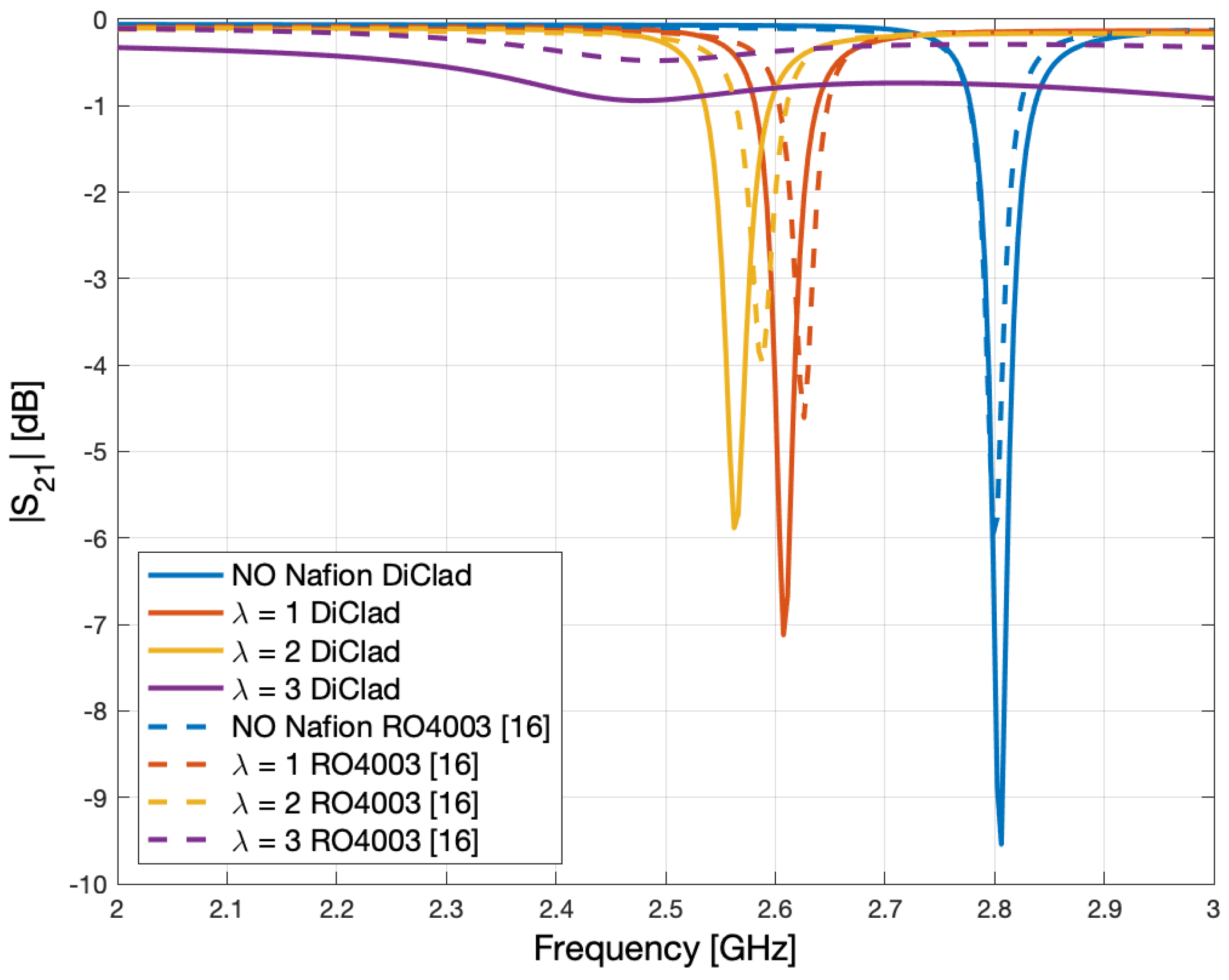
The results of the simulation process for DiClad are compared in
Figure 3 with those of Rogers RO4003 of [
16]. From the plot it is possible to appreciate the initial calibration process of the ELC resonator on the two substrates, which has been performed in order to start having them resonating at the same resonance frequency of 2.8 GHz without Nafion 117. Even though the difference in the
of the two substrates is not very large, the different frequency shift of the resonance peak is well visible from the simulation. A more pronounced frequency shift is generated by the lowest relative permittivity substrate DiClad, which results in a higher sensitivity sensor.
3. Results
Since from the previous section, simulations supported the idea that for low or very low RH measurements, using a substrate with an
as low as possible is the best choice, the sensor on DiClad has been fabricated and tested in order to propose a better candidate for low-humidity measurements. The sensing configuration has been fabricated by CNC milling, equipped with Sub-Miniaturize type A (SMA) connectors and placed in a climatic chamber as in [
16]. Its S-parameters have been properly monitored by means of a vector network analyzer (VNA) connected via RF cables to the sensor. The climatic chamber has been set up to work at a fixed temperature (25 °C) and humidity up to 45%.
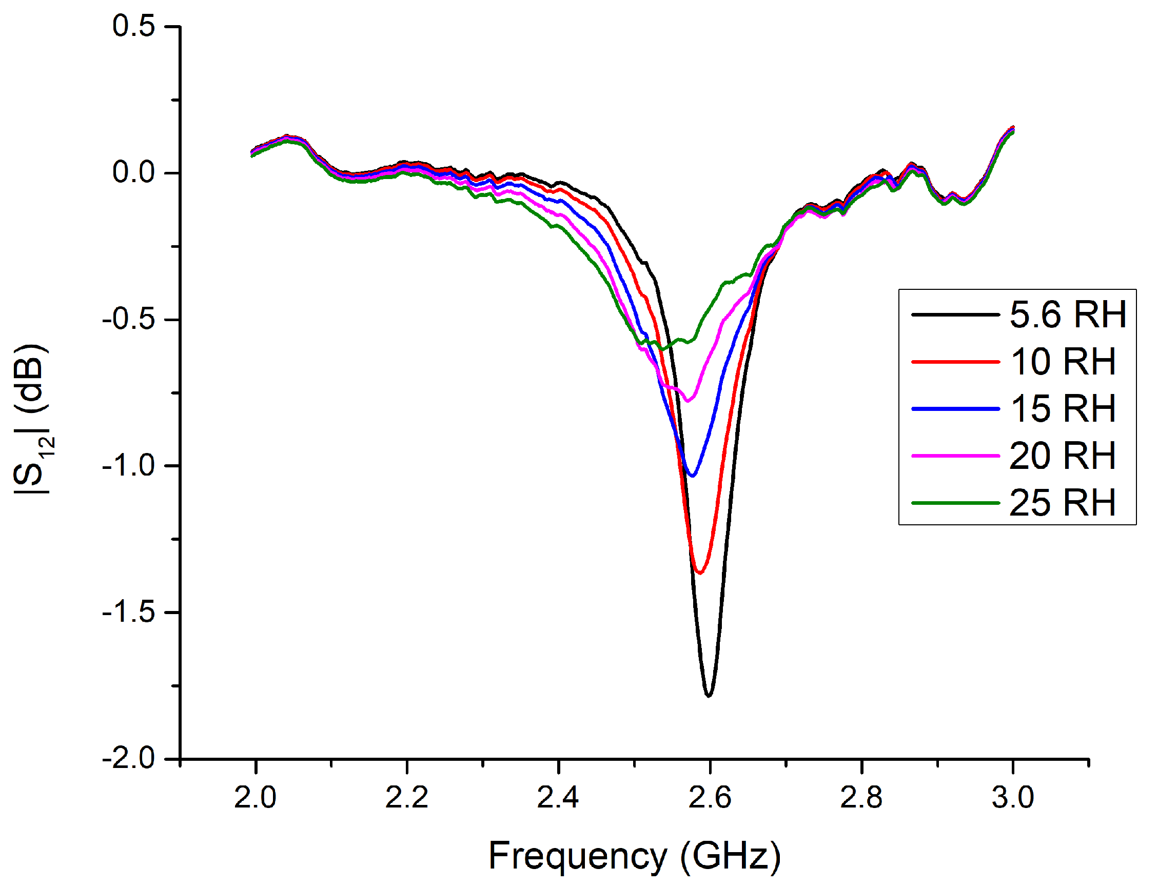
Figure 4 plots the variation of the first resonance peak for RH up to 25%. We decided to report only the acquisitions up to RH 25% since the sensor is designed to work well at low-humidity but is less performing at higher humidity due to the broadening of the resonance peak. The discrepancies in terms of the frequency range of the peaks that can be noticed comparing simulation and measurement results are known and well explained in [
16]. They are due to the dielectric values of Nafion 117 used in the simulation process which were not specifically studied for the use case of Nafion 117 in chipless sensors. Nevertheless, they result to be a good guiding line to verify the electromagnetic behavior of Nafion 117 as a sensitive layer for chipless sensors. A more precise correspondence could be found by reversely characterizing its dielectric values from chipless sensitive tests.
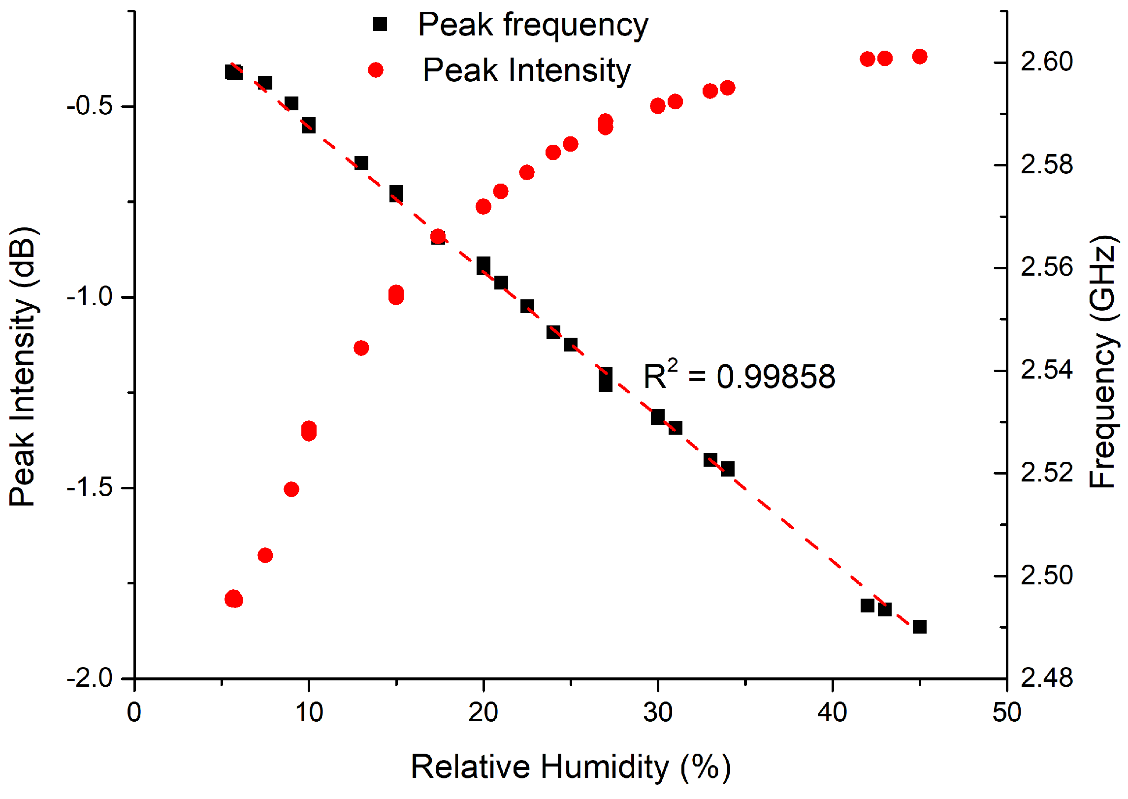
Figure 5 shows that as humidity increases the sensor prototype presents a linear shift of the resonance peak toward lower frequencies, while the variation of the peak intensity is not linear. As a consequence, it could be strategic to monitor its frequency shift in order to take advantage of this linearity.
Considering the frequency shift, we can quantify the sensitivity improvement obtained within the sensor prototype on DiClad if compared with that on RO4003 proposed in [
16]. We will consider for this comparison data related to RH 10% and 20% since both studies include these humidity values. We discover that our theory is experimentally well supported and verified since the sensor on RO4003 has a sensitivity of 11.2 MHz/RH%, while the sensor on DiClad is characterized by a more than doubled sensitivity of 27.17 MHz/RH%. In general, thus, given the nature of chipless tags, it is recommended to look for mechanisms to enhance their discrimination capability. With this work we have demonstrated that in the case of chipless sensors exploiting as detection mechanism the linear frequency shift the sensitivity can be appropriately tailored by choosing the most suitable substrate for the selected sensitive layer.
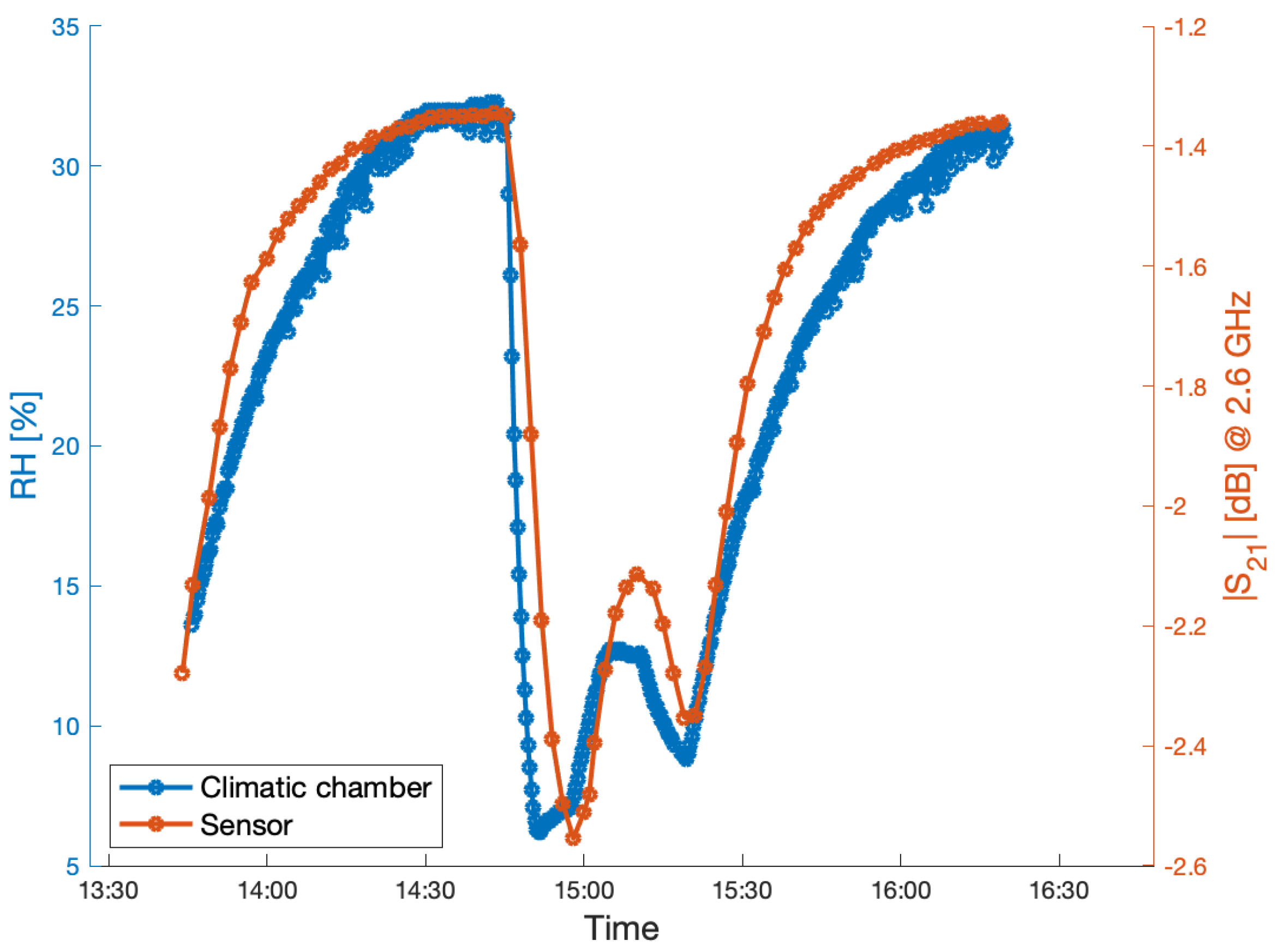
Finally, in
Figure 6 we presented some results of the experiments made to test the sensor in its repeatability and ability of real-time sensing properties. We repeated some 10–30% RH transactions. The sensor proves to follow well the climatic chamber behavior and the sensor response and recovery times are only limited by the climatic chamber transaction times.


 ,
, 


