Article

A Power-Efficient Neuromorphic Digital Implementation of Neural–Glial Interactions †

by
Angeliki Bicaku
,
Maria Sapounaki
,
Athanasios Kakarountas
* and
Sotiris K. Tasoulis
Computer Science and Biomedical Informatics, University of Thessaly, 35131 Lamia, Greece
*
Author to whom correspondence should be addressed.
This paper is an extended version of our paper published in the 28th IEEE International Conference on Electronics, Circuits, and Systems (ICECS). Bicaku, A.; Sapounaki, M.; Kakarountas, A. A low-complexity bit-efficient Neuromorphic Astrocyte-Neuron Circuit, In: 2021 28th IEEE International Conference on Electronics, Circuits, and Systems (ICECS). IEEE, 2021; pp. 1–6, doi:10.1109/ICECS53924.2021.9665537.
J. Low Power Electron. Appl. 2023, 13(1), 10; https://doi.org/10.3390/jlpea13010010
Submission received: 16 November 2022 / Revised: 15 January 2023 / Accepted: 16 January 2023 / Published: 18 January 2023

Abstract

:
Throughout the last decades, neuromorphic circuits have incited the interest of scientists, as they are potentially a powerful tool for the treatment of neurological diseases. To this end, it is essential to consider the biological principles of the CNS and develop the appropriate area- and power-efficient circuits. Motivated by studies that outline the indispensable role of astrocytes in the dynamic regulation of synaptic transmission and their active contribution to neural information processing in the CNS, in this work we propose a digital implementation of neuron–astrocyte bidirectional interactions. In order to describe the neuronal dynamics and the astrocytes’ calcium dynamics, a modified version of the original Izhikevich neuron model was combined with a linear approximation of the Postnov functional neural–glial interaction model. For the implementation of the neural–glial computation core, only three pipeline stages and a 10.10 fixed point representation were utilized. Regarding the results obtained from the FPGA implementation and the comparisons to other works, the proposed neural–glial circuit reported significant savings in area requirements (from 22.53% up to 164.20%) along with considerable savings in total power consumption of 28.07% without sacrificing output computation accuracy. Finally, an RMSE analysis was conducted, confirming that this particular implementation produces more accurate results compared to previous studies.

1. Introduction

Over the past few decades, neuroscience researchers have been trying to explicitly investigate the fundamental function of the primary blocks of the central nervous system (CNS), that is, the neurons, in order to comprehend the brain’s information processing mechanism. However, accumulating computational and experimental evidence indicates that neural cells are not the only pivotal and active elements responsible for axonal conduction, synaptic transmission, and neuronal information processing. Specifically, the most abundant type of glial cells in the CNS, astrocytes, were previously believed to exist only for sustenance and protection reasons. However, it has been suggested that they actually have the capability to contribute actively to the formation, protection, and orchestration of neuronal–synaptic communication, which includes neuronal depolarization or hyperpolarization affecting neighboring neurons. Their contribution is conducted by a process called gliotransmission. Therefore, it is becoming clear that if the neuronal activity is to be thoroughly and accurately modeled, a prerequisite is that the neurons, astrocytes, and synapses each need to be considered.
Accordingly, the first component that should be investigated and modeled in order to shed light on neuron–astrocyte crosstalk is the neuron. Neurons are extremely specialized cells with distinctive morphology and functionality. They consist of the dendrites, which receive the signals coming either from the outer environment or other neurons, the soma, which gathers and processes these signals, and the axons. If the signals are strong enough and surpass a predefined threshold, an action potential is generated. This threshold concerns the charge of neuronal membrane potential; therefore, an action potential is a rapid change in the polarity of the membrane. This polarity shift occurs due to the flux of ions between the extra- and intra-cellular environments via ionic channels. Consequently, N a 2 + from the outer environment flows into the cell, turning its polarity positive, while K + efflux deprives the cell of its positive charges.
Typically, the intensity of the membrane voltage fluctuates from −70 mV to +30 mV [1]. The lower limit is known as the resting potential, because at that point the neuron is inactive, while the upper limit represents the end point of N a 2 + influx and the beginning of K + efflux [2]. The final component of the neural cell, the axon, propagates this action potential to the axon terminal and thence to the dendrites of the next neuron, namely, the post-synaptic neuron. At the synaptic cleft, the exact site at which the pre- and postsynaptic neuron are connected, the released neurotransmitters produced by the presynaptic neuron bind to the receptors of the postsynaptic neuron, and in this way signal transmission is achieved.
The next component that needs to be examined in order to develop a biologically-inspired model and to clarify glial-dependent regulation of neural activities is the astrocyte. In the human frontal cortex, the ratio of astroglia to neurons is approximately 1:1; however, this ratio varies from area to region [3]. Looking closely at the star-shaped glial cells themselves, it should be noted that these non-neuronal cells regulating neuronal activity play an indispensable role in ensheathing neuronal synapses, leading to the formation of the so-called tripartite synapse. Therefore, neuron–synapse communication is reinforced by the intervention of astrocytes. Even though the latter are not capable of producing action potentials, their contribution in this tripartite structure is measured by the fluctuations of intercellular and intracellular C a 2 + levels [4]. Their main functionality includes the release and modulation of neurotransmitters and activating factors along with the dissociation of surplus neurotransmitters.
The bidirectional communication between neurons and astrocytes is accomplished by signaling pathways generated by the release of neurotransmitters from neurons, which then bind to the receptors of the astrocytes [5]. In this way, astrocytes create bidirectional communication pathways between both pre- and postsynaptic neurons, offering them the requested feedback and thereby regulating neuronal behavior. Additionally, interconnections in astrocytic networks are prominent; in these interconnections astrocytes are connected by gap junctions, which act as channels to facilitate the exchange of nutrients and ions between astrocytes, forming a large functional syncytium.
Neuromorphic computer systems are envisioned as the center of next-generation “neuro–bio hybrid” systems, in order to create devices that are both energy-efficient and capable of real-time exploitation for the treatment of neurological problems. Considering the significance of the aforementioned biological components for the nervous system, many neuroscientists have endeavored to model this tripartite connection in the battle against neurological diseases. In particular, researchers have been attempting to approach this problem from biological, physiological, and engineering perspectives in order to acquire full and accurate comprehension of the brain’s functionality. Towards this goal, a plethora of research works has been presented implementing various neuronal and glial models. In particular, neuromorphic engineers have employed various hardware platforms and software techniques in order to implement the existing mathematical descriptions of these biological structures.
Analog VLSI platforms were the first large category used in the implementation of dynamic models of neurons. Taking advantage of the characteristics that analog technology offers, such as accuracy and efficiency, scientists have proposed numerous implementations. Haghiri et al. presented a VLSI implementation modeling dynamic neural–glial behavior [6]. Another analog implementation was suggested by Azad et al. in 2018, emphasizing retrograde signaling by simply leveraging the existing features of neural–glial interactions [7]. Moreover, Tir et al. proposed an analog integrated circuit for modeling the tripartite synapse with 65-nm CMOS technology [8]. However, all of these platforms are interwoven with inflexible and time-demanding procedures. The employment of digital approaches seems to overcome these constraints. The benefit of digital designs lies in their ability to achieve faster computation and better stability while being more robust with respect to signal noise. However, digital implementations tend to consume higher amount of power and silicon area compared to analog ones used for the same task.
For the design of precise, widely available, low cost, and flexible neuromorphic digital systems, FPGAs and ASICs are proving to be a promising substitute for analog VLSI-based implementations. Because ASICs are designed for a specific purpose, they can outperform other platforms in terms of silicon area, power consumption, and computational speed. Nevertheless, ASIC board development requires high prototyping cost and a longer time-to-market due to the more complex design flows involved (including place and route, DRC check, etc.). Additionally, ASIC technology presents limited access to the scientific community, mainly due to cost and access to foundries, making fair comparisons among ASIC implementations unattainable at to date. On the contrary, FPGA platforms are more suitable for the assessment of different proof of concepts. Thus, most similar works report characterization in terms of area requirements and performance only for FPGA devices, making it easier for different research approaches to be compared.
Moreover, these devices present efficient performance in terms of time, even when complex calculations need to be conducted, thanks to their parallel structures. Furthermore, they are characterized by reconfigurability and a high density of logic gates, both attributes that offer great flexibility. The aforementioned features, along with their low development costs, make FPGA boards ideal candidates for fast prototyping.
Bearing the above in mind, many studies have been reported in the literature exploiting FPGA platforms to implement neuron–astrocyte cross-talk in hardware. These studies either focus on a single neuron, an astrocyte, and their interactions, or study a complete neuron–astrocyte network.
One excellent illustration is the work conducted by Nazari et al., in which a multiplier-free implementation is used to mimic a simplified loop interaction between a neuron and a glion [9]. This study is one of the reference designs that we use in our study. Furthermore, in 2016 Hangiri et al. introduced a novel full tripartite synapse model that has the ability to emulate the complete IZH neuron and astrocyte inter-linkage, and in addition can be easily implemented digitally [10]. Another noteworthy implementation that aims to accentuate the role of the astrocyte in modulating neurons’ spiking activity was presented by Hangiri and colleagues in 2021. In that particular implementation, the neuron model they chose for testing with the astrocyte effect in a tripartite synapse was the Hodgkin–Huxley (HH) model, which is able to reproduce the most biologically plausible neuronal behaviours among all the existing mathematical neuron models [6].
Additionally, a hardware approach that can be utilized in self-repairing neural networks and spike-based learning mechanisms is presented in [11]. This approach demonstrates the neural information encoding mechanism through calcium oscillations. Moreover, a pre-synaptic neuron, the synaptic terminal, a post-synaptic neuron, and an astrocyte cell that acts as a controller module to the neurons’ spiking frequency are all included in the VHDL–AMS-based tripartite synapse model, and are demonstrated in [12]. In one of our own previous studies [13], we presented a bit-efficient digital astrocyte–neuron circuit with low computational cost that implemented a linear approximation of the astrocytes’ calcium dynamics along with a modified version of the Izhikevich neuron model provided by [14] and [15]. The present work is to an extension of the work we conducted in [13], aiming to achieve lower computational cost, silicon area, and power consumption.
In the present work, a power-efficient and computationally low-cost hardware implementation is presented, with the aim of shedding light on astrocyte-dependent regulation of neural activities. In the proposed astrocyte–neuron circuit, a linear approximation of the original Postov model is employed to represent the astrocytes’ calcium dynamics and the synaptic connection between the neuron and the glial cell. On the other hand, the neuronal behaviour is described by a modified version of the original Izhikevich model proposed by Cassidy et al. [14]. This digital framework, which intends to emulate biological bidirectional neural–glial signaling, is implemented in an FPGA platform and described using VHDL.
The rest of this work is organized as follows. Section 2 offers a thorough mathematical background of the existing computational models for both neurons and astrocytes, along with their bidirectional communication, and outlines the models utilized in this work. Section 3 provides a brief description of the proposed architecture for a power- and time-optimized neuron–astrocyte circuit and reports a comparison between our proposal and reference designs. In Section 4, the results obtained from the software simulations and hardware analysis are demonstrated and an RMSE analysis is conducted based on the different implementations. An analysis regarding the corresponding results is provided in Section 5. Finally, in Section 6 we present our concluding remarks and discuss the future directions of this research.

2. Dynamic Neuron and Astrocyte Models

In the following section, the fundamental compartments of the tripartite synapse are thoroughly presented. First, the mathematical background fundamentals of the Izhikevich neuron model are described, and subsequently, the astrocyte and synapse models are provided.

2.1. Neuron Model

Beginning in the 1940s, when the first mathematical description of a neuron was introduced by W. McCulloch and W. Pitts [16], an enormous number of mathematical neuron models and their modifications have been proposed. For instance, the Huxley and Hodgkin (HH) neuron model is thought to be the most accurate in terms of biological resemblance, yet it is the most complex and power consuming. On the other hand, Morris–Lecar is a reduced version of the HH model engaging one K + and one non-activated N a 2 + current [17], both being close to biological plausibility. Moreover, biologically inspired and at the same time simplified models, such as the family of Integrate and Fire (I&F) models, have been suggested, as has the Izhikevich model (IZH) [18]. In recent years, the IZH model has become one of the most preferred models for neuromorphic digital implementations, as it is capable of producing tonic spiking and bursting dynamical behaviours with a considerable biological resemblance and succeeds in keeping the computational complexity relatively low. Furthermore, it is capable of reproducing a wide variety of spiking and bursting behaviours seen in well-known types of cortical neurons [19]. These advantages have made the IZH model preferred among scientists. Thus, numerous research works have either implemented the original [20,21] equations of the IZH model or proposed modifications [15,22,23,24,25] with the goal of achieving better performance and/or lower complexity of the calculations. The IZH model is composed of a two-dimensional system of Ordinary Differential Equations (2D ODE) (1) and (2), four dimensionless parameters, and an auxiliary after-spike resetting condition (3), as follows:
v = 0.04 v 2 + 5 v + 140 u + I
u = a ( b v u ) ,
with the auxiliary after-spike resetting expressed as
i f v 30 mV , t h e n v c u u + d
where v and u depict the membrane potential and the membrane recovery variable of the neuron, respectively. Variable a indicates the time scale of variable u, and consequently, its decrease is correlated with slower recovery, while b represents the sensitivity of the recovery variable to the sub-threshold variations of v values. Parameters c and d are engaged if the after-spike condition is satisfied. In this case, c is assigned to variable v, representing the fast high-threshold K + conductances, and d is assigned to the recovery variable u, indicating the slow high-threshold N a 2 + and K + conductances.
In this work, a modified version of the original IZH model is employed. The modification was obtained from the work conducted by A. Cassidy et al. [26], which suggests the multiplication of the terms in Equation (1) and Equation (2) by a weight of 0.78125 . This modification is recommended in order to facilitate the digital implementation of the model, as in this manner the terms of the equations can be represented as powers of two by considering the convention that 3.91 ≈ 4. The modified equations are as follows:
v = 1 32 v 2 + 4 v + 109.375 u + I
u = a ( b v u ) .

2.2. Astrocyte Model

After realizing the importance of astrocytes, scientists have tried to generate mathematical models in order to emulate their behavior in the tripartite synapse. A relatively high number of mathematical models, characterized by different levels of complexity and biological plausibility, have been proposed [27,28,29,30,31]. Among the most prevalent is the one introduced by Postnov et al. [32], which models the behavior of the astrocytic calcium dynamics mathematically with high biological similarity; it is described by the following equations:
τ c d c d t = r + α w 2 w 2 * + β S m c c 4 f c , c c + D a ξ ( t ) ,
ε c τ c d c e d t = f c , c e
f c , c e = c 1 c 2 1 + c 2 c e 2 1 + c e 2 c 4 c 2 4 + c 4 c 3 c e
In Equation (6), c represents the C a 2 + concentration in the cytoplasm of the glial cell, while c e is the C a 2 + concentration in the internal store of the astrocyte which corresponds to the endoplasmic reticulum (ER). The term ( r + α ( w 2 w 2 * ) + β S m ) is the C a 2 + influx from the extracellular space into the astrocyte’s cytoplasm. In particular, the parameter (r) denotes a constant transmembrane current which controls the initial state of calcium oscillation, while the next term of Equation (6), ( α ( w 2 w 2 * ) ), implies the potential-dependent calcium current that enters the astrocyte, which is activated by the cells’ depolarization resulting from the increase in the extracellular concentration of potassium ions. This procedure is actually the potassium ( K + ) activation pathway or fast activation pathway. The parameter α controls the strength of this pathway. The variables w 2 and w 2 * respectively represent the recovery variable and the reference level of the post-synaptic neuron when in its resting state.
The term D a ξ ( t ) represents the noise due to environmental variations. The term β S m indicates the activation of the slow pathway, known as the I P 3 pathway, which corresponds to the activation of the glial cell after the synapse has been triggered by the firing of the pre-synaptic neuron and the neurotransmitter glutamate has been released into the synaptic cleft.
Afterwards, the glutamate is able to reach the metabotropic glutamate receptors (mGluR) on the adjacent astrocyte’s membrane. The astrocyte reacts to this stimulus with several biochemical events and especially, producing I P 3 ( S m variable) and releasing it into the astrocyte’s cytoplasm, which subsequently binds to the I P 3 R s on the ER. This event leads to the opening of the channels that enable the release of C a 2 + from the ER to the cytoplasm, consequently inducing calcium oscillations. Moreover, the parameter β implies the strength of the slow activation pathway. In Equations (6)–(8), the term f ( c , c e ) indicates the association between the C a 2 + oscillations evoked in the cytoplasm and in the ER [33]. The generation of I P 3 that is evoked by the synaptic activity is described by Equation (9):
τ S m d S m d t = 1 + tan h S S m z h S m × 1 S m S m d S m .
The intra-astrocytic free calcium concentration provokes the propagation of glutamate, known as a glion mediator ( G m ), described by Equation (10), and/or the release and hydrolysis of ATP ( G a ), described by Equation (11), into the intracellular space. The aforementioned process is known as gliotransmission [34,35]. Then, the glutamate molecules adhere to NMDA-Rs on the post-synaptic neuron and/or to mGluRs on the membrane of the pre-synaptic neuron. Consequently, the variable G m regulates the pre-synaptic transmission, and thus the synaptic current, and simultaneously controls the possibility of post-synaptic excitability.
τ G m d G m d t = 1 + tan h S G m c h G m × 1 G m G m d G m
τ G a d G a d t = 1 + tanh s G a c h G a 1 G a G a d G a
The above equations additionally comprise a number of threshold parameters, including h S m , h G m , and h G a , which are used to differentiate the activation and inactivation states of the variables Z and c. Additionally, d S m , d G m , and d G a tune the deactivation rhythms and the parameters τ c , τ S m , τ G m , and τ G a are responsible for regulating the time scales.
By alternating the coupling coefficients between the neurons and the glial cell within the tripartite synapse, which are represented by α , β , γ , δ , and η , various dynamic behaviours of distinct pathways can be engendered. The two primary routes (the fast and slow pathways) of glial activation and the corresponding responses are shown in Figure 1 along with a functional diagram of the sub-units and the relevant model variables. It is clear from the figure that the pre- and postsynaptic neurons present oscillatory behaviour. On the other hand, the astrocyte mediator productions and the synapse are posed with threshold activation components.
In research work conducted by Nazari et al. [9], the nonlinear equations presented above were substituted with their linear approximations to achieve low cost hardware implementation on digital platforms while retaining the original model’s efficiency.
For the same reasons, in our study, we have opted for this simplified astrocyte dynamical model, which is able to define the most substantial pathways of neural–glial bidirectional signaling and enable good comprehension of both the primary forms of astrocytic response to neuronal activity and the consequent dynamical patterns. The piecewise-linear model for astrocyte calcium dynamics is composed of Equations (12)–(14):
d c d t = 0.5 c + 0.5 s m + 0.01
d s m d t = 0.0937 Z 1.25 s m 0.0015
d G m d t = 10 c 0.25 G m + 0.035

2.3. Model of Astrocyte–Neuron Interaction

Because they play a pivotal role in axonal conduction, synaptic transmission, and information processing, astrocyte–neuron interactions are a prerequisite for the normal operation of the central nervous system. In 2004, Nadkarni and Jung first suggested the idea of the “dressed neuron” [36]. Specifically, the star-shaped glial cells have the potential to control synaptic transmission by uptaking neurotransmitters such as ATP, GABA, and glutamate from the synaptic cleft, as well as by releasing chemical transmitters to the synaptic cleft after a sequence of biochemical events has taken place within their cytoplasm. These events were described briefly in the previous section.
According to the functional model presented in [32], the variable Z defined by Equation (15) corresponds to the synaptic activation variable:
τ s d Z d t = 1 + tanh S s v h s ( 1 Z ) Z d s .
The parameters included in Equation (15) are defined as follows:
  • τ s : Time delay (s)
  • S s , d s : Factors responsible for the activation and relaxation of parameter Z
  • h s : Threshold parameter for activation of Z
  • v: membrane potential of the pre-synaptic neuron.
When the pre-synaptic neuron triggers the synapse due to the threshold parameter h s being greater than the neuron’s membrane potential, the synapse is not activated; thus, Z = 0 . When the value of v increases, the hyperbolic tangent function changes at a rate of 1/ τ s, in which case Z = 1 .
Notwithstanding this, with the aim of achieving a low-complexity digital implementation we decided to use a simplified equation to model the synaptic interactions, as first suggested by [27]:
[ T ] = 1 1 + exp v ( t ) θ s / σ s .
Therefore, in Equation (16) the variable [ T ] indicates the concentration of neurotransmitters in the synaptic cleft, which is determined based on the value of the membrane potential v, while θ s and σ s correspond to the half-activation voltage and the steepness of the sigmoid function, respectively. Additionally, the synaptic variable Z, which defines the astrocyte input and simultaneous inducement of ( I P 3 ) production, is modeled by Equation (17), obtained from [37]:
Z = λ [ T ] .
Here, the parameter ( λ ) indicates an amplifying parameter representing the feed-forward strength from the neuron to the astrocyte, which should be greater than zero. It can be assumed that the concentration of neurotransmitters liberated in the synaptic cleft controls production of the secondary messenger, inositol 1,4,5-triphosphate ( I P 3 ). The production of I P 3 molecules leads to a sequence of biochemical processes within the glion, which are subsumed in a process called gliotransmission. One important byproduct of this process is the astrocyte mediator (glutamate), which reaches the synaptic terminal and provides feedback to the neuron, thereby contributing to synaptic transmission. Consequently, the astrocyte’s output is defined as follows:
i a s t r = γ G m
where the parameter γ represents the feedback strength from the astrocyte to the neuron. By integrating the astrocyte’s feedback mechanism, the full expression of the neuron’s input current is defined by the following equation (19):
I i n p u t = I + i a s t r
where i a s t r is the feedback current from the astrocyte and the variable I is the synaptic input current of the neuron. The astrocyte and neuron information exchange loop analysed below is depicted in Figure 2.

3. Materials and Methods

It is noteworthy that systems emulating the procedure of information processing which occurs in the human brain are astonishingly effective for computing applications. Despite the enormous resources invested in researching and developing computing, information, and communication technologies, biological systems continue to outperform even the fastest and largest computers in terms of robustly completing tasks in the real world.
In this particular section, the hardware realization for a digital neuron–astrocyte circuit is briefly described. The proposed architecture of the neural–glial computation core consists of a modified IZH neuron, as introduced by Cassidy et al. [14], synaptically connected to the modified astrocyte model proposed by Nazari et al. [9].
Discretizing the equations is the first step required for the digital implementation of continuous time dynamical equations. This is achieved by employing the Euler method. The following are the resulting equations describing the v and u dynamics of the IZH neuron, considering the glial influence and incorporating the astrocytes’ output to the neurons’ input current.
v [ n + 1 ] = ( 1 32 v 2 [ n ] + 4 v [ n ] + 109.375 u [ n ] + I i n p u t [ n ] ) h + v [ n ]
u [ n + 1 ] = ( b v [ n ] u [ n ] ) h a + u [ n ]
Likewise, the astrocyte model’s dynamic equations are discretized as follows:
c [ n + 1 ] = ( 0.5 c [ n ] + 0.01 + 0.5 S m [ n ] ) h + c [ n ]
S m [ n + 1 ] = ( 0.0937 Z [ n ] 0.0015 1.25 S m [ n ] ) h + S m [ n ]
G m [ n + 1 ] = ( 10 c [ n ] + 0.035 0.25 G m [ n ] ) h + G m [ n ]
In the equations above, h stands for the discretizing step, which in our design is set to 1 ms.
Additionally, regarding the hardware implementation of the synapse component, Equation (16), which models the concentration of neurotransmitters in the synaptic cleft, is simplified through a linear approximation, as suggested in [9]. As such, if
v 0   m V , [ T ] = 1 Z = λ
In any other condition, [ T ] = 0 ; hence, Z = 0 .
The architecture for the neuron–astrocyte interaction model suggested in this research work is illustrated in Figure 3 using arithmetical trees. The parallelism in time through pipelining is escalated by these trees. Each tree has a full pipeline of calculations to facilitate full rate data-flow processing. This architecture comprises an IZH neuron circuit, which is depicted at the bottom of Figure 3. The neuron’s discretized Equations (20) and (21) are implemented using two parallel arithmetic pipelines in order to obtain the membrane potential and recovery variable in one iteration. Similarly, the discretized dynamical equations of the astrocyte, (22)–(24), are implemented as shown in the upper part of Figure 3.
Moreover, in this specific design, the output is generated in the final cycle of each iteration employing a sequential technique. Using the previously produced samples, the whole technique is conducted in order to produce each output sample. This digital implementation includes simple operators, namely, multipliers, adders, adder/subtractors, right and left shifters, multiplexers, and comparators.
In this study, we attempt to make use of fewer multipliers than in the previously proposed architecture by Bicaku et al. [13], as multipliers are expensive blocks in terms of space and power usage. This is achieved by implementing the multiplication of parameter a in Equation (20) with a right shift by six bits. As a result, the hardware implementation cost is drastically decreased.
The total quantity of each operator used in this research work, in contrast to the number of operators utilized in [9,13], is demonstrated in Table 1. From Table 1, it can be determined that this work generally uses fewer operators than [9,13]. However, in [9] no multipliers are utilized, as a linear approximation is applied for the neuron dynamics, which in fact produces less biologically precise results. Furthermore, the three input currents I s t a t , I i n h , and I e x c represented in the architecture in [13] are not incorporated in our proposed design, as it was observed that these signals add complexity to the overall system. When excluding them, the accuracy and biological plausibility of the resulting signals remain unchanged. In contrast to the architectures presented in [9,13], where no reports are provided for the synapse implementation, in this design the synapse part is implemented using a comparator and a multiplexer.
Furthermore, the proposed design is optimized in terms of speed and area, as three pipeline stages are used in order to obtain the final outputs for the neuron and the astrocyte circuit. From Figure 3, it is evident that the two subcircuits work in parallel. Additionally, in this particular implementation, both the hardware resources and the latency are decreased, while the throughput and the frequency of our architecture are maintained at the same level. On the other hand, the architectures of the neural–glial computation core suggested in [9,13] require at least six and eight pipeline stages, respectively, in order to calculate the output signals.
Additionally, each block output uses a memory register. The output signals to be utilized in the subsequent computations are stored in those registers. Depending on the kind of application, computational speed, resource utilization, and accuracy needed for realization, individual state variables are stored in n-bit registers.
Accordingly, another important step considered in this implementation was the determination of the bit width for the different variables and parameters. Compared to floating-point engines, fixed-point computing units are often faster, and use fewer hardware resources and power. Taking into consideration the aforementioned assumption, in this work, we used a 10.10 fixed point representation. This twenty-bit representation was used to aid comparison with the design reported in [9]. However, the bit width used for the integer and the fractional part is significantly different from that reported in [9].
Specifically, the fixed-point representation in this study comprises one bit for the sign, nine bits for the integer portion, and ten bits for the fractional portion. The two key factors taken into account in order to determine the bit width while simultaneously avoiding any overflow and achieving the maximum precision were the maximum span of the shift operations and the ranges of the parameters and variables. In this structure, the maximum span of shift operations corresponds to a six-bit right shift. Furthermore, the variable that requires the largest proportion of bits in the integer part in order to be accurately represented is v, which corresponds to the tonic neuron’s membrane potential and presents a range approximately from −75 mV to 30 mV. These values require at least eight bits in the integer part. On the other hand, the smallest parameter in the model has a value of 0.0015 and requires ten bits in the fractional part in order to be approximately represented.
Compared to the reference designs, first, in [13] a 16.16 fixed-point representation was used, which while slightly more accurate is obviously a larger word length than the representation used in this work. On the contrary, Nazari et al. [9] used a 4.16 representation, which fails to accurately represent the variables, as the four-bit integer part fails to represent variables with high values; for instance, the neuron’s membrane potential requires an integer part of at least eight bits.

4. Results

In the subsequent section, the results of software simulations and hardware implementation of the neuron–astrocyte interaction model are provided. It is important to stress that the neural–glial model parameters used in the hardware and software implementations are reported in Table 2 and Table 3, respectively.

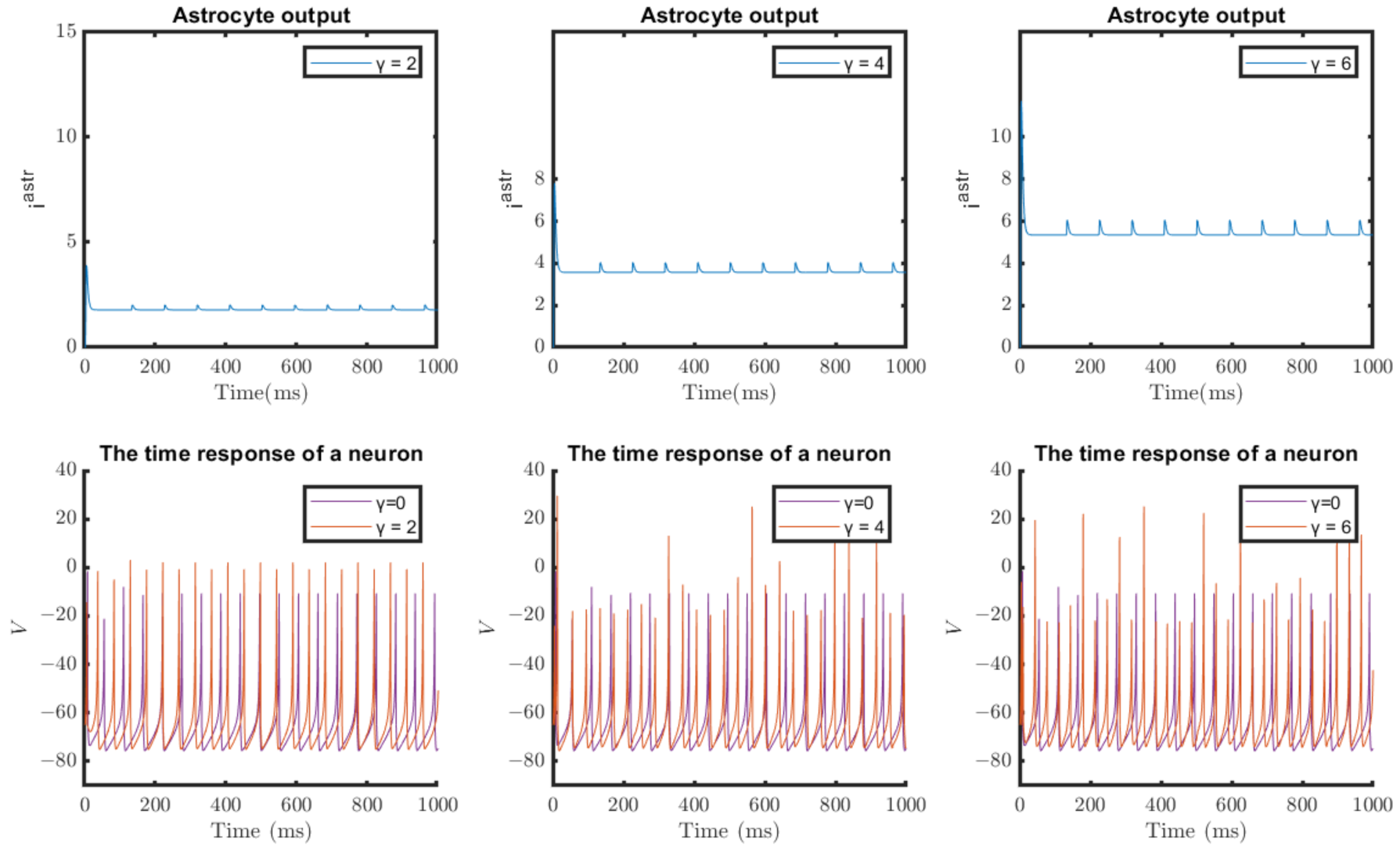
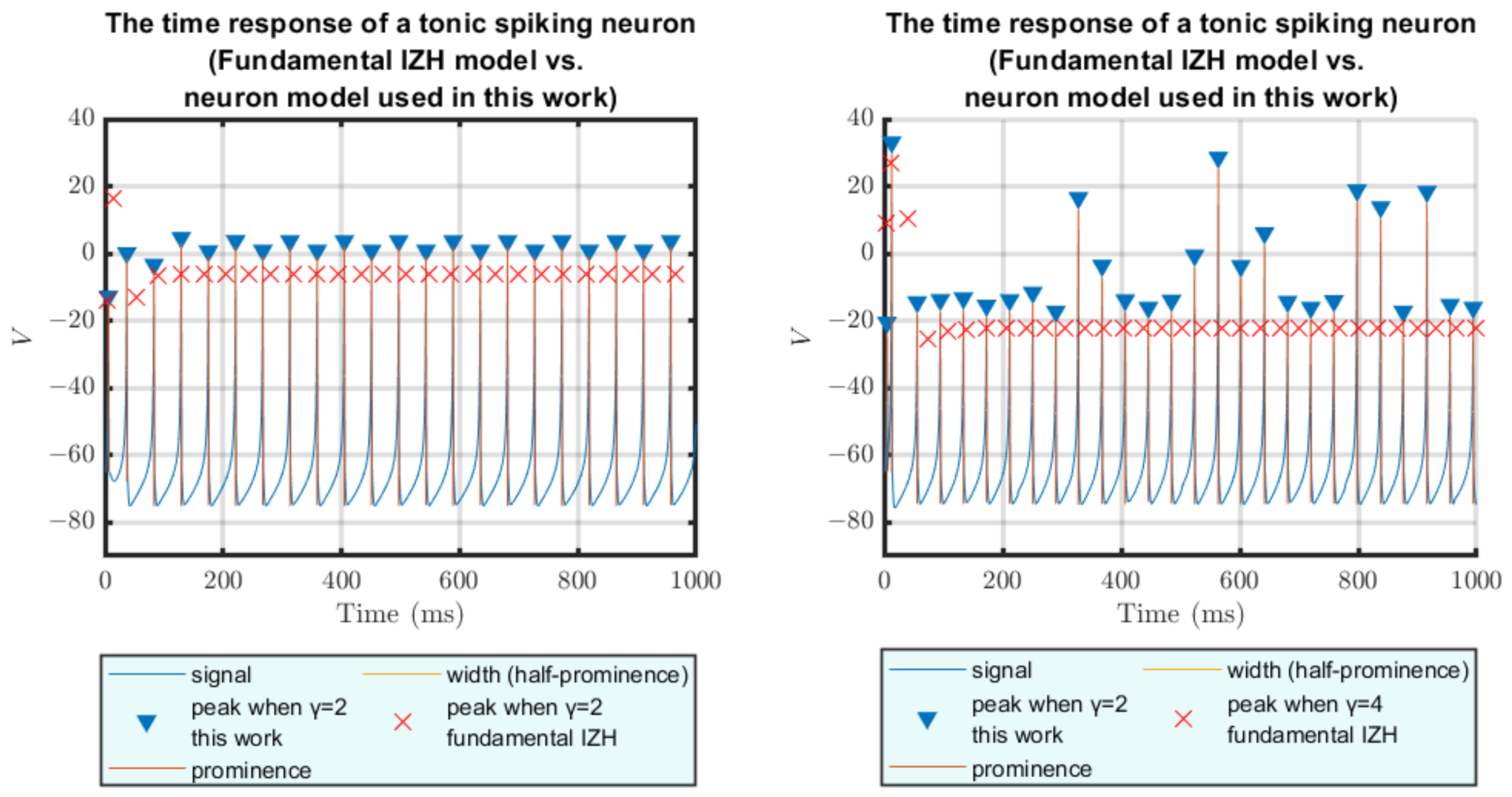
4.1. Results of Software Simulations

Intending to observe the role of astrocytes in regulating synaptic activity and modulating neuronal firing patterns, several experiments were conducted using the MATLAB environment. First, the neuron–astrocyte interaction model used in this work was simulated in an effort to test its ability to accurately emulate the dynamic behaviour of its biological counterpart. Hence, the experiments demonstrated in Figure 4, Figure 5, Figure 6 and Figure 7 aimed to evaluate both spiking and bursting activities in order to consider a wide range of dynamic neuronal behaviors. The set of parameters used for the neuron models is provided in Table 2. In addition, when the tripartite synapse was modeled, various astrocytic parameters were carefully selected in order to explore how neuronal behaviour is attuned. The parameters used for the astrocyte dynamic model are listed in Table 3.
Specifically, the first behaviour that was tested was the tonic spiking behaviour of a neuron; the results are presented in Figure 4. The bottom panel includes the response of the tonic neuron in time (1000 ms). The purple color implies that the astrocyte does not apply a feedback mechanism to regulate neuronal excitability; consequently, the astrocyte feedback strength γ = 0. By considering the astrocyte’s effect on the neuron and the synapse, thereby simulating a more biologically realistic situation, the dynamic behaviour (orange) can be seen, which indicates the neuron’s response when astrocytic feedback strength is applied. The feedback strength γ was set to 2, 4, and 6 in order to observe the effect of its variation. The astrocyte’s output current when the γ parameter was set to 2, 4, and 6, is represented by the blue colour in the upper panel of Figure 4.
An identical experiment is depicted in Figure 5, except that this time the tonic neuron presents dynamic bursting behaviour. It is more than evident when by taking into account the closed-loop astrocyte feedback in the simulation, the overall rate of spike or burst generation is significantly magnified by increasing the astrocyte feedback strength ( γ ).
In the two aforementioned experiments, when the astrocyte feedback strength is applied, the feed-forward strength from the neuron to astrocyte λ is adjusted to 0.5. Aiming to provide a better understanding of the effect of the astrocyte on the neuron firing frequency, the parameter λ was changed from 0.5 to 0.9. Similar experiments to those shown in Figure 4 and Figure 5 were conducted for spiking and bursting behaviour, this time with λ = 0.9; the results are shown in Figure 6 and Figure 7. It can be seen that increasing the λ parameter alters the neuron’s excitability, as its firing frequency is magnified.
Therefore, it is essential to consider both the feed-forward strength from the neuron to the astrocyte ( λ ) and the astrocyte’s feedback strength ( γ ) when examining the manner in which an astrocyte alters neuronal excitability.
A critical aspect of information processing in the brain is the neuron’s firing pattern, which comprises both the frequency and timing of action potentials. The exact timing of action potentials is crucial for the “temporal code”, whereas the “rate code” represents information by regulating the firing rate. Considering the results outlined above, it is evident that the astrocyte is capable of modulating neural excitability; as such, variations in the feedback and feed-forward strength should be considered a vital mechanism for information encoding, as they promote an assortment of neural responses.
An additional set of experiments was conducted in order to compare the time response of the tonic spiking neuron used in this work, the neuron model suggested in [9], and the original IZH neuron model [18], considering the astrocyte effect in all the cases except for the experiment illustrated in Figure 8. This particular experiment shows the peaks of the membrane potential signal (v) produced by the dynamic neural model used in this work when feedback strength ( γ ) is applied or not. It is distinguishable that the amplitude of the membrane potential signal is increased when γ = 2, in contrast to the amplitude of the spikes when the astrocyte influence is not taken into account. When γ = 4 the amplitude presents an unexpected behaviour, with a portion of the peaks being above the peaks that occur when the neuron behaviour is examined without the glion effect, and the remaining portion of the peaks being below this level.
In the experiment presented in Figure 9, the neuron model used in this study is compared to the original IZH neuron model [18] considering the astrocyte effect and adjusting γ to values of 4 and 2. In this case, it is noticeable that regardless of the value of γ the amplitude of the membrane potential signal of the original IZH neuron response is much lower than the neuron response reported in this work.
In Figure 10, it can be seen that the amplitude of the membrane potential signal produced by the neuron used in this study is increased when γ is either 2 or 4, in contrast to the amplitude of the spikes generated by the neuron model reported in [9].
Table 4 summarizes the overall number of spikes within 1000 ms for the neural–glial model used in this work when γ is set to 0, 2, and 4, compared to the neural–glial model used in [9] and the neural–glial model utilizing the original IZH neuron model [18] when γ is set to 2 and 4. Specifically, from Table 4 it can be seen that the total number of spikes is increased for all three different interaction models as γ increases. Thus, it is evident that the fluctuation of the total number of spikes is analogous to the way the γ parameter behaves. However, it should be noted that until now there has been no evidence regarding the optimal number of spikes for the corresponding value of γ for any of the models reported in Table 4.

4.2. Results of Hardware Implementation

The proposed system was designed to target the FPGA technology, which is reconfigurable hardware suitable for application-specific implementations favoring fast prototyping. The system was developed specifically for the AMD Xilinx Zynq-7000 family of devices in order to achieve a fair comparison to other similar implementations. The design dataflow was based on the ModelSim (simulation purposes) and Xilinx Vivado 2022.2 (implementation and bitstream generation) using basic parameters. The previous selection was made to avoid providing biased results in favor of the proposed design. The targeted board was a Zynq 7000 ZC702 Evaluation Board (for the device xc7z020clg484-1).
Initially, the system was functionally verified in the simulation tool Modelsim to achieve the same functionality as that reported by the Matlab model. Then, the system was synthesized for the Zynq-7000 family of devices and family using the Vivado Synthesis Default Strategy to depict the overall gains of the proposed design. The synthesis result was further simulated in order to verify operational functionality. Then, the system was implemented using the Vivado Implementation Defaults Strategy to generate the bitstream for the Zynq 7000 ZC702 Evaluation Board. The appropriate constraint file was used for I/O mapping.
The same design flow was followed for the reference system, as proposed in [13], using the same parameters. Specifically, for the reference implementation an additional implementation of twenty bits was created in order to obtain a fair comparison for the same accuracy. In this way, the comparison is not biased using area or performance optimization, which was the case with the reference design. Furthermore, the work in [9] was considered for a thorough comparison, although the reported results refer to the synthesis process. The results are depicted in Table 5.
The results show significant savings regarding the device’s resource usage. Specifically, compared to [9] there are significant savings in Slice LUTs (164.20%) and the DSPs (150%). This is expected to be reflected in power consumption, although it is not available for that work. Regarding the modified implementation of [13], which serves as the reference implementation, the results depict considerable area savings, specifically, 22.53% for Slice LUTs, 46.09% for Slice Registers, and 50% for DSPs, which significantly increases the dynamic power dissipation (72.31%) and total power consumption (28.07%). The latter is a major contribution of this work (Table 6), providing an area- and power-efficient approach for the proposed neural–glial implementation.

4.3. Error Analysis

In order to confirm the precision of the proposed digital system, comparisons using the Root Mean Square Error (RMSE) were conducted. RMSE estimates the standard deviation of the residuals; in this case, it calculates how different the results obtained by the suggested implementations are from the results obtained by the original IZH model. To this end, two comparisons were executed in the MATLAB environment, each testing the (V), (U), ( G m ), and ( S m ) variables. The first comparison was accomplished on the basis of two different implementations using 10.10 and 16.16 fixed-point representation. The first implementation was derived from [13], and the second was implemented for the purposes of the current work. These two hardware implementations were compared to the IZH model. For this study case, the accuracy of the aforementioned variables of the model was tested. For the sake of completeness, two comparisons were performed; the first was conducted for parametric values representing tonic spiking activity (Table 7) and the second for parametric values representing tonic bursting activity (Table 8). Each of the comparisons was performed for different ( γ ) values.
As expected, the values obtained from the 16.16 fixed-point implementation were closer to the ones produced by the IZH implementation, meaning that this implementation results in higher accuracy. In all cases of spiking and bursting activity, the errors for (V) values were significantly larger compared to the rest of the variables, especially for the case of γ = 4 . This is due to the fact that higher γ values produce higher (I) values. Furthermore, another apparent reason is the fact that Equation (5) contains the operand of multiplication; therefore, the resulting bit size of the word is twice as large. The minimum error values were observed for ( S m ) variable. Again, this range of errors was anticipated, as Equation (13) consists of values having a slight precision loss for 10.10 fixed-point implementation and a minor loss in the order of 0.00001 for the 16.16 fixed-point implementation.
The second RMSE analysis involved the design proposed in this study and the one presented in [9]. The results of both implementations were compared with the hardware implementation of IZH. In this case, the comparisons were again performed on the basis of these two neuronal behavior for different ( γ ) values. The proposed implementation of 10.10 fixed-point arithmetic values presents a surging trend for (V) values, as observed above, for the cases of both spiking (Table 9) and bursting behavior (Table 10). With regard to the comparison between [9] and this work, the latter has remarkably lower error values, even though both models use the same word width of bits to represent their variables. The main reason for this achievement is thought to be the proper and balanced selection for the width of the integer and decimal parts of the fixed-point values followed in this work. Even though both implementations display precision loss, the selection of a wider integer part is crucial for representing the higher values that need to be assigned to v variable. The only case in which our proposed work presented higher error values was for the values of u, which was the case for both tested behaviors. It is worth mentioning that for the specific case of ( γ = 0 ) in spiking activity, the RMSE values derived for the variables S m and G m are exactly the same as those derived from IZH, resulting in an error value of zero.
Despite the slight loss of very low decimal values, these results confirm our assumption that choosing balanced integer and decimal representation parts is pivotal to a model’s production of accurate results.

5. Discussion

The presented work implements a modified version of the IZH model that takes into consideration the astrocytic contribution to the tripartite synapse. Regarding the modified equations of the IZH model, they were derived from the work presented in [26] for a more efficient hardware fixed point implementation, as in that case the coefficients of the variables could be represented by powers of two. Following the same reasoning, the equations modeling the astrocytic structure were modified accordingly based on [9]; consequently, the proposed system presents very good characteristics regarding area integration. In particular, this was achieved by a significant reduction of the pipeline stages compared to our previous work and to the work presented in [9]. Setting the work in [13] and the current work side by side, the latter notably uses 50% fewer pipeline stages and a smaller amount of operands, leading to lower area requirements and lower power consumption. This is mainly due to a decrease in the processing units, such as the required multipliers, which consume considerable amounts of energy. These accomplishments are apparent in the results obtained by the hardware analysis. As was depicted in the hardware implementation comparison, the proposed work presents significant area savings, up to 164.20%, compared [9], although that work refers to synthesis results. When compared to the work of [13], the proposed system has even greater savings. However, because that work referred to a 32-bit-based approach, for a fair comparison a modified version with 20 bits was developed. The results showed that there are considerable savings in area requirements (in the range of 22.53% up to 164.20%), appropriately affecting the power consumption, with total power savings of 28.07%. Concerning the accuracy of our system, 10 bits for the integer part and 10 bits for the decimal were chosen as optimal, as after the conduction of error analysis this type of representation was considered the most efficient.
In order to verify the accuracy of our hardware design and test the initial hypothesis, the output signals obtained by the FPGA implementation were validated based on the results produced by MATLAB software. These two different kinds of simulations generated almost the same values, taking into consideration the errors due to the different arithmetical representations. Based on these comparisons, it is evident that the proposed neuron–astrocyte architecture generates exactly the same results for the variables being modeled by the equations for both behaviors (i.e., tonic bursting and tonic spiking activity).

6. Conclusions

Considering that neurological disorders affect a huge portion of the global population, many scientists have endeavored to model neuronal activity and functionality. Of the vast number of mathematical models that have been proposed, IZH is one of the most commonly used thanks to its excellent trade-off of low computational cost and high biological plausibility. Thus, over the past decades, the scientific community has decided to use either the original version of the IZH model or modified IZH models that achieve better hardware implementation. Recently, the contribution of the astrocytes has been more clearly investigated, providing insight into their functionality and the co-operation between neurons and synapses in transmitting neuronal signals. Therefore, the modeling of neuron–astrocyte interactions has been at the centre of the ongoing research in neuromorphic engineering, with each research group trying to contribute its best to this goal by improving the existing implementations in various aspects.
Taking this research framework into consideration, the present study attempts to provide information on astrocyte-dependent control of brain processes using a low-cost and power-efficient hardware implementation. The calcium dynamics of the astrocyte and the synaptic connection between the neuron and astrocyte in the suggested neural–glial computation core are both described by a linear approximation of the fundamental Postnov model. A modified version of the initial Izhikevich model, as put forward by Cassidy et al. [14], outlines neuronal functioning. In addition, the VHDL-described digital framework, which aims to simulate physiological bidirectional neural–glial signaling, is deployed on an FPGA platform.
Finally, the field of neuroscience is expected to attract research interest by reaching milestones regarding implementation for real-world applications, for instance, “neuro–bio hybrid” systems. In our future work, we intend to extend this implementation and emulate the complete tripartite synapse by incorporating more signaling pathways between neurons, glial cells, and synapses. This would provide a greater biological resemblance to the circuit. With these goals accomplished, the development of a network comprising multiple artificial neuronal and glial cells along with their interconnecting artificial synapses could be considered. This would enable researchers to completely comprehend and mimic the way in which astrocytes modulate neuronal communication, and thereby develop suitable circuits that have the capability to replace damaged neural–glial network parts in the human CNS.

Author Contributions

Conceptualization, A.B., M.S. and A.K.; methodology, A.B. and M.S.; software, A.B. and M.S.; validation M.S., A.B. and A.K.; formal analysis, A.K.; investigation, A.B. and M.S.; resources, A.B., M.S. and A.K.; writing—original draft preparation, A.B. and M.S.; writing—review and editing, A.B., M.S. and A.K.; visualization, A.B. and M.S.; supervision, A.K. and S.K.T. All authors have read and agreed to the published version of the manuscript.

Funding

We acknowledge support of this work by the project “ParICT_CENG: Enhancing ICT research infrastructure in Central Greece to enable processing of Big data from sensor stream, multimedia content, and complex mathematical modeling and simulations” (MIS 5047244) which is implemented under the Action “Reinforcement of the Research and Innovation Infrastructure”, funded by the Operational Programme “Competitiveness, Entrepreneurship and Innovation” (NSRF 2014-2020) and co-financed by Greece and the European Union (European Regional Development Fund).

Institutional Review Board Statement

Not applicable.

Informed Consent Statement

Not applicable.

Data Availability Statement

Not applicable.

Conflicts of Interest

The authors declare no conflict of interest.

Abbreviations

The following abbreviations are used in this manuscript:
ASICApplication-Specific Integrated Circuit
ATPAdenosine Triphosphate
CMOS        Complementary Metal–Oxide Semiconductor
DSPDigital Signal Processor
EREndoplasmic Reticulum
FPGAField-Programmable Gate Array
GABAGamma-aminobutyric acid
IZHIzhikevich Model
I P 3 Inositol 1,4,5 Trisphosphate
I P 3 R s Inositol 1,4,5 Trisphosphate Receptors
LUTLookUp Table
mGluRMetabotropic Glutamate Receptor
NMDA-RN-methyl D-aspartate (NMDA) Receptors
ODEOrdinary Differential Equation
RMSERoot Mean Square Error
VHDLVery High Speed Integrated Circuit Hardware Description Language
VLSIVery Large Scale Integration

References

  1. Chen, I.; Lui, F. Neuroanatomy, Neuron Action Potential; StatPearls Publishing: Treasure Island, FL, USA, 2022. [Google Scholar]
  2. Chrysafides, S.; Bordes, S.J. Physiology, Resting Potential; PublStatPearls Publishing: Treasure Island, FL, USA, 2020. [Google Scholar]
  3. Azevedo, F.A.; Carvalho, L.R.; Grinberg, L.T.; Farfel, J.M.; Ferretti, R.E.; Leite, R.E.; Filho, W.J.; Lent, R.; Herculano-Houzel, S. Equal numbers of neuronal and nonneuronal cells make the human brain an isometrically scaled-up primate brain. J. Comp. Neurol. 2009, 513, 532–541. [Google Scholar] [CrossRef] [PubMed]
  4. Siracusa, R.; Fusco, R.; Cuzzocrea, S. Astrocytes: Role and Functions in Brain Pathologies. Front. Pharmacol. 2019, 10, 1114. [Google Scholar] [CrossRef] [PubMed] [Green Version]
  5. Ota, Y.; Zanetti, A.T.; Hallock, R.M. The Role of Astrocytes in the Regulation of Synaptic Plasticity and Memory Formation. Neural Plast. 2013, 10, 1114. [Google Scholar] [CrossRef] [PubMed] [Green Version]
  6. Haghiri, S.; Naderi, A.; Ghanbari, B.; Ahmadi, A. High Speed and Low Digital Resources Implementation of Hodgkin-Huxley Neuronal Model Using Base-2 Functions. IEEE Trans. Circuits Syst. I Regul. Pap. 2021, 68, 275–287. [Google Scholar] [CrossRef]
  7. Azad, F.; Shalchian, M.; Amiri, M. Circuit modelling of 2-AG indirect pathway via astrocyte as a catalyst for synaptic self repair. Analog Integr. Circuits Signal Process. 2018, 95. [Google Scholar] [CrossRef]
  8. Tir, S.; Shalchian, M.; Moezzi, M. Design of bioinspired tripartite synapse analog integrated circuit in 65-nm CMOS Technology. J. Comput. Electron. 2020, 19, 1313–1328. [Google Scholar] [CrossRef]
  9. Nazari, S.; Amiri, M.; Faez, K.; Amiri, M. Multiplier-less digital implementation of neuron–astrocyte signalling on FPGA. Neurocomputing 2015, 164, 281–292. [Google Scholar] [CrossRef]
  10. Haghiri, S.; Ahmadi, A.; Saif, M. Complete neuron-astrocyte interaction model: Digital multiplierless design and networking mechanism. IEEE Trans. Biomed. Circuits Syst. 2016, 11, 117–127. [Google Scholar] [CrossRef]
  11. Faramarzi, F.; Azad, F.; Amiri, M.; Linares-Barranco, B. A neuromorphic digital circuit for neuronal information encoding using astrocytic calcium oscillations. Front. Neurosci. 2019, 13, 998. [Google Scholar] [CrossRef]
  12. Taylan, O.; Abusurrah, M.; Eftekhari-Zadeh, E.; Nazemi, E.; Bano, F.; Roshani, A. Controlling Effects of Astrocyte on Neuron Behavior in Tripartite Synapse Using VHDL–AMS. Mathematics 2021, 9, 2700. [Google Scholar] [CrossRef]
  13. Bicaku, A.; Sapounaki, M.; Kakarountas, A. A low-complexity bit-efficient Neuromorphic Astrocyte-Neuron Circuit. In Proceedings of the 2021 28th IEEE International Conference on Electronics, Circuits, and Systems (ICECS), Dubai, United Arab Emirates, 28 November–1 December 2021; pp. 1–6. [Google Scholar]
  14. Cassidy, A.; Andreou, A.G. Dynamical digital silicon neurons. In Proceedings of the 2008 IEEE Biomedical Circuits and Systems Conference, Baltimore, MD, USA, 20–22 November 2008; pp. 289–292. [Google Scholar] [CrossRef]
  15. Ambroise, M.; Levi, T.; Joucla, S.; Yvert, B.; Saïghi, S. Real-time biomimetic Central Pattern Generators in an FPGA for hybrid experiments. Front. Neurosci. 2013, 7, 215. [Google Scholar] [CrossRef] [Green Version]
  16. McCulloch, W.S.; Pitts, W. A logical calculus of the ideas immanent in nervous activity. Bull. Math. Biophys. 1943, 5, 115–133. [Google Scholar] [CrossRef]
  17. Borisyuk, A.; Rinzel, J. Understanding Neuronal Dynamics by Geometrical Dissection of Minimal Models; Elsevier Science Publisher B.V.: Amsterdam, The Netherlands, 2011. [Google Scholar]
  18. Izhikevich, E.M. Simple model of spiking neurons. IEEE Trans. Neural Netw. 2003, 14, 1569–1572. [Google Scholar] [CrossRef] [Green Version]
  19. Izhikevich, E.M. Which Model to Use for Cortical Spiking Neurons? IEEE Trans. Neural Netw. 2004, 15, 1063–1070. [Google Scholar] [CrossRef]
  20. Heidarpur, M.; Ahmadi, A.; Ahmadi, M. Time Step Impact on Performance and Accuracy of Izhikevich Neuron: Software Simulation and Hardware Implementation. In Proceedings of the 2020 IEEE International Symposium on Circuits and Systems (ISCAS), Seville, Spain, 12–14 October 2020; pp. 1–5. [Google Scholar] [CrossRef]
  21. Garaffa, L.C.; Aljuffri, A.; Reinbrecht, C.; Hamdioui, S.; Taouil, M.; Sepulveda, J. Revealing the Secrets of Spiking Neural Networks: The Case of Izhikevich Neuron. In Proceedings of the 2021 24th Euromicro Conference on Digital System Design (DSD), Palermo, Italy, 1–3 September 2021; pp. 514–518. [Google Scholar] [CrossRef]
  22. Yang, S.; Liu, P.; Xue, J.; Sun, R.; Ying, R. An Efficient FPGA Implementation of Izhikevich Neuron Model. In Proceedings of the 2020 International SoC Design Conference (ISOCC), Yeosu, Republic of Korea, 21–24 October 2020; pp. 141–142. [Google Scholar] [CrossRef]
  23. Kafraj, M.S.; Parastesh, F.; Jafari, S. Firing patterns of an improved Izhikevich neuron model under the effect of electromagnetic induction and noise. Chaos Solitons Fractals 2020, 137, 109782. [Google Scholar] [CrossRef]
  24. Wang, J.; Peng, Z.; Zhan, Y.; Li, Y.; Yu, G.; Chong, K.S.; Wang, C. A High-Accuracy and Energy-Efficient CORDIC based Izhikevich Neuron with Error Suppression and Compensation. IEEE Trans. Biomed. Circuits Syst. 2022, 1–14. [Google Scholar] [CrossRef]
  25. Vivekanandhan, G.; Hamarash, I.I.; Ali, A.M.A.; He, S.; Sun, K. Firing patterns of Izhikevich neuron model under electric field and its synchronization patterns. Eur. Phys. J. Spec. Top. 2022, 231, 4017–4023. [Google Scholar] [CrossRef]
  26. Cassidy, A.; Denham, S.; Kanold, P.; Andreou, A. FPGA Based Silicon Spiking Neural Array. In Proceedings of the 2007 IEEE Biomedical Circuits and Systems Conference, Montreal, QC, Canada, 27–30 November 2007; pp. 75–78. [Google Scholar] [CrossRef]
  27. Terman, D.; Rubin, J.E.; Yew, A.; Wilson, C. Activity patterns in a model for the subthalamopallidal network of the basal ganglia. J. Neurosci. 2002, 22, 2963–2976. [Google Scholar] [CrossRef] [Green Version]
  28. Nadkarni, S.; Jung, P. Modeling synaptic transmission of the tripartite synapse. Phys. Biol. 2007, 4, 1. [Google Scholar] [CrossRef]
  29. De Pittà, M.; Goldberg, M.; Volman, V.; Berry, H.; Ben-Jacob, E. Glutamate regulation of calcium and IP3 oscillating and pulsating dynamics in astrocytes. J. Biol. Phys. 2009, 35, 383–411. [Google Scholar] [CrossRef] [Green Version]
  30. Oschmann, F.; Berry, H.; Obermayer, K.; K, L. From in silico astrocyte cell models to neuron-astrocyte network models: A review. Brain Res. Bull. 2019, 35, 383–411. [Google Scholar] [CrossRef] [PubMed] [Green Version]
  31. Manninen, T.; Havela, R.; Linne, M.a. Computational Models for Calcium-Mediated Astrocyte Functions. Front. Comput. Neurosci. 2018, 12, 14. [Google Scholar] [CrossRef] [PubMed] [Green Version]
  32. Postnov, D.E.; Brazhe, N.A.; Sosnovtseva, O.V. Functional modeling of neural-glial interaction. In Biosimulation in Biomedical Research, Health Care and Drug Development; Springer: Vienna, Austria, 2011; pp. 133–151. [Google Scholar]
  33. Keener, J.; Sneyd, J. Mathematical Physiology: II: Systems Physiology; Springer: Vienna, Austria, 2009. [Google Scholar]
  34. Araque, A.; Sanzgiri, R.P.; Parpura, V.; Haydon, P.G. Calcium elevation in astrocytes causes an NMDA receptor-dependent increase in the frequency of miniature synaptic currents in cultured hippocampal neurons. J. Neurosci. 1998, 18, 6822–6829. [Google Scholar] [CrossRef] [PubMed] [Green Version]
  35. Reyes, R.C.; Parpura, V. Mitochondria Modulate Ca2+-Dependent Glutamate Release from Rat Cortical Astrocytes. J. Neurosci. 2008, 28, 9682–9691. [Google Scholar] [CrossRef] [Green Version]
  36. Nadkarni, S.; Jung, P. Dressed neurons: Modeling neural–glial interactions. Phys. Biol. 2004, 1, 35. [Google Scholar] [CrossRef]
  37. Volman, V.; Ben-Jacob, E.; Levine, H. The astrocyte as a gatekeeper of synaptic information transfer. Neural Comput. 2007, 19, 303–326. [Google Scholar] [CrossRef]
  38. Wade, J.J.; McDaid, L.J.; Harkin, J.; Crunelli, V.; Kelso, J.S.; Beiu, V. Exploring retrograde signaling via astrocytes as a mechanism for self repair. In Proceedings of the The 2011 International Joint Conference on Neural Networks, San Jose, CA, USA, 31 July–5 August 2011; pp. 3149–3155. [Google Scholar]
Figure 1. Interaction between the two neurons, the glia, and the synaptic cleft, including the fast and slow pathways triggered in response to synaptic activities and control of the activity of the synapse and post-synaptic neuron.
Jlpea 13 00010 g001
Figure 2. The proposed schematic of the loop information exchange between astrocyte and neuron.
Jlpea 13 00010 g002
Figure 3. The scheduling diagram for the proposed neural–glial computation core.
Jlpea 13 00010 g003
Figure 4. MATLAB simulation of the proposed neural–glial model showing the astrocyte output i a s t r (upper panel) and the time response of a tonic spiking neuron (v) in mV (lower panel). In these simulations, t = 1000 ms, and when γ 0 , λ = 0.5 .
Jlpea 13 00010 g004
Figure 5. MATLAB simulation of the proposed neural–glial model showing the astrocyte output i a s t r (first panel) and the time response of a tonic bursting neuron (v) in mV (second panel). In these simulations, t = 1000 ms, and when γ 0 , λ = 0.5 .
Jlpea 13 00010 g005
Figure 6. MATLAB simulation of the proposed neural–glial model showing the astrocyte output i a s t r (first panel) and the time response of a tonic spiking neuron (v) in mV (second panel). In these simulations, t = 1000 ms, and when γ 0 , λ = 0.9 .
Jlpea 13 00010 g006
Figure 7. MATLAB simulation of the proposed neural–glial model showing the astrocyte output i a s t r (first panel) and the time response of a tonic bursting neuron (v) in mV (second panel). In these simulations, t = 1000 ms, and when γ 0 , λ = 0.9 .
Jlpea 13 00010 g007
Figure 8. Comparison of the time response of a tonic spiking neuron when astrocyte feedback strength is not applied and when γ = 2 (right) and γ = 4 (left). In these simulations, λ = 0.5.
Jlpea 13 00010 g008
Figure 9. Comparison of the time response of a tonic spiking neuron between the model used in this work and the original IZH neuron model [18] when the astrocyte feedback strength is γ = 2 (left) and γ = 4 (right). In these simulations, λ = 0.5.
Jlpea 13 00010 g009
Figure 10. Comparison of the time response of a tonic spiking neuron between the model used in this work and the neuron model proposed in [9] when the astrocyte feedback strength is γ = 2 (left) and γ = 4 (right). In these simulations, λ = 0.5.
Jlpea 13 00010 g010
Table 1. Operators that appear in the architecture of the neural–glial computation core demonstrated in this work and in [9,13].
OperatorsThis WorkBicaku et al. [13]Nazari et al. [9]
Adders71214
Adder/Subtractors10110
Subtractors006
Comparators212
Multiplexers333
Multipliers230
Shifters1121615
1 The operation manner of the shifter modules used in [9] is not reported, however, they obviously operate differently from the shifters used in this work and in [13], which concretely carry out arithmetical left and right shifts.
Table 2. Fixed-point tonic neuron parameters [14].
ParametersValues for Tonic Spiking BehaviorValues for Tonic Bursting Behavior
a1/641/64
b0.1562500.234375
c−50.508−39.063
d6.25003.9062
I s t i m u l u s 10.9375 mA0.58594 mA
v t h r e s h o l d 30 mV30 mV
V i n i t i a l −65 mV−65 mV
U i n i t i a l −10.1562 mV−10.1562 mV
Table 3. Parameter values used in the astrocyte dynamic model obtained from [38].
ParametersValues
C a 2 + 0.0722 µM
I P 3 0.16 µM
θ s 0.2
σ s 0.02
Table 4. Comparison of the number of spikes derived when simulating the neural–glial model used in this work, the neural–glial model used in [9], and the neural–glial model utilizing the original IZH neuron model [18] for γ = 0, γ = 2, and γ = 4 for tonic spiking neural dynamic behaviour.
γ = 0 γ = 2 γ = 4
This WorkThis WorkGlion+IZH Neuron [18]Nazari et al. [9]This WorkGlion+IZH Neuron [18]Nazari et al. [9]
# spikes19222726273230
Table 5. Comparison of the proposed neural–glial implementation to other works, namely, the neural–glial model used in [9] and the neural–glial model proposed in [13], in terms of performance, area, and power consumption.
AccuracyOperation
Frequency
AreaPower
bitMHzSlice
LUTs
Slice
Registers
DSPsLUTRAMStatic (W)Dynamic (W)Total (W)
Nazari et al. [9]203188568385----
Bicaku et al. [13]321208261615470.1070.1940.301
Bicaku et al. [13] 120120397985370.1060.1120.218
this work20124324531200.1040.0650.169
1 The neuron–astrocyte implementation in 32-bit representation from the study conducted in [13] was modified into a 20-bit representation for comparison reasons.
Table 6. Penalty of previous studies compared to the proposed neural–glial implementation in terms of area and power consumption.
AreaPower
Slice
LUTs
Slice
Registers
DSPsLUTRAMStatic
(W)
Dynamic
(W)
Total
(W)
Nazari et al. [9]164.20%36.63%150%----
Bicaku et al. [13]22.53%46.09%50%-0.94%72.31%28.07%
Table 7. Comparison of RMSE between hardware implementation of IZH model and this work for 10.10 and 16.16 fixed-point representation for three different ( γ ) values in spiking behavior ( γ = 0, γ = 2, and γ = 4). The results were obtained by MATLAB simulation.
Spiking Activity
γ = 0 γ = 2 γ = 4
10.1016.1610.1016.1610.1016.16
V0.2706830.0057651.1970750.0821942.6261340.115209
U0.0013220.0000260.0377540.0009551.6484980.001562
Gm0.0089150.0005730.00793260.0005630.0607970.000556
Sm0.0005500.0000980.0034380.0000100.0074380.000010
Table 8. Comparison of RMSEs between hardware implementation of IZH model and this work for 10.10 and 16.16 fixed-point representation for three different ( γ ) values in bursting behavior ( γ = 0, γ = 2, and γ = 4). The results were obtained by MATLAB simulation.
Bursting Activity
γ = 0 γ = 2 γ = 4
10.1016.1610.1016.1610.1016.16
V0.0545210.0011110.5598550.0495290.9204000.065973
U0.0008060.0000270.0130210.0008240.0261060.00138
Gm0.0095790.0005590.0110990.0005320.0503470.000522
Sm0.0005490.0000100.0005410.0000100.0047020.000010
Table 9. Comparison of RMSE between Izhikevich implementation, the implementation proposed in this work, and the implementation presented in [9] for three different ( γ ) values in spiking behavior ( γ = 0, γ = 2, and γ = 4).
Spiking Activity
γ = 0 γ = 2 γ = 4
Nazari et al. [9]This WorkNazari et al. [9]This WorkNazari et al. [9]This Work
V59.64082313.75781259.56945815.89453159.01831121.773438
U5.2635199.1367195.3376927.9550785.0339517.068359
Gm0.1360780.0000000.1374660.0351560.1287690.068359
Sm0.0053560.0000000.0048830.0039060.0074010.005859
Table 10. Comparison of RMSE between Izhikevich implementation, the implementation proposed in this work, and the implementation presented in [9] for three different ( γ ) values in bursting behavior ( γ = 0, γ = 2, and γ = 4).
Bursting Activity
γ = 0 γ = 2 γ = 4
Nazari et al. [9]This WorkNazari et al. [9]This WorkNazari et al. [9]This Work
V59.41098033.06835958.20906131.19531257.54795834.619141
U7.64827011.8398447.82673611.8330088.77374313.263672
Gm0.1321260.1298830.1276700.0859380.1233520.059570
Sm0.0065460.0097660.0074620.0068360.0083620.005859
Disclaimer/Publisher’s Note: The statements, opinions and data contained in all publications are solely those of the individual author(s) and contributor(s) and not of MDPI and/or the editor(s). MDPI and/or the editor(s) disclaim responsibility for any injury to people or property resulting from any ideas, methods, instructions or products referred to in the content.

