
Minimum Active Component Count Design of a PIλDμ Controller and Its Application in a Cardiac Pacemaker System †


Abstract
:1. Introduction
- (a)
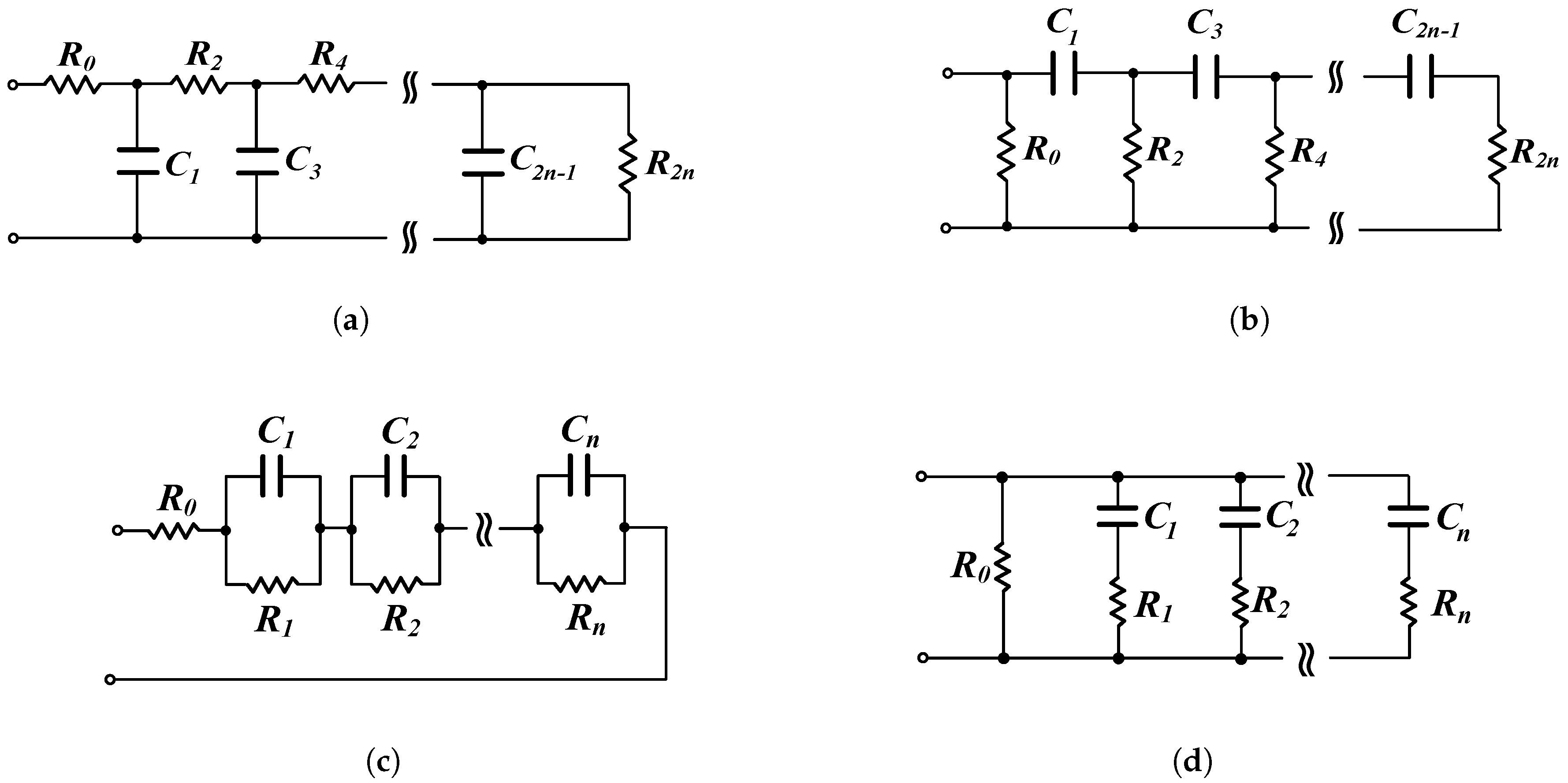
- utilizing RC networks (e.g., Cauer or Foster type) for approximating the behavior of fractional-order capacitors of the corresponding integration and/or differentiation stages, which are derived form their integer-order ones through the substitution of conventional capacitors by fractional-order capacitors [12]. This has been followed in [1,13,14,15]. The problem is that each-one of the required fractional-order capacitors must be substituted by a RC network, resulting in complicated structures in terms of passive component count. Although this is an easy procedure, in the sense that just only one design step is required for deriving the structure of the fractional-order controller, there is not capability of electronic adjustment of the characteristics of the controller.
- (b)
- utilizing approximation tools, such as Oustaloup [16], continued fraction expansion etc., of the fractional-order Laplacian operator in order to approximate the behavior of the intermediate fractional-order transfer functions of the controller (i.e., integrator and differentiator). The resulting integer-order rational transfer functions are implemented using conventional filter design techniques, such as the employment of multi-feedback or cascaded structures. This procedure has been followed in [17,18,19,20]. Considering an nth–order approximation of the Laplacian operator , with being the order of the operator, the resulting transfer function has the form of (2)with and ) being positive and real coefficients. Taking into account that a PID controller is constructed from stages of different orders, the resulting transfer function that describes the behavior of the controller will have an order equal to 2n, where n is the order of the approximation. Therefore, this solution suffers from the increased active and passive component count, worsening the performance of the system in terms of circuit complexity and power dissipation. On the other hand, it might be useful in the case where electronic adjustment of the characteristics of the controller would be required.
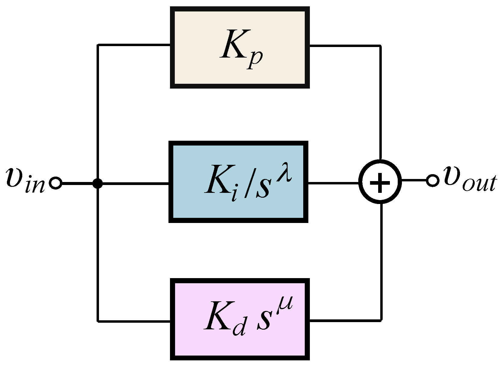
2. Proposed Implementation of Generalized Controller
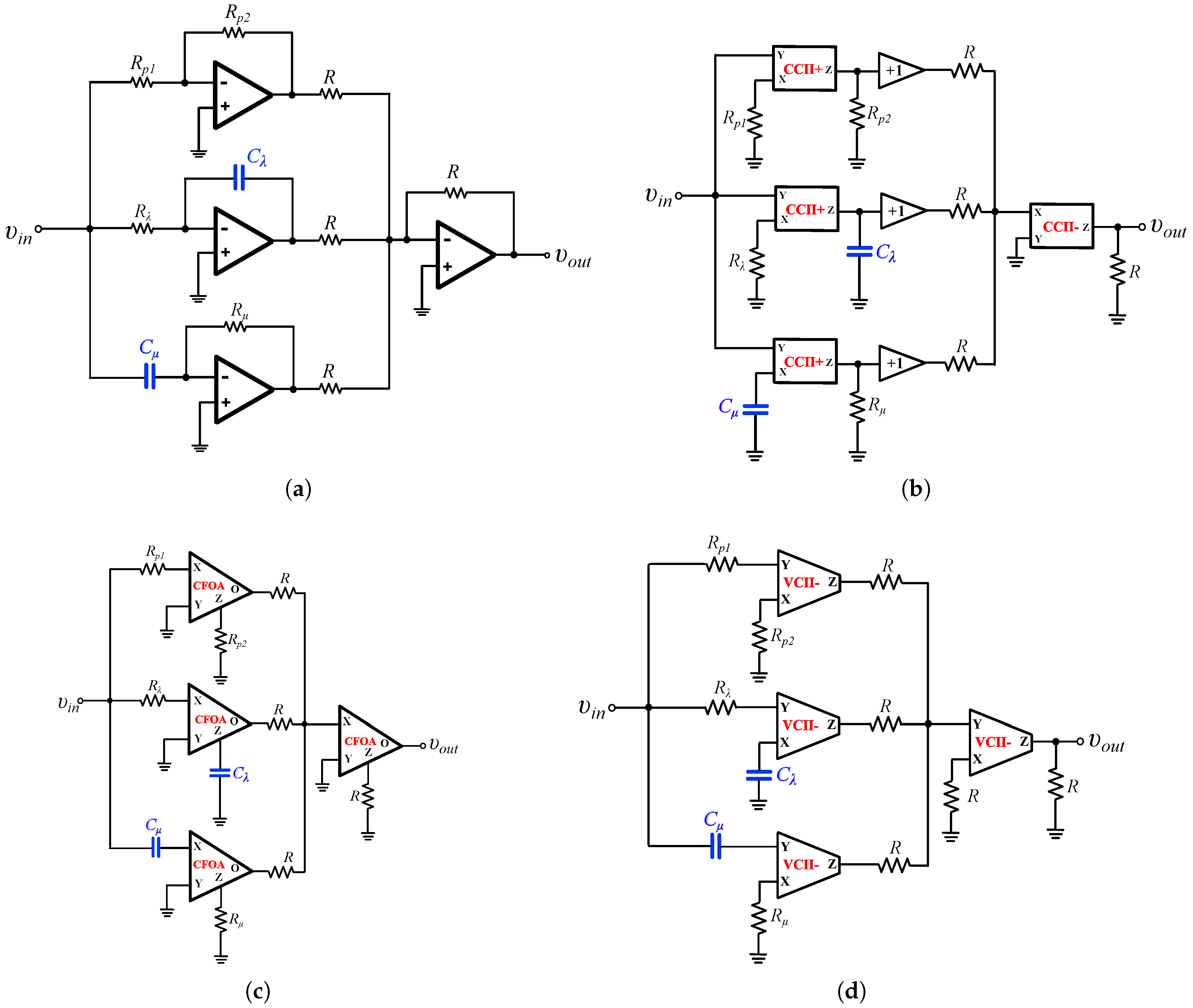
2.1. Conventional Topologies
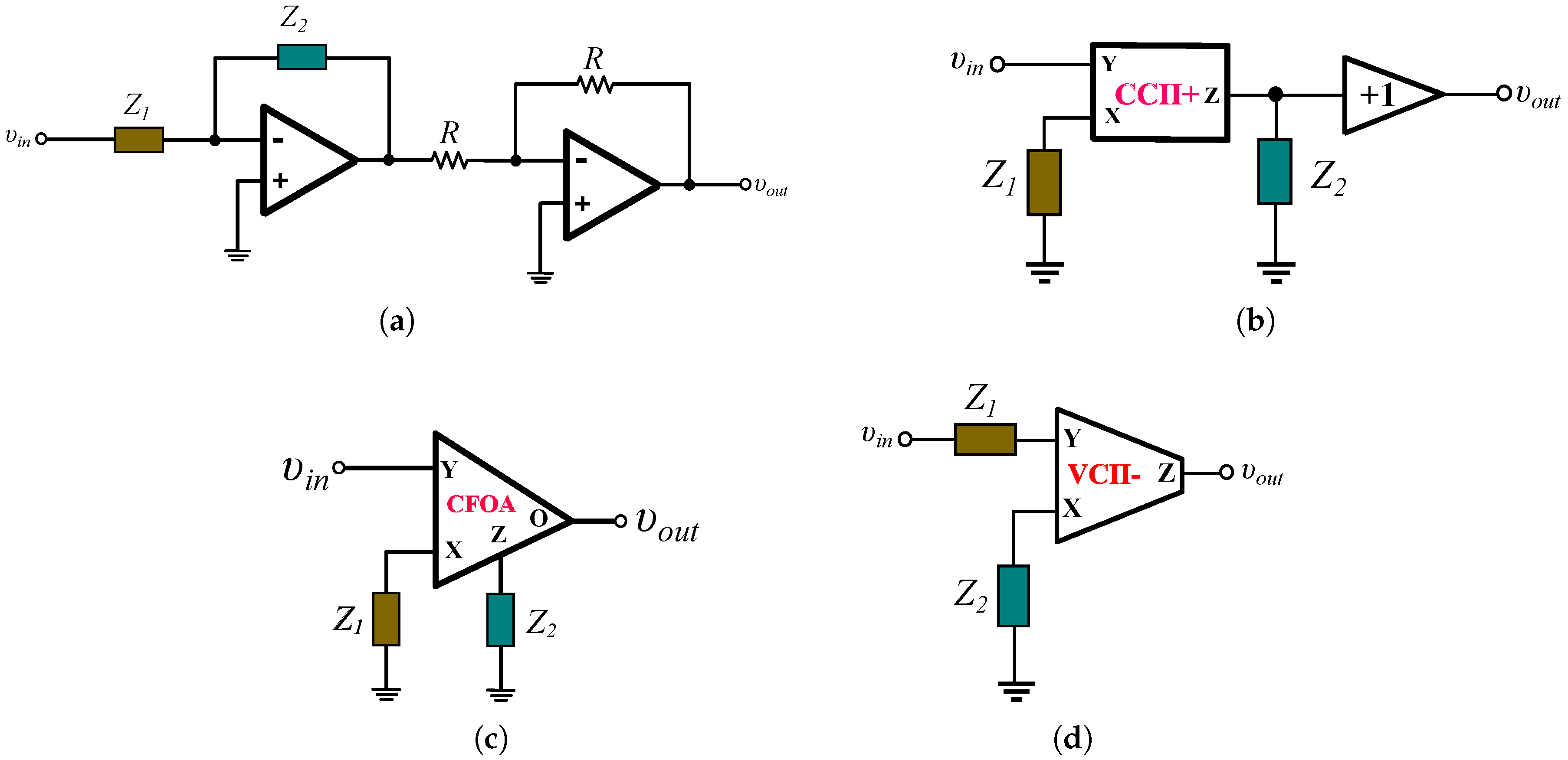
2.2. Proposed Generalized Structure
- (a)
- Approximating the intermediate terms that form the impedance using suitable tools such as the Oustaloup and the continued fraction expansion methods. Considering a nth–order approximation, the resulting order of the impedance or will be equal to and therefore the number of passive components of the RC networks will be equal to .
- (b)
- Obtain the frequency response data of the impedance, within the desired frequency range, using the MATLAB freqresp and frd functions.
- Assuming an approximation order, obtain the state-space model of the data using the command fitfrd, and then convert this model to a transfer function using the MATLAB command ss2tf.
3. Design Example: Controlling the Heart Rate in a Pacemaker
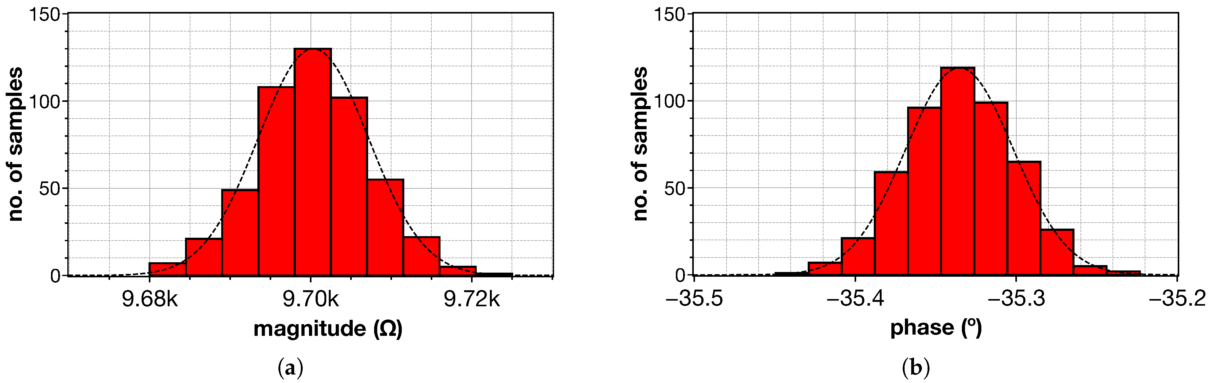
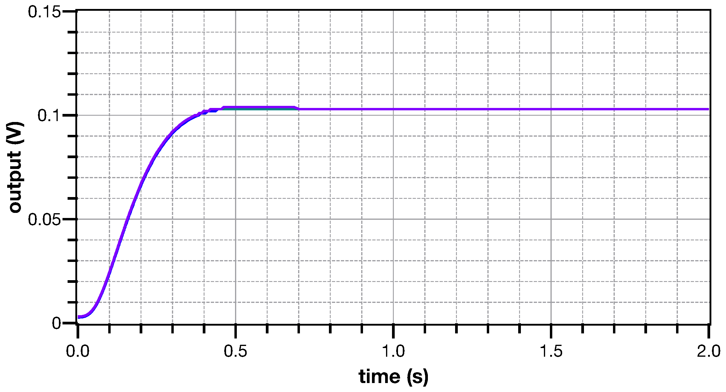
4. Simulation Results
5. Conclusions
Author Contributions
Funding
Institutional Review Board Statement
Informed Consent Statement
Data Availability Statement
Conflicts of Interest
Abbreviations
| AMS | Austria Mikro Systeme |
| CCII | Second-Generation Current Conveyor |
| CFOA | Current Feedback Operational Amplifier |
| CMOS | Complimentary Metal-Oxide Semiconductor |
| FPAA | Field Programmable Analog Array |
| FPGA | Field Programmable Gate Array |
| IAE | Integral Absolute Error |
| ITAE | Integral Time Absolute Error |
| ISE | Integral Square Error |
| ITSE | Integral Time Square Error |
| MOS | Metal-Oxide Semiconductor |
| OP-AMP | Operational Amplifier |
| PID | Fractional-Order Proportional Integral Derivative |
| RC | Resistor Capacitor |
| S-K | Sanathanan-Koerner |
| VCII | Second-Generation Voltage Conveyor |
References
- Podlubny, I.; Petráš, I.; Vinagre, B.M.; O’leary, P.; Dorčák, L. Analogue realizations of fractional-order controllers. Nonlinear Dyn. 2002, 29, 281–296. [Google Scholar] [CrossRef]
- Monje, C.A.; Chen, Y.; Vinagre, B.M.; Xue, D.; Feliu-Batlle, V. Fractional-Order Systems and Controls: Fundamentals and Applications; Springer Science & Business Media: Berlin, Germany, 2010. [Google Scholar]
- Xue, D. Fractional-order control systems. In Fractional-Order Control Systems; de Gruyter: Berlin, Germany, 2017. [Google Scholar]
- Azar, A.T.; Radwan, A.G.; Vaidyanathan, S. Fractional Order Systems: Optimization, Control, Circuit Realizations and Applications; Academic Press: Cambridge, MA, USA, 2018. [Google Scholar]
- Dastjerdi, A.A.; Vinagre, B.M.; Chen, Y.; HosseinNia, S.H. Linear fractional order controllers; A survey in the frequency domain. Annu. Rev. Control 2019, 47, 51–70. [Google Scholar] [CrossRef]
- Petráš, I. Applications in Control; Walter de Gruyter GmbH & Co KG: Berlin, Germany, 2019. [Google Scholar]
- Bingi, K.; Ibrahim, R.; Karsiti, M.N.; Hassan, S.M.; Harindran, V.R. Fractional-Order Systems and PID Controllers; Springer: Berlin, Germany, 2020. [Google Scholar]
- Muresan, C.I.; Birs, I.; Ionescu, C.; Dulf, E.H.; De Keyser, R. A Review of Recent Developments in Autotuning Methods for Fractional-Order Controllers. Fractal Fract. 2022, 6, 37. [Google Scholar] [CrossRef]
- Chevalier, A.; Francis, C.; Copot, C.; Ionescu, C.M.; De Keyser, R. Fractional-order PID design: Towards transition from state-of-art to state-of-use. ISA Trans. 2019, 84, 178–186. [Google Scholar] [CrossRef]
- Tepljakov, A.; Alagoz, B.B.; Yeroglu, C.; Gonzalez, E.; HosseinNia, S.H.; Petlenkov, E. FOPID controllers and their industrial applications: A survey of recent results. IFAC-PapersOnLine 2018, 51, 25–30. [Google Scholar] [CrossRef]
- Tepljakov, A.; Alagoz, B.B.; Yeroglu, C.; Gonzalez, E.A.; Hosseinnia, S.H.; Petlenkov, E.; Ates, A.; Cech, M. Towards industrialization of FOPID controllers: A survey on milestones of fractional-order control and pathways for future developments. IEEE Access 2021, 9, 21016–21042. [Google Scholar] [CrossRef]
- Buscarino, A.; Caponetto, R.; Graziani, S.; Murgano, E. Realization of fractional-order circuits by a constant phase element. Eur. J. Control 2020, 54, 64–72. [Google Scholar] [CrossRef]
- Domansky, O.; Sotner, R.; Langhammer, L.; Jerabek, J.; Psychalinos, C.; Tsirimokou, G. Practical design of RC approximants of constant phase elements and their implementation in fractional-order PID regulators using CMOS voltage differencing current conveyors. Circuits Syst. Signal Process. 2019, 38, 1520–1546. [Google Scholar] [CrossRef]
- Kapoulea, S.; Psychalinos, C.; Baranowski, J.; Bauer, W. CCII based realization of fractional-order PD controller for a position servo. In Proceedings of the 2019 42nd International Conference on Telecommunications and Signal Processing (TSP), Budapest, Hungary, 1–3 July 2019; pp. 102–105. [Google Scholar] [CrossRef]
- George, M.A.; Kamat, D.V.; Kurian, C.P. Electronically tunable ACO based fuzzy FOPID controller for effective speed control of electric vehicle. IEEE Access 2021, 9, 73392–73412. [Google Scholar] [CrossRef]
- Oustaloup, A.; Levron, F.; Mathieu, B.; Nanot, F.M. Frequency-band complex noninteger differentiator: Characterization and synthesis. IEEE Trans. Circuits Syst. I Fundam. Theory Appl. 2000, 47, 25–39. [Google Scholar] [CrossRef]
- Dimeas, I.; Petras, I.; Psychalinos, C. New analog implementation technique for fractional-order controller: A DC motor control. AEU-Int. J. Electron. Commun. 2017, 78, 192–200. [Google Scholar] [CrossRef]
- Sotner, R.; Jerabek, J.; Kartci, A.; Domansky, O.; Herencsar, N.; Kledrowetz, V.; Alagoz, B.B.; Yeroglu, C. Electronically reconfigurable two-path fractional-order PI/D controller employing constant phase blocks based on bilinear segments using CMOS modified current differencing unit. Microelectron. J. 2019, 86, 114–129. [Google Scholar] [CrossRef]
- Bauer, W.; Baranowski, J. Fractional PIλD Controller Design for a Magnetic Levitation System. Electronics 2020, 9, 2135. [Google Scholar] [CrossRef]
- George, M.A.; Kamat, D.V.; Indiran, T. OTA-C Realization of An Optimized FOPID Controller for BLDC Motor Speed Control. IETE J. Res. 2021, 1–19. [Google Scholar] [CrossRef]
- Nako, J.; Psychalinos, C. Heart Rate Controller Design for Cardiac Pacemaker. In Proceedings of the 2022 Panhellenic Conference on Electronics & Telecommunications (PACET), Tripolis, Greece, 2–3 December 2022; pp. 1–4. [Google Scholar]
- Tsirimokou, G. A systematic procedure for deriving RC networks of fractional-order elements emulators using Matlab. AEU-Int. J. Electron. Commun. 2017, 78, 7–14. [Google Scholar] [CrossRef]
- Safari, L.; Barile, G.; Ferri, G.; Stornelli, V. High performance voltage output filter realizations using second generation voltage conveyor. Int. J. RF Microw.-Comput.-Aided Eng. 2018, 28, e21534. [Google Scholar] [CrossRef]
- Safari, L.; Barile, G.; Stornelli, V.; Ferri, G. An overview on the second generation voltage conveyor: Features, design and applications. IEEE Trans. Circuits Syst. II Express Briefs 2018, 66, 547–551. [Google Scholar] [CrossRef]
- Safari, L.; Barile, G.; Ferri, G.; Stornelli, V. Traditional Op-Amp and new VCII: A comparison on analog circuits applications. AEU-Int. J. Electron. Commun. 2019, 110, 152845. [Google Scholar] [CrossRef]
- Safari, L.; Yuce, E.; Minaei, S.; Ferri, G.; Stornelli, V. A second-generation voltage conveyor (VCII)–based simulated grounded inductor. Int. J. Circuit Theory Appl. 2020, 48, 1180–1193. [Google Scholar] [CrossRef]
- Yesil, A.; Minaei, S. New simple transistor realizations of second-generation voltage conveyor. Int. J. Circuit Theory Appl. 2020, 48, 2023–2038. [Google Scholar] [CrossRef]
- Yuce, E.; Safari, L.; Minaei, S.; Ferri, G.; Barile, G.; Stornelli, V. A New Simulated Inductor with Reduced Series Resistor Using a Single VCII±. Electronics 2021, 10, 1693. [Google Scholar] [CrossRef]
- Bingi, K.; Ibrahim, R.; Karsiti, M.N.; Hassam, S.M.; Harindran, V.R. Frequency response based curve fitting approximation of fractional-order PID controllers. Int. J. Appl. Math. Comput. Sci. 2019, 29, 311–326. [Google Scholar] [CrossRef]
- Arunachalam, S.P.; Kapa, S.; Mulpuru, S.K.; Friedman, P.A.; Tolkacheva, E.G. Intelligent fractional-order PID (FOPID) heart rate controller for cardiac pacemaker. In Proceedings of the 2016 IEEE Healthcare Innovation Point-of-Care Technologies Conference (HI-POCT), Cancun, Mexico, 9–11 November 2016; pp. 105–108. [Google Scholar]
- Bajpai, S.; Alam, M.; Ali, M. Intelligent Heart Rate Controller using Fractional Order PID Controller Tuned by Genetic Algorithm for Pacemaker. Int. J. Eng. Res. Technol. 2017, 6, 715–720. [Google Scholar]
- Momani, S.; Batiha, I.M.; El-Khazali, R. Design of PIλDδ-Heart Rate Controllers for Cardiac Pacemaker. In Proceedings of the 2019 IEEE International Symposium on Signal Processing and Information Technology (ISSPIT), Ajman, United Arab Emirates, 10–12 December 2019; pp. 1–5. [Google Scholar]
- Tolba, M.F.; AboAlNaga, B.M.; Said, L.A.; Madian, A.H.; Radwan, A.G. Fractional order integrator/differentiator: FPGA implementation and FOPID controller application. AEU-Int. J. Electron. Commun. 2019, 98, 220–229. [Google Scholar] [CrossRef]
- Singh, K. Load frequency regulation by de-loaded tidal turbine power plant units using fractional fuzzy based PID droop controller. Appl. Soft Comput. 2020, 92, 106338. [Google Scholar]
- Silva-Juárez, A.; Tlelo-Cuautle, E.; De La Fraga, L.G.; Li, R. FPAA-based implementation of fractional-order chaotic oscillators using first-order active filter blocks. J. Adv. Res. 2020, 25, 77–85. [Google Scholar] [CrossRef] [PubMed]
- Tlelo-Cuautle, E.; Pano-Azucena, A.D.; Guillén-Fernández, O.; Silva-Juárez, A. Analog/Digital Implementation of Fractional Order Chaotic Circuits and Applications; Springer: Berlin/Heidelberg, Germany, 2020. [Google Scholar]
- Gude, J.J.; García Bringas, P. A Novel Control Hardware Architecture for Implementation of Fractional-Order Identification and Control Algorithms Applied to a Temperature Prototype. Mathematics 2022, 11, 143. [Google Scholar] [CrossRef]


| Topology | Number of Active Elements | Number of Resistors | Number of Capacitors |
|---|---|---|---|
| Figure 2a | 4 | ||
| Figure 2b | 4 (plus 3 buffers) | ||
| Figure 2c | 4 | ||
| Figure 2d | 4 |
| Topology | Number of Active Elements | Number of Resistors | Number of Capacitors |
|---|---|---|---|
| Figure 4a | 2 | n | |
| Figure 4b | 1 (plus 1 buffer) | n | |
| Figure 4c | 1 | n | |
| Figure 4d | 1 | n |
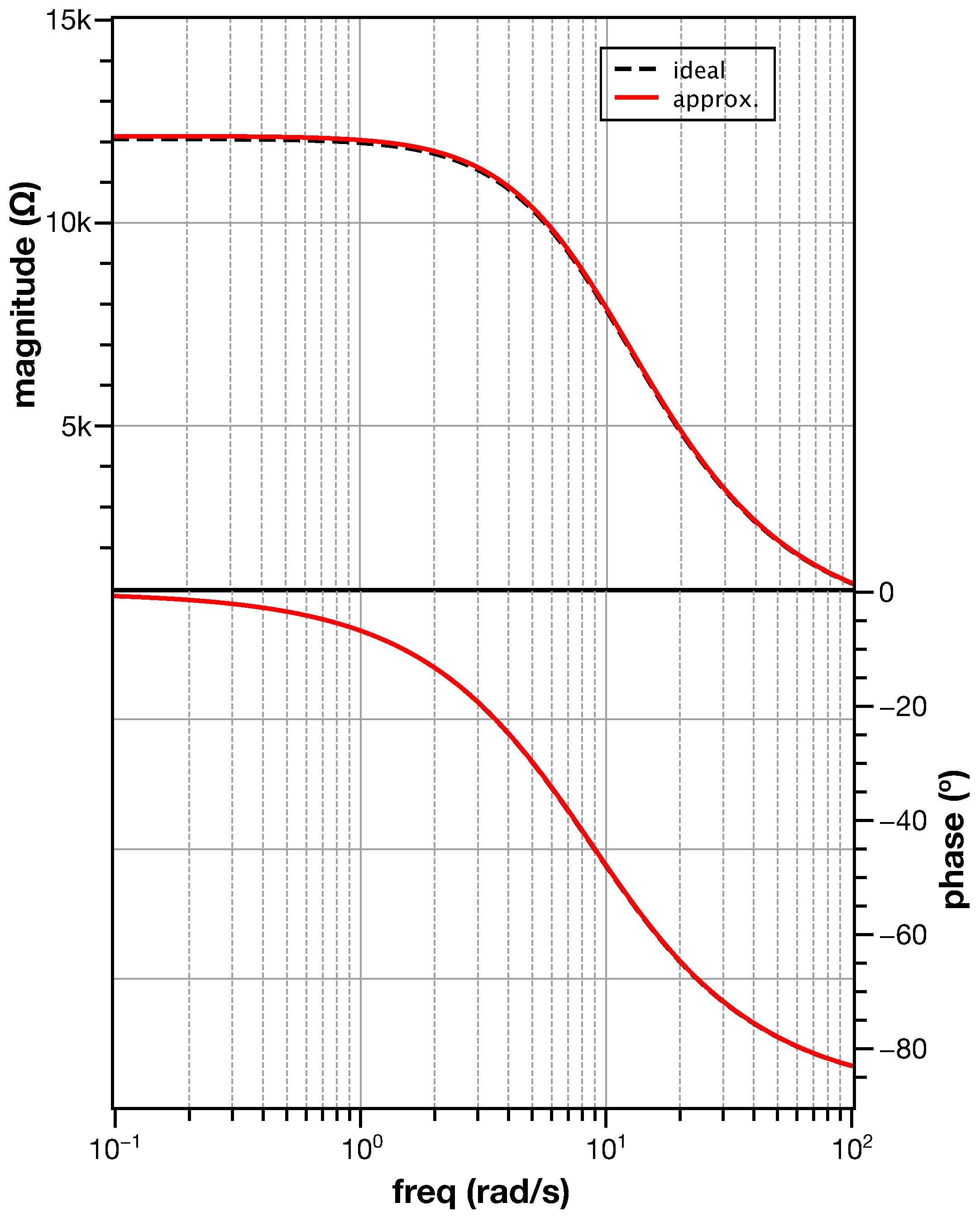
| Parameter | Theoretical | Approximation |
|---|---|---|
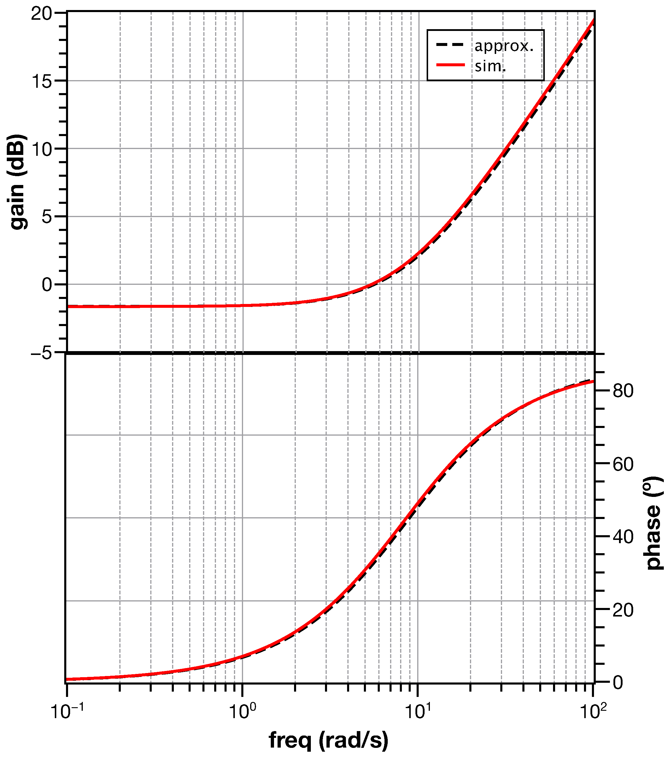
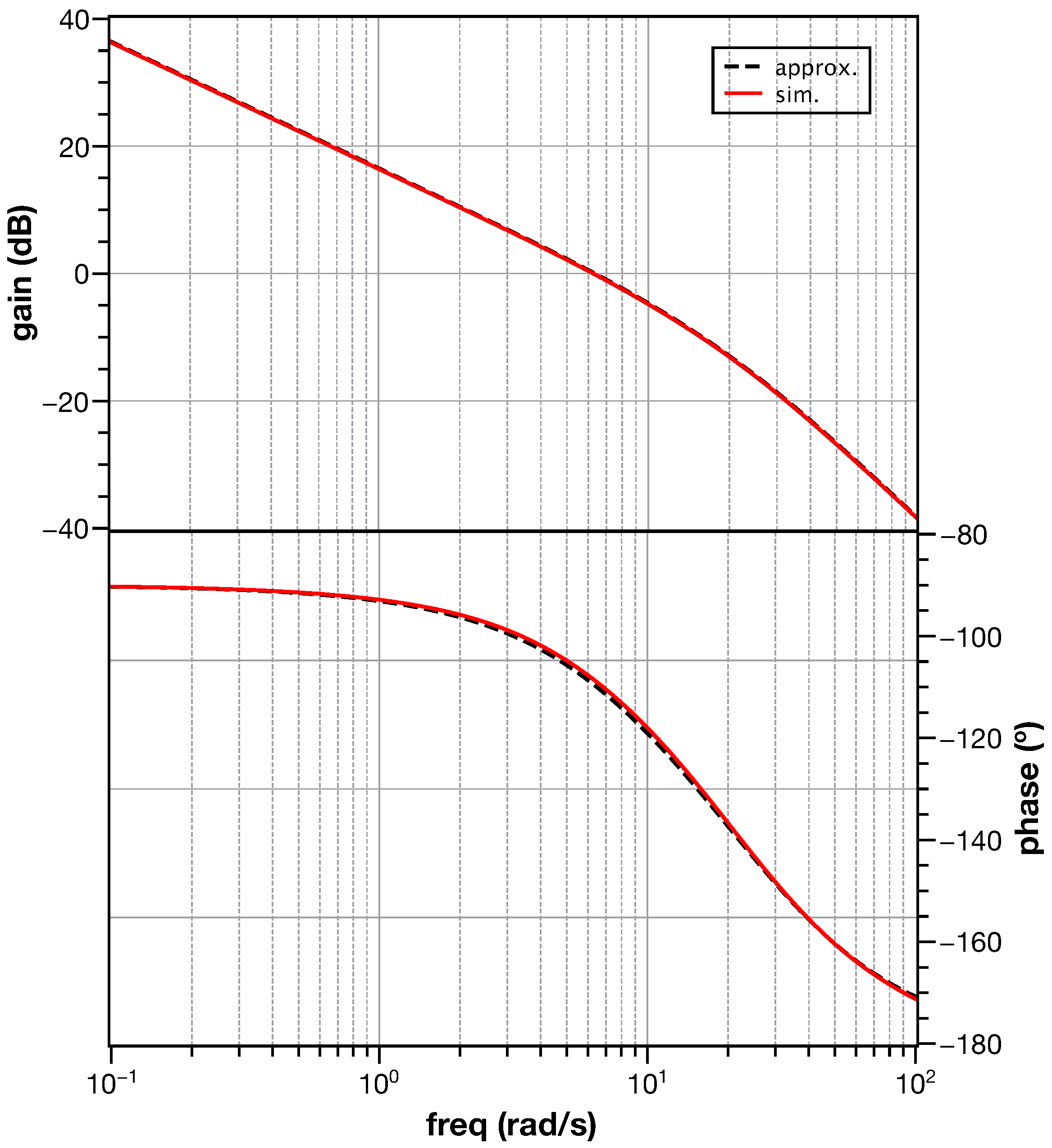
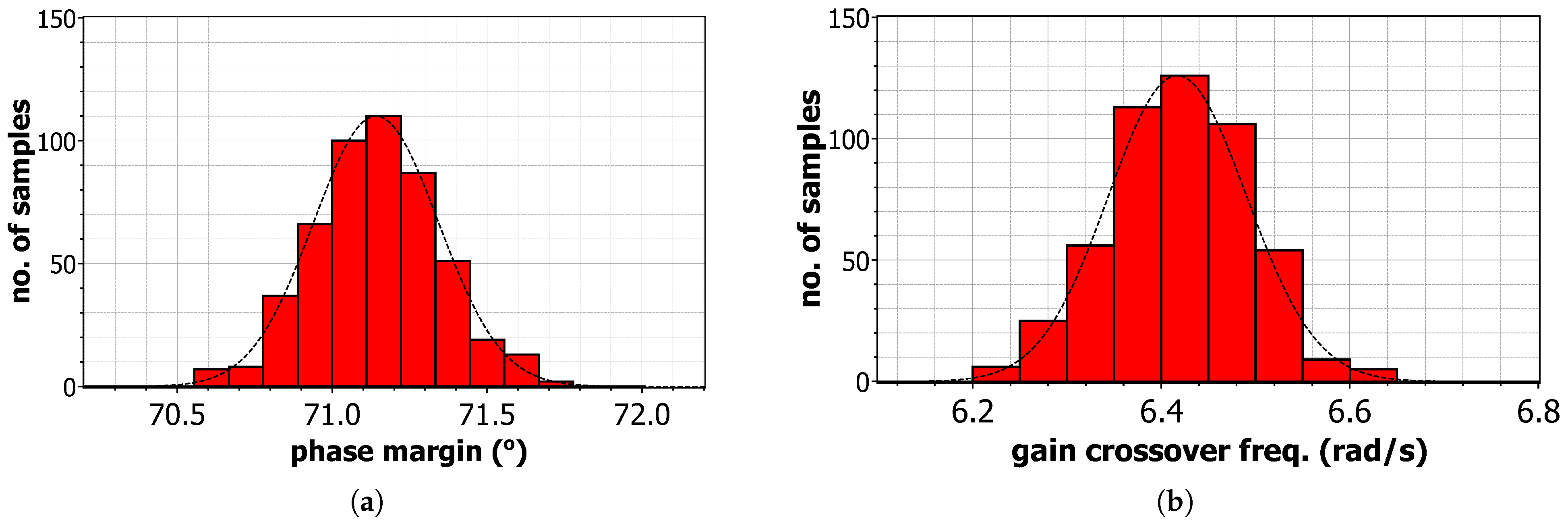
| Phase margin () | 70.39 | 70.34 |
| Gain crossover frequency (rad/s) | 6.34 | 6.34 |
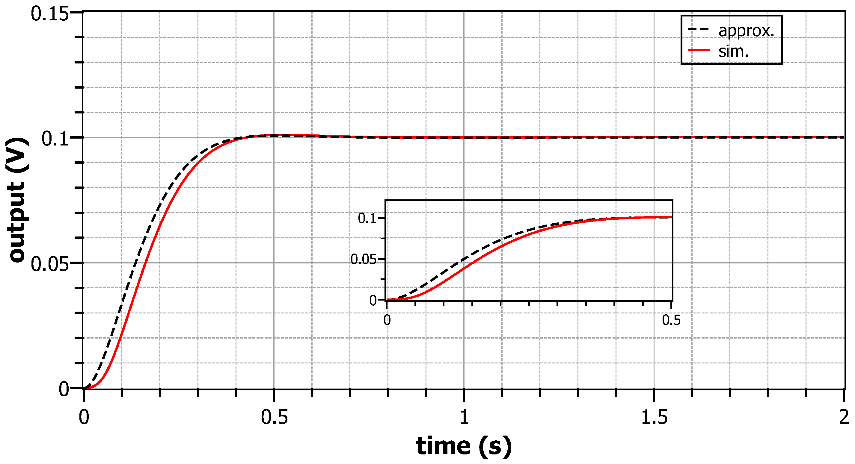
| Rise-time (ms) | 308.1 | 236.4 |
| Settling-time (ms) | 472.7 | 355.4 |
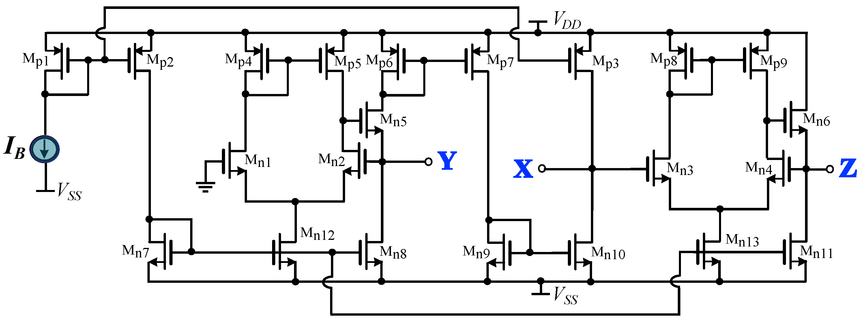
| Transistor | Aspect Ratio (μm /μm ) |
|---|---|
| Mp1–Mp9 | 200/2 |
| Mn1–Mn4 | 20/2 |
| Mn5–Mn6 | 20/0.4 |
| Mn7–Mn11 | 2/2 |
| Mn12–Mn13 | 4/2 |
| Element | Cauer Type-I | Cauer Type-II |
|---|---|---|
| 15.8 | 12.1 k | |
| 1 k | 931 | |
| 1.96 k | 118 | |
| 215 | 18.7 | |
| 9.09 F | 9.76 F | |
| 15.8 F | 178 F | |
| 953 F | 196 F |
| Element | Foster Type-I | Foster Type-II |
|---|---|---|
| 15.8 | 12.1 k | |
| 187 | 15.8 | |
| 10.7 k | 60.4 k | |
| 1.24 k | 511 k | |
| 127 F | 9.09 F | |
| 10.2 F | 0.412 F | |
| 174 F | 0.392 F |
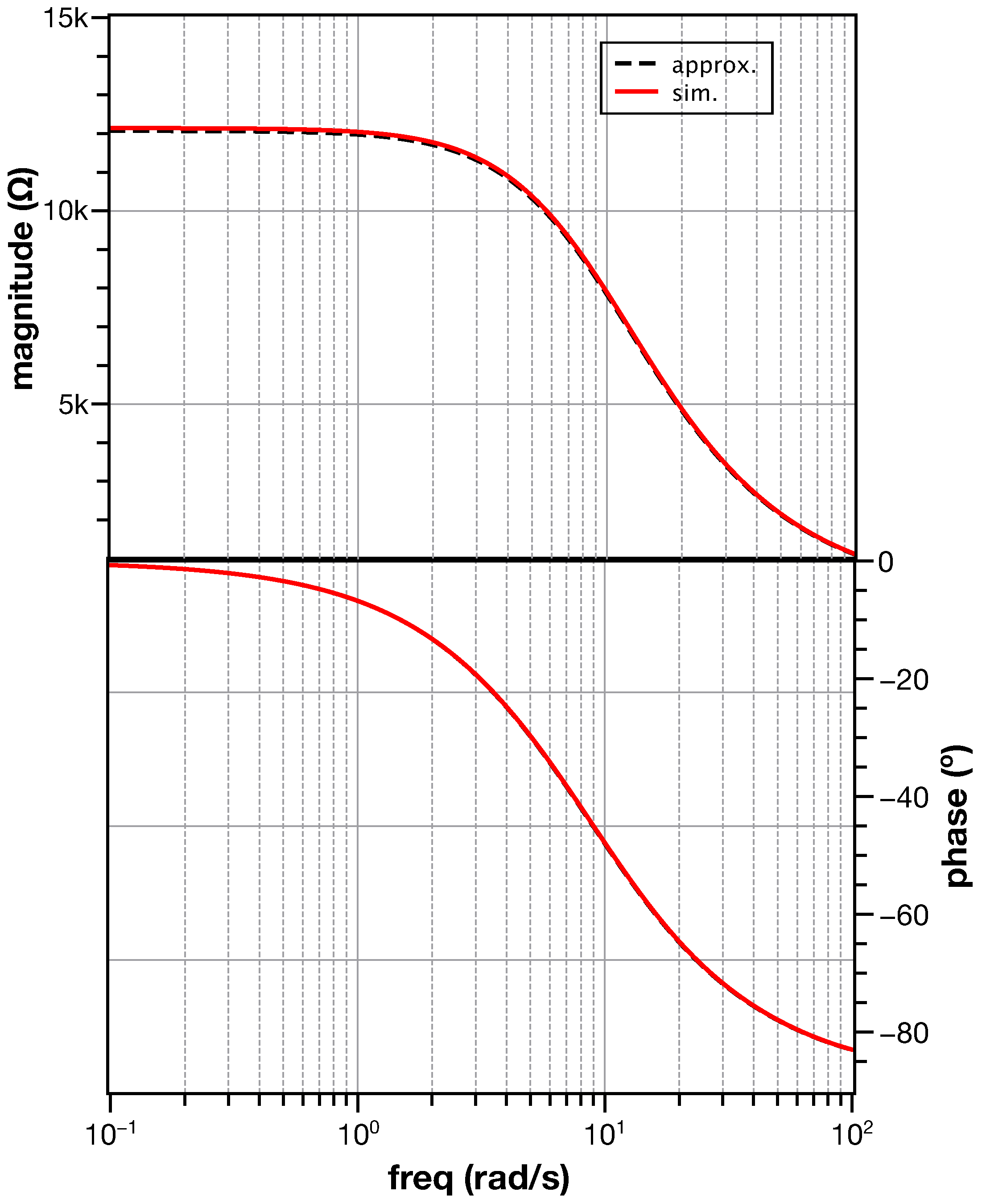
| Parameter | Approximation | Simulation |
|---|---|---|
| Phase margin () | 70.34 | 71.14 |
| Gain crossover frequency (rad/s) | 6.34 | 6.42 |
| Rise-time (ms) | 236.4 | 230.6 |
| Settling-time (ms) | 355.4 | 341.5 |
Disclaimer/Publisher’s Note: The statements, opinions and data contained in all publications are solely those of the individual author(s) and contributor(s) and not of MDPI and/or the editor(s). MDPI and/or the editor(s) disclaim responsibility for any injury to people or property resulting from any ideas, methods, instructions or products referred to in the content. |
© 2023 by the authors. Licensee MDPI, Basel, Switzerland. This article is an open access article distributed under the terms and conditions of the Creative Commons Attribution (CC BY) license (https://creativecommons.org/licenses/by/4.0/).
Share and Cite
Nako, J.; Psychalinos, C.; Elwakil, A.S. Minimum Active Component Count Design of a PIλDμ Controller and Its Application in a Cardiac Pacemaker System. J. Low Power Electron. Appl. 2023, 13, 13. https://doi.org/10.3390/jlpea13010013
Nako J, Psychalinos C, Elwakil AS. Minimum Active Component Count Design of a PIλDμ Controller and Its Application in a Cardiac Pacemaker System. Journal of Low Power Electronics and Applications. 2023; 13(1):13. https://doi.org/10.3390/jlpea13010013
Chicago/Turabian StyleNako, Julia, Costas Psychalinos, and Ahmed S. Elwakil. 2023. "Minimum Active Component Count Design of a PIλDμ Controller and Its Application in a Cardiac Pacemaker System" Journal of Low Power Electronics and Applications 13, no. 1: 13. https://doi.org/10.3390/jlpea13010013