1. Introduction
The aging of infrastructure in numerous nations, along with growing demands on loads, has made reinforcing existing reinforced concrete structures an important subject [
1,
2]. Reinforced concrete beams are prone to failing in two different ways: flexural failure and shear failure, with shear failure often being sudden and brittle. To avoid brittle failure and ensure ductile failure (flexural failure), concrete beams need to achieve a sufficient shear strength through shear strengthening [
3]. Years of research have demonstrated that CFRP possesses several advantages, such as being lightweight and possessing high strength, corrosion resistance, fatigue resistance, low creep, electromagnetic insulation, and good seismic performance [
4,
5]. As a result, CFRP has recently been extensively employed in improving the shear performance of concrete structures, and some advancements have been achieved [
6,
7,
8].
Compared to flexural strengthening, shear strengthening with CFRP presents a more difficult challenge due to an insufficient bond length and reduced ductility [
9]. Zomorodian et al. performed experimental research on the method of shear reinforcement for side-bonding CFRP. The failure of the reinforced beams often results from CFRP debonding, which typically leads to a limitation in the beams’ ductility [
10,
11], and the enhancement in the shear performance is quite minimal [
12]. Chen et al. investigated the U-wrap CFRP technique [
9,
13,
14] and found that the bond length of the CFRP in this technique was constrained by the cross-sectional dimensions of the concrete structure [
15,
16]. In addition, Ammar et al. introduced near-surface-mounted (NSM) technology to shear-strengthening research [
17,
18], which can effectively enhance the shear-carrying capacity and deformation capacity when structures fail [
19,
20]. However, when the CFRP ratio is too high, it may cause the failure mode of reinforced beams to change to concrete cover delamination, resulting in the premature failure of the specimens [
21,
22,
23]. A high relative slip leads to deterioration in the bonding performance between the CFRP and concrete, limiting the full utilization of the tensile strength of the CFRP.
Conventional passive strengthening methods employed to enhance the shear performance in structures are not effective enough in controlling the cracks. To address this limitation, prestressing is applied to carry out active reinforcement, mitigate the high strength-to-modulus ratio of CFRP tendons, and improve the distribution of the internal forces within the structure. In the exploration of prestressed-CFRP shear reinforcement technology, various methods have been employed to apply prestress to CFRP that is bonded to beams, such as tensioned circular CFRP strips [
24], self-locking tensioning [
25], and turning-block tensioning [
26]. Zhou et al. [
27] conducted a study on the shear strengthening of U-shaped CFRP strips with bonded tendons and found that the prestressed reinforcement outperformed the pure-adhesive strengthening in suppressing the primary diagonal crack propagation, delaying the yielding of stirrups, and enhancing the utilization of the stirrups’ plasticity. This method significantly increased the fiber strength utilization and notably improved the shear-carrying capacity of beams. Moreover, under similar conditions, higher prestress levels or fiber ratios led to better overall performance in reinforced beams. Pen et al. [
28] investigated the mechanical properties and failure modes of prestressed NSM CFRP shear strengthening. They discovered that the prestressed NSM CFRP shear reinforcement substantially enhanced the shear crack loads and shear-carrying capacity. The prestress effectively constrained the rate and width of the shear crack propagation. These research results demonstrate that the use of prestressing technology successfully limits the growth of diagonal cracks and improves the ability of the specimens to withstand shear forces. The initial degree of prestress exerts a substantial influence on the reinforcement effect.
Among the numerous studies on CFRP shear strengthening, the majority focus on adhesive bonding and NSM techniques, with research on external non-bonded prestressed CFRP tendon shear-strengthening techniques being relatively limited. Additional data are needed to comprehensively assess the shear performance of externally prestressed reinforced concrete beams. This paper presents a novel shear-strengthening technique involving the mechanical fastening of CFRP tendons to a beam using screws, anchorages, and reaction steel plates. In this study, five reinforced concrete beams with strong bending and weak shear configurations were fabricated, with four of them reinforced using externally non-bonded prestressed CFRP tendons for shear strengthening. The study investigated the influences of the prestress level of the CFRP tendons and beam damage on both the shear-strengthening effect and the propagation of diagonal cracks through model experiments. Utilizing the truss–arch model, a method for calculating the shear capacity of the reinforced beams is proposed and validated against experimental results, providing valuable insights for engineering applications.
3. Results and Analysis
3.1. Results
The tests utilized two-point symmetric loading, but due to an error during the field operation, only one end of the specimen was damaged when it reached the ultimate state. The test phenomenon discussed in this paper pertains to the damaged end.
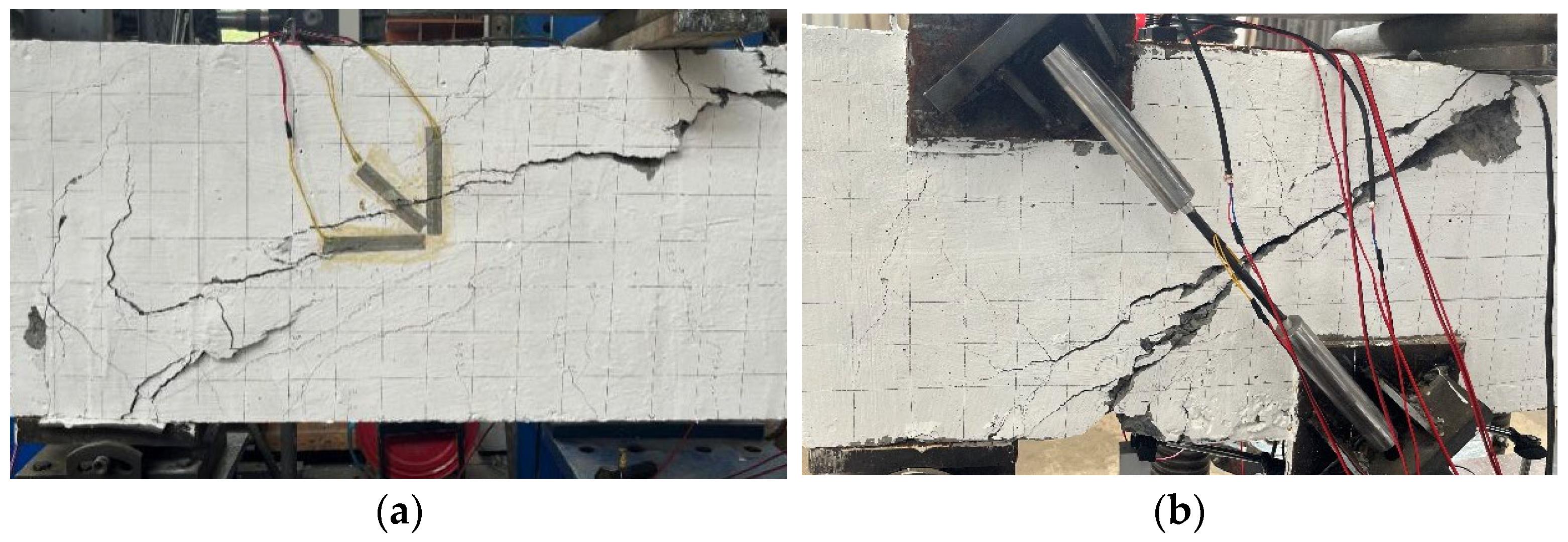
The failure mode of CB-0-0 exhibited a typical shear–compression failure: after the stirrups yielded, the deflection of the specimen rapidly increased until structural failure, while the longitudinal reinforcement remained in the elastic range. In specimen CB-0-0, vertical bending cracks emerged in the pure bending zone when loaded to around 80 kN. At a load of 160 kN, the shear zone exhibited the first diagonal crack, which progressively expanded as the load increased. When the load reached 481 kN, the diagonal crack expanded rapidly, leading to the failure of the specimen. The final failure pattern is illustrated in
Figure 5a.
The failure processes of specimens RB-0-0, RB-400-0, and RB-800-0 showed similarities. Using specimen RB-400-0 as an illustration, vertical bending cracks resembling those observed in specimen CB-0-0 also emerged at around 80 kN. The first diagonal crack visible at 260 kN was located at a height between one-half and one-third of the shear span, with an angle roughly parallel to the line connecting the support and loading points. As the load increased, several new diagonal cracks appeared successively, and the existing diagonal cracks extended toward both ends of the support and loading points, resulting in a major diagonal crack. After the stirrups yielded, the deflection of the specimen continued to increase even if the load remained constant in the short term. Concrete spalling happened concomitantly, and the increasing rate in the width of the main diagonal crack and the tension of the CFRP tendon accelerated. When the specimen collapsed imminently, the load stopped increasing. Within a brief time, the concrete adjacent to the loading point in the shear span disintegrated, resulting in the specimen’s failure.
Figure 5b shows the failure situation, in which the CFRP tendons did not fracture and were projected through diagonal cracks while the anchoring devices remained undamaged.
Prior to performing the static load test, specimen RB-400-0.2 was subjected to a load of 270 kN before reinforcement, resulting in a diagonal crack measuring 0.2mm in width. After installing prestressed CFRP tendons, the pre-existing diagonal cracks were completely sealed. In the static load test, the pre-existing diagonal cracks started to expand slowly from the first loading level. When the diagonal crack width measured 0.2 mm again, the load reached 320 kN, representing an 18.5% increase compared to the state without reinforcement. This suggests that using prestressed CFRP tendons could limit the growth of pre-existing diagonal cracks in the specimen. The phenomenon of RB-400-0.2 after the significant expansion of the diagonal cracks was similar to other reinforced beams.
The experimental results are presented in
Table 3. The findings indicate that using prestressed CFRP tendons for shear reinforcement led to a significant augmentation in the cracking load, yield load, and ultimate load. The yield loads of RB-0-0, RB-400-0, and RB-800-0 increased by 20.8%, 38%, and 75%, respectively, compared to CB-0-0. The ultimate loads had respective increases of 47.71%, 70.27%, and 87.32%. This phenomenon suggests that as the prestress level of the CFRP tendons increased, the yield load and ultimate load of the specimen also increased, leading to improved reinforcement effects. The shear capacities of specimens RB-400-0 and RB-400-0.2 were similar, suggesting that the initial damage in the shear zone did not have a substantial effect on the shear capacity.
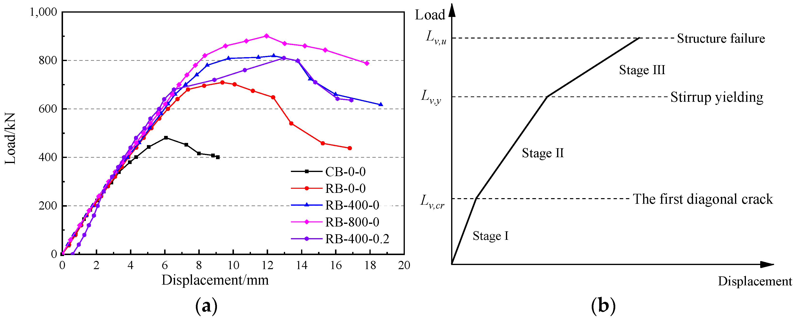
3.2. Analysis of Load–Vertical Displacement of Loading Points
We obtained the vertical displacement of the loading point at every load level and then graphed the load–displacement curves for all specimens, as depicted in
Figure 6. The vertical displacement values were obtained by averaging the readings from two LVDTs positioned at the loading points, corrected in the vertical direction to reduce the influence of load eccentricity and loading beam deformation. The load–displacement behavior can be roughly divided into three stages of linear response.
During Stage I, diagonal cracks did not appear in the shear zone of any specimen, and the shear stiffness remained constant. The load–displacement curves of all undamaged specimens coincide, showing the highest shear stiffness.
In Stage II, the shear stiffness of the specimens decreased when diagonal cracks occurred in the shear zone. The concrete’s contribution to the shear strength no longer increased, while both stirrups and CFRP tendons started to significantly contribute to the shear capacity. Comparing CB-0-0 with RB-0-0, it is evident that the reinforced beams exhibited higher shear stiffness, a result indicating the additional stiffness provided by the CFRP tendons. Upon comparing the curves of RB-0-0, RB-400-0, and RB-800-0, it is noted that their shear stiffness in Stage II was similar. However, the load at which diagonal cracking occurred—termed the “change point”—rose with increased prestress, enhancing the overall stiffness of specimens under identical loads. Therefore, the enhancement in shear stiffness due to the CFRP tendons was positively correlated with the level of prestress. Comparing RB-400-0 to RB-400-0.2 reveals that the pre-existing diagonal cracks significantly reduced the shear stiffness before reaching the yield load, but did not markedly change the yield load itself or the displacement at the loading points. This suggests that the pre-cracks had minimal impact on the shear capacity.
Upon entering Stage III, the stirrups in the shear zone yielded, leading to a further decrease in the shear stiffness, quicker expansion of the diagonal cracks, and a more pronounced change in the displacements at the loading points. In contrast to the immediate failure observed in CB-0-0 after the stirrups yielded, the reinforced beams maintained a considerable level of stability, and the failure displacement of the loading point was considerably greater than in CB-0-0, leading to an enhancement in ductility. This is because the CFRP tendons that had not reached their ultimate strength could withstand increased shear. Throughout these stages, the shear stiffness diminished progressively, indicating a significant correlation between the shear stiffness of the reinforced beams with CFRP tendons and the cracking state within the shear span.
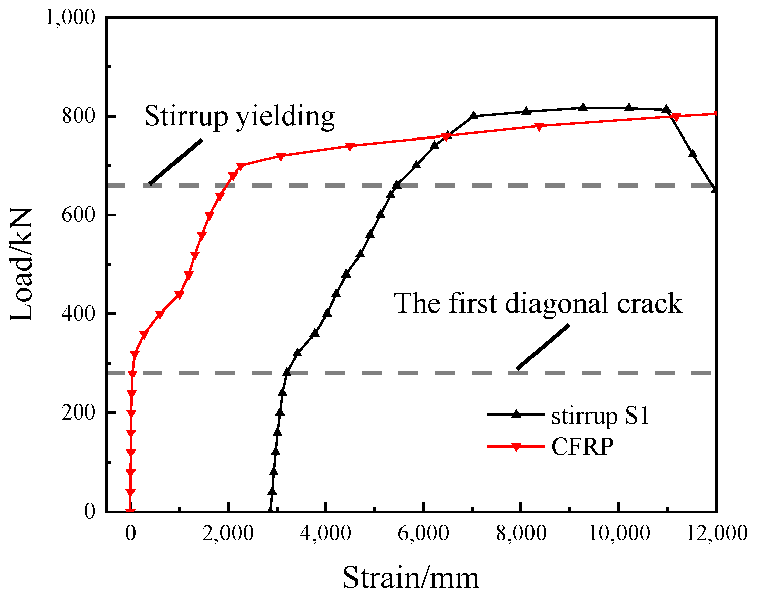
3.3. Stirrup and CFRP Strain Analysis
As depicted in
Figure 7, we used RB-400-0 as an example to introduce strain variations in the stirrups (S1) and CFRP tendons—both on the same side—before the first diagonal crack occurred. The strain in the stirrup tended toward 0, suggesting that it was not actively contributing to the resistance against the shear forces, while the CFRP tendon showed negligible deformation. Following the emergence of the diagonal crack, the growth rates of the strains in both the stirrups and the CFRP tendons increased. The yielding of the stirrup led to a further increase in the strain rate of the CFRP tendons. Close to the ultimate load, the slope of the load–strain curve for the CFRP tendon approaches zero.
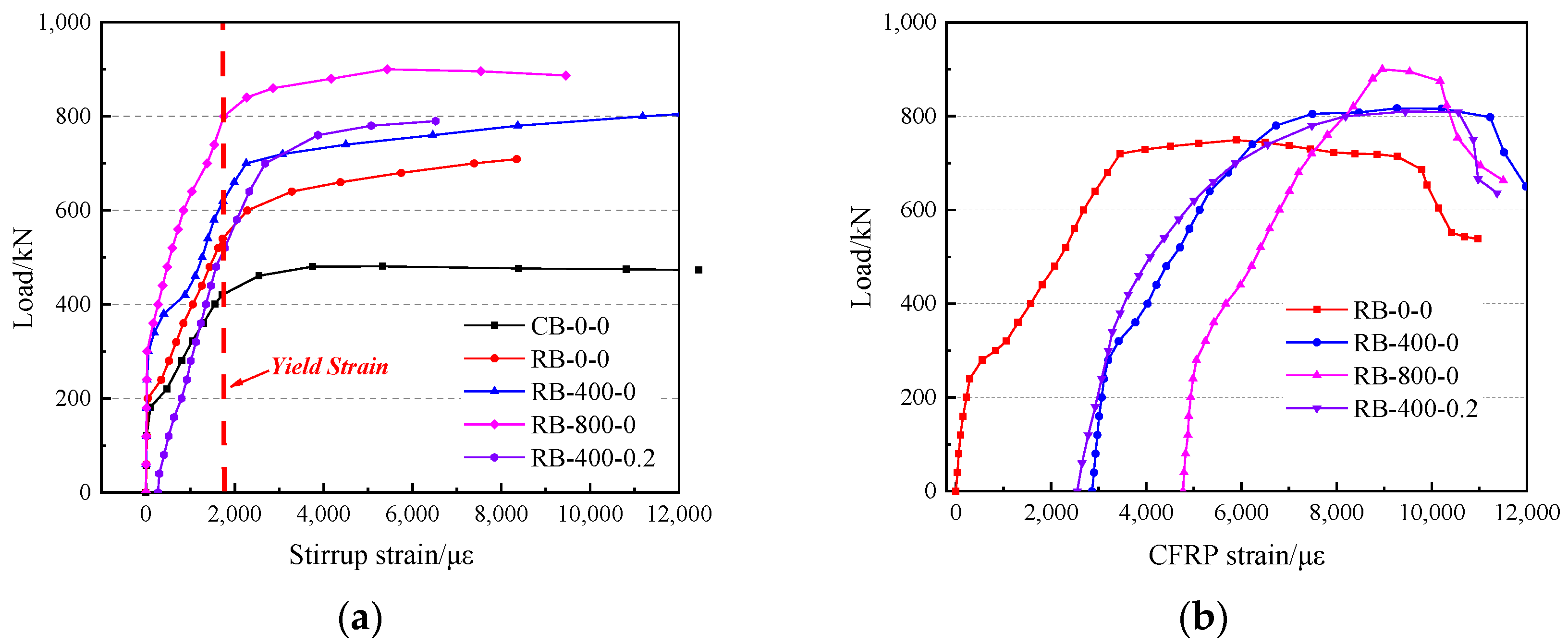
Figure 8a depicts the load–strain curves for stirrup S1 in all specimens. It can be seen that at loads greater than the cracking load for CB-0-0, the strain in the reinforced beams’ stirrups significantly was reduced compared to that in CB-0-0. This suggests that the CFRP tendons assumed the portion of the shear force that would initially be carried by the stirrups. The stirrup S1 in beam CB reached the yield state with a load of 424 kN. Compared to the CB beam’s stirrup S1, which yielded at a load of 424 kN, the stirrups S1 in the reinforced beams RB-0-0, RB-400-0, and RB-800-0 yielded at loads of 544 kN, 624 kN, and 760 kN, respectively—increases of 38%, 47%, and 79%. Therefore, the CFRP tendons effectively alleviated the stress on the stirrups, thereby decelerating the increase in the stirrup strain. In addition, the higher the level of prestress, the more significant the reinforcement effect.
Figure 8b depicts the load–strain curves for the CFRP tendons in all reinforced beams. In specimen RB-400-0.2, the stirrup’s strain rate was considerably higher than that in the other reinforced beams before the diagonal crack formed. Furthermore, within the same reinforced beam, the strain growth rate of both the CFRP tendons and the stirrups varied similarly in terms of load. This indicates that the CFRP tendons always worked in conjunction with the stirrups, jointly contributing to the increase in shear capacity.
Table 4 lists the tensile strength exerted by the CFRP tendons in the static load testing. Under the conditions of prestressing, the CFRP tendon’s utilization of the tensile strength increased by over 20% with the ultimate load. When the specimen completely failed, the average maximum utilization of the CFRP tendon’s strength was 87%. This demonstrates the effective utilization of CFRP tendons’ strength.
3.4. Analysis of Crack Growth
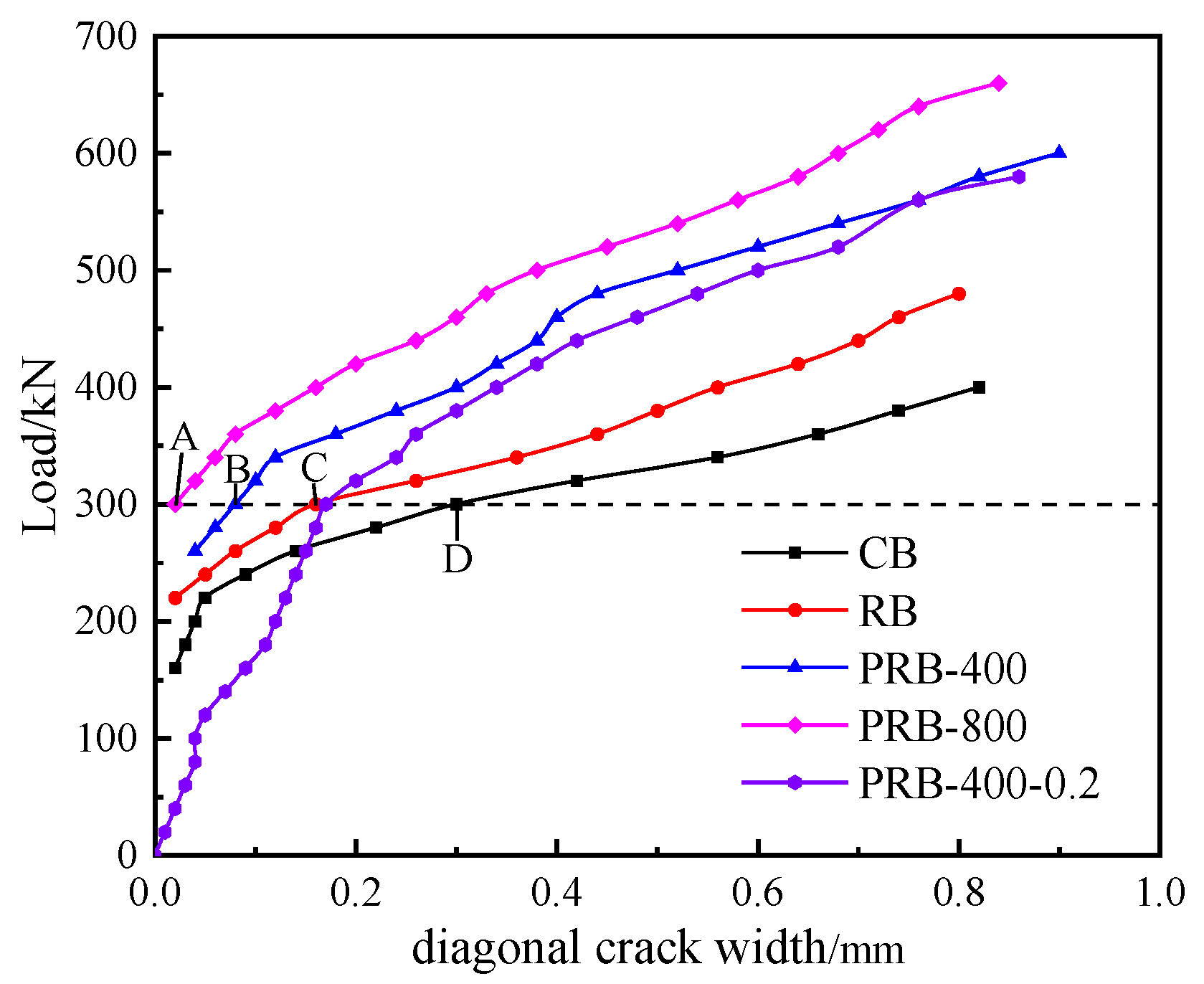
Figure 9 illustrates the width of the diagonal cracks at various load levels. The results indicate that applying CFRP tendon shear reinforcement to undamaged specimens significantly increased the cracking load and delayed the onset of inclined crack formation. As the level of prestress increased, the cracking load of the diagonal cracks also increased, demonstrating that the prestressed CFRP tendons provided a reserve of shear capacity for the specimen.
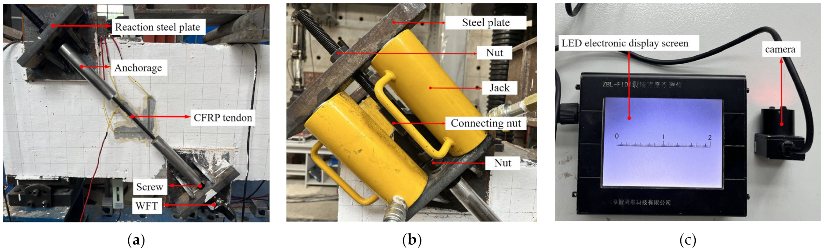
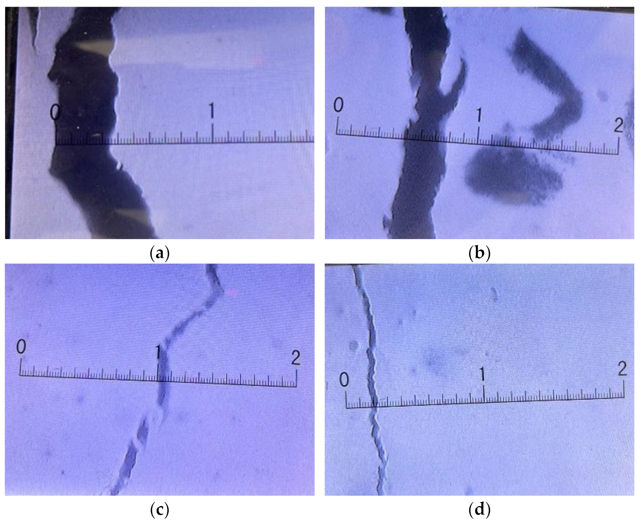
Figure 10 shows the measured maximum diagonal crack widths of specimens CB-0-0, RB-0-0, RB-400-0, and RB-800-0 at a load of 300 kN, as displayed on the LED electronic screen of the microscope for crack measurement. These readings correspond to points A, B, C, and D in
Figure 8. A significant restrictive effect of CFRP tendons on the diagonal crack width development was observed. Moreover, under the same load, larger prestress resulted in smaller diagonal crack widths. The statistics presented in
Table 5 provide additional confirmation of this theory by presenting crack widths of 0.2 mm, 0.3 mm, 0.5 mm, and 0.8 mm.
Comparing the data for RB-400-0 and RB-400-0.2 in
Table 5, it can be inferred that with CFRP tendons at the same prestress level, the impact of initial damage in the shear zone on crack width gradually diminished as the load increased. When the crack widths were relatively large, the impact of the initial damage on the crack resistance of the specimens can be negligible.
4. Calculation
This section introduces a shear design model to predict the shear capacity of beams reinforced with externally unbonded prestressed CFRP tendons. Based on the analysis of the test results, when the stirrups yield, there is a significant decrease in the shear stiffness, posing challenges for accurately predicting the shear deformation. This complicates the accurate calculation of incremental strains on CFRP tendons. Therefore, this study emphasizes the shear capacity at the point of the stirrups yielding, aligning with the yielding load of the specimens.
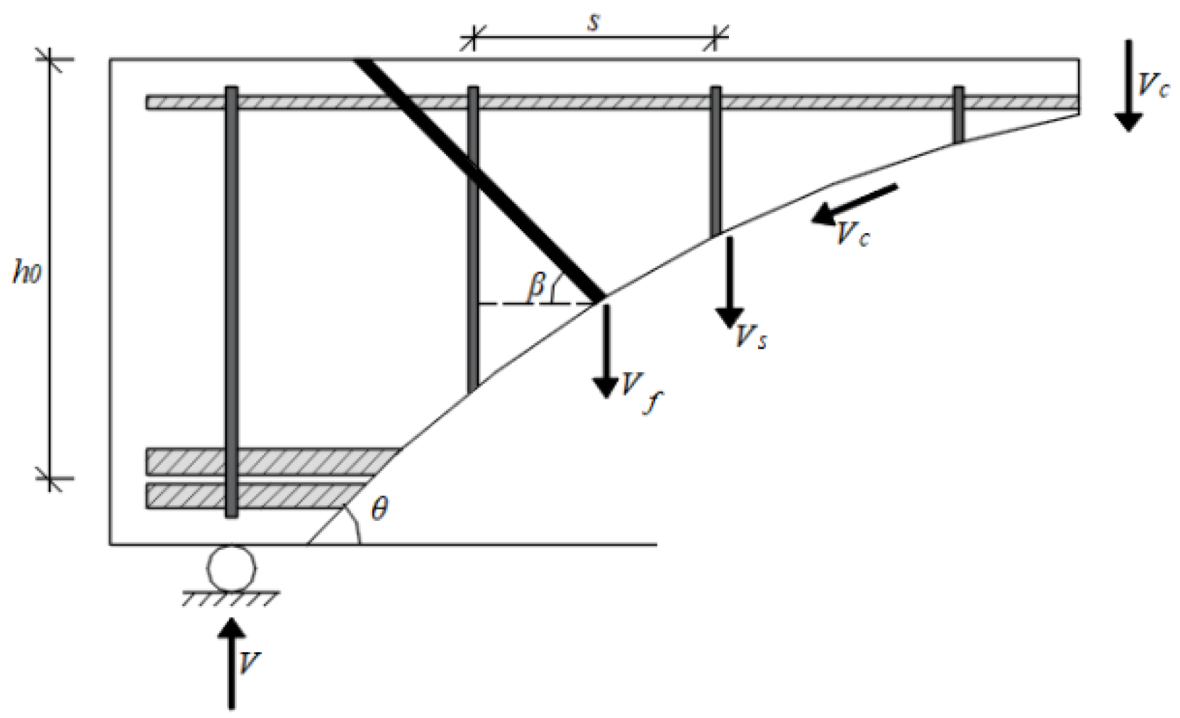
The truss–arch model [
29] is commonly used to predict the shear capacities for reinforced concrete beams. Since the load-bearing capacity provided by externally unbonded CFRP is not constrained by the concrete beam, a separate calculation is often employed. As shown in
Figure 11, the shear capacity of the oblique section in the strengthened concrete beam can be expressed as the sum of the capacities of the concrete, the stirrups, and the CFRP tendons:
where
is the shear strength at the beam yield;
is the shear strength provided by the concrete;
is the shear strength provided by the stirrups;
is the shear strength provided by the CFRP tendons.
4.1. Initial Beam
The shear strength of the original beam comprises the strength of the concrete (
) and the stirrups (
). These values can be calculated by referencing existing standards. This study refers to the Chinese standard GB50010-2010, entitled “Code for Design of Concrete Structures” [
30]. The equation employed for shear capacity is as follows:
where
is the concrete shear capacity factor, which is valued by Equation (3);
is the shear span ratio;
is the tensile strength of concrete;
and
are the width and effective depth of the concrete beam, respectively;
is the total cross-sectional area of all stirrup legs in the oblique section;
is the yield strength of stirrups;
is the stirrup spacing;
is the angle of the diagonal cracks.
4.2. Reinforcement of CFRP Tendon
The axial force of the CFRP tendons is transmitted to the reinforced concrete beam through reaction steel plates. When the reaction steel plates are stably and firmly fixed to the reinforced concrete beams, the contribution to the shear strength of the CFRP tendons is as follows:
where
is the number of CFRP tendons that are projected through diagonal cracks in the shear span;
is the effective stress of the CFRP tendons;
is the area of a single CFRP tendon.
The effective stress of CFRP tendons can be determined as the sum of the prestress and the stress increment. The stress increment can be calculated by the strain increment:
where
is the prestress of the CFRP tendons;
is the stress increment of the CFRP tendons;
is the elastic modulus of the CFRP tendons;
is the strain increment of the CFRP tendons.
The deformation of the CFRP tendon in the strengthened beam equals the relative displacement between the two reaction steel plates of the CFRP tendon. To determine the vertical displacement of the two reaction steel plates, it is necessary to calculate the shear deformation of the beam. The model depicted in
Figure 12 is constructed based on the shear deformation computation approach presented by Pan et al. [
31]. The deformation of the CFRP tendons is represented as the relative deformation between the anchoring ends A and B of the CFRP tendons after loading:
where
and
are the vertical deformations at the anchoring ends A and B of the CFRP tendons, respectively.
The vertical deformation of the truss was induced by the compression of the inclined concrete struts and the elongation of the stirrups. The length of the oblique concrete column is
, and the width is
. Under the action of the shear force, the vertical deformations of the concrete and the stirrups in the shear zone are expressed as follows:
where
and
are the vertical deformation values induced by the inclined concrete struts and stirrups, respectively;
is the shortening of the inclined concrete struts;
is the compressive strain of the inclined concrete struts;
and
are the elastic modulus values of the concrete and stirrups, respectively;
is the shear force acting on the beam.
After reinforcement, the stirrups and CFRP tendons collaborate to establish the overall stiffness. When calculating the overall stiffness, it is essential to unify the two materials into a common material. This involves transforming the CFRP tendons into equivalent-area stirrups. Prestressing enables the CFRP tendons to reserve shear force, consequently mitigating the deformation of the stirrups. The shear deformation caused by the stirrups in the beam with CFRP tendons is expressed as follows:
where
is the vertical deformation caused by the stirrups after reinforcement; is the stirrup ratio;
is the equivalent conversion coefficient for transforming CFRP tendons into stirrups, representing the ratio of their elastic modulus;
is the elastic modulus of the CFRP tendons.
The vertical deformation is proportional to the distance from the bearing chair in the shear zone in the model. The vertical displacement at the restrained end of the CFRP tendon can be determined and then substituted into Equation (8):
where
and
are the horizontal distances from the bearing chair to the anchoring ends A and B, respectively;
is the length of the shear zone.
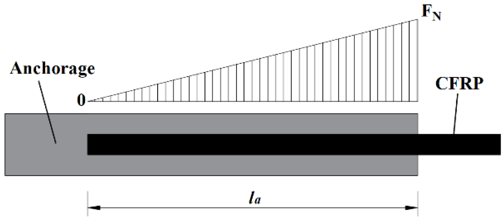
The fixation of a CFRP tendon in this reinforcement method requires coordination with two anchorages, and the CFRP tendon is secured to the anchorages by friction. Referring to the internal force of the CFRP tendon in the anchorages proposed by Ping [
32], as shown in
Figure 13, the axial elongation length of the CFRP tendon in the anchorages under the action of the axial tensile force is given by the following equation:
where
is the axial elongation length of the CFRP tendon in the anchorage section;
is the length of the CFRP tendon in the anchorage section;
is the axial tension force of the CFRP tendons. Thus, the calculated length of the CFRP tendon in the anchorage section is 1/2
. The calculated length of the CFRP tendon (
) and the strain increment of the CFRP tendon (
) are given by the following equations:
4.3. Calculation of Shear Capacity
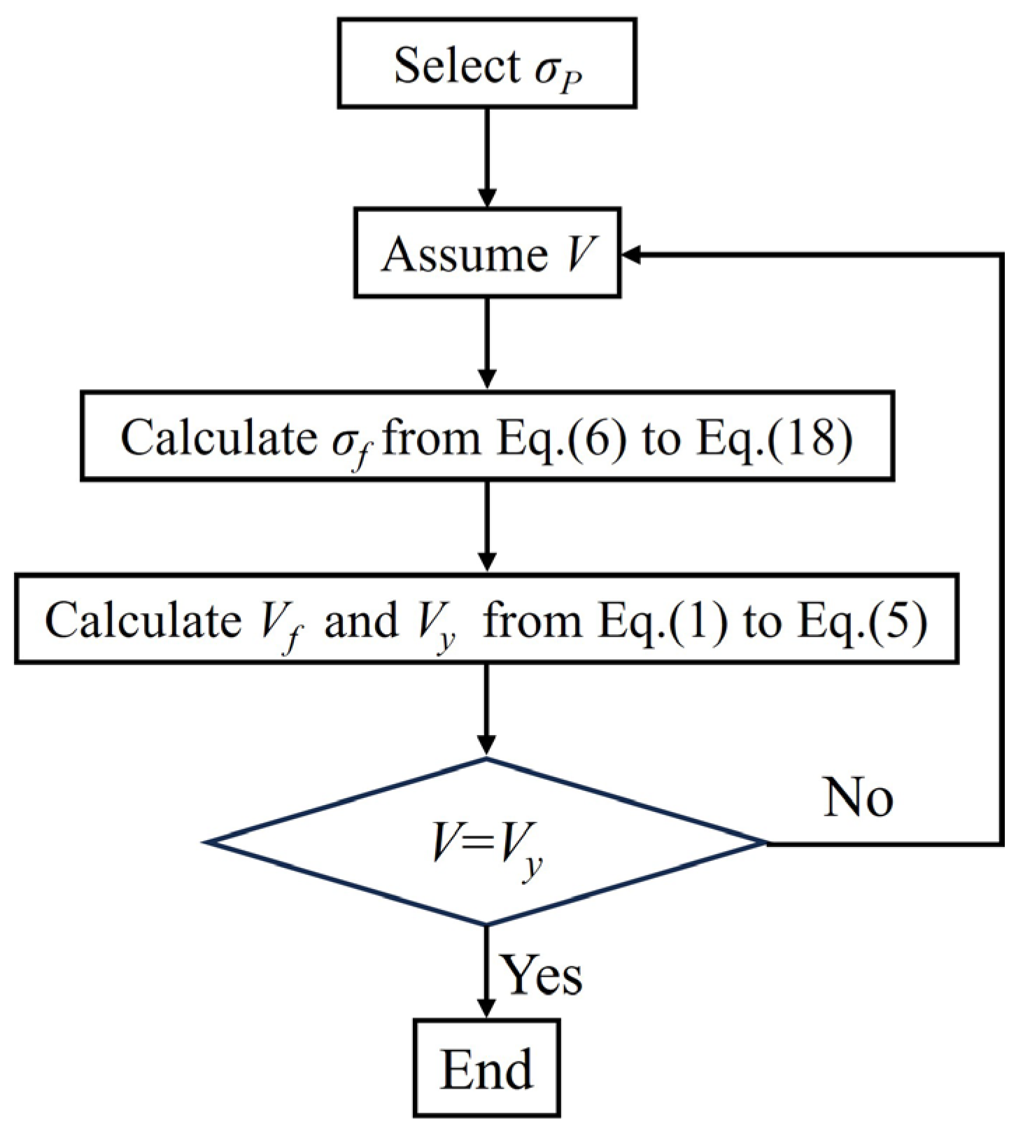
When calculating the shear capacity, under the action of the initial shear force, shear deformation occurs in the beam, leading to an increase in the stress of the CFRP tendons. This increases the contribution of the CFRP tendons, resulting in an elevated shear capacity of the beam. To predict the shear strength of a beam reinforced with externally unbonded prestressed CFRP tendons, it is necessary to execute an iterative program, as depicted in
Figure 14. The shear capacity is deemed to have reached the limit of yielding when further iterations do not yield an increase in shear capacity.
In engineering, the prestress level of CFRP tendons generally does not exceed 50% of their tensile strength, commonly less than 1000 MPa [
33]. When the inclination angle is 45°, after iterative calculations, the maximum effective stress of the CFRP tendon under the test conditions in this study was determined to be 1421 MPa. Therefore, the tension in the CFRP tendons typically remained below their maximum tensile strength, and fracture did not occur. The iterative calculations did not account for the fracture of the CFRP tendons. The discrepancies between the predicted results and the experimental results are within 10%, as shown in
Table 6 for comparison.
5. Conclusions
This article introduces a methodology for improving the shear performance of reinforced concrete beams by employing externally unbonded prestressed CFRP tendons. Through comparative model experiments, we explored the influence of prestressed CFRP tendon reinforcement on the shear capacities, failure modes, and the developments of diagonal cracks in concrete beams. The mechanism of this reinforcement method was analyzed, leading to the following conclusions:
The CFRP tendons operated collaboratively with the stirrups after the occurrence of diagonal cracks, thereby diminishing the strain on the stirrups and delaying their yield. After the stirrups yielded, the CFRP tendons assumed the heightened shear force, enhancing the ultimate shear capacity and the ductility of the beams. Prestressing enhanced the efficacy of the CFRP tendons, with a higher prestress resulting in better reinforcement effects. In the experiment, the increment in the yield load was minimal in the absence of prestress, registering a growth rate of 28%. The most substantial increase was observed at 800 MPa of prestress, attaining a growth rate of 70%. Similarly, the increase in the ultimate load was minimal without prestress, exhibiting a growth rate of 47% and peaking at 800 MPa of prestress, registering a growth rate of 87%.
The initial damage within the shear zone diminished the early shear stiffness and augmented the early widths of diagonal cracks, with this effect gradually diminishing as the applied load increased. The initial damage within the shear span region demonstrated no significant impact on the shear capacity.
The CFRP tendons, as shear reinforcement, significantly increased the cracking load, delayed the initiation of diagonal cracks, and restricted the development of crack widths. In the experiments, the cracking load of the reinforced beams increased with higher levels of prestress. Furthermore, under the same loading conditions, specimens with higher prestress in the CFRP tendons exhibited smaller diagonal crack widths. Prestress provided a reserve of shear capacity, with higher prestress resulting in higher cracking loads and smaller crack widths.
External unbonded prestressed CFRP tendon reinforcement can fully utilize the tensile strength of the CFRP tendons. Without prestress, the CFRP tendons could exhibit only 47% of their strength. However, with prestress, the CFRP tendons could exhibit at least 68% of their strength, resulting in a more significant improvement under ultimate loads compared to instances without prestress.
The deformation of the CFRP tendon in the reinforced beam was equal to the relative displacement between the two reaction steel plates and was directly affected by shear deformation of the beam. Based on this connection, a calculation method for externally unbonded prestressed CFRP tendon reinforcement for the shear capacity of concrete beams is proposed. The predicted results show an error of less than 10% when compared to the experimental results, providing a relatively accurate prediction of the shear capacity.
The above conclusions will be substantiated through additional testing and finite element simulations to enhance the reliability of the test results and attain sufficient design values, considering a broader range of variability. However, further experimental work and theoretical research are required to establish more rational and accurate predictive models, encompassing various concrete strengths, stirrup spacing, and types of FRP.


