Article

Strengthening of Laminated Veneer Lumber Slabs with Fiber-Reinforced Polymer Sheets—Preliminary Study

by
Michał Marcin Bakalarz
and
Paweł Grzegorz Kossakowski
*
Department of Theory of Structures and Building Information Modeling, Faculty of Civil Engineering and Architecture, Kielce University of Technology, Al. Tysiaclecia Panstwa Polskiego 7, 25-314 Kielce, Poland
*
Author to whom correspondence should be addressed.
Fibers 2024, 12(3), 22; https://doi.org/10.3390/fib12030022
Submission received: 18 December 2023 / Revised: 15 January 2024 / Accepted: 19 February 2024 / Published: 28 February 2024
(This article belongs to the Collection Feature Papers in Fibers)

Abstract

:
Analyzing the feasibility of reinforcing new and existing wooden structures is a valid problem, being the subject of numerous scientific papers. The paper presents the preliminary results of a study on reinforcing Laminated Veneer Lumber (LVL) panels with composite materials bonded to exterior surfaces using epoxy resin. Glass-Fiber-Reinforced Polymer (GFRP) sheets, Carbon-Fiber-Reinforced Polymer (CFRP) sheets, and Ultra-High-Modulus (UHM) CFRP sheets were used as reinforcement. The variables in the analysis were the type of reinforcement and the number of reinforcement layers. The tests were carried out on small samples (45 × 45 × 900 mm) subjected to the so-called four-point bending test. Reinforcement positively affected the mechanical properties of composite section. The highest increases in load bearing were 37 and 48% for two layers of GFRP and CFRP, respectively. The bending stiffness increased up to 53 and 62% for two layers of CFRP and UHM CFRP, respectively. There was a change in failure mode from cracking in the tension zone for unreinforced beams to veneer shear in the support zone (for CFRP and GFRP sheets) and sheet rupture (UHM CFRP). Good agreement was obtained for estimating bending stiffness with the presented numerical and mathematical model; the relative error was up to 6% for CFRP and GFRP and up to 20% for UHM CFRP. This preliminary study proved the effectiveness of combining LVL with FRP sheets and indicated their weak spots, which should be further analyzed to improve their competitiveness against the traditional structures. The key limitation was the shear strength of LVL.

1. Introduction

The reinforcement of wooden and wood-based elements has been the subject of numerous scientific papers [1,2,3]. These have concerned both new [4] and existing elements [5,6]. Traditional materials made of steel or aluminum have been used as reinforcement. Currently, due to their numerous advantages such as low weight, high tensile strength, and rigidity or durability, composite materials reinforced with carbon [7], glass [8], aramid [9], and basalt [10] fibers are used, with the use of natural fibers being less frequent.
The positive effect on the physical and mechanical properties of composite reinforcement on strengthened wooden-based structural elements is well known. This effect depends on the properties, location, and method of combination of FRP materials with wood. Among others, the most significant environmental and economic benefits are the following: the possibility to preserve the historical elements by increasing their load-bearing capacity [11]; increasing the life of an existing structure [12]; enabling the utilization of faster-growing wood species or low-grade elements [13]; applying smaller cross-section sizes, and therefore lowering material consumption and increasing the net area of spaces; removing the cost required to replace timber elements with new ones when modifying existing building [5]; and the reduction in the variability of the mechanical properties of wooden elements.
Among the negative aspects, the biggest disadvantage of composite materials is their high cost. Several measures can be implemented to minimalize it. Instead of applying reinforcement along the entire surface, it is possible to limit its scope to local damage, the impact of which depends on its geometry and location [14]. Burawska et al. [15] proved the application of a D-shaped CFRP strip to strengthen a solid timber beam with a defect simulated by pre-drilled holes. De Jesus [16] et al. concluded no significant influence of the length of reinforcement on bending stiffness when analyzing solid timber beams strengthened with CFRP laminates of distinct lengths. Moreover, the reinforcement ratio can vary along the element length. Various connection methods can be utilized like mechanical, adhesive, or mechano-adhesive measures. Choosing the appropriate method at the design stage could be beneficial and allow the reuse of timber and FRP elements in future—for example, for mechanical connection only. Finally, due to the vast diversity of composite materials, the most economic and effective fibers can be chosen or combined with each other. For example, Xian et al. [17] studied the possibility of reducing the material cost through the combination of GFRP and CFRP materials. It should be pointed out that when analyzing the cost of reinforcement, not only the cost of FRP but also other factors like the required time, space, and equipment for application of reinforcement should be considered. Dewey et al. [18] presented an FRP-based method to rehabilitate and repair timber bridge girders and concluded that this method is quick and economical.
Other crucial aspect is the long-term performance of composite material. The deterioration of tensile strength in the function of temperature, exposure days, and the cross-section size of basalt Fiber-Reinforced Polymer BFRP and GFRP rods exposed to an alkaline environment was reported by Kim and Oh [19]. The most important factor was temperature. An experimental study on the fatigue resistance of CFRP cables was presented in [20], obtaining good results and possibilities for further development.
Nunez-Decap et al. [21] investigated the possibility of using carbon and basalt composites to improve the physical and mechanical properties of LVL panels glued in at the manufacturing stage. An increase in tensile strength and hardness was obtained compared to unreinforced elements. Sokolovic et al. [22] used carbon fabric as reinforcement for LVL beams in their paper. As in the previous paper, reinforcement was applied at the manufacturing stage, and the result was an improvement in load-bearing capacity and flexural rigidity. Kossakowski and Sokołowski [23] investigated the possibility of using PBO meshes to reinforce solid beams, achieving a significant increase in the load-bearing capacity and ductility of the system with a slight increase in rigidity. Rescalvo et al. [24] presented the results of an experimental study on the properties of LVL beams reinforced with basalt and carbon composites. Subhani et al. [25] developed an analytical model to account for the non-linear expansion and contraction of compressive wood for LVL beams reinforced with CFRP composites. Ball [26] studied the joint, delamination, and flexural properties of fiberglass-reinforced LVL beams. The mechanical and physical properties of wood–glass and wood–jute–glass hybrid laminates are described in [27]. The first configuration proved to be more favorable.
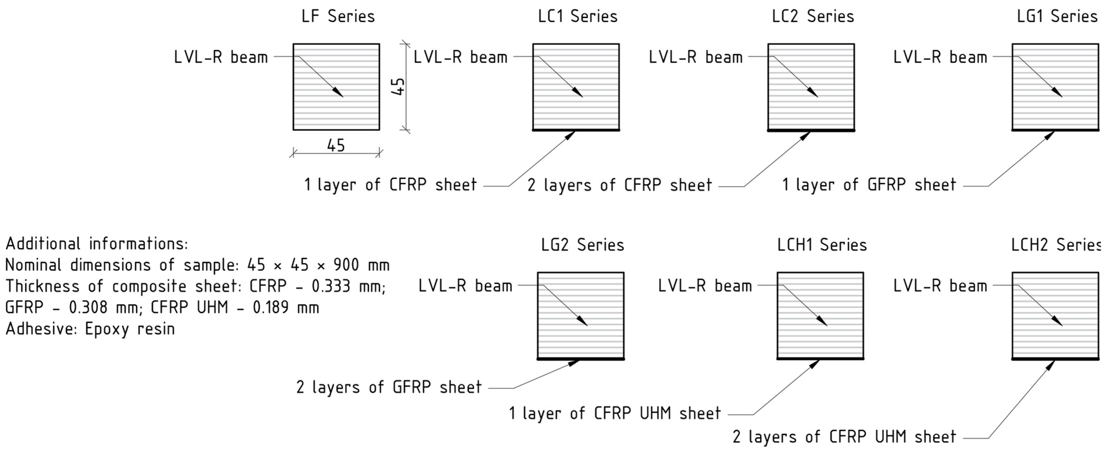
In this paper, a preliminary analysis is presented on the reinforcement of panel elements made of laminated veneer lumber. The main objective of the experimental research was to verify the validity of using glass and carbon sheets as reinforcement for LVL panels. Three types of sheets, varying in both mechanical and physical properties as well as price, and two reinforcement thicknesses were analyzed for each type. The discussion section presents the results of applying a mathematical and numerical model to predict the stiffness and flexural capacity of unreinforced and reinforced elements. The described composite cross-sections have better mechanical properties, which may translate into an increase in their competitiveness against steel or concrete elements.
Laminated veneer lumber is a relatively new engineering wood product. Due to the removal of typical wood flaws such as knots at the production stage, it is characterized by higher and more stable mechanical properties than solid timber. Elements made out of LVL can be used as beams (purlin, rafters) or slabs. Experimental and numerical analyses of LVL slabs as single elements or being parts of composite steel–LVL sections were presented in [28,29].

2. Materials and Methods

2.1. Materials

2.1.1. Laminated Veneer Lumber (LVL)

The research was carried out on perpendicular laminated veneer lumber panel samples in a so-called flatwise condition, meaning that the load was applied to the veneer surface, perpendicular to the layer layout. Samples were cut out from 200 mm wide LVL panel bought from Steico (Czarnków, Poland). Each sample consisted of 15 layers of pine veneers, each approx. 3 mm thick. The cross-section of the beams was 45 × 45 mm. The total length of the beams was 900 mm. Prior to the experimental test, the samples were stored in laboratory hall. Selected physical and mechanical properties of the LVL, as determined through our own experimental research, are shown in Table 1. This research was conducted according to standards [30,31] and is discussed in papers [32,33]. The moisture content value of LVL was measured after bending tests with Tanel WRD-100 electrofusion moisture meter; average value is presented in Table 1. The size of LVL is a resultant of economic factors and preliminary character of research considering the standard requirements.
Samples after experimental tests are shown in Figure 1.

2.1.2. Fiber-Reinforced Polymer (FRP) Sheets

Two types of unidirectionally reinforced carbon-fiber-reinforced polymer (CFRP) sheet were used to reinforce the beams: high-strength CFRP and UHM CFRP, as well as one type of bi-directional glass-fiber-reinforced polymer (GFRP) sheet. Composite materials had been manufactured by S&P Reinforcement Polska (Malbork, Poland). In the case of carbon sheets, fibers running in the main direction (black color) were stabilized by transverse polyester fibers (white color). The glass sheet had 90% of the fibers arranged in the main direction and 10% in the transverse direction. The sheets were laid out in such a way that the main direction of the sheets was parallel to the wood fibers in successive veneer layers. Selected physical and mechanical properties are presented in Table 2.
Figure 2 presents a view of the composite materials. The carbon sheets were delivered in 30 cm wide rolls and the glass sheet in a 90 cm wide roll. The reinforcement was cut to the correct dimensions with scissors.

2.1.3. Epoxy Resin

S&P Resin 55 HP two-component epoxy resin was used to bond the composite to the LVL panel. Glue was applied to both the sheet and the veneer surface and spread using a rubber spatula. When bonding two sheet layers, a thin layer of quartz sand was applied between the layers. This treatment was aimed at improving the bond between them. The adhesive consumption was approx. 1 kg of mixture per 1 m2 of glued surface. Selected properties of the adhesive are presented in Table 3. These parameters were evaluated according to [38,39].

2.2. Methods

The tests were carried out in accordance with European standards [30,31] by means of a four-point bending test. The purpose of the study was to determine the effectiveness of using selected composite materials to reinforce LVL panels. The scope of the analysis included preparation and testing of following series:
  • LF—unreinforced beams;
  • LC1—beams reinforced with one layer of CFRP sheet bonded to bottom surface;
  • LC2—beams reinforced with two layers of CFRP sheet bonded to bottom surface;
  • LCH1—beams reinforced with one layer of UHM CFRP sheet bonded to bottom surface;
  • LCH2—beams reinforced with two layers of UHM CFRP sheet bonded to bottom surface;
  • LG1—beams reinforced with one layer of GFRP sheet bonded to bottom surface;
  • LG2—beams reinforced with two layers of GFRP sheet bonded to bottom surface.
A total of 10 unreinforced beams and 30 reinforced beams were tested (each series contained 5 elements). The reinforcement configurations are shown in Figure 3.
The static diagram of the beam is shown in Figure 4. The total span of the specimens was 900 mm, which was equal to 20 times the height of the cross-section. The support spacing was 800 mm. The distance between the axis of the support and the axis of application of the concentrated force was 265 mm. The distance between the concentrated forces was equal to 6 times the height of the cross-section, i.e., 270 mm.
View of the test bench is shown in Figure 5.
The tests were conducted at the material strength laboratory of Kielce University of Technology using the MTS-322 hydraulic testing machine with the load cell capacity being equal to 100 kN. The specimens were loaded symmetrically with two concentrated forces; a steel I-beam was used to distribute the load. The load was controlled by the movement speed of the hydraulic actuator, which was assumed as 3.5 mm/min. Bending was carried out until the element was completely destroyed. During the tests, the loading force F, test duration t, actuator displacement, and deflection at the center of the beam span u were measured.

3. Results and Discussion

The static behavior of unreinforced and reinforced elements is presented by means of an analysis of bending strength, bending stiffness, and failure mode. The application of numerical analysis and a simple mathematical model to estimate bending stiffness and load-carrying capacity was verified.

3.1. Load-Bearing Capacity

Figure 6 and Figure 7 present charts of the load deflection relationship of the beam at mid-span for all the elements tested. Unreinforced beams tended to exhibit linear behavior with slight deviations in the curve at the end of the test. Similar behavior was observed for the bending of unreinforced LVL in the edgewise condition [9] and solid timber beams [41] with a relatively small cross-section height (up to 10 cm). This non-linearity, however, was not present when testing full-size (with the height of the cross-section being equal to 20 cm) LVL beams in an edgewise condition [32], where perfectly linear behavior was observed.
The beams reinforced with CFRP and GFRP sheets behaved similarly—in the figure, a linear part in the initial phase of the test is visible, followed by plasticization. The destruction of these elements is usually caused by a single crack in LVL. Beams reinforced with CFRP UHM sheets failed by repeatedly cracking in increments. In the case of the LCH1 series beams, the first decrease in the load force value was due to a break in the continuity of the UHM CFRP sheet while the next was the result of LVL failure. The destruction of the wood occurred at a similar load value to that of the reference beams; thus, there were no significant changes in load-bearing capacity for this series. It should be noted that the second drop occurred with a higher loading force value when compared to the first one (an increasing trend). Similar stepped-like curves were observed for the LCH2 series. The difference was that the first cracking, resulting from the rupture of the sheet, was accompanied by minor damage of adjacent veneers. This phenomenon can be explained by a higher reinforcement ratio, which provided higher tensile strength in the composite and therefore a higher load-carrying capacity in the specimen. Because of the damaging of the LVL at the first crack, the second drop occurred at a lower loading force (a decreasing trend).
The increased utilization of compressive strength of solid timber, glue-laminated timber, or laminated veneer lumber elements strengthened with FRP, as well as stepped-like failure for beams strengthened with FRP with low elongation at rupture, is expected behavior and has been reported in previous studies [7,9].
The values of the maximum loading force and corresponding bending moment and deflection at mid-span for the tested beams, as well as their mean values (MVs) and standard deviations (SDs) for each series, are shown in Table 4, Table 5, Table 6, Table 7, Table 8, Table 9 and Table 10. They also include information on the failure mode of each element, which is described later in the article.
Figure 8 shows the average values of the maximum loading force and the corresponding deflection of the beam at the center of the span. The largest load-carrying capacity gains were recorded for beams reinforced with CFRP sheets, amounting to 37% and 48% for one and two layers of reinforcement, respectively. The smallest increments were recorded for elements reinforced with UHM sheets. The use of a glass sheet proved to be an intermediate solution. As the degree of reinforcement of the cross-section increased, accompanied by an increase in the bending stiffness of the beam, the deflection of the beam at which failure occurred decreased.

3.2. Bending Stiffness

The bending stiffness k of the beams was estimated based on the relationship occurring between the force increments F and the corresponding deflection increments at the center of the span u of the beam according to the below formula [42]:
k = F/u,
where F is the loading force and u is the mid-span deflection.
Figure 9 presents curves showing changes in the bending stiffness of bent elements concerning the deflection increase in the middle of the span for selected elements from each tested series. It should be noted that in each case, there was a slow degradation of stiffness over the course of the test until the beam failed. At the moment of failure, there was a sharp decrease in rigidity. Only in the case of beams reinforced with UHM CFRP sheets were there two such decreases: the first was due to the sheet cracking and the second was due to the veneer cracking in the tension zone.
Figure 10 shows the average bending stiffness values for each series. The estimated average values were in the range of 0.1–0.4 of the maximum force. The largest increase in rigidity was recorded for beams reinforced with two carbon sheet layers, amounting to 53% and 62% for the LC2 and LCH2 series, respectively. The smallest increase in rigidity characterized the LG1 and LG2 series beams of 11% and 22% for one and two reinforcement layers, respectively. The increase in the bending stiffness of a beam depends on the value of the elastic modulus of the composite material.
The graduate loss of bending stiffness with an increasing load is expected behavior and was described in previous papers for LVL and timber beams strengthened with FRP sheets [7,32,33,42]. Similarly, the increase in bending stiffness depends on the product of the modulus of elasticity of FRP, reinforcement ratio, and location of reinforcement [42]. Generally, the higher the reinforcement ratio and modulus of elasticity of FRP are, the higher is the increase that is obtained. When compared to the edgewise condition [7], a similar increase in bending stiffness was obtained for beams strengthened with aramid-fiber-reinforced polymer AFRP and GFRP sheet, being equal to approx. 10% for one layer of reinforcement. Raftery et al. [10] concluded a 10% enhancement of stiffness for timber beams strengthened with basalt rods with a 1.4% reinforcement ratio. From the point of view of the location of reinforcement, the most effective solution is the configuration wherein the reinforcement is placed on an external compressed and tensile face of the beam [43]; the average increases were 86% and 182% for one and two layers of CFRP, respectively. A slightly less effective solution is positioning the reinforcement on the sides of the beam.

3.3. Failure Modes

Generally, the failure modes can be classified into one of the three main types. The typical failure of unreinforced beams was by rapid cracking, caused by exceeding the tensile strength in the zone of maximum bending moment fm. Beams reinforced with UHM sheets failed due to sheet breakage (reaching the elongation at rupture εf of FRP) and following veneer cracking (similarly to the unreinforced specimen). This was related to the low value of elongation at rupture of the reinforcement compared to other analyzed materials and the flatwise orientation of veneers. Beams reinforced with CFRP and GFRP sheets tended to fail by shearing between layers of veneer by exceeding the shear strength of LVL parallel to the grain fv,k. Failure examples are shown in Figure 11.
The tension failure of unreinforced beams made out of timber or engineering wood products with relatively low moisture contents was reported by many scientists [2]. The shear failure mode is typical for slab-like LVL elements strengthened with FRP materials [43]. The rupture of UHM CFRP sheets, due to their low elongation-at-rupture value, was reported in several tests [7] when applied to the tensile face of a beam. In contrast, materials characterized by high elongation at rupture, like CFRP and GFRP, are more likely to withstand higher deflection values [8]. For example, solid timber beams with low cross-section heights strengthened with GFRP and CFRP sheets [41] failed at deflections equal to 232% and 252% of the unstrengthened beam deflection, respectively.

3.4. Numerical Analysis

The numerical model of unreinforced and reinforced LVL beams was prepared in Abaqus 2017. Guidelines and assumptions for creating such models are included in publications [44,45]. Only our model’s most important assumptions are presented in this paper.
The laminated veneer lumber was modeled as a three-dimensional deformable body, the supports as discrete rigid shell elements, and the composite material as three-dimensional shell elements. A reference point added to the midpoint of the upper surface of the support was used to control boundary conditions and loading. In the initial phase, only rotation against the X-axis was available for supports. Assembly consisted of six parts, including the LVL, FRP, and four supports. A view of the assembled model and meshing is shown in Figure 12. The connection between the LVL and the composite material was made using tie constraints, thus neglecting the influence of the adhesive layer in the analysis; this was because no debonding was recorded and the adhesive layer was very thin and could not be distinguished with the naked eye on the cross-section. Contact between parts was modelled using surface-to-surface contact interaction with a “Hard” Contact normal behavior and a 0.2 friction coefficient for tangential behavior. Loading was accomplished by means of displacement of the loading thrust by applying 20 mm displacement along the U2 direction in the loading phase. The calculations were performed in the static range. A linear perfectly plastic material model was used to describe the behavior of veneer and composite materials as linear (according to Table 1 and Table 2). An approximate global finite element size of 5 mm was adopted. The following types of finite elements were used: beam—C3D8R, reinforcement—S4R, and supports—R3D4.
The validity of using this model to estimate bending stiffness was verified. The numerical model accurately describes the behavior of the elements in the initial phase of the test, with larger differences occurring in the final phase. The difference between the experimental and numerical bending stiffness values was no greater than 20% for the LCH1 series and 6% for other configurations. Examples of curves obtained from the numerical model against experimental results for unreinforced and reinforced beams are shown in Figure 13. Curves plotted with the red color were obtained from numerical analysis; curves plotted with the black color were from experimental tests.
The obtained results are within the expected deviation when compared to the similar research regarding strengthening timber elements with FRP materials; for example, a 10% relative error was obtained when applying such a model for an LVL CFRP sandwich structure [43]. It should be pointed out that after the initial phase, due to the degradation of bending stiffness, the non-linear behavior of real-life elements occurs faster than in the simulation. This phenomenon is starting in the simulation when reaching stress values corresponding to the yield point. The presented model is not able to capture the failure mechanism correctly, and therefore, this part was omitted from the discussion.

3.5. Mathematical Model

The theoretical analysis was carried out using a simple mathematical model based on equivalent cross-sectional characteristics, which has been described in detail in papers [46,47,48,49,50]. In this model, the composite material is taken into account by proportionally increasing the cross-sectional dimensions of the veneer. The proportionality factor was determined by the below formula:
n = E FRP / E LVL ,
where EFRP is the modulus of elasticity of FRP and ELVL is the modulus of elasticity of LVL.
The second moment of inertia of the transformed cross-section was evaluated according to the below formula:
I y = i = 1 n I yi + A i · z i 2 ,
where Iyi is the second moment of inertia of the elemental field, Ai is the cross-section area of the elemental field, and zi is the distance between the geometric centroid of the elemental field and the assumed position of the horizontal axis.
The maximum bending moment M, assuming linear stress distribution along the depth of the cross-section, was evaluated according to the below formula:
f m = M · z I y   M = f m · I y z ,
where fm is the bending strength of LVL, z is the distance between the geometric centroid and external fibers and Iy is the second moment of inertia of the transformed cross-section.
A view of the transformed cross-section is shown in Figure 14.
The mathematical analysis results are shown in Figure 15. A good agreement was obtained between the experimental and theoretical values of bending stiffness for unreinforced and reinforced beams. The relative error was equal to 6% for GFRP and CFRP strengthened samples and 20% for samples with UHM CFRP. Larger discrepancies were obtained for flexural capacity. This was due to the fact that the model used does not take into account the possibility of failure other than bending and the effect of the limit elongation of the composite material and assumes a linear distribution of stresses over the height of the cross-section. In the case of UHM CFRP sheets, due to their low value of elongation at the moment of failure, this model is not suitable for estimating the maximum bending moment. Instead, it is necessary to introduce an equation based on the curvature of the beam and then, based on it, determine the deflection at which the sheet breaks. After that break, the beam will behave as an unreinforced element. Similarly, large discrepancies between experimental and theoretical values were found when failure occurred due to veneer shearing.
The transformed cross-section method was proven to be an effective solution for the evaluation of bending stiffness in timber beams reinforced with FRP materials. Similar differences between experimental and theoretical bending stiffness values, up to 7%, were obtained in [46] for full-scale LVL beams strengthened with various CFRP composites. An analogical conclusion can be drawn for LVL CFRP sandwich structures [43]. However, it should not be used to evaluate the load-bearing capacity when the shear failure may occur [43], for using an FRP with low elongation at rupture, or when the reinforcement ratio is high [51].

4. Conclusions

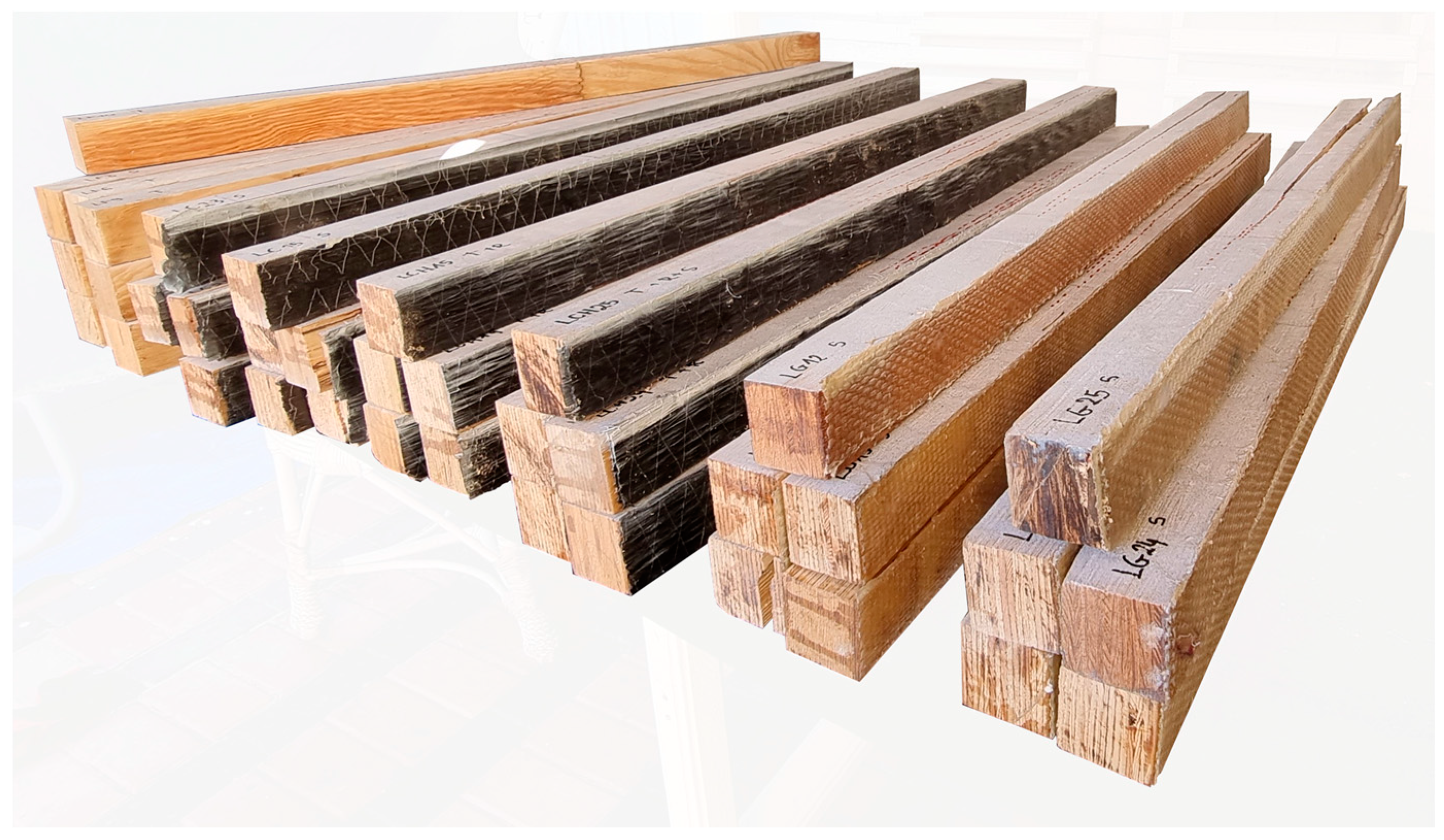
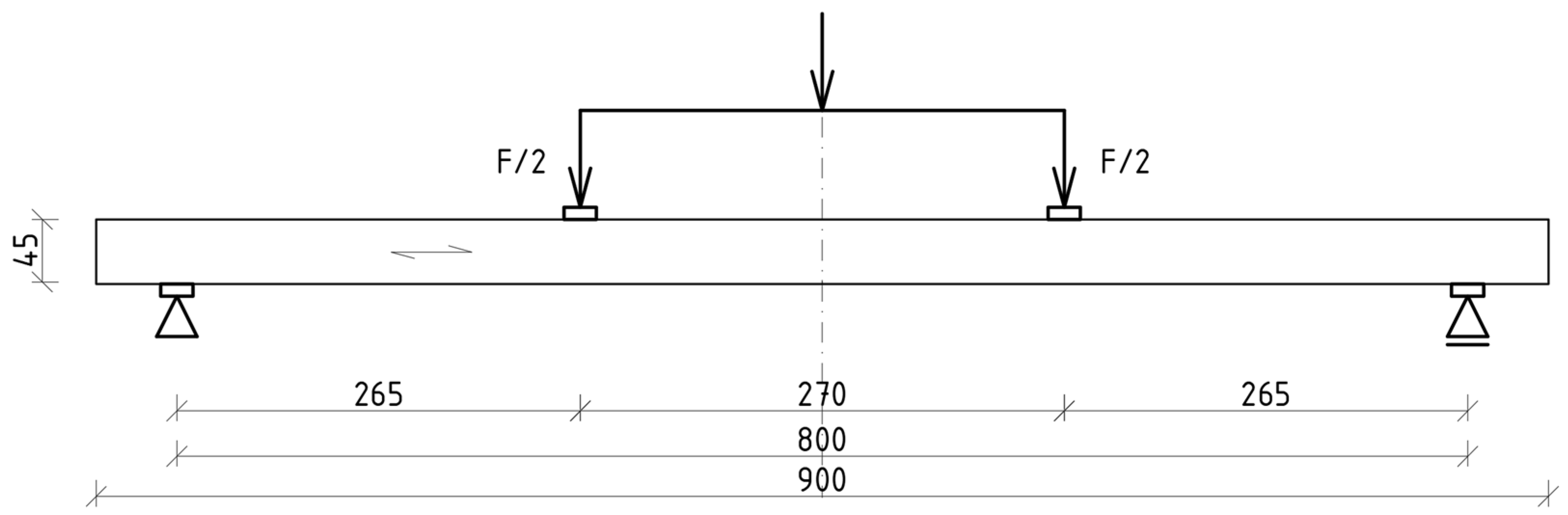
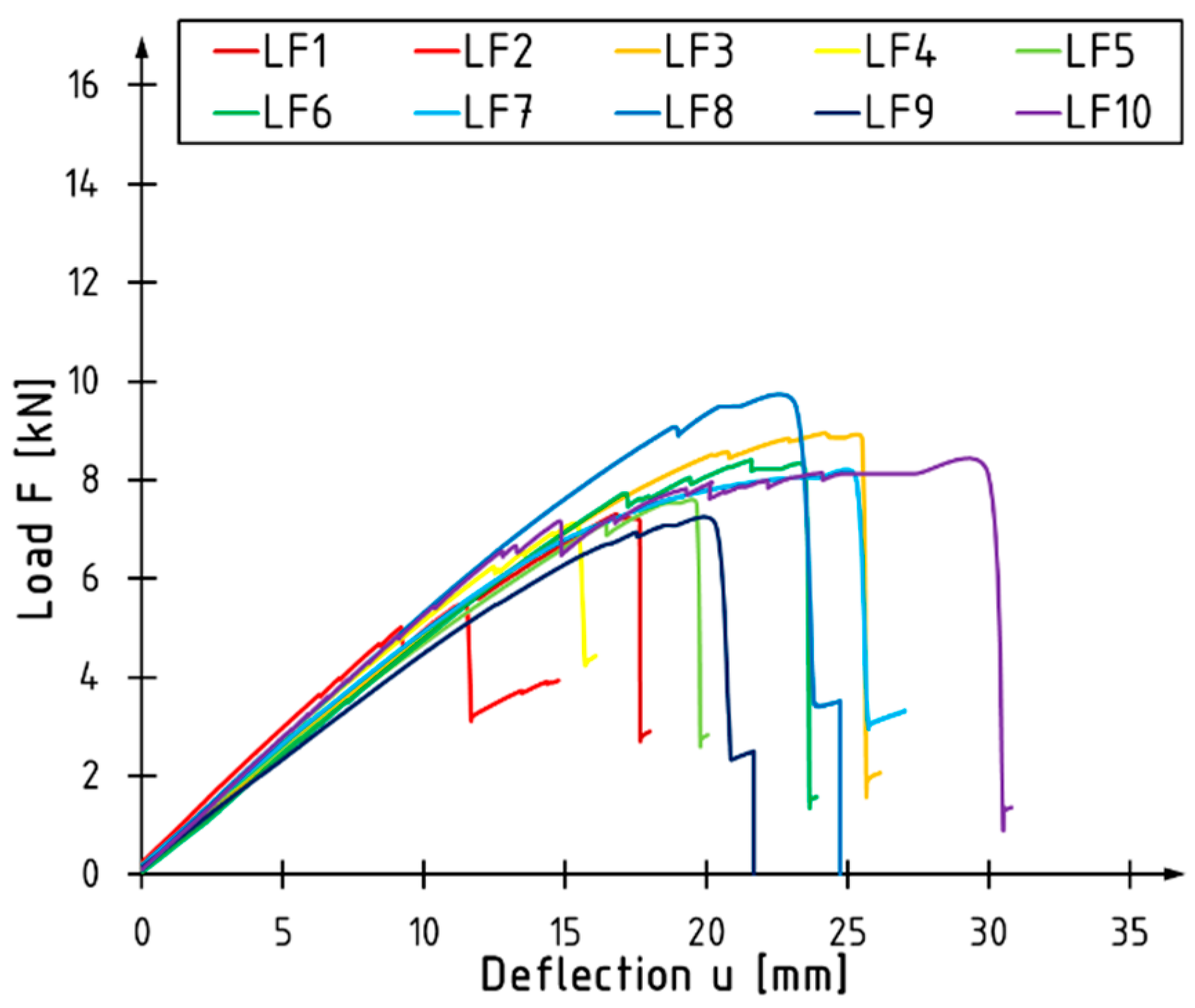
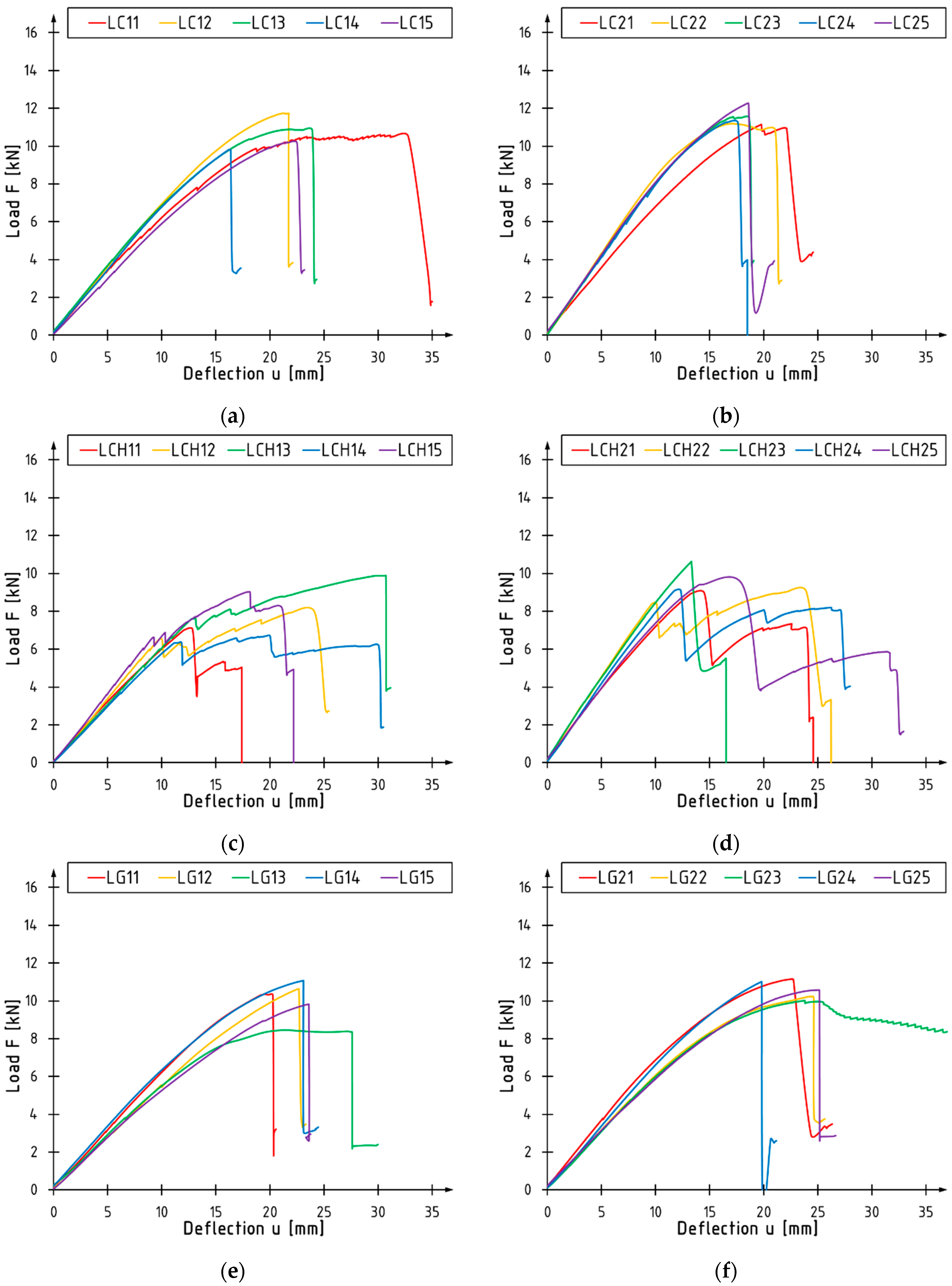
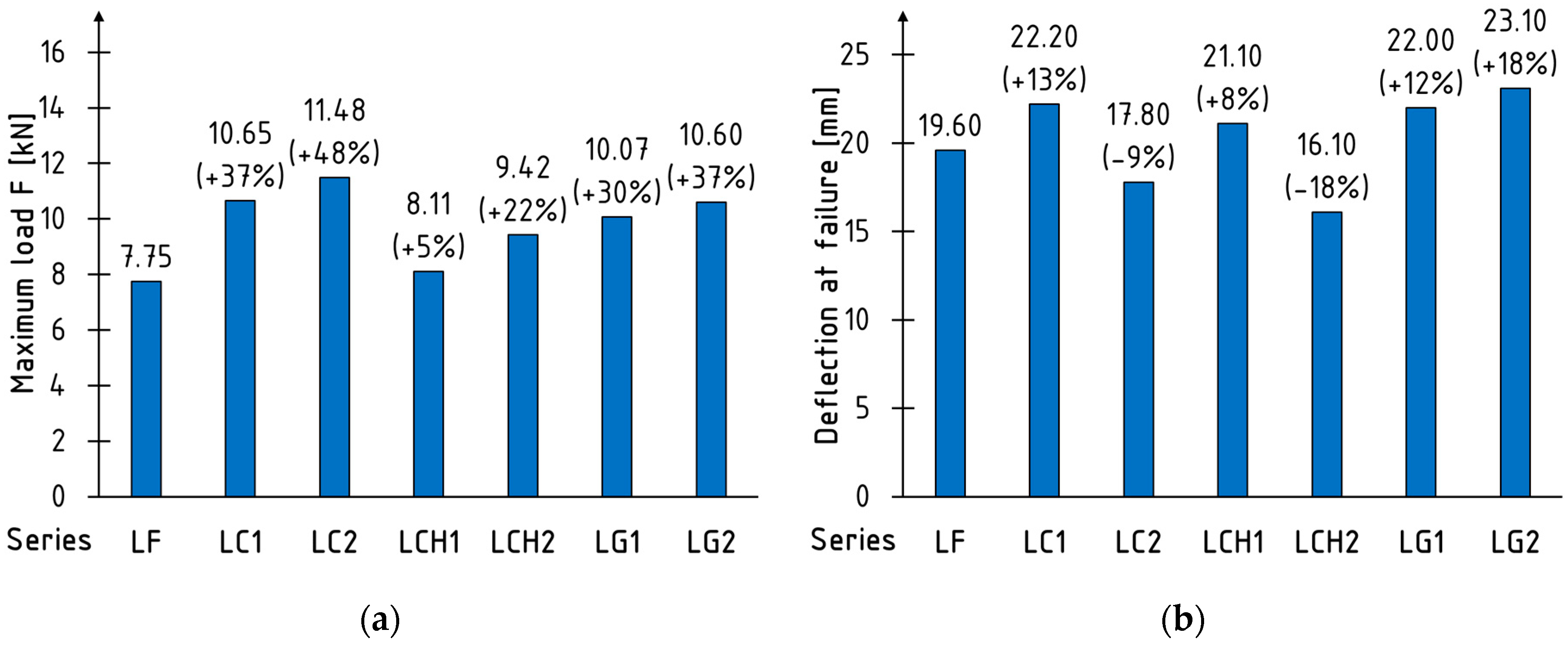
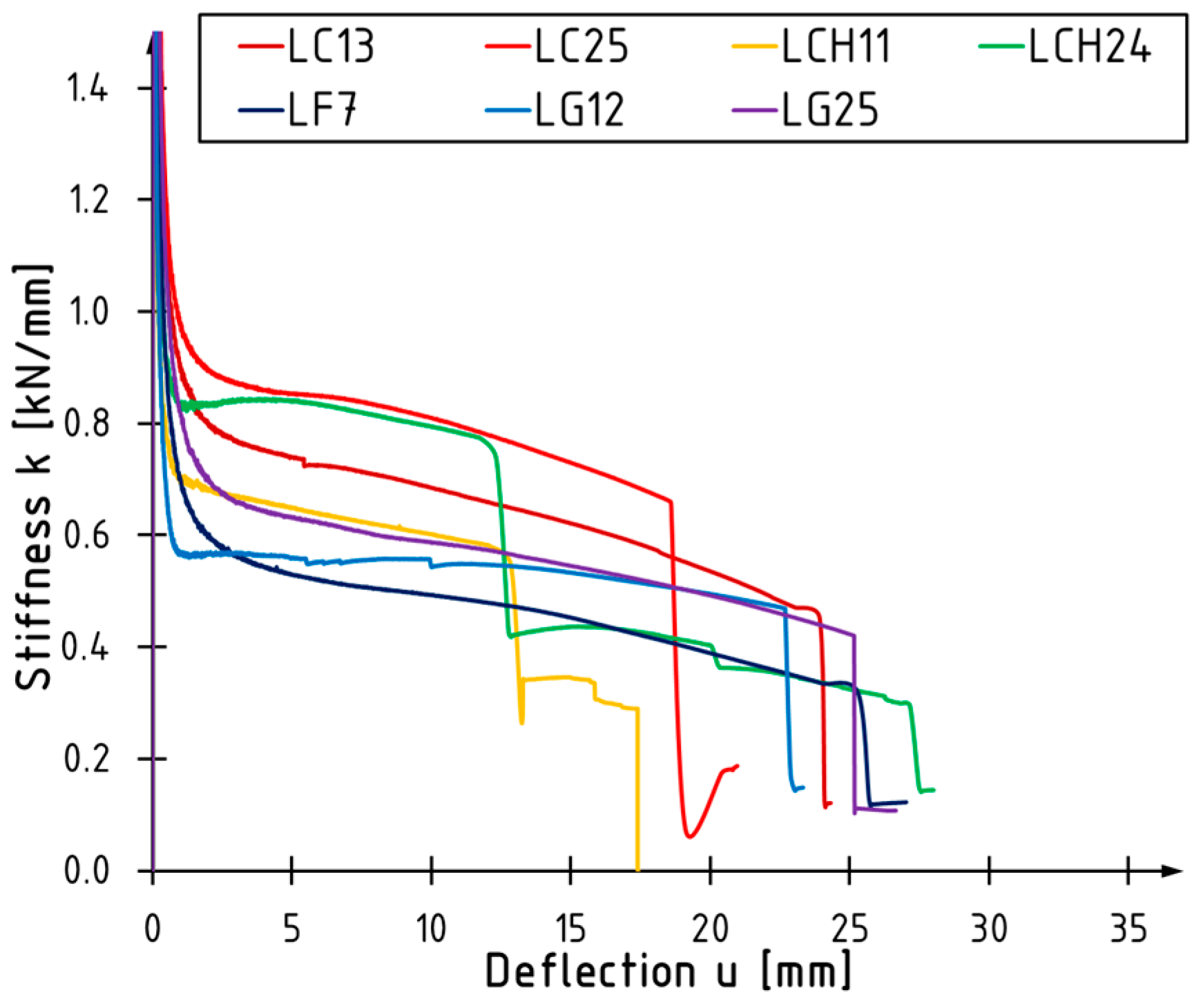
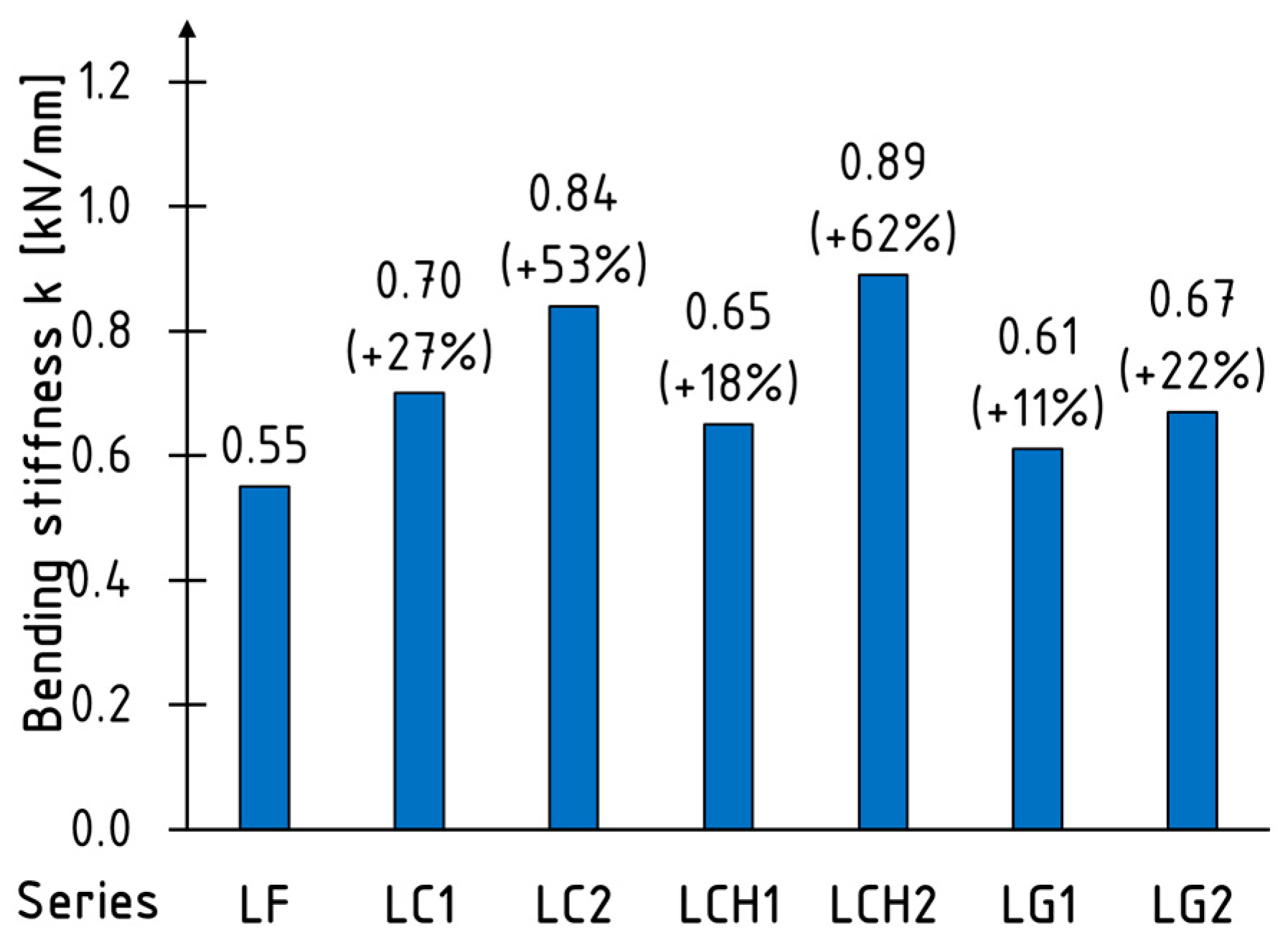
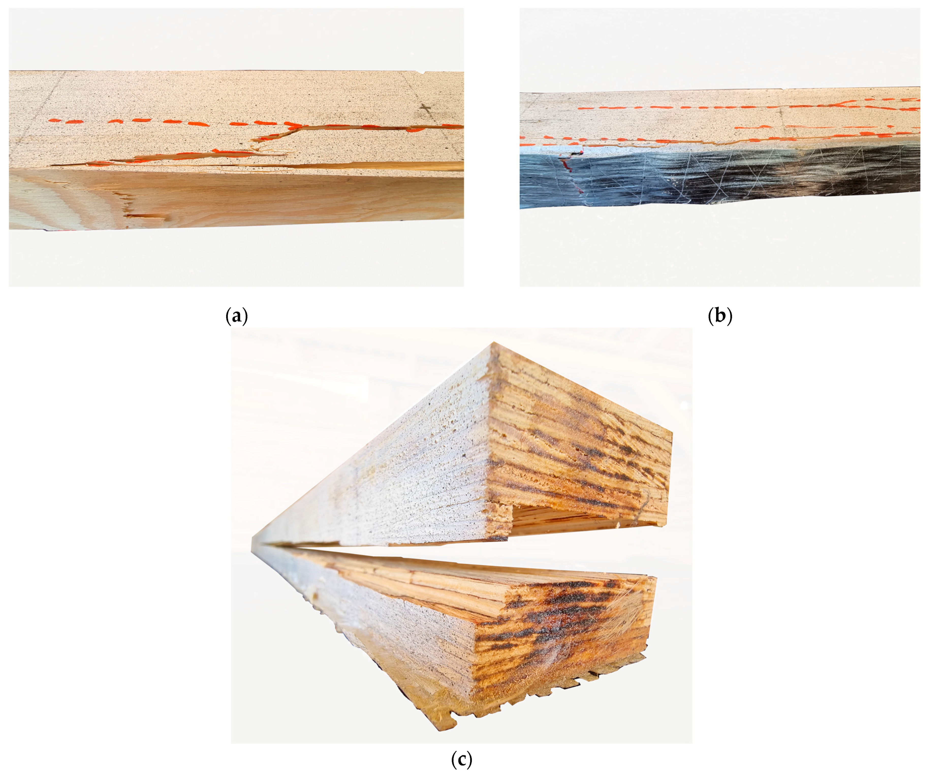
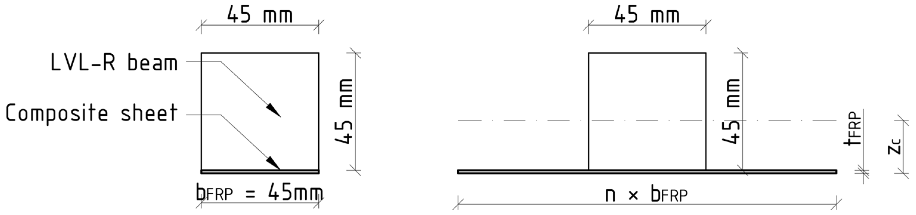
This paper presents the results of preliminary research on reinforcing slabs made of laminated veneer lumber with composite sheets bonded to the bottom surfaces with epoxy resin. As reinforcement, GFRP, CFRP, and UHM CFRP sheets were used. The tests were conducted on small-scale panel samples in so-called four-point bending tests.
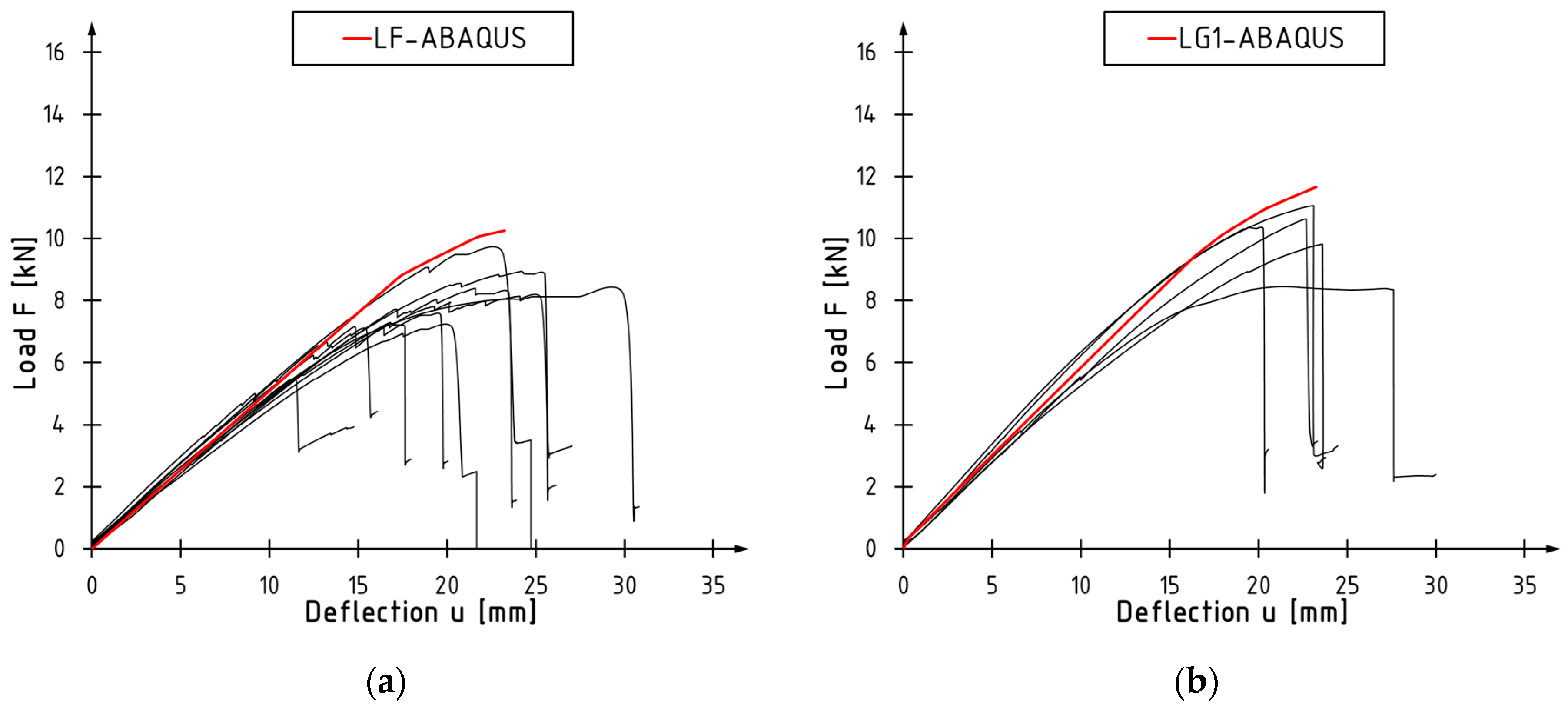
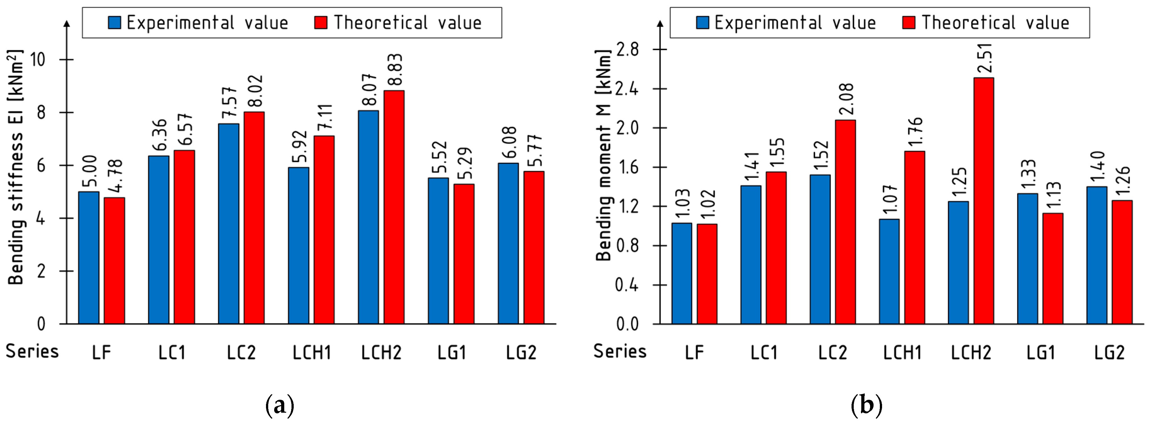
From a mechanical point of view, a positive influence of FRP reinforcement in terms of bending stiffness and load-bearing capacity on the behavior of the composite section was achieved. The magnitude of this effect was related to both FRP and LVL properties. For the FRP sheets, the modulus of elasticity and elongation at rupture of the reinforcement were crucial parameters. Typically, the higher the reinforcement ratio/modulus of elasticity is, the more effective the solution is. However, the low elongation at rupture of FRP can limit this effect. The most effective configuration, from among the proposed options, comprised two layers of CFRP. For LVL, the further improvements were limited by its shear failure in the support zone.
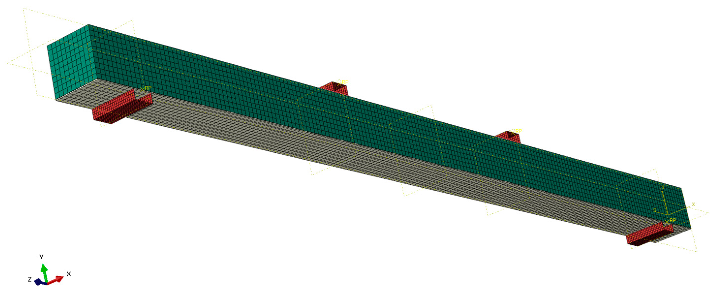
A good agreement between experimental and theoretical values of bending stiffness was obtained for the presented numerical and mathematical model. Both of them, however, are not able to capture the failure of the composite and, therefore, are not suitable for the estimation of load-bearing capacity. More work needs to be done to incorporate the shear failure of LVL to models.
Several limitations of this work need to be pointed out. First of all, the test were conducted on small samples and needs to be repeated on full-scale elements to evaluate the scale effect. Secondly, tests were conducted in a controlled environment; further tests on the fire performance and influence of the fluctuation of moisture content should be considered. And, lastly, only static behavior was evaluated.

Author Contributions

Conceptualization, M.M.B.; methodology, M.M.B. and P.G.K.; software, M.M.B.; validation, M.M.B.; formal analysis, M.M.B.; investigation, M.M.B.; writing—original draft preparation, M.M.B.; writing—review and editing, M.M.B. and P.G.K.; supervision, P.G.K. All authors have read and agreed to the published version of the manuscript.

Funding

The tests were implemented thanks to the financial support of the Kielce University of Technology within the framework of the statutory work No. 02.0.20.00/1.02.001, SUBB. BKTK. 23.002.

Data Availability Statement

No new data were created in this research.

Acknowledgments

The authors would also like to thank S&P Polska Sp. z o.o. for providing the research materials.

Conflicts of Interest

The authors declare no conflicts of interest.

References

  1. Schober, K.-U.; Harte, A.M.; Kliger, R.; Jockwer, R.; Xu, Q.; Chen, J.-F. FRP reinforcement of timber structures. Constr. Build. Mater. 2015, 97, 106–118. [Google Scholar] [CrossRef]
  2. Franke, S.; Franke, B.; Harte, A.M. Failure modes and reinforcement techniques for timber beams—State of the art. Constr. Build. Mater. 2015, 97, 2–13. [Google Scholar] [CrossRef]
  3. Radford, D.W.; Van Goethem, D.; Gutkowski, R.M.; Peterson, M.L. Composite repair of timber structures. Constr. Build. Mater. 2002, 16, 417–425. [Google Scholar] [CrossRef]
  4. Brol, J. Strengthening of bent glued laminated (glulam) beams with GARP tapes at the stage of production. Wiadomości Konserw. 2009, 26, 345–353. [Google Scholar]
  5. Ehsani, M.; Larsen, M.; Palmer, N. Strengthening of Old Wood with New Technology. Structure. February 2004, pp. 19–21. Available online: https://quakewrap.com/frp%20papers/Strengthening-of-Old-Wood-with-New-Technology.pdf (accessed on 17 December 2023).
  6. Rescalvo, F.J.; Valverde-Palacios, I.; Suarez, E.; Gallego, A. Experimental and analytical analysis for bending load capacity of old timber beams with defects when reinforced with carbon fiber strips. Constr. Build. Mater. 2018, 186, 29–38. [Google Scholar] [CrossRef]
  7. Kossakowski, P.G.; Bakalarz, M. Sztywność na zginanie belek z forniru klejonego warstwowo wzmocnionych matami węglowymi o ultrawysokim module sprężystości. Inżynieria I Bud. 2019, 1, 47–50. [Google Scholar]
  8. Saribiyik, M.; Akgul, T.; Apay, A.C.; Saribiyik, A. Bending Analysis of Timber Connection Strengthen with Glass Fiber Reinforced Plastic. In Proceedings of the First International Symposium on Sustainable Development, Sarajevo, Bosnia and Herzegovina, 9–10 June 2009. [Google Scholar]
  9. Kossakowski, P.G.; Bakalarz, M. The flexural capacity of laminated veneer lumber beams strengthened with AFRP and GFRP sheets. Tech. Trans. 2019, 2, 85–95. [Google Scholar] [CrossRef]
  10. Raftery, G.M.; Kelly, F. Basalt FRP rods for reinforcement and repair of timber. Compos. B Eng. 2015, 70, 9–19. [Google Scholar] [CrossRef]
  11. Nowak, T.P.; Jasieńko, J.; Czepiżak, D. Experimental tests and numerical analysis of historic bent timber elements reinforced with CFRP strips. Constr. Build. Mater. 2013, 40, 197–206. [Google Scholar] [CrossRef]
  12. Czaderski, C.; Meier, U. Long-term behaviour of CFRP. In Proceedings of the 2nd International Fib Congress, Naples, Italy, 5–8 June 2006. [Google Scholar]
  13. Raftery, G.M.; Harte, A.M. Low-grad glued laminated timber reinforced with FRP plate. Compos. B Eng. 2011, 42, 724–735. [Google Scholar] [CrossRef]
  14. Navaratnam, S.; Rajeev, P. Load-Carrying Capacity of Laminated Veneer Lumber Joists with Notches and Holes. J. Struct. Eng. 2023, 149, 04023178. [Google Scholar] [CrossRef]
  15. Burawska, I.; Mohammadi, A.M.; Widmann, R.; Motavalli, M. Local reinforcement of timber beams using D-shape CFRP strip. In Proceedings of the SMAR 2015—Third Conference on Smart Monitoring, Assessment and Rehabilitation of Civil Construction, Antalya, Turkey, 7–9 September 2015. [Google Scholar]
  16. De Jesus, A.M.; Pinto, J.M.; Morais, J.J. Analysis of solid wood beams strengthened with CFRP laminates of distinct lengths. Constr. Build. Mater. 2012, 35, 817–828. [Google Scholar] [CrossRef]
  17. Xian, G.; Guo, R.; Li, C. Combined effects of sustained bending loading, water immersion and fiber hybrid mode on the mechanical properties of carbon/glass fiber reinforced polymer composite. Comp. Struc. 2022, 281, 115060. [Google Scholar] [CrossRef]
  18. Dewey, J.; Burry, M.; Tuladhar, R.; Sivakugan, N.; Pandey, G.; Stphenson, D. Strengthening and rehabilitation of deteriorated timber bridge girders. Constr. Build. Mater. 2018, 185, 302–309. [Google Scholar] [CrossRef]
  19. Kim, Y.; Oh, H. Comparison between Multiple Regression Analysis, Polynomial Regression Analysis, and an Artificial Neural Network for Tensile Strength Prediction of BFRP and GFRP. Materials 2021, 14, 4861. [Google Scholar] [CrossRef] [PubMed]
  20. Wu, J.; Zhu, Y.; Li, C. Experimental Investigation of Fatigue Capacity of Bending-Anchored CFRP Cables. Polymers 2023, 15, 2483. [Google Scholar] [CrossRef] [PubMed]
  21. Núñez-Decap, M.; Sandoval-Valderrama, B.; Opazo-Carlsson, C.; Moya-Rojas, B.; Vidal-Vega, M.; Opazo-Vega, A. Use of Carbon and Basalt Fibers with Adhesives to Improve Physical and Mechanical Properties of Laminated Veneer Lumber. Appl. Sci. 2023, 13, 10032. [Google Scholar] [CrossRef]
  22. Sokolović, N.M.; Gavrilović-Grmuša, I.; Zdravković, V.; Ivanović-Šekularac, J.; Pavićević, D.; Šekularac, N. Flexural Properties in Edgewise Bending of LVL Reinforced with Woven Carbon Fibers. Materials 2023, 16, 3346. [Google Scholar] [CrossRef] [PubMed]
  23. Sokołowski, P.; Kossakowki, P. Static Analysis of Wooden Beams Strengthened with FRCM-PBO Composite in Bending. Materials 2023, 16, 1870. [Google Scholar] [CrossRef]
  24. Rescalvo, F.J.; Duriot, R.; Pot, G.; Gallego, A.; Denaud, L. Enhancement of bending properties of Douglas-fir and poplar laminate veneer lumber (LVL) beams with carbon and basalt fibers reinforcement. Constr. Build. Mater. 2020, 263, 120185. [Google Scholar] [CrossRef]
  25. Subhani, M.; Globa, A.; Al-Ameri, R.; Moloney, J. Flexural strengthening of LVL beam using CFRP. Constr. Build. Mater. 2017, 150, 380–389. [Google Scholar] [CrossRef]
  26. Bal, C.B. Flexural properties, bonding performance and splitting strength of LVL reinforced with woven glass fiber. Constr. Build. Mater. 2014, 51, 9–14. [Google Scholar] [CrossRef]
  27. Acosta, A.P.; Delucis, R.; Amico, S.C. Hybrid wood-glass and wood-jute-glass laminates manufactured by vacuum infusion. Constr. Build. Mater. 2023, 398, 132513. [Google Scholar] [CrossRef]
  28. Chybiński, M.; Polus, Ł. Experimental and numerical investigations of laminated veneer lumber panels. Arch. Civ. Eng. 2021, 67, 351–372. [Google Scholar] [CrossRef]
  29. Chybiński, M.; Polus, Ł. Belki zespolone aluminiowo-drewniane łączone za pomocą wkrętów lub śrub—Podsumowanie i wnioski z badań własnych [Aluminium-timber composite beams with screwed or bolted connections—Summary and conclusions from own research]. Przegląd Bud. 2023, 94, 56–60. [Google Scholar] [CrossRef]
  30. PN-EN 408+A1:2012; Timber Structures. Structural Timber and Glued Laminated Timber. Determination of Some Physical and Mechanical Properties. PKN: Warszawa, Poland, 2012.
  31. PN-EN 14374:2005; Timber Structures. Structural Laminated Veneer Lumber (LVL). Requirements. PKN: Warszawa, Poland, 2005.
  32. Bakalarz, M. Load bearing capacity of laminated veneer lumber beams strengthened with CFRP strips. Arch. Civ. Eng. 2021, 67, 139–155. [Google Scholar] [CrossRef]
  33. Bakalarz, M. Efektywność Wzmacniania Zginanych Belek z Drewna Klejonego Warstwowo z Fornirów za Pomocą Komozytów Włóknistych (Effectiveness of Strengthening of Bent Laminated Veneer Lumber Beams with Fibrous Composites). Ph.D. Thesis, Kielce University of Technology, Kielce, Poland, 2022. [Google Scholar]
  34. STEICO. STEICO LVL R—Fornir Klejony Warstwowo. Available online: https://www.steico.com/pl/produkty/produkty-konstrukcyjne/fornir-klejony-warstwowo-lvl/steico-lvl-r-fornir-klejony-warstwowo (accessed on 27 October 2023).
  35. S&P C-Sheet 240—Technical Information. Available online: https://www.sp-reinforcement.pl/sites/default/files/field_product_col_doc_file/c-sheet_240_polska_ver20190627.pdf (accessed on 19 September 2022).
  36. S&P G-Sheet E 90/10, Typ B; S&P G-Sheet AR 90/10, Typ B—Technical Information. Available online: https://www.sp-reinforcement.pl/sites/default/files/field_product_col_doc_file/g_sheet_e_ar_90_10_typ_b_polska_ver012019_low.pdf (accessed on 29 December 2022).
  37. S&P C-Sheet 640—Technical Information. Available online: https://www.sp-reinforcement.pl/sites/default/files/field_product_col_doc_file/c-_sheet_640_polska_ver012019_low.pdf (accessed on 29 December 2022).
  38. EN 13412:2008; Products and Systems for The Protection and Repair of Concrete Structures. Test Methods. Determination of Modulus of Elasticity in Compression. Polish Committee for Standardization: Warsaw, Poland, 2008.
  39. EN 12190:1999; Products and Systems for the Protection and Repair of Concrete Structures. Test Methods. Determination of Compressive Strength of Repair Mortar. British Standards Institution: London, UK, 1999.
  40. S&P Resin 55 HP–Technical Information. Available online: https://www.sp-reinforcement.pl/sites/default/files/field_product_col_doc_file/resin55_hp_polska_ver20190523.pdf (accessed on 19 September 2022).
  41. Bakalarz, M.; Kossakowski, P.G. Load-bearing capacity of solid timber beams with small cross section height strengthened with composite sheets. Struct. Environ. 2018, 4, 301–308. [Google Scholar] [CrossRef]
  42. Bakalarz, M.M.; Kossakowski, P. Ductility and Stiffness of Laminated Veneer Lumber Beams Strengthened with Fibrous Composites. Fibers 2022, 10, 21. [Google Scholar] [CrossRef]
  43. Bakalarz, M.M.; Kossakowski, P.G. Numerical, Theoretical and Experimental Analysis of LVL-CFRP Sandwich Structure. Materials 2024, 17, 61. [Google Scholar] [CrossRef]
  44. Kawecki, B. Dobór Parametrów Modeli Obliczeniowych Pełnych Dźwigarów z Kompozytów Drewno-Polimerowych Zbrojonych Włóknami. Ph.D. Thesis, Lublin University of Technology, Lublin, Poland, 2021. [Google Scholar]
  45. Szczecina, M. Study of Complexity of Numerical Models of a Strengthened Timber Beam. Materials 2023, 16, 3466. [Google Scholar] [CrossRef]
  46. Bakalarz, M.M.; Kossakowski, P.G. Application of transformed cross section method for analytical analysis of laminated veneer lumber beams strengthened with composite materials. Fibers 2023, 11, 24. [Google Scholar] [CrossRef]
  47. Masłowski, E.; Spiżewska, D. Wzmacnianie Konstrukcji Budowlanych; Wydawnictwo Arkady: Warszawa, Poland, 2000. [Google Scholar]
  48. Rudziński, L. Konstrukcje Drewniane. Naprawy, Wzmocnienia, Przykłady Obliczeń; Wydawnictwo Politechniki Świętokrzyskiej: Kielce, Poland, 2010. [Google Scholar]
  49. Timbolmas, C.; Bravo, R.; Rescalvo, F.J.; Gallego, A. Development of analytical model to predict the bending behavior of composite glulam beams in tension and compression. J. Build. Eng. 2022, 45, 103471. [Google Scholar] [CrossRef]
  50. Nadir, Y.; Nagarajan, P.; Ameen, M.; Arif, M.M. Flexural stiffness and strength engancement of horizontally glued laminated wood beams with GFRP and CFRP composite sheets. Constr. Build. Mater. 2016, 112, 547–555. [Google Scholar] [CrossRef]
  51. Soriano, J.; Pellis, B.P.; Mascia, N.T. Mechanical performance of glued-laminated timber beams symmetrically reinforced with steel bars. Compos. Struct. 2016, 150, 200–207. [Google Scholar] [CrossRef]
Figure 1. Tested specimens (photo taken by author).
Fibers 12 00022 g001
Figure 2. Composite sheets (photo taken by author).
Fibers 12 00022 g002
Figure 3. Reinforcement configurations.
Fibers 12 00022 g003
Figure 4. Static diagram of the test bench.
Fibers 12 00022 g004
Figure 5. View of the test bench (photo taken by author).
Fibers 12 00022 g005
Figure 6. Load deflection curves of unreinforced beams.
Fibers 12 00022 g006
Figure 7. Load deflection curves of reinforced beams: (a) LC1 series; (b) LC2 series; (c) LCH1 series; (d) LCH2 series; (e) LG1 series; (f) LG2 series.
Fibers 12 00022 g007
Figure 8. Average values of (a) maximum load F and (b) deflection at maximum load.
Fibers 12 00022 g008
Figure 9. Stiffness deflection curves for selected tested samples.
Fibers 12 00022 g009
Figure 10. Average values of bending stiffness.
Fibers 12 00022 g010
Figure 11. Failure examples: (a) tension; (b) rupture of FRP material; (c) shear.
Fibers 12 00022 g011
Figure 12. Prepared model in Abaqus environment.
Fibers 12 00022 g012
Figure 13. Curves obtained from FEM model plotted against experimental results for (a) unreinforced beams and (b) beams reinforced with GFRP sheets.
Fibers 12 00022 g013
Figure 14. Transformed cross-section.
Fibers 12 00022 g014
Figure 15. Comparison of experimental and theoretical values: (a) bending stiffness EI; (b) bending moment M.
Fibers 12 00022 g015
Table 1. Physical and mechanical properties of laminated veneer lumber (adapted from [32,33] according to own research and manufacturer data [34]).
ParameterValue
Bending strength (edgewise condition) fm,0,edge [MPa]80
Bending strength (flatwise condition) fm,0,flat [MPa]66 1
Modulus of elasticity in bending (parallel to grain) E0,mean [GPa]14.0
Compression strength (parallel to grain) fc,0,k [MPa]58.5
Compression strength (perpendicular to grain) fc,90,k [MPa]9.5
Shear strength (parallel to grain) fv,k [MPa]2.6
Mean value of density ρd [kg/m3]600
Average moisture content of tested samples w [%]15.1 1
1 Based on results in this research.
Table 2. Selected mechanical and physical properties of FRP sheets (adapted from [32,33] according to manufacturer data [35,36,37]).
ParameterGFRPCFRPCFRP UHM
Modulus of elasticity Ef [GPa]73265640
Tensile strength ft,f [MPa]340051002600
Fiber mass [g/m2]800600400
Sheet mass [g/m2]880630430
Density ρf [kg/m3]260018002120
Elongation at rupture εf [%]4.51.7–1.90.4
Design (reinforcement) thickness tf [mm]0.308—one layer; 0.616—two layers0.333—one layer; 0.666—two layers0.189—one layer;
0.378—two layers
Table 3. Selected mechanical and physical properties of adhesive (adapted from [32,33] according to the manufacturer data [40]).
ParameterValue
Modulus of elasticity Ek [MPa]3200
Density ρk [kg/m3]1200–1300
Compressive strength fc,k [MPa]100
Table 4. Test results of LF series.
ParameterBeamMV (SD)
LF1LF2LF3LF4LF5LF6LF7LF8LF9LF10
Fmax [kN]7.305.448.957.077.538.408.069.497.088.147.75 (1.08)
Mmax [kN]0.970.721.190.941.001.111.071.260.941.081.03 (0.14)
umax [mm]16.811.524.215.518.521.623.721.118.524.019.6 (3.96)
Failure modeShearTensionShearTensionTensionTensionTensionTensionTensionTension-
Table 5. Test results of LC1 series.
ParameterBeamMV (SD)
LC11LC12LC13LC14LC15
Fmax [kN]10.6111.7410.899.8310.2010.65 (0.65)
Mmax [kN]1.411.561.331.301.351.41 (0.09)
umax [mm]30.221.221.816.321.622.2 (4.48)
Failure modeShearShearShearShearShear-
Table 6. Test results of LC2 series.
ParameterBeamMV (SD)
LC21LC22LC23LC24LC25
Fmax [kN]11.1511.1811.5411.2512.2611.48 (0.42)
Mmax [kN]1.481.481.531.491.621.52 (0.06)
umax [mm]19.817.017.116.718.617.8 (1.17)
Failure modeShearShearShearShearShear-
Table 7. Test results of LCH1 series.
ParameterBeamMV (SD)
LCH11LCH12LCH13LCH14LCH15
Fmax [kN]7.047.929.886.709.038.11 (1.19)
Mmax [kN]0.931.051.310.891.201.07 (0.16)
umax [mm]12.824.230.719.718.021.1 (6.04)
Failure modeTension + Rupture of compositeTension + Rupture of compositeTension + Rupture of compositeTension + Rupture of compositeTension + Rupture of composite-
Table 8. Test results of LCH2 series.
ParameterBeamMV (SD)
LCH21LCH22LCH23LCH24LCH25
Fmax [kN]8.939.0310.639.089.419.42 (0.63)
Mmax [kN]1.181.201.411.201.251.25 (0.08)
umax [mm]14.522.213.312.318.016.1 (3.61)
Failure modeTension + Rupture of compositeTension + Rupture of compositeTension + Rupture of compositeTension + Rupture of compositeTension + Shear + Rupture of composite-
Table 9. Test results of LG1 series.
ParameterBeamMV (SD)
LG11LG12LG13LG14LG15
Fmax [kN]10.3610.648.4611.079.8310.07 (0.90)
Mmax [kN]1.371.411.121.471.301.33 (0.12)
umax [mm]19.522.721.323.123.622.0 (1.49)
Failure modeShearShearShearShearShear-
Table 10. Test results of LG2 series.
ParameterBeamMV (SD)
LG21LG22LG23LG24LG25
Fmax [kN]11.1610.2410.0111.0110.5810.60 (0.44)
Mmax [kN]1.481.361.331.461.401.40 (0.06)
umax [mm]22.624.323.819.825.123.1 (1.85)
Failure modeShearShearCompressionShearShear-
Disclaimer/Publisher’s Note: The statements, opinions and data contained in all publications are solely those of the individual author(s) and contributor(s) and not of MDPI and/or the editor(s). MDPI and/or the editor(s) disclaim responsibility for any injury to people or property resulting from any ideas, methods, instructions or products referred to in the content.

