

Repairing of One-Way Solid Slab Exposed to Thermal Shock Using CFRP: Experimental and Analytical Study

Abstract
:1. Introduction
2. Research Significance
3. Experimental Work
3.1. Materials
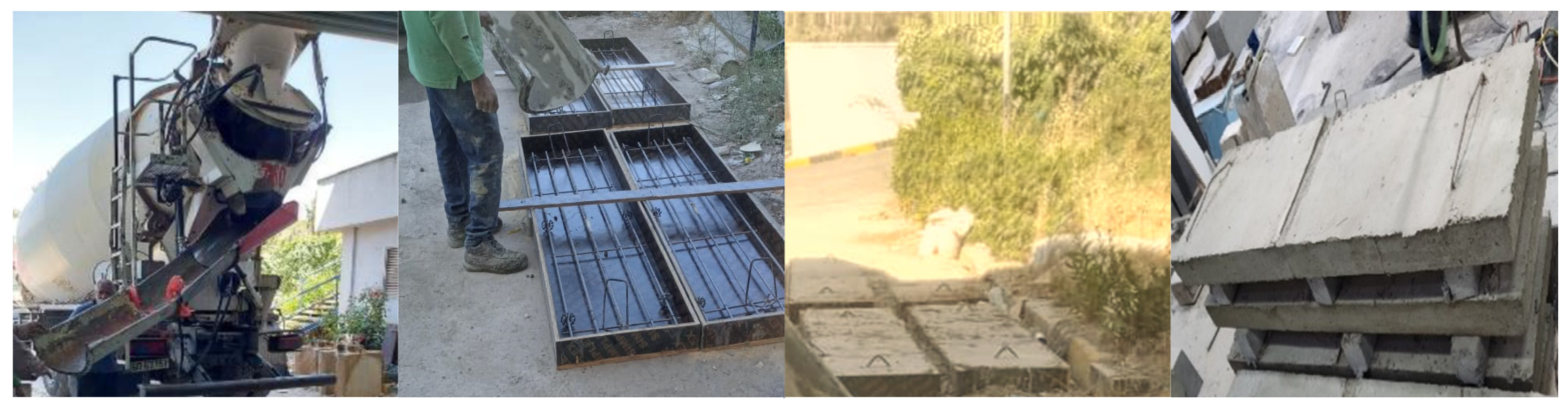
3.1.1. Concrete
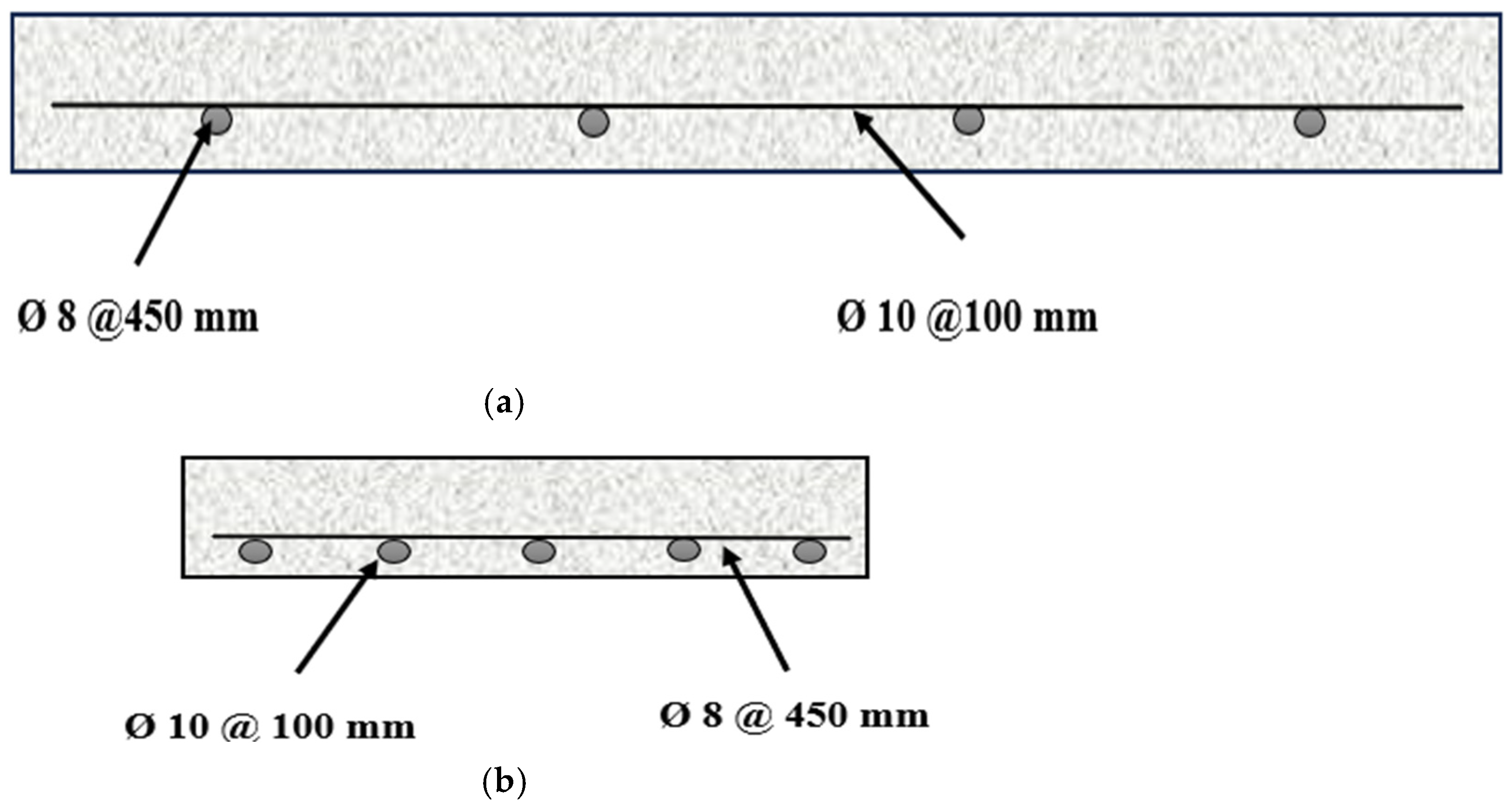
3.1.2. Steel Reinforcement
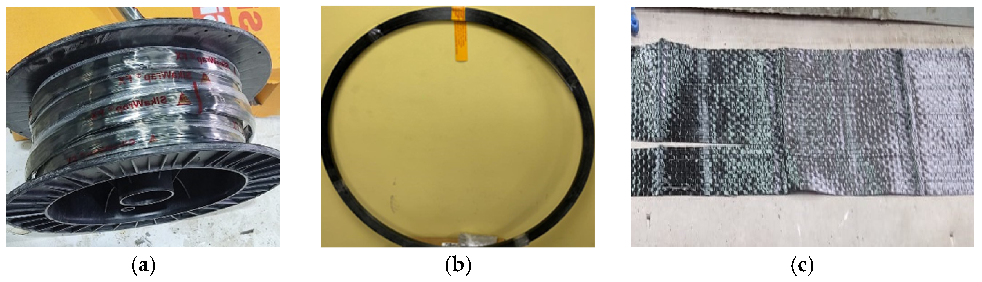
3.1.3. CFRP
3.1.4. Epoxy
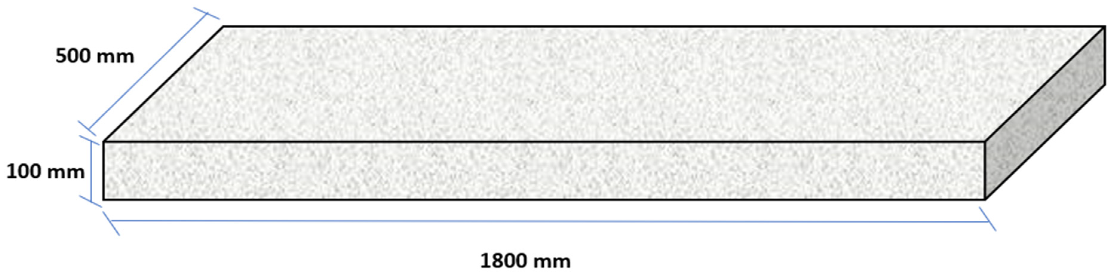
3.2. Slab Details
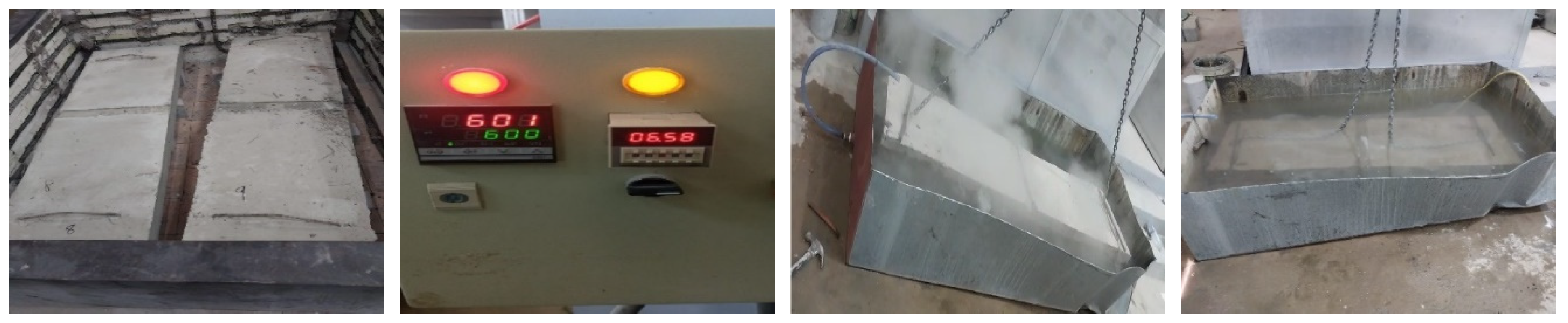
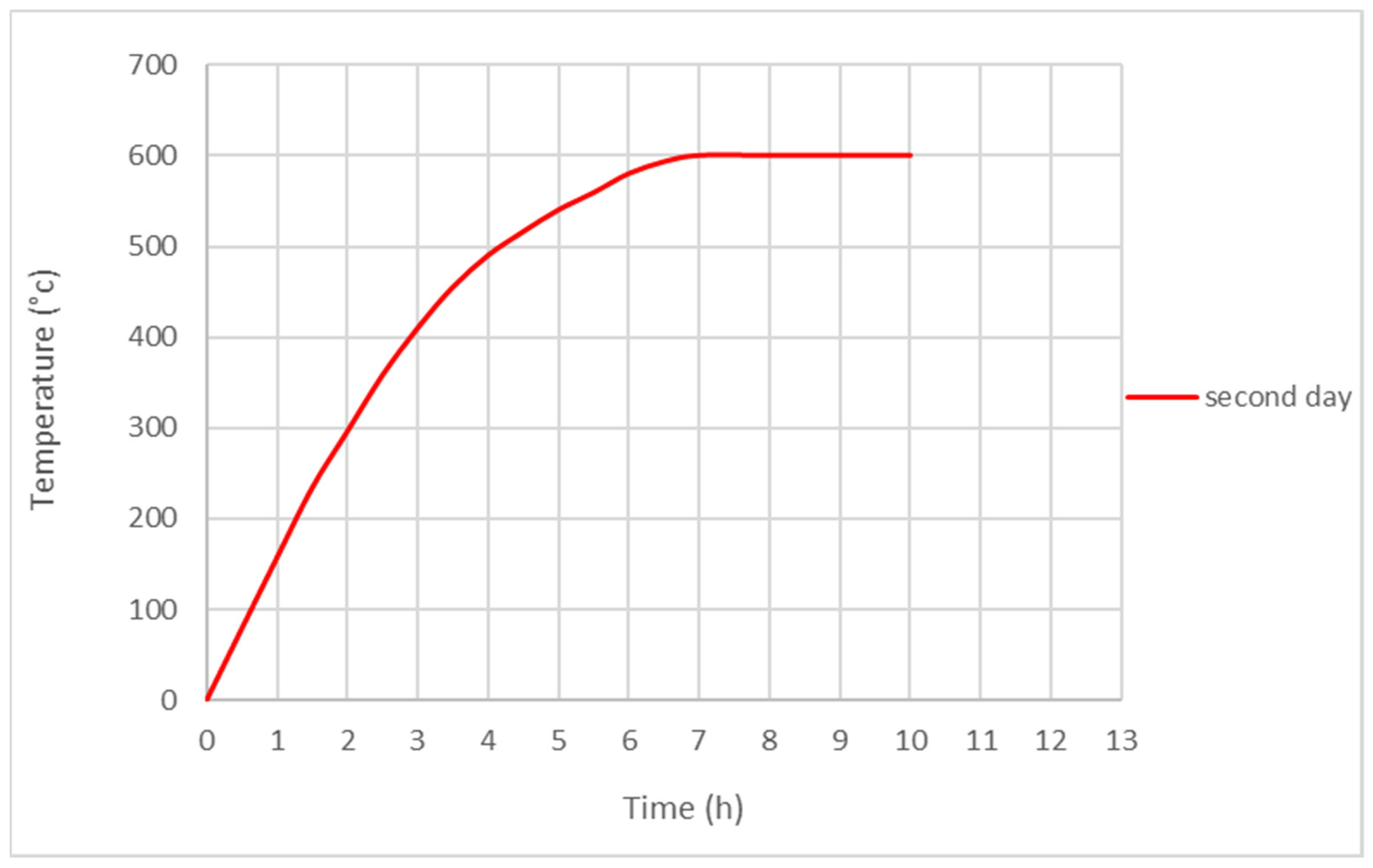
3.3. Thermal Shock Procedure
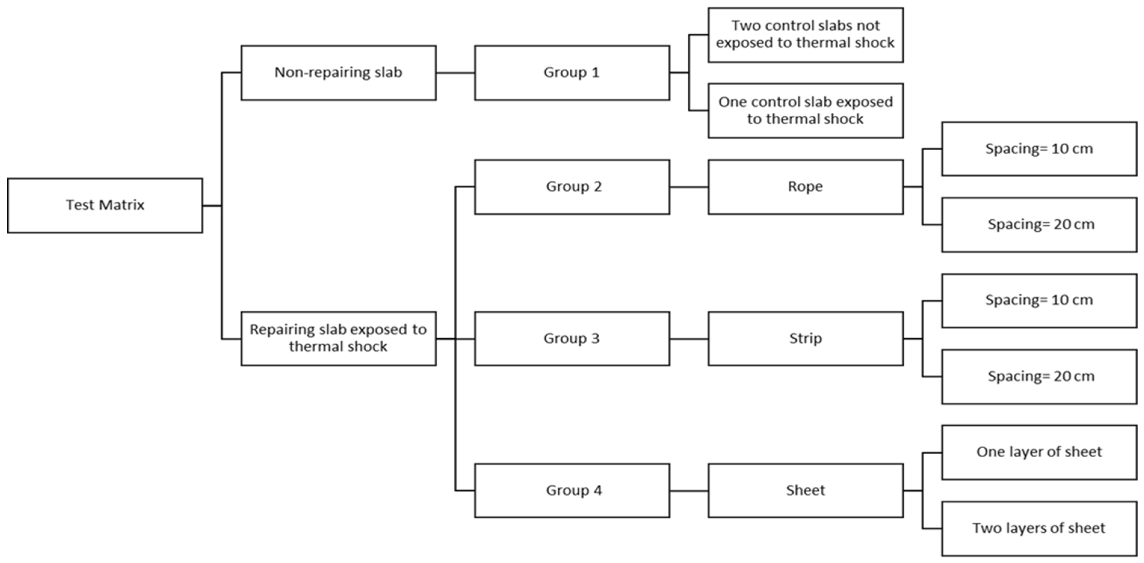
3.4. Test Matrix
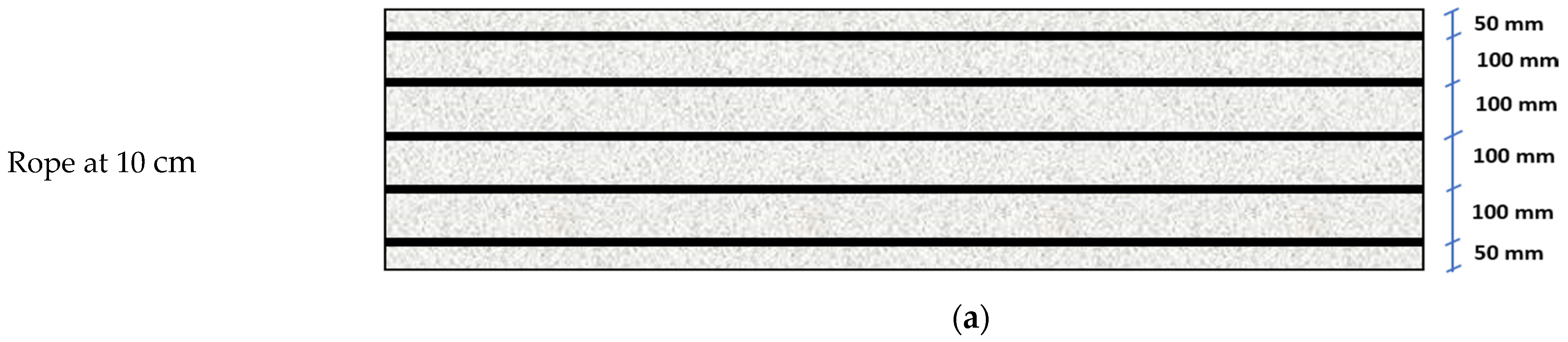
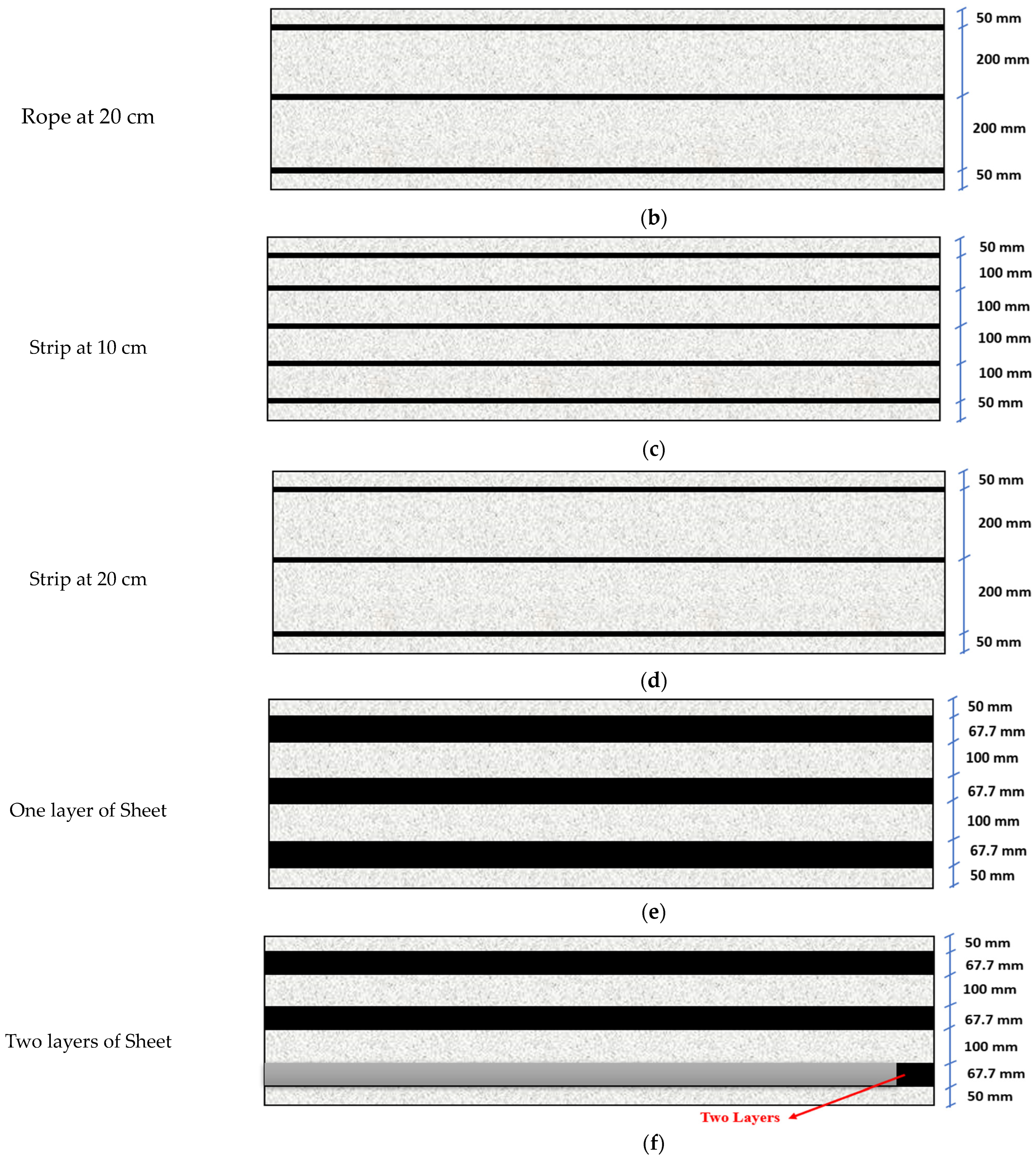
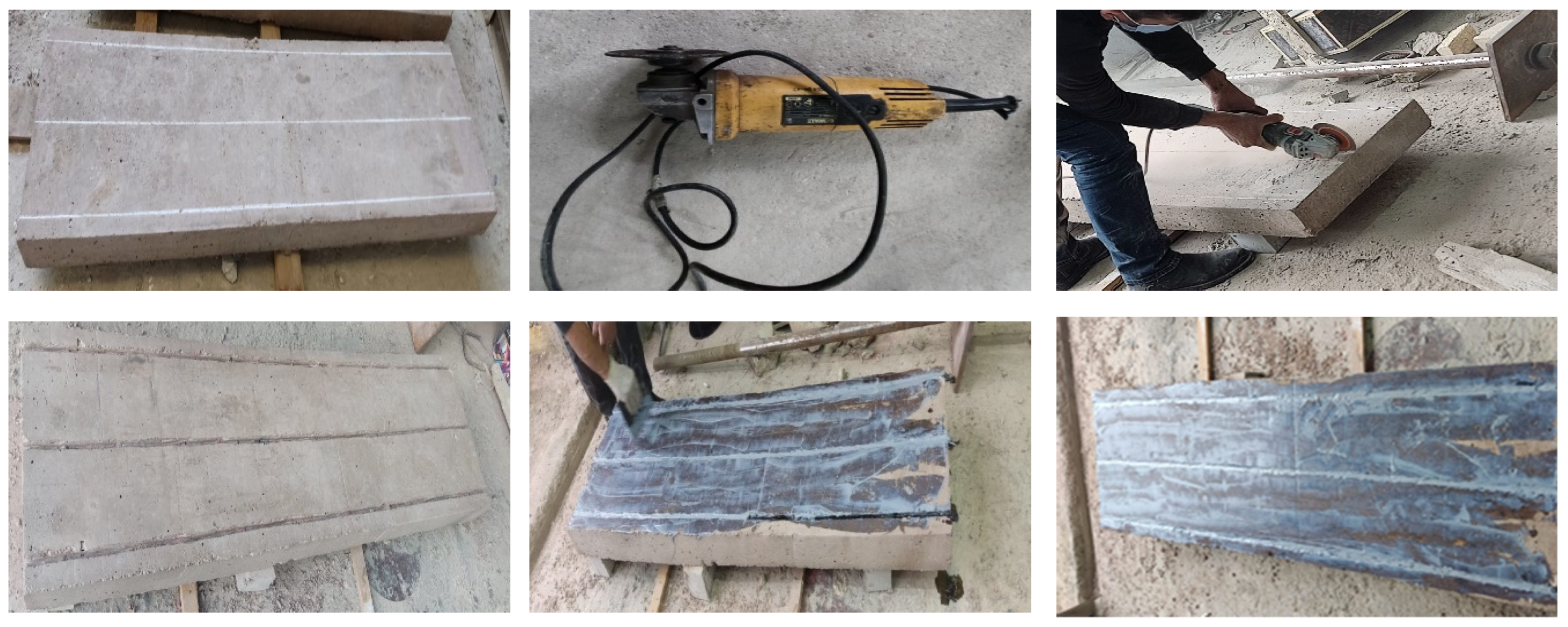
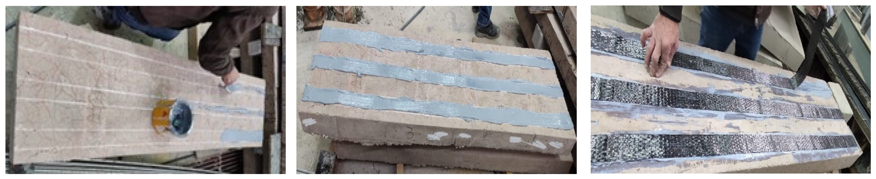
3.5. Installation of CFRP
3.5.1. CFRP Ropes and Strips Installation
3.5.2. CFRP Sheet Installation
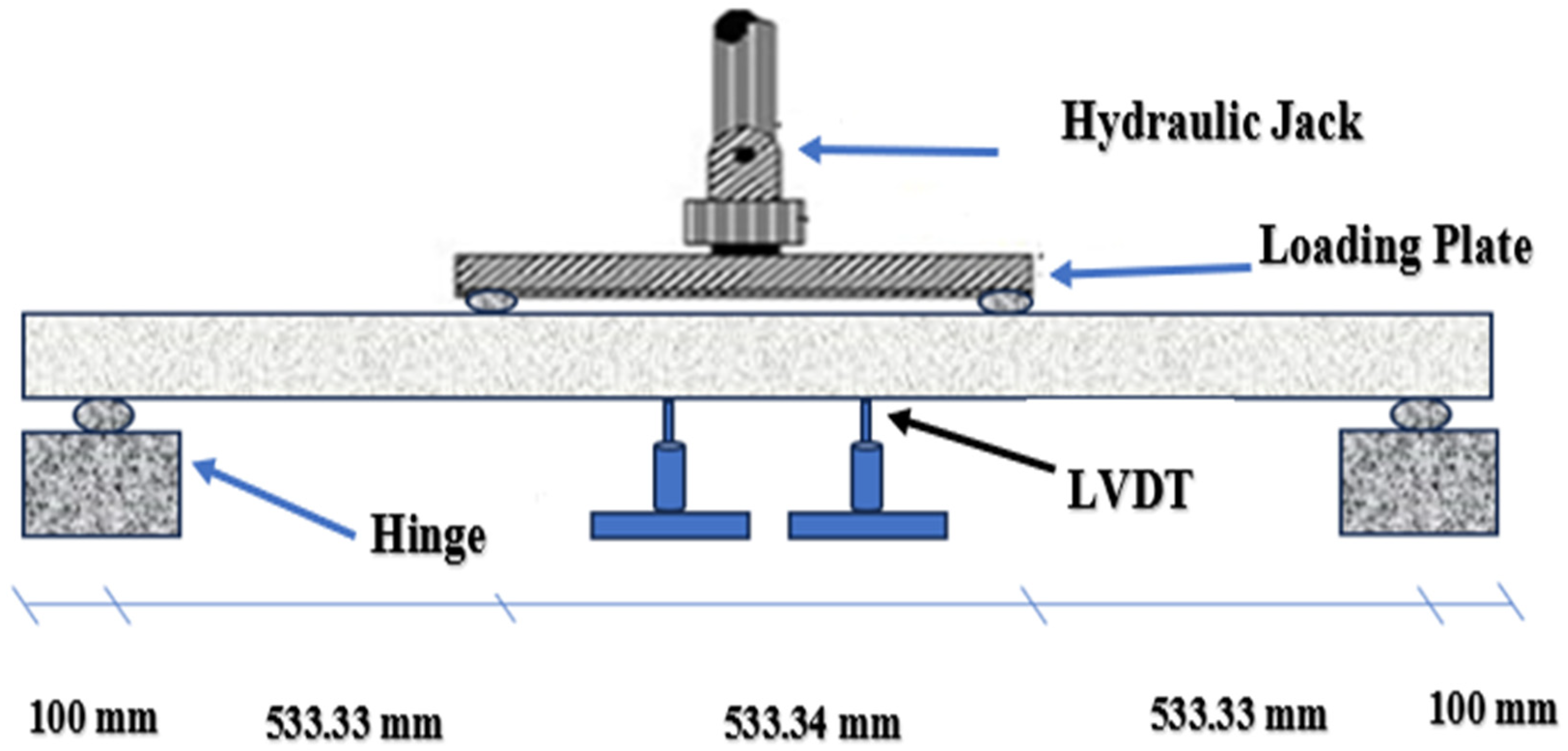
3.6. Test Setup
4. Experimental Results
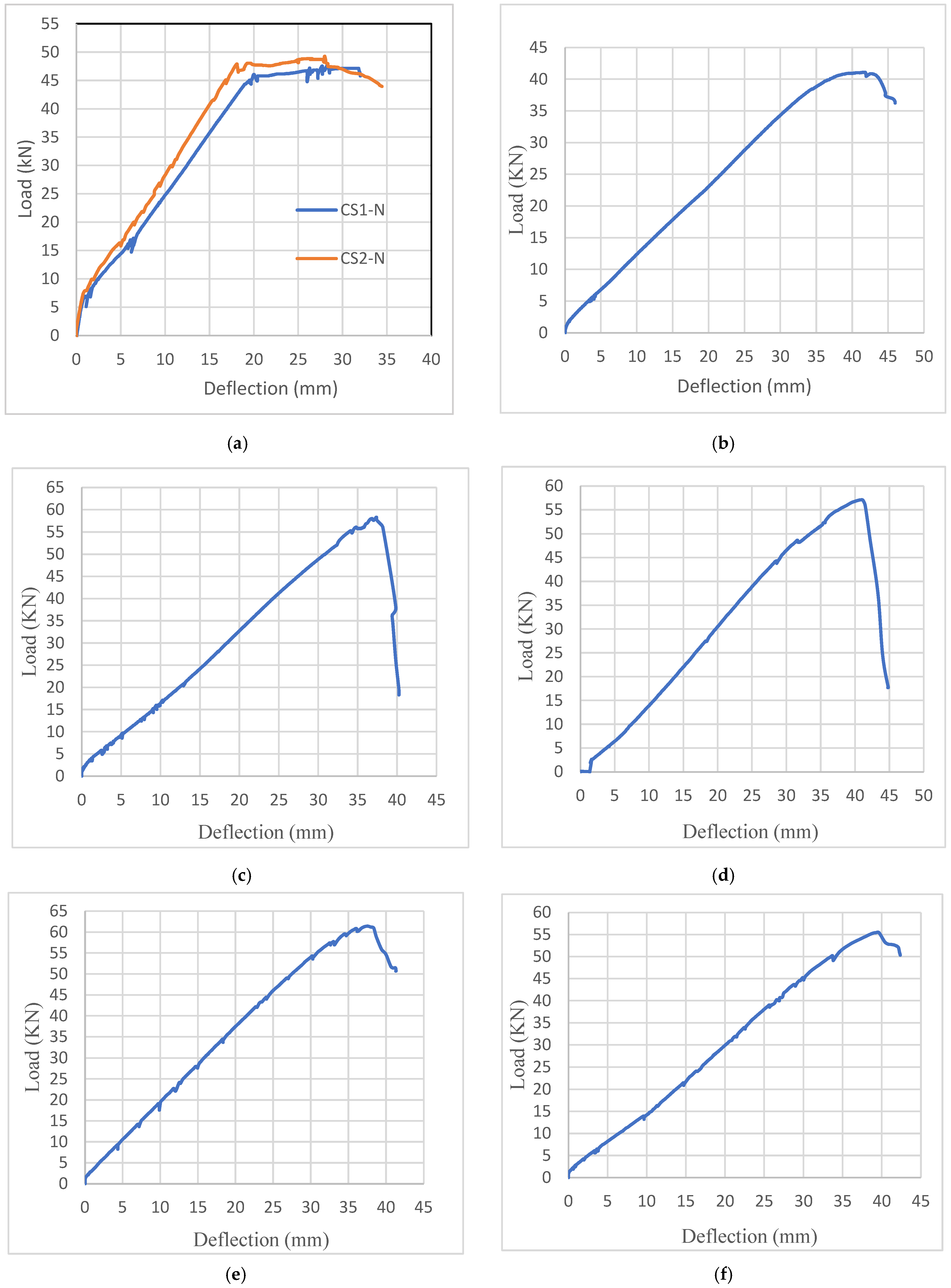
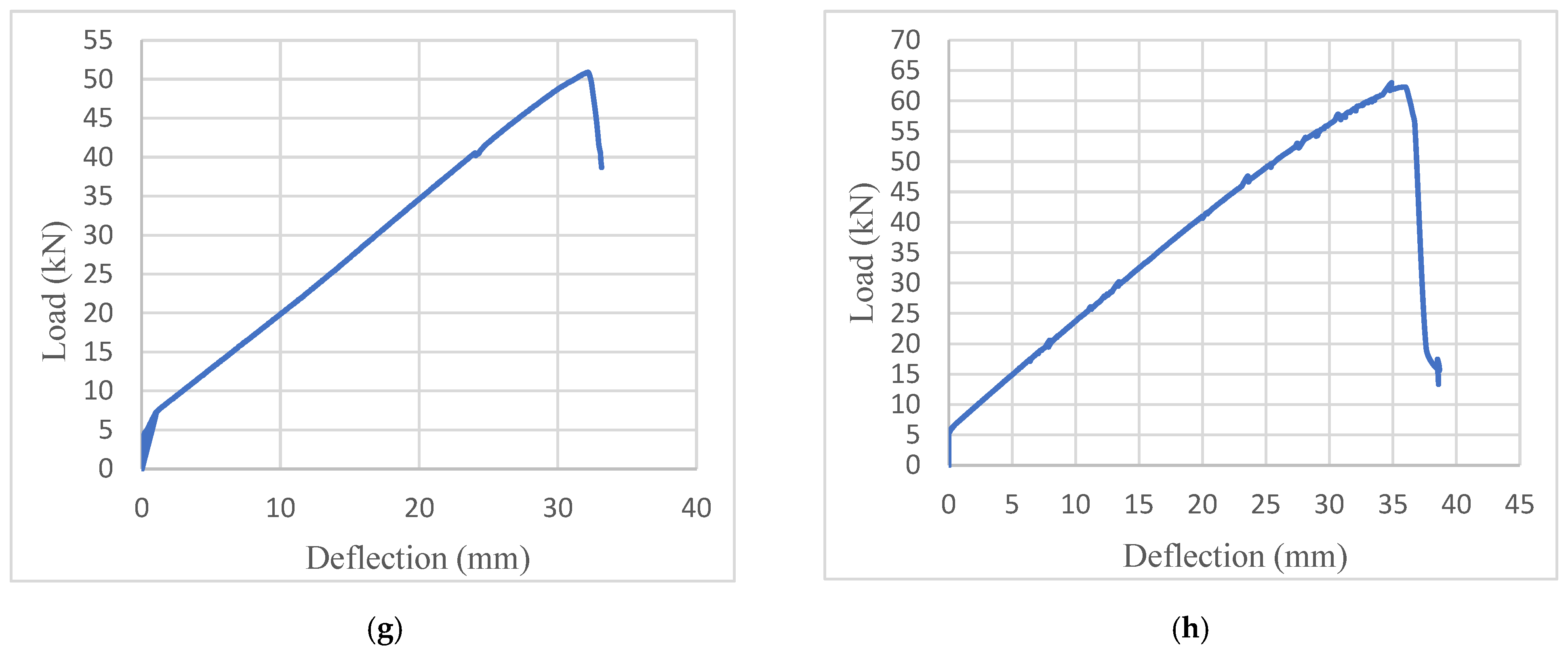
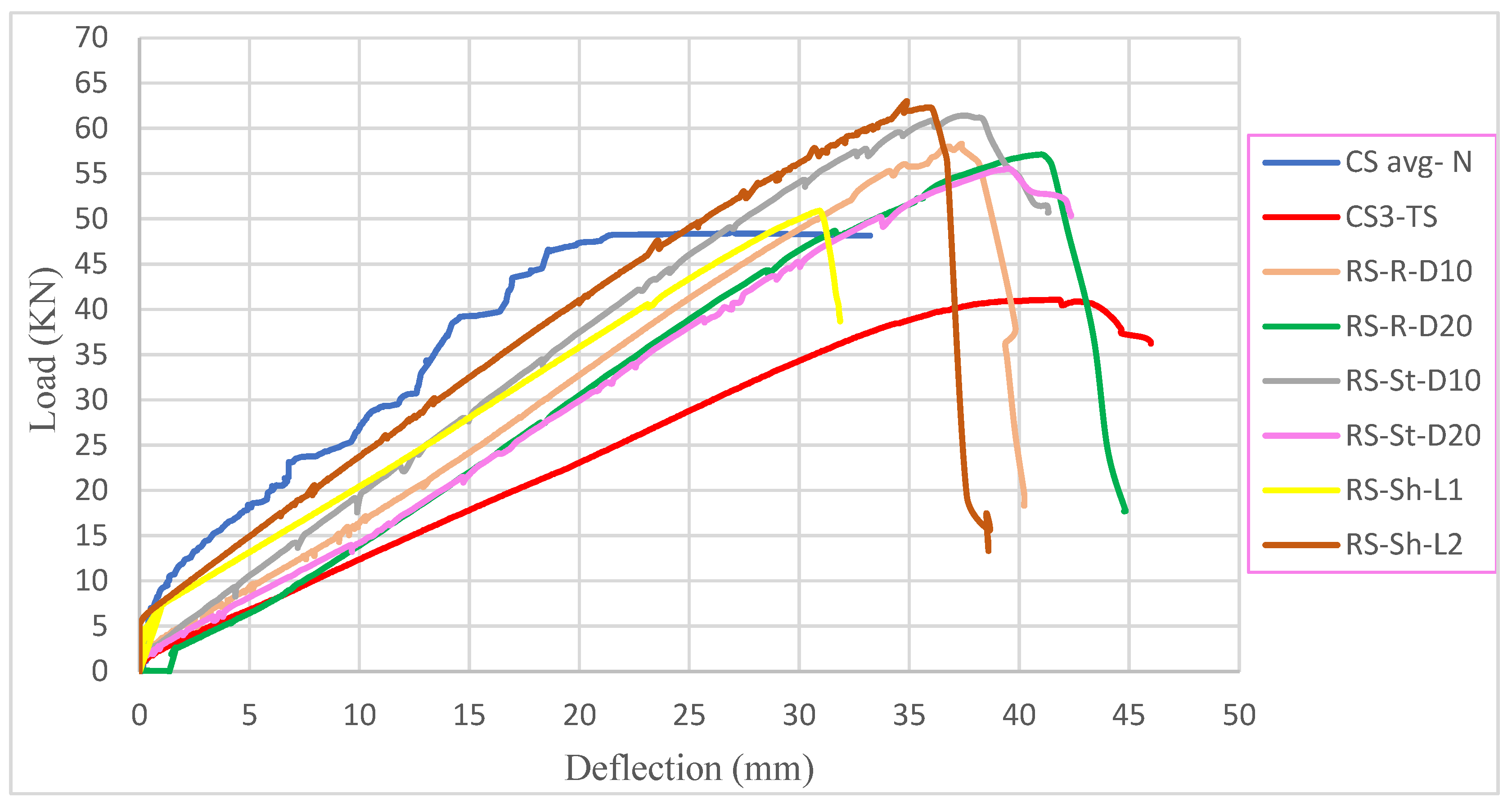
4.1. Load-Deflection Curve
4.2. Ultimate Load
4.3. Maximum Deflection
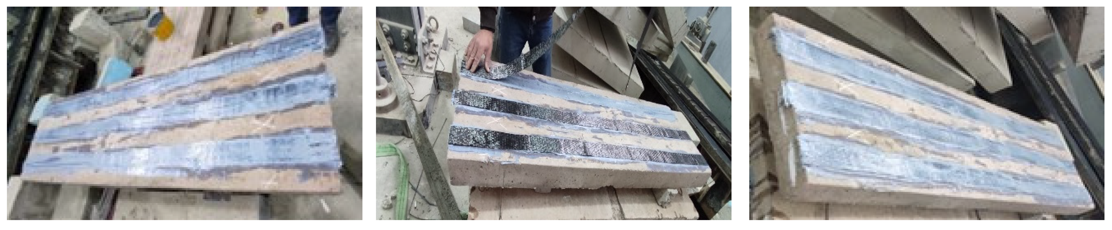
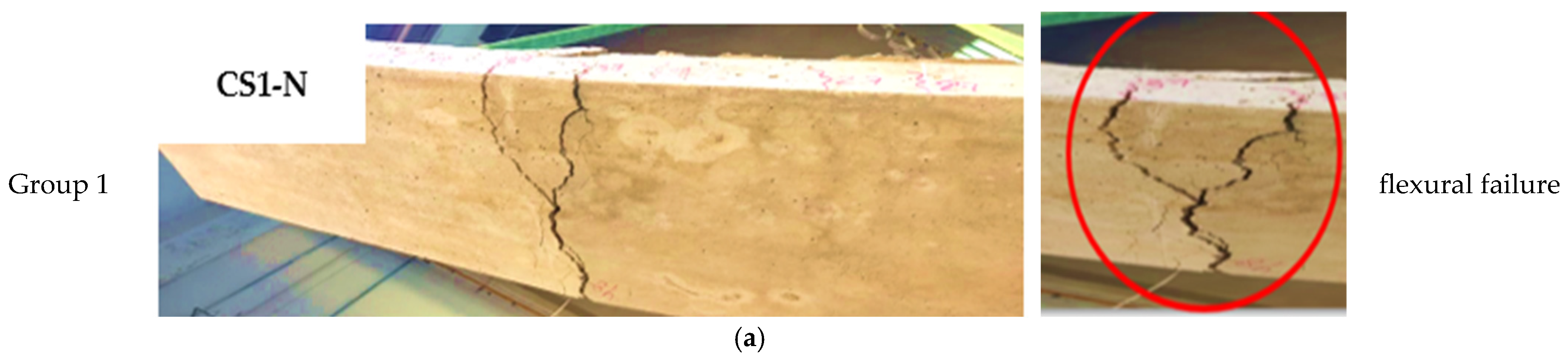
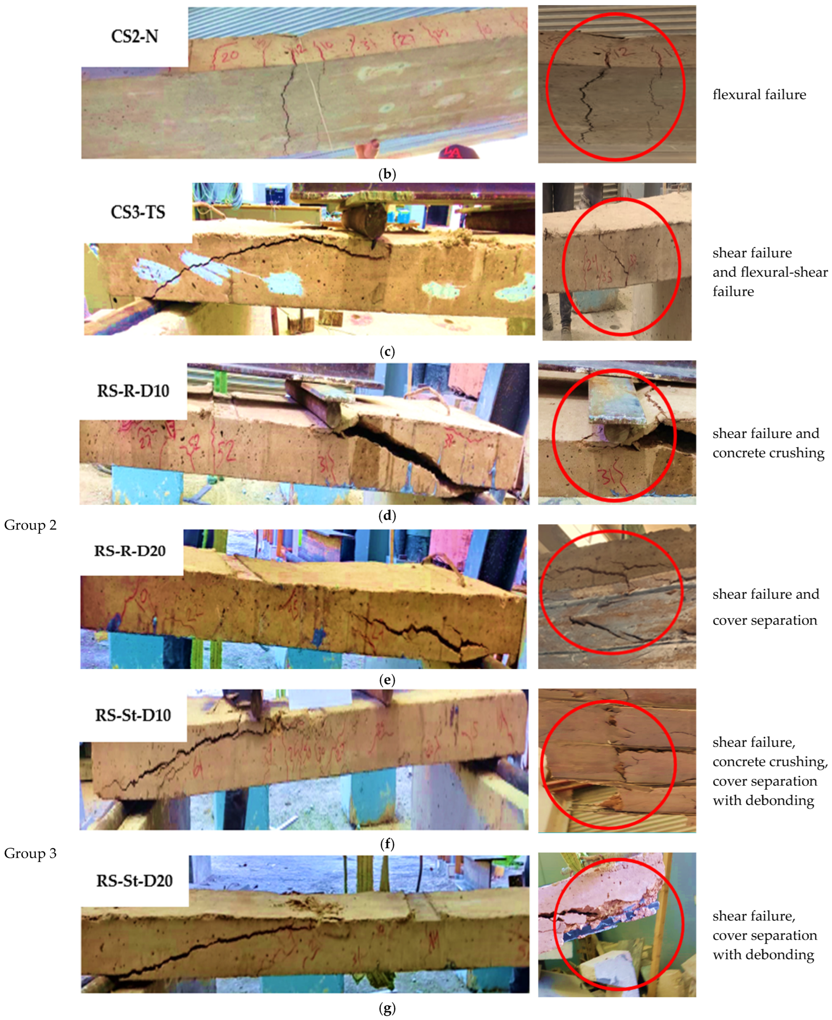
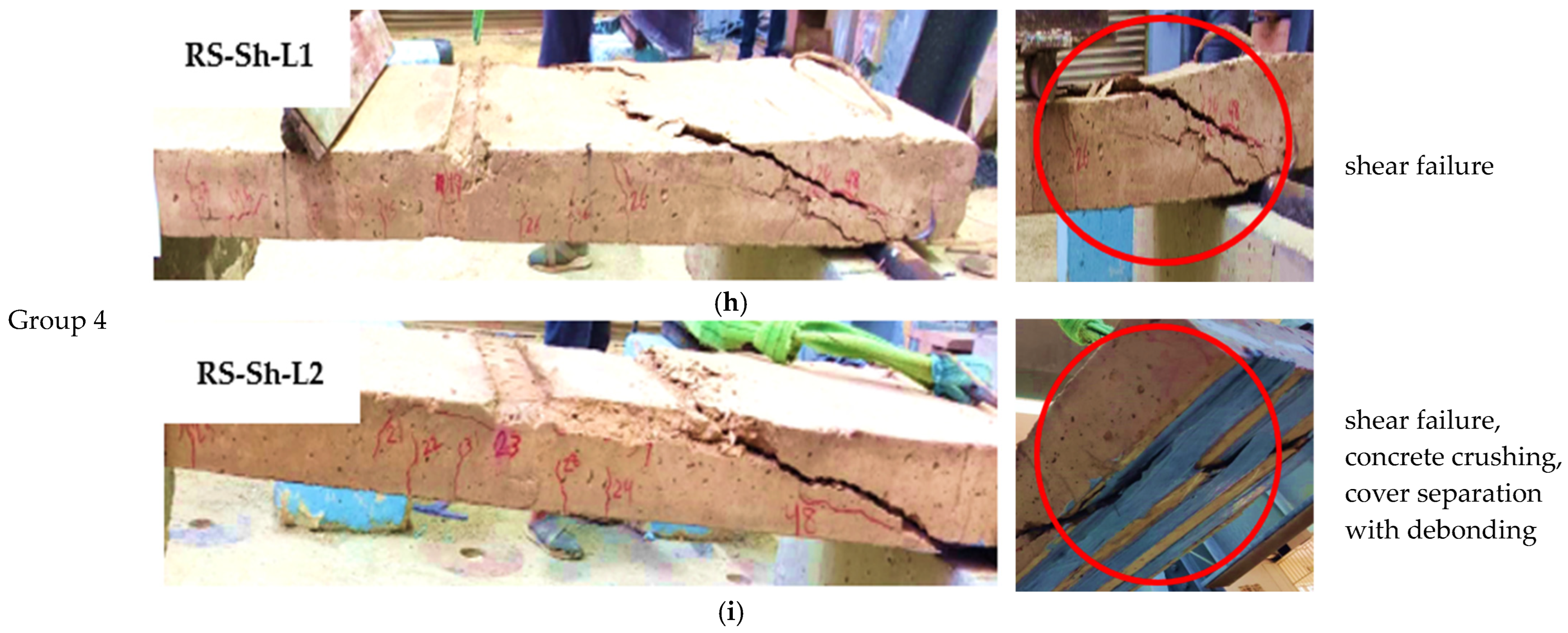
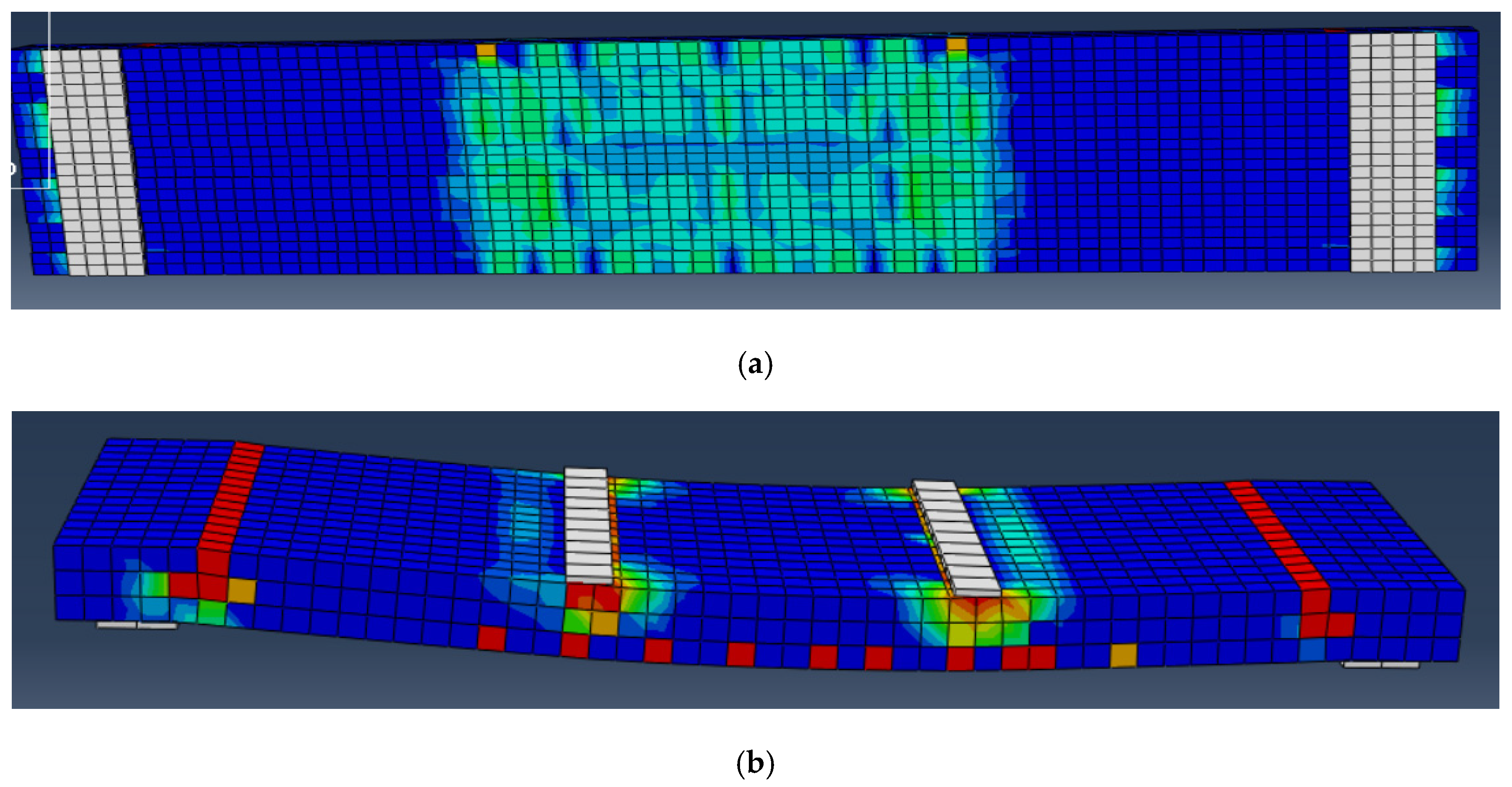
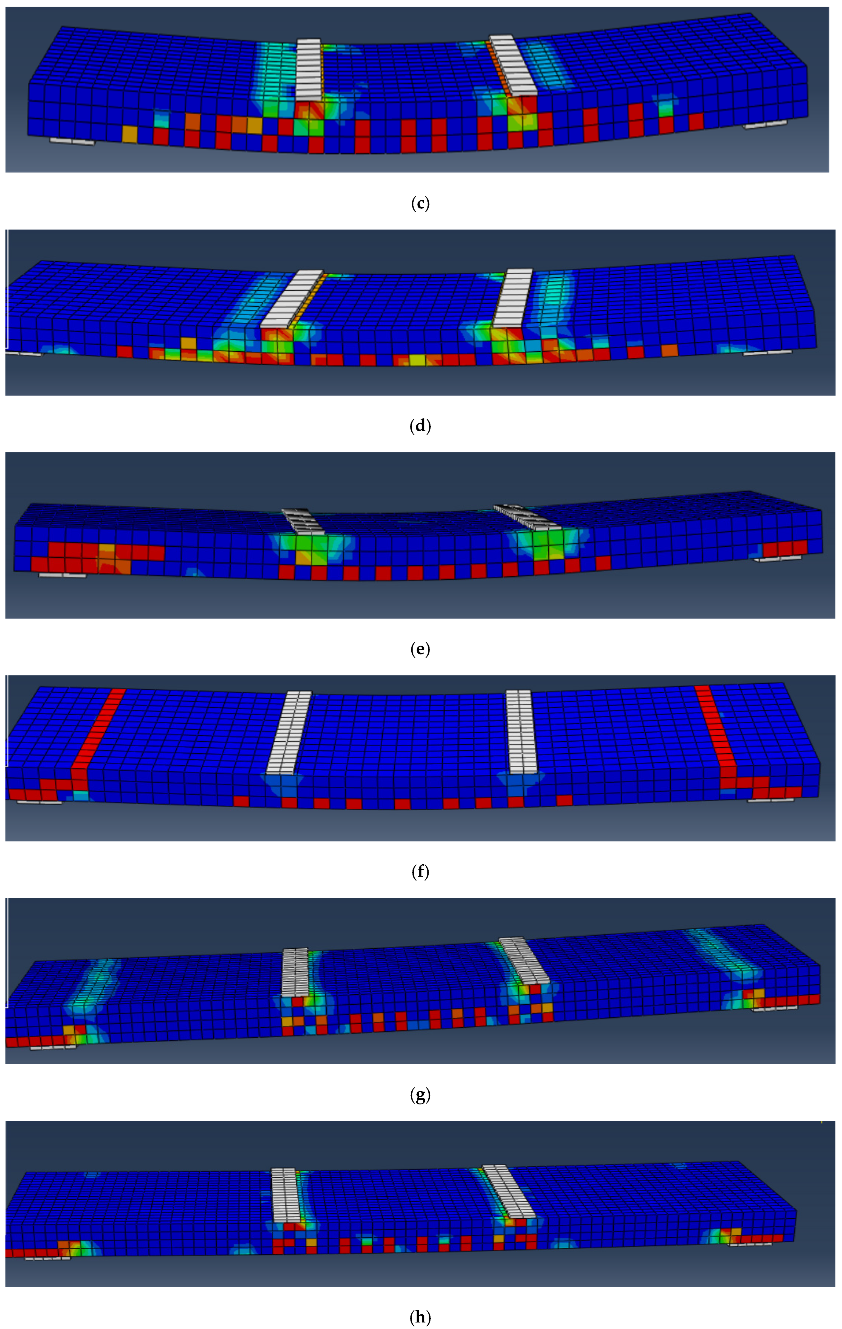
4.4. Failure Mode
4.5. Stiffness
4.6. Ductility Factor
4.7. Toughness
5. Discussion of Experimental Results
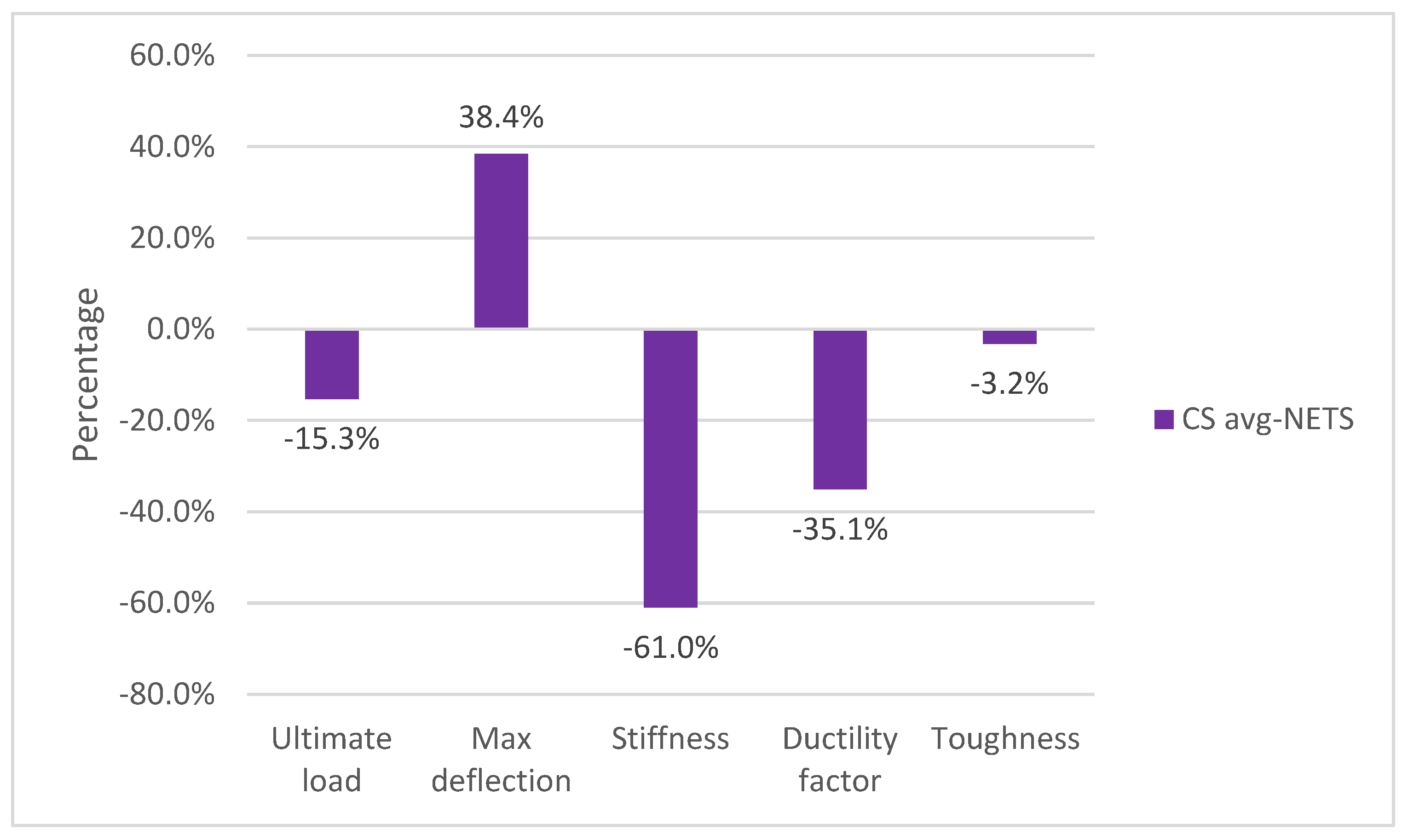
5.1. Impact of Thermal Shock (at 600 ℃)
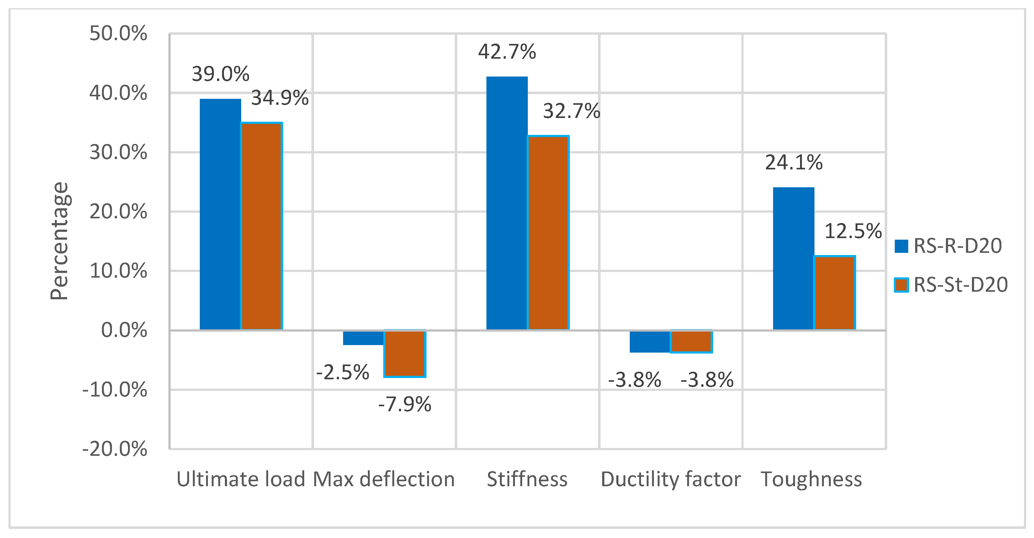
5.2. Impact of Spacing between CFRP Material
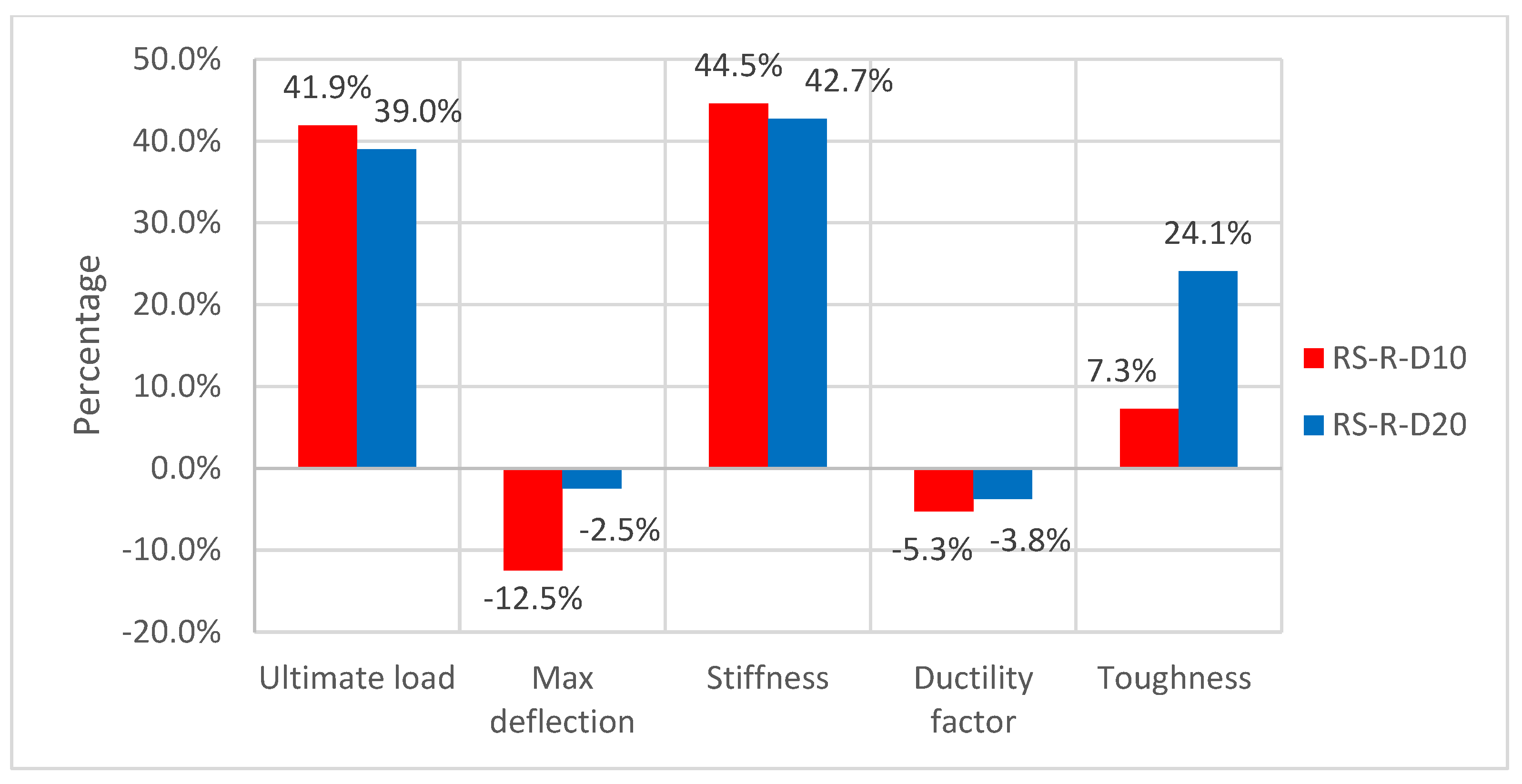
5.2.1. Impact of Spacing between Ropes
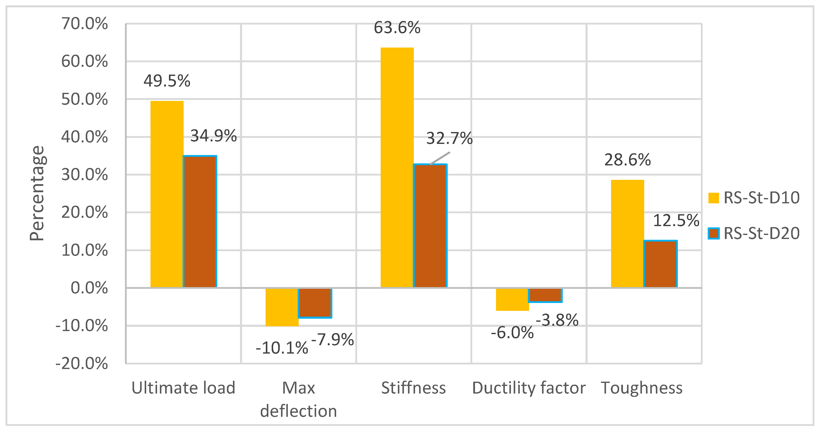
5.2.2. Impact of Spacing between Strips
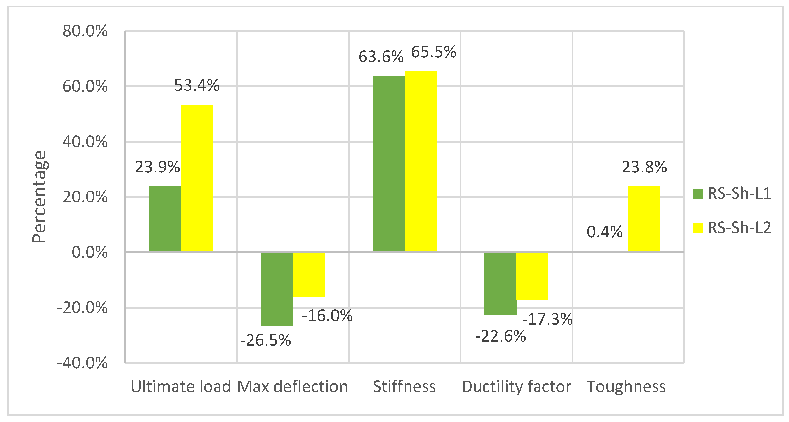
5.3. Impact of Number of Sheet Layers
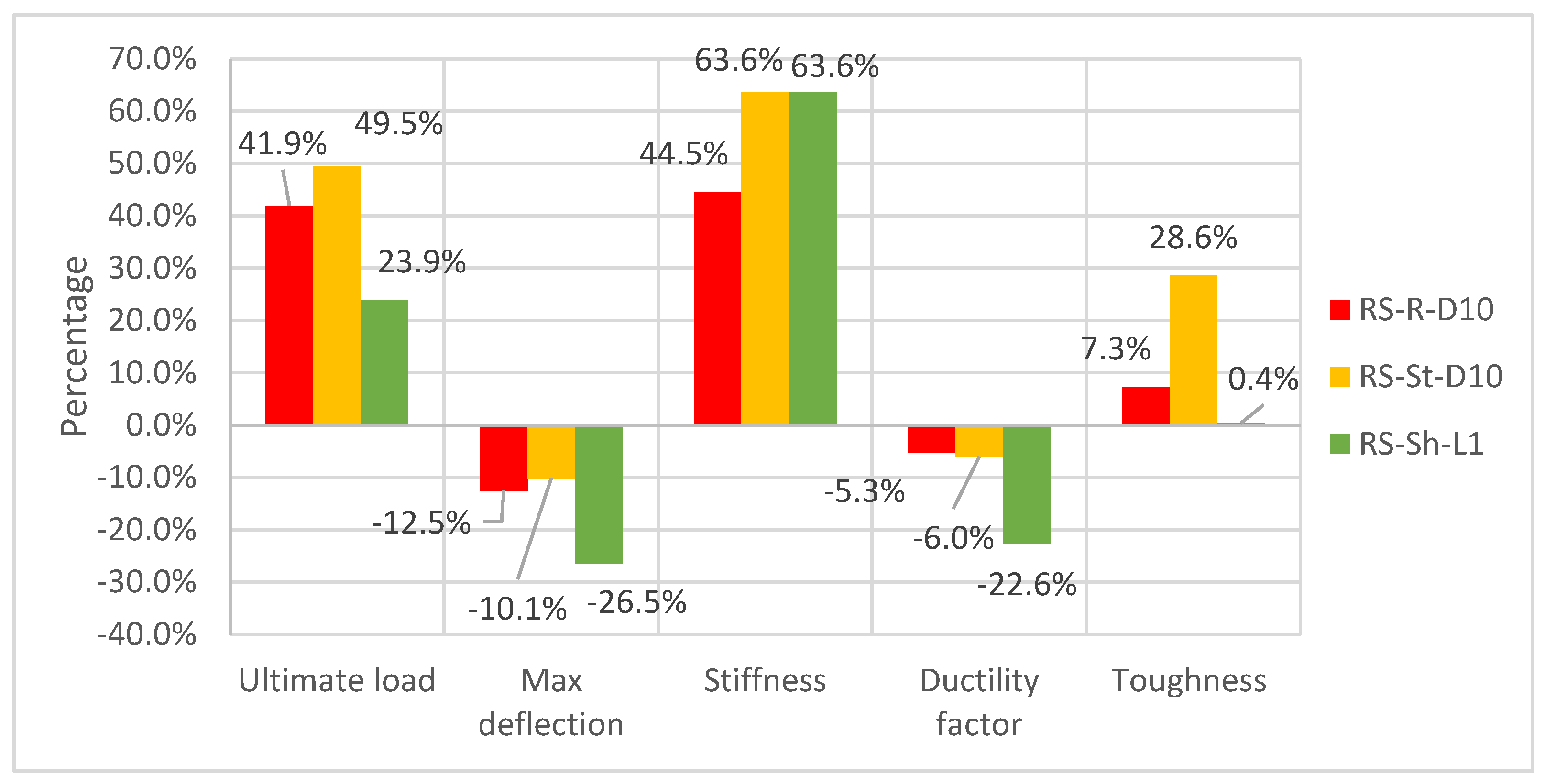
5.4. Impact of CFRP Form (Rope, Strip, Sheet)
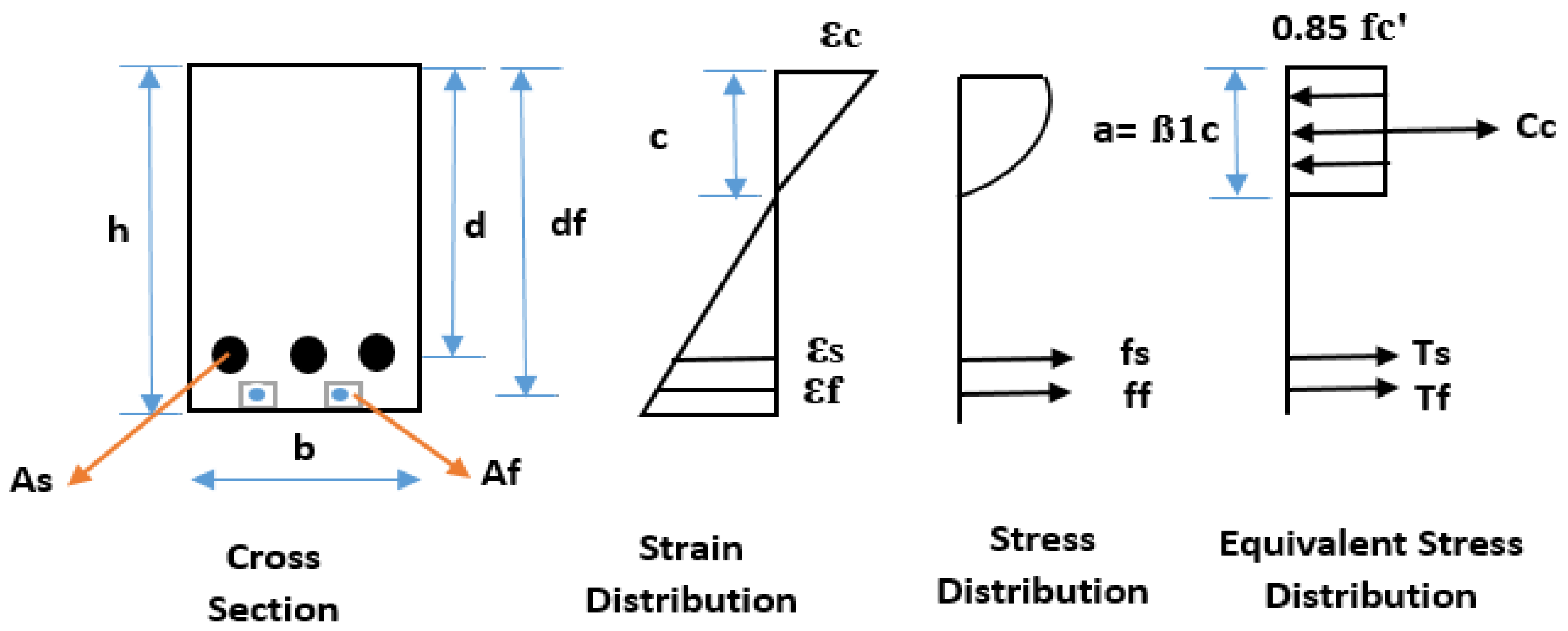
6. Analytical Results
7. Numerical Analysis
7.1. Finite Element Method (FEM)
7.2. Model Description
7.2.1. Parts
7.2.2. Materials
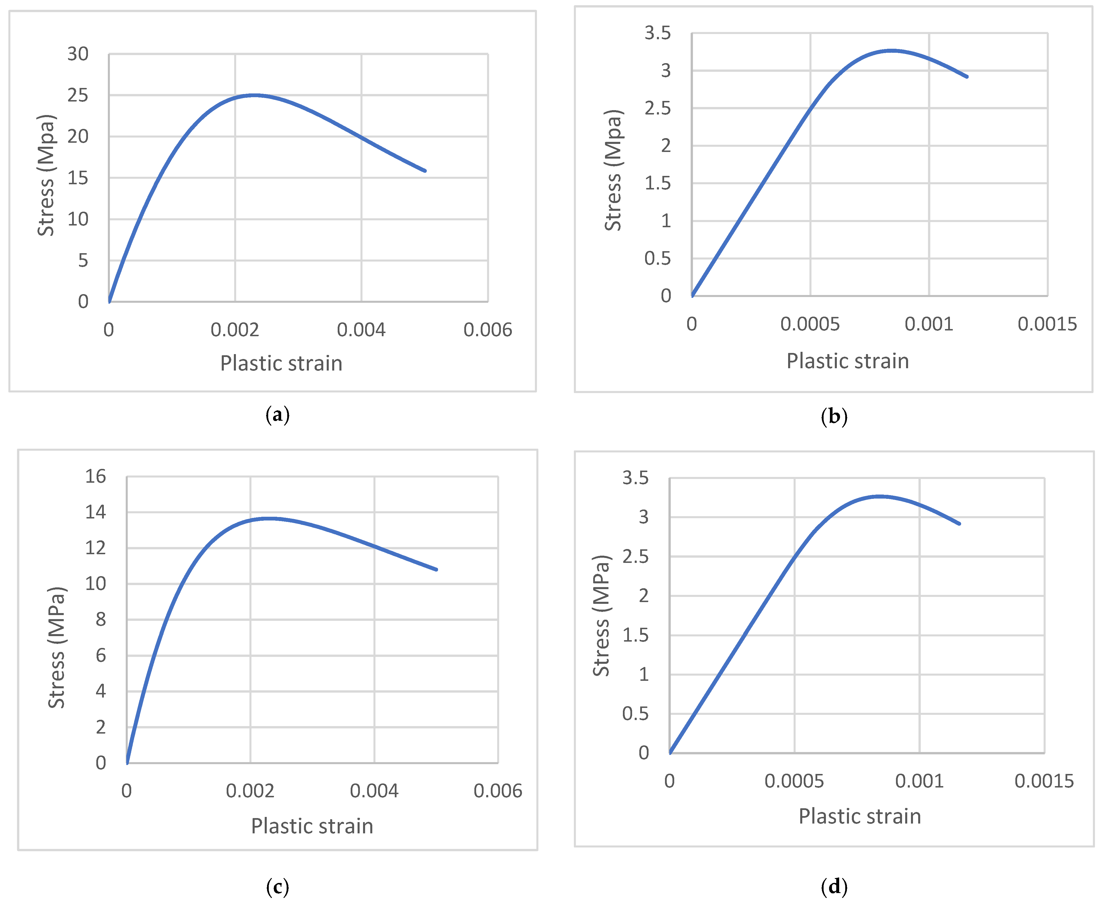
- Concrete
- Concrete Damage Parameter (CDP)
- σc: Concrete compressive stress along the descending stress–strain curve.
- f′ co: Concrete compressive stress at the peak point.
- σt: Concrete tensile stress along the descending stress–strain curve.
- f′ ct: Concrete tensile stress at the peak point.
- Steel reinforcement
- CFRP
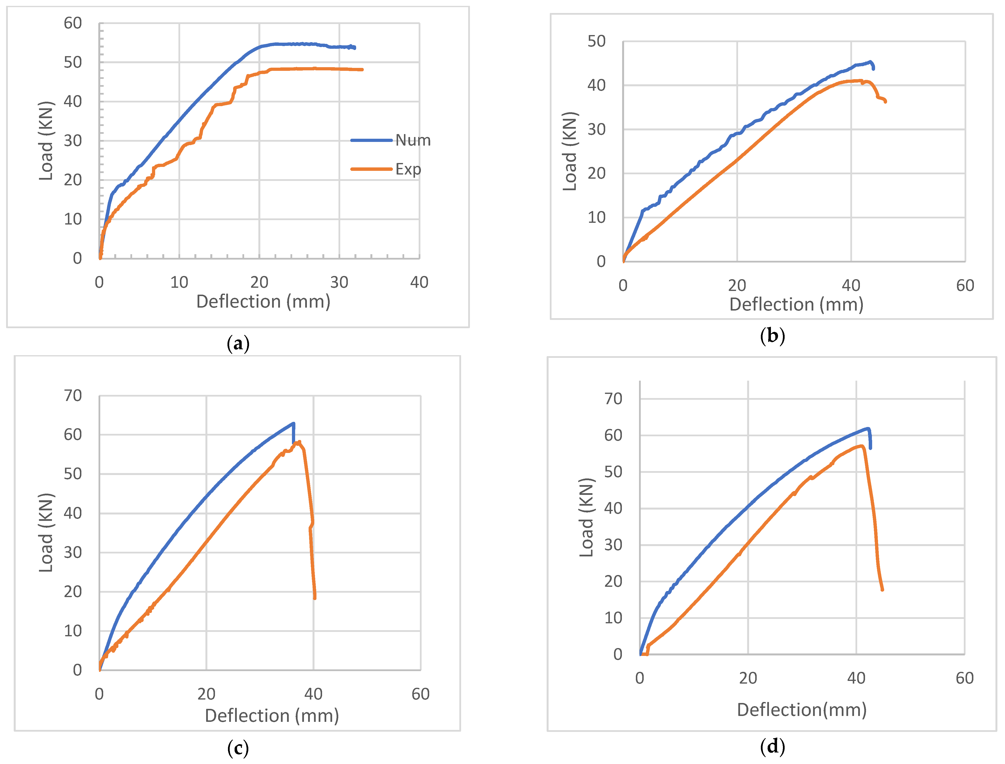
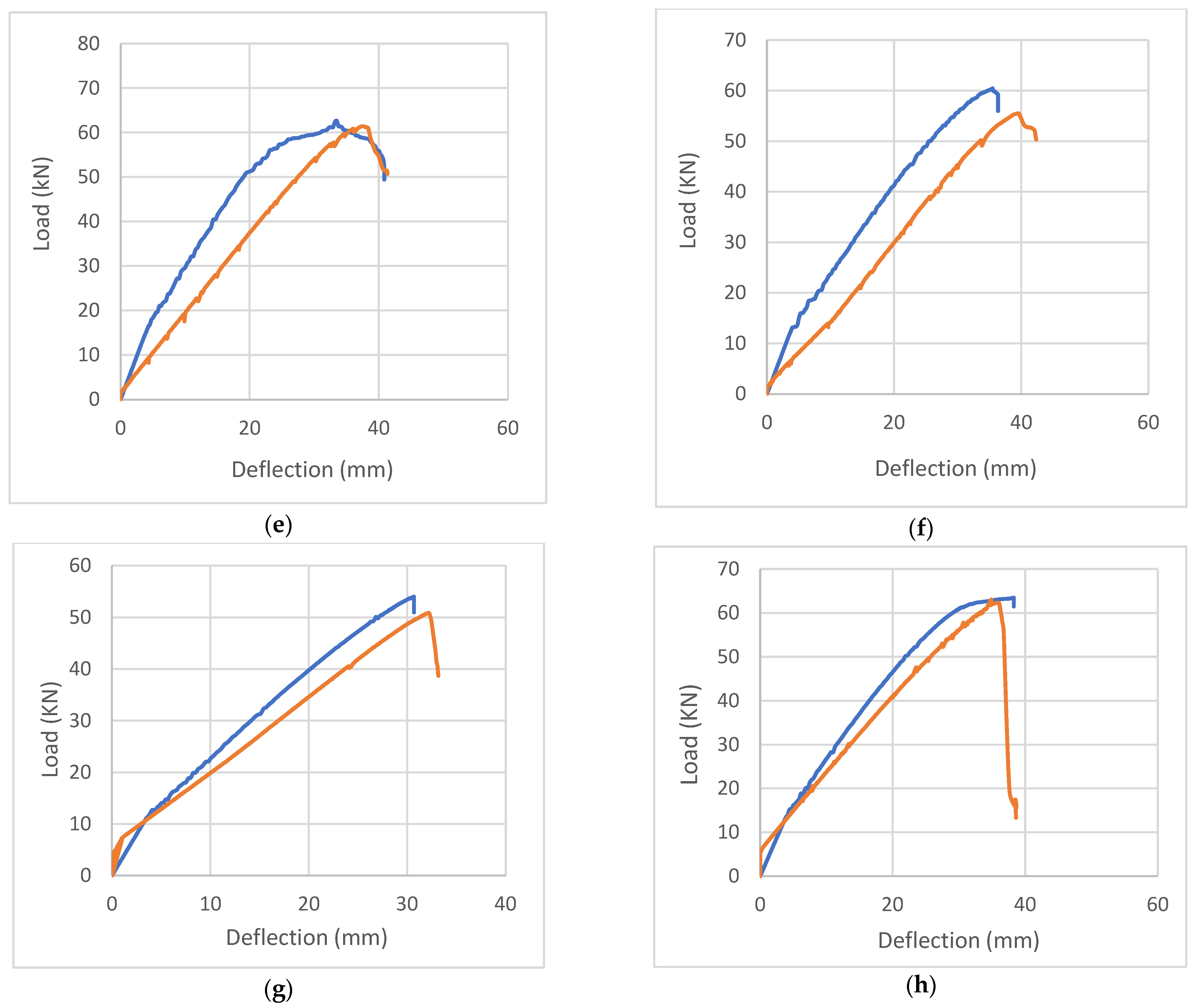
7.3. Numerical Results
8. Conclusions
- Exposure to thermal shock has an obvious and significant effect on mechanical properties. This effect is characterized by a decline in parameters such as compressive strength, elasticity, load capacity, toughness, and ductility.
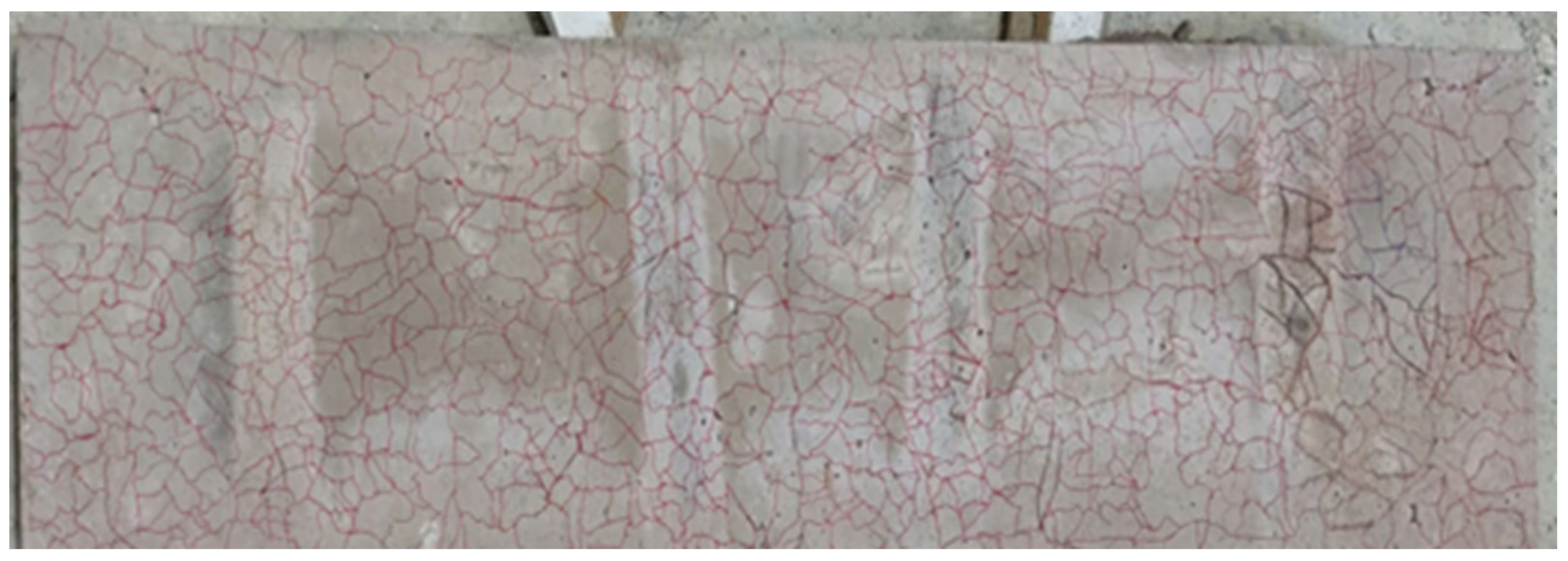
- Extensive cracks were observed to propagate across the concrete surface of thermally shocked slabs without spalling, a phenomenon attributed to water evaporation.
- The use of carbon fiber-reinforced polymer showed a noteworthy enhancement of the mechanical and structural properties of thermally shocked slabs, particularly in terms of load capacity, stiffness, toughness, and deflection.
- All rehabilitated slabs exhibited the ability to recover their initial capacity before being subjected to thermal shock. However, the repaired slabs were unable to regain their original stiffness, likely due to internal cracks.
- The utilization of carbon fiber-reinforced polymer led to a reduction in the ductility property of thermally shocked slabs, possibly due to the brittle nature of the material.
- This research demonstrated that decreasing the spacing between carbon fiber-reinforced polymer materials resulted in improved load capacity: 2.9% for ropes and 14.6% for strips. Similarly, stiffness increased by 1.8% for ropes and 29.9% for strips, with positive effects extending to deflection reduction. Similar enhancements were observed with an increase in the number of layers.
- Thermal shock may have a negative effect on the failure mode of the slab. In this research, it shifted from flexural failure to brittle shear failure.
- The theoretical analysis consistently demonstrated slightly superior performance compared to the experimental results. Therefore, it is advisable to incorporate a safety factor when evaluating the load capacity of a repaired slab.
- The finite element method stands out as a potent tool for replicating experimental tests, and its results can be extrapolated to investigate scenarios that have not been examined experimentally, requiring significant cost and time.
9. Recommendation and Future Work
- No studies have investigated the effect of using various types of FRP, such as GFRP.
- Temperature may play different roles in response and behavior; therefore, an in-depth understanding of the effect of temperature values and their correlations is needed.
- Conducting more research on various structural elements such as columns and two-way solid slabs.
- Using FRP with different configurations, such as orientation (45° and 90°), sheet widths (100 and 200 mm), CFRP rope and strip with different lengths, and more than one layer (2 and 3).
Author Contributions
Funding
Data Availability Statement
Conflicts of Interest
References
- Khan, Q.U.Z.; Ahmad, A.; Raza, A.; Labibzadeh, M.; Iqbal, M. Structural Performance of One-Way Slabs Reinforced with Steel and Polypropylene Fibers. J. Kejuruter. 2021, 33, 193–203. [Google Scholar] [CrossRef]
- Abdel-Jaber, M.; Shatarat, N.; Katkhuda, H.; Al-Zu’bi, H.; Al-Nsour, R.; Alhnifat, R.; Al-Qaisia, A. Influence of Temperature on Shear Behavior of Lightweight Reinforced Concrete Beams Using Pozzolana Aggregate and Expanded Polystyrene Beads. CivilEng 2023, 4, 1036–1051. [Google Scholar] [CrossRef]
- Faris, N.; Zayed, T.; Abdelkader, E.M.; Fares, A. Corrosion assessment using ground penetrating radar in reinforced concrete structures: Influential factors and analysis methods. Autom. Constr. 2023, 156, 105130. [Google Scholar] [CrossRef]
- Abdel-Jaber, M.; Shatarat, N.; El-Nimri, R. Influence of Using Expanded Polystyrene Beads on the Density and Compressive Strength of Hardened Concrete. Civ. Eng. Arch. 2023, 11, 3599–3611. [Google Scholar] [CrossRef]
- de Carvalho, E.F.T.; Neto, J.T.d.S.; Junior, P.R.R.S.; Maciel, P.d.S.; Fransozo, H.L.; Bezerra, A.C.d.S.; de Gouveia, A.M.C. Influence of cooling methods on the residual mechanical behavior of fire-exposed concrete: An experimental study. Materials 2019, 12, 3512. [Google Scholar] [CrossRef]
- Fehérvári, S. Effect of cooling methods on the residual properties of concrete exposed to elevated temperature. Results Eng. 2022, 16, 100797. [Google Scholar] [CrossRef]
- Abramowicz, M.; Kowalski, R. The influence of short time water cooling on the mechanical properties of concrete heated up to high temperature. J. Civ. Eng. Manag. 2005, 11, 85–90. [Google Scholar] [CrossRef]
- Obaidat, Y.; Barham, W.; Obeidat, R. Repair of thermally shocked reinforced concrete beams using near-surface mounted—Carbon fiber reinforced polymers ropes and strips. Constr. Build. Mater. 2023, 366, 130201. [Google Scholar] [CrossRef]
- Knyziak, P.; Kowalski, R.; Krentowski, J.R. Fire damage of RC slab structure of a shopping center. Eng. Fail. Anal. 2019, 97, 53–60. [Google Scholar] [CrossRef]
- Abdullah, A.; Al-Khazraji, S. Structural Behavior of High Strength Laced Reinforced Concrete One Way Slab Exposed to Fire Flame. Civ. Eng. J. 2019, 5, 2747–2761. [Google Scholar] [CrossRef]
- Abdel-Jaber, M.; Al-Nsour, R.; Shatarat, N.; Katkhuda, H.; Al-Zu’bi, H. Thermal Effect on the Flexural Performance of Lightweight Reinforced Concrete Beams Using Expanded Polystyrene Beads and Pozzolana Aggregate. Eng. Sci. 2023, 27, 1029. [Google Scholar] [CrossRef]
- Al-Zu’Bi, M.; Fan, M.; Al Rjoub, Y.; Ashteyat, A.; Al-Kheetan, M.J.; Anguilano, L. The effect of length and inclination of carbon fiber reinforced polymer laminates on shear capacity of near-surface mounted retrofitted reinforced concrete beams. Struct. Concr. 2021, 22, 3677–3691. [Google Scholar] [CrossRef]
- Al-Zu’Bi, M.; Fan, M.; Anguilano, L. Advances in bonding agents for retrofitting concrete structures with fibre reinforced polymer materials: A review. Constr. Build. Mater. 2022, 330, 127115. [Google Scholar] [CrossRef]
- Al-Zu’bi, H.; Abdel-Jaber, M.; Katkhuda, H. Flexural Strengthening of Reinforced Concrete Beams with Variable Compressive Strength Using Near-Surface Mounted Carbon-Fiber-Reinforced Polymer Strips [NSM-CFRP]. Fibers 2022, 10, 86. [Google Scholar] [CrossRef]
- Al-Zu’Bi, M.; Fan, M.; Anguilano, L. Composites Part C: Open Access Parametric investigation of flexural performance of concrete prisms retrofitted with near-surface mounted FRP bars. Compos. Part C Open Access 2023, 12, 100421. [Google Scholar] [CrossRef]
- Wang, Q.; Li, T.; Zhu, H.; Su, W.; Hu, X. Bond enhancement for NSM FRP bars in concrete using different anchorage systems. Constr. Build. Mater. 2020, 246, 118316. [Google Scholar] [CrossRef]
- Alexander, M.; Beushausen, H. Durability, service life prediction, and modelling for reinforced concrete structures—Review and critique. Cem. Concr. Res. 2019, 122, 17–29. [Google Scholar] [CrossRef]
- Abas Golham, M.; Al-Ahmed, A.H.A. Behavior of GFRP reinforced concrete slabs with openings strengthened by CFRP strips. Results Eng. 2023, 18, 101033. [Google Scholar] [CrossRef]
- Mohammed, S.A.; Said, A.M.I. Analysis of concrete beams reinforced by GFRP bars with varying parameters. J. Mech. Behav. Mater. 2022, 31, 767–774. [Google Scholar] [CrossRef]
- Sabbaghian, M.; Kheyroddin, A. Flexural strengthening of RC one-way slabs with high-performance fiber-reinforced cementitious composite laminates using steel and GFRP bar. Eng. Struct. 2020, 221, 111106. [Google Scholar] [CrossRef]
- Ayash, N.M.; Abd-Elrahman, A.M.; Soliman, A.E. Repairing and strengthening of reinforced concrete cantilever slabs using Glass Fiber–Reinforced Polymer (GFRP) wraps. Structures 2020, 28, 2488–2506. [Google Scholar] [CrossRef]
- Tan, K.Y.; Tumialan, G.; Nanni, A. Evaluation of Externally Bonded Cfrp Systems for the Strengthening of Rc Slabs. Fibre-Reinf. Polym. Reinf. Concr. Struct. 2003, 2, 417–426. [Google Scholar] [CrossRef]
- Niu, H.; Vasquez, A.; Karbhari, V.M. Effect of material configuration on strengthening of concrete slabs by CFRP composites. Compos. Part B Eng. 2005, 37, 213–226. [Google Scholar] [CrossRef]
- Elgabbas, F.; El-Ghandour, A.A.; Abdelrahman, A.A.; El-Dieb, A.S. Different CFRP strengthening techniques for prestressed hollow core concrete slabs: Experimental study and analytical investigation. Compos. Struct. 2010, 92, 401–411. [Google Scholar] [CrossRef]
- Saeed, Y.M.; Aules, W.A.; Rad, F.N. Flexural strengthening of RC columns with EB-CFRP sheets and NSM-CFRP rods and ropes. Compos. Struct. 2022, 301, 116236. [Google Scholar] [CrossRef]
- Seleem, M.; Megahed, F.; Badawy, A.; Sharaky, I. Performance of NSM and EB methods on the flexural capacity of the RC beams strengthened with reinforced HSC layers. Structures 2023, 56, 104950. [Google Scholar] [CrossRef]
- Hosseini, M.R.M.; Dias, S.J.E.; Barros, J.A.O. Behavior of one-way RC slabs flexurally strengthened with prestressed NSM CFRP laminates—Assessment of influencing parameters. Compos. Struct. 2020, 245, 112259. [Google Scholar] [CrossRef]
- Aghamohammadi, R.; Nasrollahzadeh, K.; Mofidi, A.; Gosling, P. Reliability-based assessment of bond strength models for near-surface mounted FRP bars and strips to concrete. Compos. Struct. 2021, 272, 114132. [Google Scholar] [CrossRef]
- Chen, J.; Teng, J. Shear capacity of FRP-strengthened RC beams: FRP debonding. Constr. Build. Mater. 2003, 17, 27–41. [Google Scholar] [CrossRef]
- Al-Saadi, N.T.K.; Mohammed, A.; Al-Mahaidi, R.; Sanjayan, J. A state-of-the-art review: Near-surface mounted FRP composites for reinforced concrete structures. Constr. Build. Mater. 2019, 209, 748–769. [Google Scholar] [CrossRef]
- Zhang, R.; Xue, X. A predictive model for the bond strength of near-surface-mounted FRP bonded to concrete. Compos. Struct. 2021, 262, 113618. [Google Scholar] [CrossRef]
- Sharaky, I.A.; Torres, L.; Comas, J.; Barris, C. Flexural response of reinforced concrete (RC) beams strengthened with near surface mounted (NSM) fibre reinforced polymer (FRP) bars. Compos. Struct. 2014, 109, 8–22. [Google Scholar] [CrossRef]
- Al-Nsour, R.; Abdel-Jaber, M.; Ashteyat, A.; Shatarat, N. Flexural repairing of heat damaged reinforced concrete beams using NSM-BFRP bars and NSM-CFRP ropes. Compos. Part C Open Access 2023, 12, 100404. [Google Scholar] [CrossRef]
- Ceroni, F.; Pecce, M.; Bilotta, A.; Nigro, E. Bond behavior of FRP NSM systems in concrete elements. Compos. Part B Eng. 2012, 43, 99–109. [Google Scholar] [CrossRef]
- da Costa, L.M.; Pires, T.A.d.C.; Silva, J.J.R. Shear strengthening of fire-damaged reinforced concrete beams using NSM CFRP laminates. Eng. Struct. 2023, 287, 116175. [Google Scholar] [CrossRef]
- De Lorenzis, L.; Teng, J.G. Near-surface mounted FRP reinforcement: An emerging technique for strengthening structures. Compos. Part B Eng. 2007, 38, 119–143. [Google Scholar] [CrossRef]
- Adheem, A.H.; Kadhim, M.M.; Jawdhari, A. Parametric study and improved capacity model for RC beams strengthened with side NSM CFRP bars. Structures 2022, 39, 1118–1134. [Google Scholar] [CrossRef]
- Jacobs, R.R.; Williams, C.S. Evaluation of flexural strengthening methods for beams with simulated deterioration using spike-anchored FRP externally bonded sheets and near-surface-mounted strips. Compos. Struct. 2023, 305, 116463. [Google Scholar] [CrossRef]
- Al-Rousan, R.Z. Anchored CFRP ropes for flexural capacity recovering of thermally damaged RC one-way slabs. Alex. Eng. J. 2023, 76, 757–774. [Google Scholar] [CrossRef]
- Al-Rousan, R. Behavior of strengthened concrete beams damaged by thermal shock. Mag. Civ. Eng. 2020, 2, 93–107. [Google Scholar]
- Assad, M.; Hawileh, R.A.; Abdalla, J.A. Modeling the behavior of CFRP-strengthened RC slabs under fire exposure. Procedia Struct. Integr. 2022, 42, 1668–1675. [Google Scholar] [CrossRef]
- Hamiruddin, N.A.; Razak, R.A.; Muhammad, K.; Zahid, M.Z.A.M. Repair of heat damaged reinforced concrete slab with High Strength Fibre Reinforced Concrete materials. In IOP Conference Series: Earth and Environmental Science; Institute of Physics Publishing: Bristol, UK, 2018. [Google Scholar] [CrossRef]
- Abdel-Jaber, M.; Abdel-Jaber, M.; Katkhuda, H.; Shatarat, N.; Sulaiman, A.; El-Nimri, R. Influence of Stirrup Spacing on the Strengthening and Rehabilitating of RC T-beams Using Near-Surface Mounted Carbon-Fiber-Reinforced Polymer Strips. Fibers 2022, 10, 103. [Google Scholar] [CrossRef]
- Gao, W.-Y.; Hu, K.-X.; Dai, J.-G.; Dong, K.; Yu, K.-Q.; Fang, L.-J. Repair of fire-damaged RC slabs with basalt fabric-reinforced shotcrete. Constr. Build. Mater. 2018, 185, 79–92. [Google Scholar] [CrossRef]
- Al-Rousan, R. Influence of opening sizes on the flexural behavior of heat-damaged reinforced concrete slabs strengthened with CFRP ropes. Case Stud. Constr. Mater. 2022, 17, e01464. [Google Scholar] [CrossRef]
- ACI 318M-19; Building Code Requirements for Structural Concrete. American Concrete Institute: Farmington Hills, MI, USA, 1989; Volume 2007.
- ISO, ISO 834-1:1999; Fire-Resistance Tests—Elements of Building Construction—Part 1, General Requirements. International Standard Organization: Geneva, Switzerland, 1999.
- Al-Khreisat, A.; Abdel-Jaber, M.; Ashteyat, A. Shear Strengthening and Repairing of Reinforced Concrete Deep Beams Damaged by Heat Using NSM–CFRP Ropes. Fibers 2023, 11, 35. [Google Scholar] [CrossRef]
- Houda, A.; Benbouras, M.; Zedira, H.; Redjel, B.; Lefilef, L. The Influence of Spacing Between Cfrp Strips on. Construction 2022, 13, 73–86. [Google Scholar]
- Al-Khafaji, A.; Salim, H. Flexural strengthening of RC continuous t-beams using CFRP. Fibers 2020, 8, 41. [Google Scholar] [CrossRef]
- Saadah, M.; Ashteyat, A.; Murad, Y. Shear strengthening of RC beams using side near surface mounted CFRP ropes and strips. Structures 2021, 32, 380–390. [Google Scholar] [CrossRef]
- ACI Committee 440; Guide for the Design and Construction of Externally Bonded FRP Systems for Strengthening Concrete ACI 440.2R-17. American Concrete Institute: Farmington Hills, MI, USA, 2017; p. 110.
- Pellegrino, C.; Modena, C. Fiber-reinforced polymer shear strengthening of reinforced concrete beams: Experimental study and analytical modeling. ACI Struct. J. 2006, 103, 720–728. [Google Scholar] [CrossRef]
- Sim, J.; Kim, G.; Park, C.; Ju, M. Shear strengthening effects with varying types of FRP materials and strengthening methods. Am. Concr. Institute ACI Spec. Publ. 2005, SP-230, 1665–1679. [Google Scholar] [CrossRef]
- Beramly, M.; Abdel-Jaber, M.; Katkhuda, H.; Shatarat, N.; Al-Diseet, M. Shear Strengthening and Rehabilitating of Reinforced Concrete T-Beams Using Externally Carbon Fiber Reinforced Polymer Sheets. J. Appl. Eng. Sci. 2022, 20, 498–510. [Google Scholar] [CrossRef]
- Yu, T.; Teng, J.; Wong, Y.; Dong, S. Finite element modeling of confined concrete-II: Plastic-damage model. Eng. Struct. 2010, 32, 680–691. [Google Scholar] [CrossRef]
- Abeje, Y.K. Numerical Study to Investigate the Effect of CFRP Sheet on Ductility of Reinforced Concrete Slab. Int. J. Eng. Res. Technol. 2022, 11, 142–153. [Google Scholar]
- Assad, M.; Hawileh, R.; Abdalla, J. Finite Element Simulation of FRP-Strengthened Thin RC Slabs. J. Compos. Sci. 2022, 6, 263. [Google Scholar] [CrossRef]
- CEN member, EN 1994-1-2 (2005); Eurocode 4: Design of Composite Steel and Concrete Structures—Part 1-2: General Rules—Structural Fire Design. ECS, European Committee for Standardization: Brussels, Belgium, 2011; Volume 1. (In English)
- Systèmes, D. Abaqus 6.12 analysis user’s manual: Prescribed conditions, constraints & interactions. Abaqus 2012, 5, 831. [Google Scholar]


| Characteristics | CFRP Type | ||
|---|---|---|---|
| Rope | Strip | Sheet | |
| Elasticit Modulus (GPa) | 240 | 165 | 230 |
| Tensile Strength (MPa) | 4000 | 3100 | 4900 |
| Fiber Density (g/cm3) | 1.82 | 1.6 | 1.8 |
| Cross Section (mm2) | 28 | 37.5 | 167/m width |
| Elongation at Break | ≥1.6% | ≥1.7% | 1.7% |
| Characteristics | Epoxy Type | |
|---|---|---|
| Sikandar®-330 | Sikandar®-52 LP | |
| Packaging | 5 kg A + B (light grey) | 4 kg A + B (Yellowish brownish) |
| Density (Kg/L) | 1.3 ± 0.1 | 1.06 |
| Tensile Strength (MPa) | 30 | 27 |
| Elastic Modulus (MPa) | 4500 | 1100 |
| Mixing Ratio | A:B = 4:1 part by weight | A:B = 2:1 part by weight and by volume |
| Elongation at Break | 0.9% | 1.9% |
| Symbol | Indicator |
|---|---|
| CS | Control Slab |
| RS | Repairing Slab exposed to thermal shock |
| N | Natural |
| TS | Thermal Shock |
| R | Rope |
| St | Strip |
| Sh | Sheet |
| D10 | Distance = 10 cm |
| D20 | Distance = 20 cm |
| L1 | One Layer |
| L2 | Two Layers |
| NO of Sample | Labeled | Exposure to Thermal Shock | Type of FRP | Parameter | Repair Configuration |
|---|---|---|---|---|---|
| 1 | CS1-N | Non | Non | Non | N/A |
| 2 | CS2-N | Non | Non | Non | N/A |
| 3 | CS3-TS | Exposed | Non | Non | N/A |
| 4 | RS-R-D10 | Exposed | Rope | Spacing (10 cm) | Rope at 10 cm |
| 5 | RS-R-D20 | Exposed | Rope | Spacing (20 cm) | Rope at 20 cm |
| 6 | RS-St-D10 | Exposed | Strip | Spacing (10 cm) | Strip at 10 cm |
| 7 | RS-St-D20 | Exposed | Strip | Spacing (20 cm) | Strip at 20 cm |
| 8 | RS-Sh-L1 | Exposed | Sheet | One Layer | One layer of sheet |
| 9 | RS-Sh-L2 | Exposed | Sheet | Two Layers | Two layers of sheet |
| Name | Ultimate Load (KN) | Max Deflection (mm) | Stiffness (KN/mm) | Ductility Factor | Toughness (KN.mm) | * Failure Mode |
|---|---|---|---|---|---|---|
| ** CS avg-N | 48.5 | 33.22 | 2.86 | 2.05 | 1200.58 | FF |
| CS3-TS | 41.08 | 45.98 | 1.1 | 1.33 | 1162.60 | SF and F-S |
| RS-R-D10 | 58.3 | 40.23 | 1.59 | 1.26 | 1247.02 | SF and CC |
| RS-R-D20 | 57.09 | 44.84 | 1.57 | 1.28 | 1442.48 | SF and CS |
| RS-St-D10 | 61.42 | 41.33 | 1.8 | 1.25 | 1494.92 | SF, CC, CS, and DF |
| RS-St-D20 | 55.43 | 42.36 | 1.46 | 1.28 | 1308.06 | SF, CS, and DF |
| RS-Sh-L1 | 50.88 | 33.8 | 1.8 | 1.03 | 1167.3 | SF |
| RS-Sh-L2 | 63 | 38.63 | 1.82 | 1.1 | 1439.19 | SF, CC, CS, and DF |
| Name | Ultimate Load (%) | Max Deflection (%) | Stiffness (%) | Ductility Factor (%) | Toughness (%) |
|---|---|---|---|---|---|
| CSavg-N | 18.1 | −27.8 | 160 | 54.1 | 3.23 |
| RS-R-D10 | 41.9 | −12.5 | 44.5 | −5.3 | 7.3 |
| RS-R-D20 | 39 | −2.5 | 42.7 | −3.8 | 24.1 |
| RS-St-D10 | 49.5 | −10.1 | 63.6 | −6 | 28.6 |
| RS-St-D20 | 34.9 | −7.9 | 32.7 | −3.8 | 12.5 |
| RS-Sh-L1 | 23.9 | −26.5 | 63.6 | −22.6 | 0.4 |
| RS-Sh-L2 | 53.4 | −16 | 65.5 | −17.23 | 23.8 |
| Name of Slab | Pn Exp (KN) | Pn Theo (KN) | Difference Ratio Compared with (Pn Exp) (%) | Deflection Exp (mm) | Deflection Theo (mm) | Difference Ratio Compared with (Deflection Exp) (%) |
|---|---|---|---|---|---|---|
| CSavg-N | 48.5 | 51.46 | 6.1 | 33.22 | 26.38 | −20.59 |
| CS3-TS | 41.08 | 42.83 | 4.26 | 45.98 | 38.59 | −16.07 |
| RS-R-D10 | 58.3 | 65.81 | 12.88 | 40.23 | 54.76 | 36.12 |
| RS-R-D20 | 57.09 | 59.62 | 4.43 | 44.84 | 53.63 | 19.6 |
| RS-St-D10 | 61.42 | 64.44 | 4.92 | 41.33 | 57.69 | 39.58 |
| RS-St-D20 | 55.43 | 58.81 | 6.1 | 42.36 | 52.07 | 22.92 |
| RS-Sh-L1 | 50.88 | 54.11 | 6.35 | 33.8 | 41.4 | 50.03 |
| RS-Sh-L2 | 63 | 63.05 | 0.07 | 38.63 | 59.18 | 53.2 |
| Part | Modeling Space | Element Type | Shape |
|---|---|---|---|
| Concrete | 3D | C3D8R: An 8-node linear brick, reduced integration, hourglass control. | Solid |
| Steel bars | 3D | T3D2: A 2-node linear 3D truss. | Wire |
| Load plate | 3D | C3D8R: An 8-node linear brick, reduced integration, hourglass control. | Solid |
| Support plate | 3D | C3D8R: An 8-node linear brick, reduced integration, hourglass control. | Solid |
| Rope | 3D | T3D2: A 2-node linear 3D truss. | Wire |
| Strip | 3D | S4R: A 4-node doubly curved thin or thick shell, reduced integration, hourglass control, finite membrane strains. | Shell |
| Sheet | 3D | S4R: A 4-node doubly curved thin or thick shell, reduced integration, hourglass control, finite membrane strains. | Shell |
| Material | Density | Elastic Modulus (Mpa) | Poisson’s Ratio |
|---|---|---|---|
| Rope | 1.82 × 10⁻⁹ | 240,000 | 0.2 |
| Strip | 1.6 × 10⁻⁹ | 165,000 | 0.2 |
| Sheet | 1.8 × 10⁻⁹ | 230,000 | 0.2 |
| Name of Slab | Ultimate Load Numerical (KN) | Max Deflection Numerical (mm) | Failure Mode |
|---|---|---|---|
| CSavg-N | 53.12 | 31.89 | FF |
| CS3-TS | 45.34 | 43.88 | SF |
| RS-R-D10 | 62.94 | 36.28 | SF |
| RS-R-D20 | 61.9 | 42.6 | SF |
| RS-St-D10 | 62.65 | 40.86 | SF |
| RS-St-D20 | 60.46 | 36.36 | SF |
| RS-Sh-L1 | 53.98 | 30.68 | SF |
| RS-Sh-L2 | 63.45 | 38.26 | SF |
| Name of Slab | Pn Compared to Experimental Results (%) | Max Deflection Compared to Experimental Results (%) | Pn Compared to Theoretical Results (%) | Max Deflection Compared to Theoretical Results (%) |
|---|---|---|---|---|
| CS avg-N | 9.54 | −4.01 | 6.42 | 20.87 |
| CS3-TS | 10.38 | −4.58 | 11.45 | 13.70 |
| RS-R-D10 | 7.96 | −9.83 | −4.36 | −33.75 |
| RS-R-D20 | 8.42 | −5 | 3.81 | −20.56 |
| RS-St-D10 | 2.01 | −1.14 | −2.78 | −29.17 |
| RS-St-D20 | 9.07 | −14.16 | 4.62 | −30.17 |
| RS-Sh-L1 | 6.09 | −9.2 | −0.24 | −35.81 |
| RS-Sh-L2 | 0.71 | −0.95 | 0.64 | −35.35 |
Disclaimer/Publisher’s Note: The statements, opinions and data contained in all publications are solely those of the individual author(s) and contributor(s) and not of MDPI and/or the editor(s). MDPI and/or the editor(s) disclaim responsibility for any injury to people or property resulting from any ideas, methods, instructions or products referred to in the content. |
© 2024 by the authors. Licensee MDPI, Basel, Switzerland. This article is an open access article distributed under the terms and conditions of the Creative Commons Attribution (CC BY) license (https://creativecommons.org/licenses/by/4.0/).
Share and Cite
Shhabat, M.; Ashteyat, A.; Abdel-Jaber, M. Repairing of One-Way Solid Slab Exposed to Thermal Shock Using CFRP: Experimental and Analytical Study. Fibers 2024, 12, 18. https://doi.org/10.3390/fib12020018
Shhabat M, Ashteyat A, Abdel-Jaber M. Repairing of One-Way Solid Slab Exposed to Thermal Shock Using CFRP: Experimental and Analytical Study. Fibers. 2024; 12(2):18. https://doi.org/10.3390/fib12020018
Chicago/Turabian StyleShhabat, Mousa, Ahmed Ashteyat, and Mu’tasim Abdel-Jaber. 2024. "Repairing of One-Way Solid Slab Exposed to Thermal Shock Using CFRP: Experimental and Analytical Study" Fibers 12, no. 2: 18. https://doi.org/10.3390/fib12020018