Review

Utilization of Novel Basalt Fiber Pellets from Micro- to Macro-Scale, and from Basic to Applied Fields: A Review on Recent Contributions

1
Department of Civil Engineering, Lakehead University, Thunder Bay, ON P7B 5E1, Canada
2
Military Institute of Science and Technology (MIST), Dhaka 1216, Bangladesh
3
Manitoba Transportation and Infrastructure, Government of Manitoba, Winnipeg, MB R3C 3P3, Canada
4
Department of Structural Engineering, Ain Shams University, Cairo 11517, Egypt
5
Tetra Tech, Winnipeg, MB R3B 0Y4, Canada
6
Department of Civil Engineering, University of Manitoba, Winnipeg, MB R3T 5V6, Canada
*
Author to whom correspondence should be addressed.
Fibers 2024, 12(2), 17; https://doi.org/10.3390/fib12020017
Submission received: 5 October 2023 / Revised: 19 January 2024 / Accepted: 29 January 2024 / Published: 5 February 2024
(This article belongs to the Collection Review Papers of Fibers)

Abstract

:
Fiber-reinforced cementitious composites (FRCC) are one of the leading engineering materials in the 21st century, as they offer proficiency in enhancing strength, ductility, and durability in structural engineering applications. Because the recently developed basalt fiber pellets (BFP) offer combined strands of fibers encased in a polymer matrix, they are being prevalently studied to explore new possibilities when used in brittle materials such as mortar and concrete. Hence, this paper synthesizes the intensive research efforts and contributions to this novel class of fibers conducted by the authors. Specifically, it reviews the fresh, mechanical, and durability properties of FRCC incorporating single BFP or hybrid with polyvinyl alcohol fibers and modified with slag/fly ash and nano-materials and its suitability for different field applications. In addition, the nano- and meso-scale modeling of such matrices are described. BFP significantly contributes to improving post-cracking flexural behavior by toughening the cementitious matrix and minimizing strength losses when exposed to harsh environments. All results show promising progress in the development of high-performance FRCC comprising BFP, with potential success for structural and pavement applications.

Graphical Abstract

1. Introduction

Conventional concrete is normally brittle and has low tensile strength and strain capacity. This technical limitation may result in a decrease in the performance and service life of concrete, as well as the nucleation and spread of cracks, especially in areas that are more susceptible, such as joints in pavement and bridges that are subject to extreme loading and environmental conditions like the presence of salt and moisture. Numerous studies have been conducted to mitigate the low toughness/ductility of conventional concrete [1,2,3,4]. As an outcome of various studies, short and randomly distributed discrete fibers (three-dimensional reinforcement) are used to address the issues related to concrete’s brittleness and poor resistance to crack initiation and growth. Engineering qualities like tensile strength, flexural strength, impact, fatigue, deformation capability, toughness, and load-bearing capacity after cracking are all significantly improved by fiber inclusion in the matrix [4,5,6,7,8,9].
Different types of fibers are being adopted by researchers to develop fiber-reinforced cementitious composites (FRCC), including synthetic, organic, inorganic, and metallic fibers. The fiber type, geometry, engineering properties, and its dosage affect their debonding and the post-crack behavior of concrete [10,11]. A newly developed fiber produced from basalt rocks is increasingly being researched for civil engineering applications due to its balanced mechanical qualities and affordable price. They are also easily accessible as basalt/volcanic rocks cover 70% of the surface of the earth [12,13]. Basalt fibers are produced from crushed basalt rocks that contain various minerals, including olivine, pyroxene, and plagioclase. To manufacture basalt fiber filaments, basalt rock is cleaned, melted to 1400 °C, and then ejected through small nozzles to make them appropriate for replacing asbestos. The diameter range of the basalt fiber filaments is 9 to 13 μm. The manufacturing process is very challenging due to the higher melting temperature of the rocks. However, the energy requirement for the manufacturing process is smaller, about forty times less than carbon fiber and three times less than steel fiber production [14,15]. The basalt fibers production process does not produce any environmental by-product waste, as it is biodegradable and non-toxic. Additionally, no hazardous materials or chemical additives are needed for their production [13]. This kind of fiber is non-corrosive and environmentally safe, with good thermal endurance and insulating characteristics [16,17,18]. Several research papers reported that conventional steel reinforcement can be replaced by adopting fiber-reinforced concrete with basalt [16,19,20]. They also have very strong interfacial bond with concrete matrix [21,22]. This fiber is believed to revolutionize the concrete industry owing to its low price, green effect, and due to it being lightweight, as well as eliminating the problem of corrosion that happens to metallic fibers [23,24,25,26].
Basalt fiber significantly improves the compressive, tensile, flexural, and impact strength of concrete [12,27,28,29,30,31,32]. Numerous studies have been carried out to examine the impact of basalt fiber on mechanical, structural, and physical qualities to establish a solid foundation for a few other applications such as pavements, parking structures, bridge decks, etc. Basalt fiber loses its bond strength with the cement matrix because of the reduction in the integrity and strength of the reinforced composites caused by the reaction between the alkaline pore solution and the silica component in basalt fibers [33]. To prevent this issue, these fibers are coated with a polymeric resin (such as epoxy or polyamide), which is called basalt fiber pellets (BFP). Polyamide provides chemical stability in alkaline media, which helps to minimize the negative effect of the alkaline cementitious system (pH value > 11) on the fiber component [34]. Figure 1 represents the reinforcing basalt fiber pellets. Compared to other forms of fibers like glass fibers or carbon fibers, the manufacturing process of basalt fibers is less expensive and more environmentally friendly. Additionally, basalt fiber pellets have moderate elastic modulus (93–110 GPa), high tensile strength (3000–4000 MPa), and are highly heat resistant to corrosion, in contrast to steel fibers [24,35,36]. This type of fiber compensates for most of the problems that are created when using conventional concrete. Hence, they may present an attractive candidate for FRCC. They disclosed better mechanical properties than some other fibers such as E-glass and polypropylene fibers [37,38]. The highest compressive strength was found to be attained at a fiber content of 0.1%, while the toughness improved as the fiber content rose [39]. This type of fiber pellets also provide the cement composites with a better anti-dropping effect, a higher energy requirement for thermal decomposition, and reduce the speed of fire propagation [38].
Thus, there was extensive research that was initiated at the University of Manitoba to investigate the behavior of the basalt fiber pellets based on two main perspectives: the material and the structural performance, from the micro- to macro-scale and from the basic concepts to applications stage. This extensive research work started in 2015 and then continued until 2023 when the outcomes were published in several journal articles and conference papers. Thus, the present study is a review that synthesizes such contributions in the domain of this novel class of fibers.

2. Methodology

2.1. Overview

Since fibers are becoming popular for their exceptional characteristics when combined with concrete, extensive research has been undertaken to understand their behavior more elaborately. Basalt fiber stands out from all other fibers on account of its exceptional tensile strength of 3000–4000 MPa and moderate modulus of elasticity between 93 and 110 GPa [24,40]. Hence, this review paper presents an extensive assessment of basalt-fiber-reinforced cementitious composites in terms of mechanical and durability properties and their suitability for structural application. The framework of this study is divided into five phases, as depicted in Figure 2. Phase I focused on the material characterization and the fibrous concrete microstructure analysis; Phase II assessed the fresh and mechanical properties of the basalt-fiber-reinforced cementitious composites in terms of compressive strength, flexural strength, behavior under impact load, and pull-out test of single fiber pellet; Phase III evaluated the long term performance of such when exposed to harsh environment such as cyclic freeze–thaw and wet–dry environment, alkaline and salt–frost medium; Phase IV assessed the potential of using the proposed composites for structural application by studying the bond behavior with regular concrete, the bond/interaction with reinforcing bar and their aptitude to be used in large-scale structural element; and Phase V evaluated the suitability of basalt fiber as hybrid fiber when combined with polyvinyl alcohol fiber.

2.2. Materials

General use (GU) cement (ASTM Type I), along with some other cementitious materials, was adopted in this project to produce the base binder of the composite. Ground granulated blast furnace slag of grade 100 and fly ash were used at 40–50% and 50%, respectively, as a substitute for cement to refine the concrete matrix. Generally, these supplementary cementitious materials (SCMs) improve the properties of cementitious matrix as they produce calcium–silicate–hydrate (C-S-H) gel as a result of their reaction with calcium hydroxide (CH), which optimizes the pore structure [41]. All the cementitious materials adopted in this project complied with the CSA A3001-18 [42] requirements. Table 1 represents the chemical and physical properties of the cementitious materials that have been provided by the manufacturers. Additionally, a commercially available nano-silica (Ns) aqueous solution with 50% solid content of SiO2 particles was added to the binder at a dosage of 6% by mass of the base binder. The addition of a small dosage of Ns can significantly accelerate the cement hydration and enhance the microstructural growth of cement-based materials [43]. Locally available fine aggregate (fineness modulus of 2.9 and a gradation of 0 to 600 μm), in compliance with ASTM C136 [44], was employed to prepare the mixtures. A special form of basalt fiber is basalt fiber pellets (BFP), which are made of basalt fibers encapsulated by polyamide or other resins to alleviate the low alkaline resistance. The BFPs, with a length of 36 mm and a diameter of 1.8 mm, were used to reinforce the cementitious composites. When these materials are mixed with fibers, a high-performance nano-modified fiber-reinforced cementitious composite (NFRCC) is produced. However, the presence of Ns increased the friction between the components in the plastic, necessitating high dosages (6 to 11 L/m3) of a polycarboxylic acid-based high-range water-reducing admixture (HRWRA) that complies with ASTM C494 [45] Type F.

2.3. Test Parameters

To comprehensively analyze the effect of BFP on NFRCC, three different volumetric percentages of BFPs have been adopted, which are 2.5%, 4.5%, and 6.9%. The amount of nano-silica has been kept constant at 6% throughout this project. The percentage of the SCMs (slag or fly ash) adopted in this study was varied to replace GU cement by 40% and 50% to evaluate their influence on the NFRCC. The water-to-binder (w/b) ratio was maintained at 0.30. Reference mixtures have also been adopted for each type of SCM without BFP content to compare the influence of BFPs on NFRCC. The detail of the test parameters for each of the specimens is depicted in Table 2. For the mixture coding, the first part refers to the type and the replacement level of the SCM within the cementitious composite (“S” for slag-based composites and “F” for fly ash-based composites), whereas the second part denotes the fiber type and the fiber dosage used (“B” for basalt fiber pellet).

3. Results and Discussions

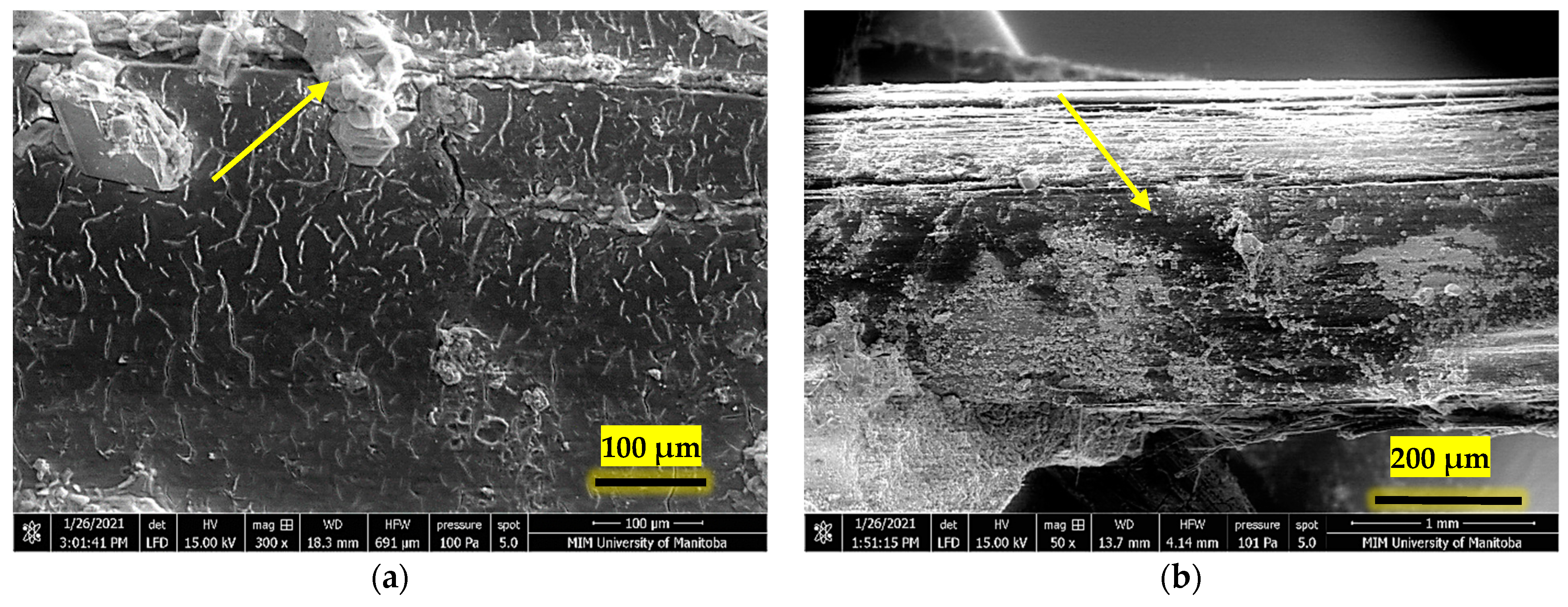
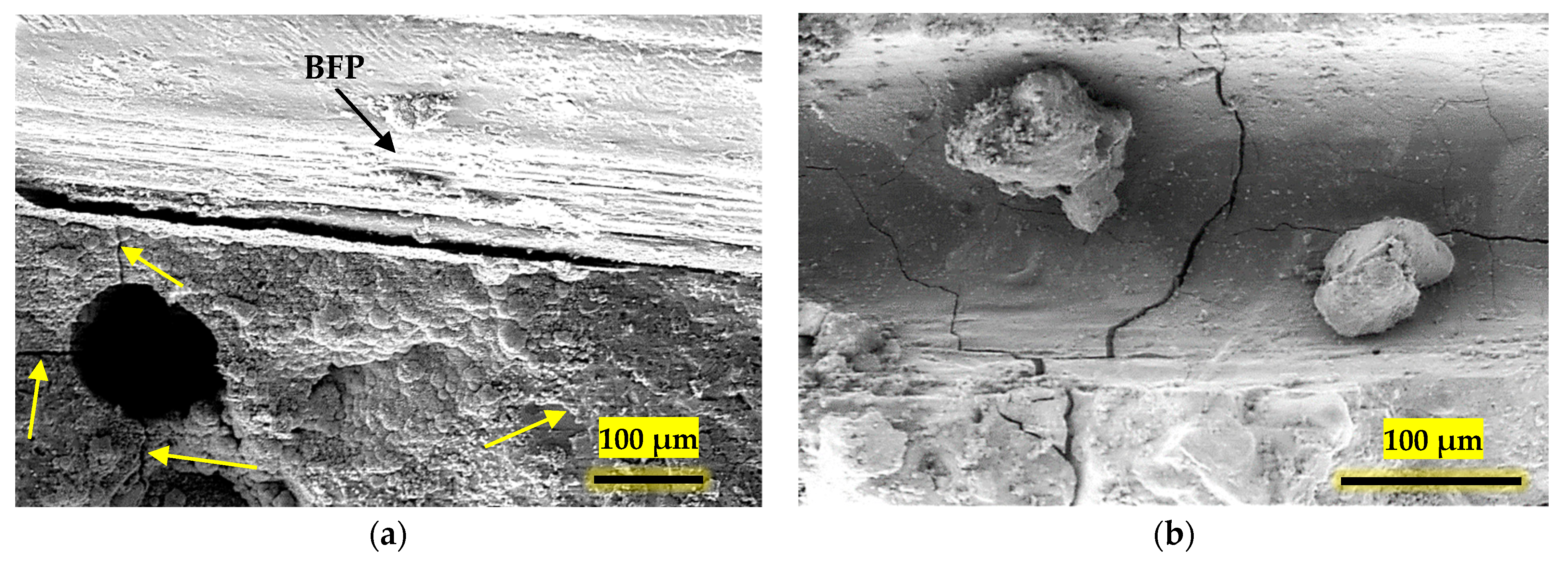
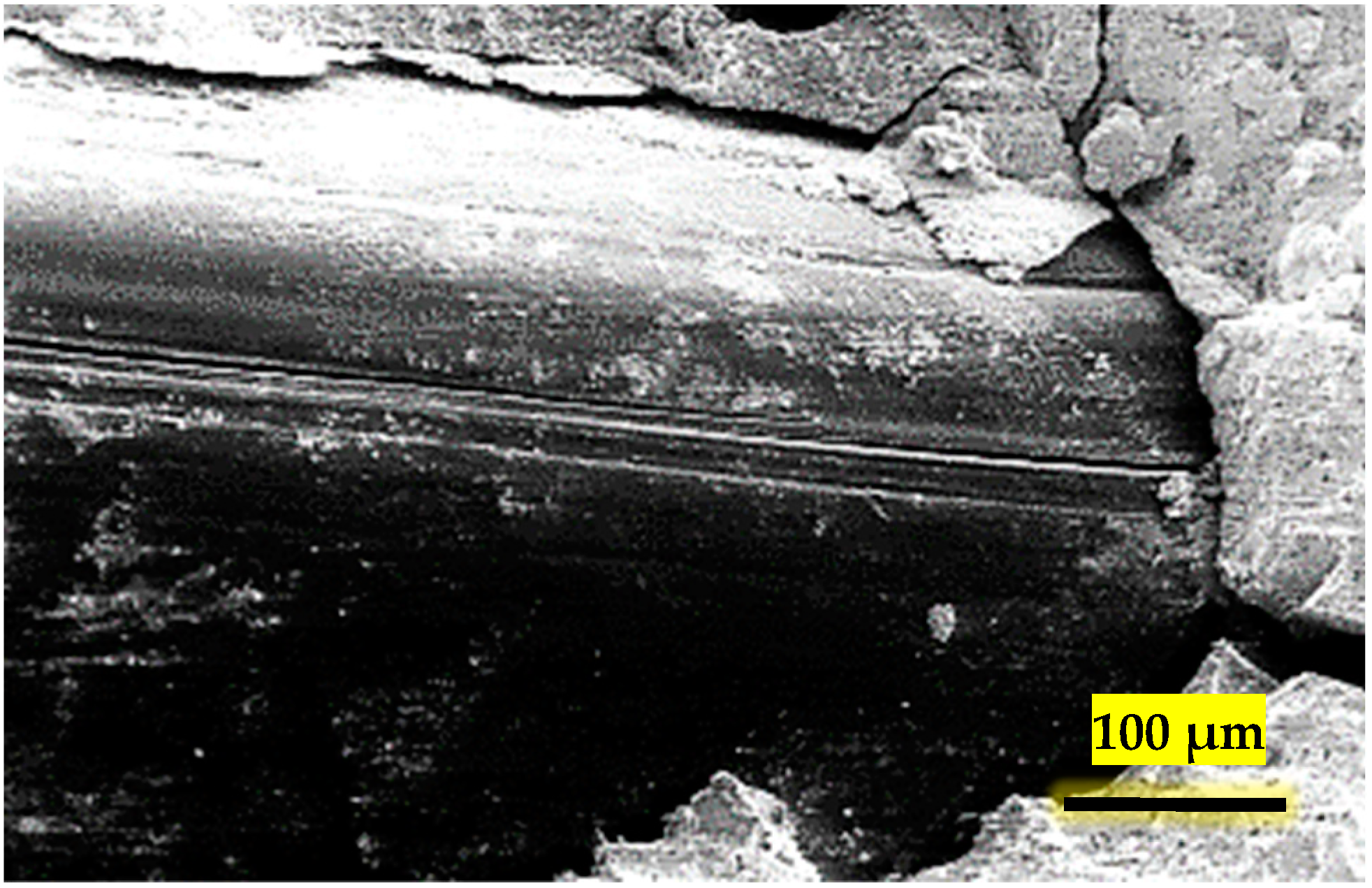
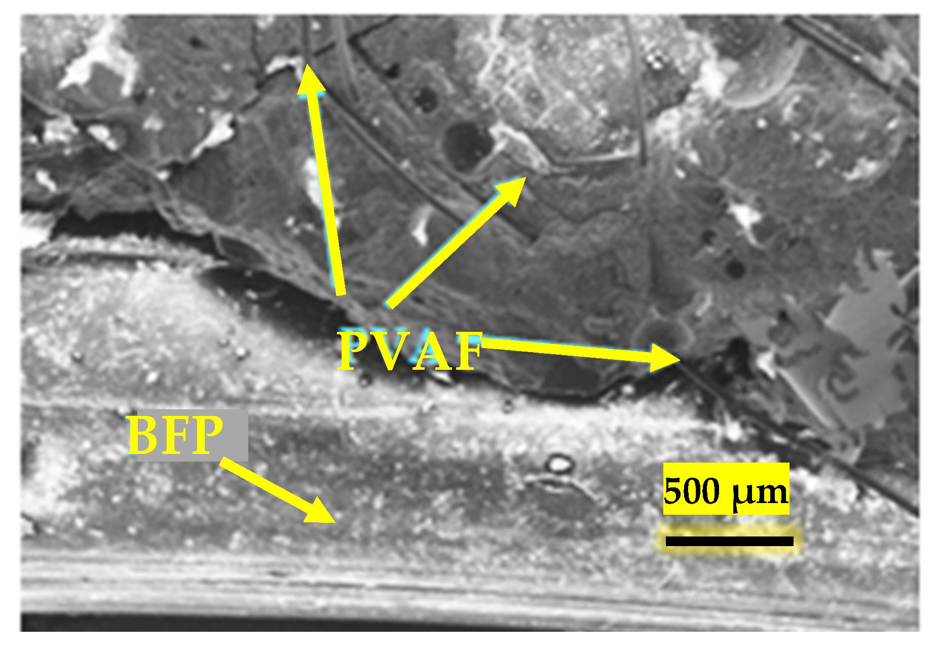
3.1. Phase I (Microstructural Analysis)

Microstructure analysis aids in determining the gradual change and eventual strength gain of the concrete matrix. When the microstructure of the NFRCC was analyzed, substantial consumption of the CH was found by Bediwy et al. [40] in the mixture containing 40% slag and 6% Ns when compared to the control mixture without SCMs at 28 days. This is because the presence of Ns catalyzed the slag’s reactivity within the cementitious matrix, which led to a greater degree of hydration and the development of microstructure. The ultrafine nature and the pozzolanic reactivity of Ns significantly accelerates the cement hydration kinetics by providing more surfaces for the deposition of the hydration products, which eventually improves the microstructure of concrete at early age [46]. According to Azzam et al. [47], after 28 days of curing, the 50% slag-based matrix had a more uniform and dense microstructure in contrast to the 50% fly-ash-based matrix, which contained a large number of unreacted fly ash particles in the matrix. The authors also found that for the slag-based matrix, the average Ca/Si (calcium/silicon) for the C-S-H gel was 1.17 in the interfacial transition zone (ITZ), indicating an effective rapid pozzolanic reaction that led to the densification of the ITZ with secondary C-S-H. On the other hand, for the fly-ash-based matrix, the average Ca/Si was lower at 1.32 due to its slower reaction time compared to slag. It was disclosed by Detwiler et al. [48] that the secondary C-S-H resulting from pozzolanic reactions has a lower Ca/Si ratio of 1.1 in comparison to the typical C-S-H produced by the cement hydration reaction with 1.7. This is why when the BFP is added to the mixtures, fly-ash- and slag-based composites exhibit dense matrix and ITZ between the fiber and the cement paste.
Figure 3 shows the scanning electron microscopy (SEM) image of the surface morphology of F50-B4.5 and S50-B4.5 specimens addressing the fiber–matrix interaction and the synergic effect of Ns with slag and fly ash observed by Azzam et al. [47] after 28 days. Longitudinal grooves on the BFP surface created an interlocking effect where the contact area was increased for additional growth and deposition of the hydration products, which strengthened the bond interface between the fiber and matrix. This phenomenon aided in improving the post-cracking performance of the composites, especially for higher BFP dosages (4.5% and 6.9%). Furthermore, the micrographs showed no evidence of fiber disintegration, indicating that the employment of polyamide resin as a defense mechanism for the BFP against the adjacent alkaline medium appeared to be effective.

3.2. Phase II (Fresh, Mechanical, Impact, and Bond Properties)

3.2.1. Fresh Properties

Different studies explored the effect of BFP on the fresh properties of the NFRCC, considering its air content, setting time, slump flow, and the workability of the mixtures. In general, the workability was reported to be adversely affected by the inclusion of BFP depending on the mix design and constituents. When the effect of high volume SCMs (50% slag or 50% fly ash) are incorporated in NFRCC with 2.5%, 4.5%, and 6.9% BFP, it was reported by Azzam et al. [47] that the desired mortar flow (200 ± 20 mm) was reached and the workability was improved with the increase in the BFP dosage without having any notable effects on the setting times of the produced composites. In comparison to fly-ash-based mixtures, the slag-based mixtures needed larger dosages of the HRWRA, depending on the BFP content. The spherical-shaped fly ash particles gave off a ball-bearing effect, making the mortar mixtures easier to flow, unlike the angular shape associated with the slag particles [41]. Table 3 represents the fresh properties of NFRCC with BFP found by Azzam et al. [47].
The effect of increasing the HRWRA dosage with the BFP pellets percentage to lubricate the fibrous composites and achieve the desired mortar flow (workability) did not appreciably prolong the initial and final setting times of NFRCC when 50% fly ash was added by Azzam et al. [47]. The initial setting times of F50-B4.5 and F50-B6.9 that the authors observed were about 8% and 14% longer, respectively, than those of F50-2.5, whereas the final setting times were about 2% and 5% longer, respectively. Due to their acceptable rates of hardening, these trends indicate that the mixture designs of the nano-modified cementitious composites shown here can be used for most building applications.
According to Elhadary and Bassuoni [50], when 50% of the slag was introduced, the range of air content was between 3 and 8%, which mostly depended on the addition of BFPs. The mixes containing BFPs had more air added to them as the dosage increased. For example, compared to mixes S50-B0.0 and S50-B2.5, mixture S50-B4.5 had an air content that was 118 and 14% higher, respectively. The increased air content measurements suggest that the increased viscosity and friction between the concrete matrix and BFP and matrix causes a foaming activity during mixing.

3.2.2. Compressive Strength

Comparing corresponding specimens with and without fibers, the compressive strength of cementitious composites with fibers shows declining trends. According to Bediwy et al. [40], adding BFPs to the regular composites at dosages of 2.5, 4.5, and 6.9% resulted in reductions of 11, 17, and 25% at 28 days, respectively. These reductions were 14, 26, and 33% for NFRCC composites with 40% slag and 6% Ns, respectively. The authors ascribed that the increase in the air content and the ITZ in the matrix was accompanied by the rise in the BFP dosage. Similar trends were reported by Branston et al. [51] and Puertas et al. [52]. Azzam et al. [47] found that for NFRCC at 28 days, the declination for slag-based composites S50-B4.5 and S50-B6.9 was 11% and 27%, respectively, in comparison to mixture S50-B2.5; likewise, the compressive strength for fly-ash-based composites F50-B4.5 and F50-B6.9 was 11 and 14% lesser compared to mixture F50-B2.5.
Elhadary and Bassuoni [50] reported that the compressive strength of mixes S50-B2.5 and S50-B4.5 at 56 days was lower by 6 and 21%, respectively, than the equivalent combination without BFP (87 MPa). According to the statistical analysis performed by the authors using analysis of variance (ANOVA), where the Fcr value of an F distribution density function indicates that the variable tested has a significant effect on the average results, the reduction in the compressive strength of the composite was minor in the case of 2.5% BFP (F value of 5.7 vs. Fcr of 7.7) and substantial in the case of 4.5% BFP (F value of 172.2 vs. Fcr of 7.7). A similar trend was stated by Branston et al. [51] with the increase of basalt fiber mini-bars by 0.3, 1.0, and 2.0% by volume in normal strength concrete. This behavior might be explained by the matrix’s increased air content and the additional ITZs that result from the higher BFP percentages that act as stress concentrators and weak points in the matrix and reduce the matrix’s compressive strength [50]. The compressive strength for all combinations at 28 days, however, ranged from 46 to 79 MPa, highlighting the suitability of NFRCC composites for structural applications, which normally demand for a 28 day design compressive strength of 30 to 40 MPa [53].

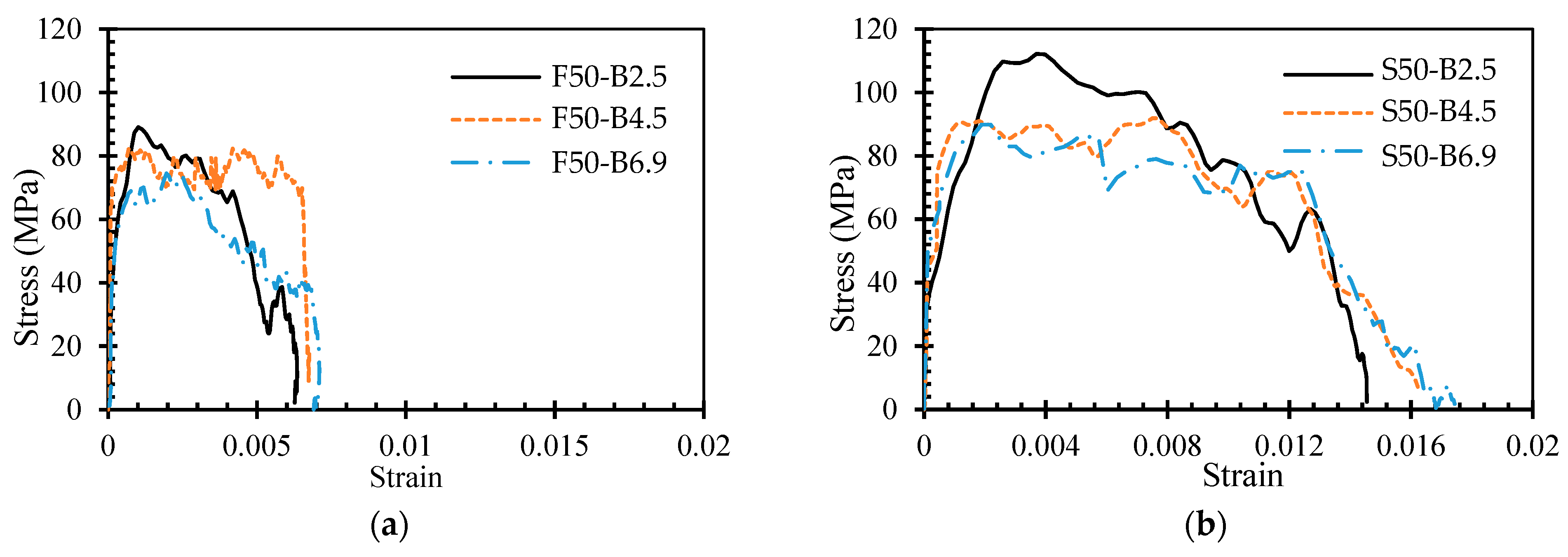
3.2.3. Flexural Strength

Fibers are mostly used to improve the flexural post-crack behavior of mortar and concrete. Depending on the SCM type, the first-peak flexural strength is reduced as the BFP dosage increases [47,50]. This drop in flexural strength was minimal for fly-ash-based and significant for their slag-based corresponding composites, as concluded by Azzam et al. [47]. According to their findings, 50% fly-ash-based and 50% slag-based composites with 6.5% BFP showed up to 13 and 35% reduction, respectively, relative to their counterpart with 2.5% BFP. This is due to the increased intensity of the air void and ITZs produced by the greater BFP dosages. Since micro-crack initiation and spread are easily possible in the ITZs, the first-crack load reduces.
The load–deflection curves of NFRCC with increasing BFP dosages show improved post-cracking performance as a result of the pellets’ pullout mechanism, presented in Figure 4, as claimed by Azzam et al. [47]. The combinations with the higher BFP doses (4.5 and 6.9%) demonstrate a deflection–hardening tendency similar to cementitious composites with ductile fibers like steel. The Ri index of the specimens with 2.5% BFP was higher than 0.6, while it was higher than 1 for the specimens with 4.6 and 6.9% BFP doses [47,50]. These patterns support the effective post-cracking functionality of the NFRCC with BFP.
With the inclusion of BFP, the produced composite’s toughness was dramatically improved. Azzam et al. [47] observed that F50-B4.5 and F50-B6.9 samples showed 36 and 45% greater toughness than F50-B2.5 (27.4 J). Accordingly, S50-B4.5 and S50-B6.9 had 33 and 45% higher toughness than S50-B2.5 (30.3 J). The abundance of BFP, which stopped the propagation of microcracks and bridged them, improved the toughness beyond the first crack. At a fixed BFP dosage, the toughness of the slag-based mixtures was relatively higher than that of their fly-ash-based counterparts, as found by Azzam et al. [47]. The toughness of mixtures S50-B2.5, S50-B4.5, and S50-B6.9 were 10, 7, and 10% higher than that of the corresponding fly ash mixtures. Relative to fly ash, slag has a more rapid reactivity because the distribution of BFPs in the slag-based mixtures was found to be more homogeneous than it was in the fly-ash-based samples, which exhibited congregating near the bottom, as shown in Figure 5.
According to Elhadary and Bassuoni [50], the high tensile capacity of BFPs is combined with a superior tensile strength and a reasonable modulus of elasticity, which arrested the propagation of macro-cracks effectively in the composites and supported the load upon reaching a second peak load. The polyamide resin’s role in shielding the BFPs from the adjacent alkaline matrix also prevented any surface degradation on the pellets.

3.2.4. Impact Load

The durability of cement-based materials under tensile and impact stresses is constrained by their brittle behavior. Hence, the behavior of NFRCC subjected to sudden impact load needs to be evaluated. The split Hopkinson pressure bar (SHPB) test is one way to investigate this property. The average dynamic compressive strength of NFRCC dramatically dropped as the BFP dosage rose according to the impact stress–strain curves (Figure 6) of NFRCC, as reported by Azzam et al. [54]. As the dosage of the BFP increased, more ITZs were formed within the matrix, where micro-cracks started to grow. Additionally, the greater the BFP dosage, the more air void was noticed, which decreased the ultimate strength of the hardened composites, according to a study by Azzam et al. [47]. This phenomenon led to a drop in the ultimate dynamic compressive strength. However, Azzam et al. [54] observed that higher BFP dosages increased ductility because of the bridging effect of BFP. Compared to F50-B2.5 (0.622%), the strain at failure for F50-B4.5 and F50-B6.9 was raised by 8 and 15%, respectively. Slag-based NFRCC samples had up to 26% higher strain at failure and up to 176% higher energy absorption capacity compared to the fly-ash-based samples. This was implied by the more effective bond between the BFP and slag-based cement matrix. More fractures are created when the composite deforms by generating more internal energy to balance out the external energy acting on the composite. As a result, raising the dosage of BFPs caused more fractures to form, increasing the level of energy absorption. The post-cracking behavior was also improved by the higher BFP dosage. Adequate dosage of fiber gave the BFPs a greater chance to be distributed in the failure area, which effectively stopped cracks from spreading and eventually increased the toughness.
Figure 7 illustrates the failure mode of the specimens under impact load experimented by Azzam et al. [54]. The mortar was broken up into a pattern of strewn pieces of varying sizes. The authors observed that the BFPs failed by pull-out, and the fractured fragments were larger compared with those of steel-reinforced composites. The BFPs percentage had no visible effect on the scattered pieces. The BFPs were able to bridge the developed cracks and stop their growth in the matrix, which produced a high reluctance to pull out and was the primary mechanism responsible for increasing the capacity of NFRCC to absorb energy. The fibers or pellets will pull out of the mortar if the load is high enough, causing interfacial damage [55].

3.2.5. Single-Pellet Pullout Test

The interfacial bond of BFPs with concrete matrix to loading schemes can be evaluated by the single-pellet pullout test. The bond strength of a single pellet can be calculated as the ratio of the maximum force on the force–slip graph over the embedded shear surface of BFP using the SHPB test Azzam et al. [54]. The interfacial bond of BFPs with the concrete matrix significantly increases as the pullout displacement rate increases. For instance, in the study conducted by Azzam et al. [54], the bond strength of BFPs with the slag-based NFRCC matrix at 50 mm/min displacement rate was 43% greater than that at the lower rate of 0.2 mm/min. The authors also found that a low displacement rate and slower pellet displacing from the matrix led to a smoother interface with fewer hydration products and no signs of pellet damage (Figure 8a). As evidenced by the tested pellets’ smoother surface, lower bonding strength, and debonding energy, the effect of the low strain rate applied to the specimens gave the load sufficient time to substantially affect the ITZ and weaken the interfacial bond between the concrete matrix and BFP. Conversely, at a 50 mm/min displacement rate, more hydration products were adhered to the pellet with significant surface damage (Figure 8b). The interfacial bond between the pellets and concrete matrix was gradually weakened by the high strain rate over a very short period, leading to an increased pullout resistance of the BFP. Thereby, the applied stain rate affected the BFP pullout behavior of BFPs.

3.3. Phase III (Durability Properties)

3.3.1. Cyclic Freeze–Thaw and Wet–Dry Exposure

The durability of the concrete is a significant factor in concrete construction to transfer stresses effectively to the reinforcing bars. However, extreme exposure scenarios such as freeze–thaw (F/T) and wet–dry (W/D) cycles may adversely affect this mechanism. Thus, the durability of concrete in such an environment is to be assessed. As stated by Bediwy et al. [40], composites with or without slag and Ns had up to 19% lower compressive strength after the combination of the cyclic freeze–thaw (F/T) and wet–dry (W/D) exposure due to the formation of micro-cracks in the matrix. The compressive strength of the control mixture S40-B0.0 decreased by 25% after the same exposure, whereas the presence of BFP in S40-B2.5, S40-B4.5, and S40-B6.9 underwent much less reduction in compressive strength of about 10, 4, and 8%, respectively. This was alluded to the higher efficiency of the BFPs at controlling micro-cracking in the cementitious matrix due to better interfacial bonding relative to other fiber types used in the same study (e.g., steel fiber). The BFPs maintain the integrity of the matrix and control micro-cracks over the full combined exposure period. The combining effect of Ns and slag at modifying the pore structure also holds back the reduction in its compressive strength.
All specimens tested by Bediwy et al. [40] demonstrated a decrease in the first-crack flexural strength when compared to the reference values before exposure. For instance, following the cyclic regime, the average residual first-crack strength decreased by 19% on average. The tensile stresses produced during the F/T phase of the exposure initiated micro-cracks that reduced the matrix’s strength. The F/T and W/D cycles, especially for the composites reinforced with large amounts of BFP, had little effect on the post-cracking characteristics of NFRCC. As demonstrated by conserving higher residual flexural strength with increasing the BFP dosage, the presence of BFPs in the matrix helped to postpone the propagation of these cracks during the initial stage.
Consecutive F/T and W/D cycles on NFRCC specimens produced similar toughness trends with less reduction. Compared to the S40-B0.0 composite, S40-B2.5, S40-B4.5, and S40-B6.9, showed 279, 381, and 398% increment in the energy-absorbing capacity (toughness), respectively, after the combined exposure. The SEM image analysis by Bediwy et al. [40] revealed that the better bond between the matrix and the textured grooves in the longitudinal direction of the BFPs was responsible for the improved post-cracking performance of specimens reinforced with BFPs, as these grooves served as a host for the deposition of the hydration products, similar to Figure 8.

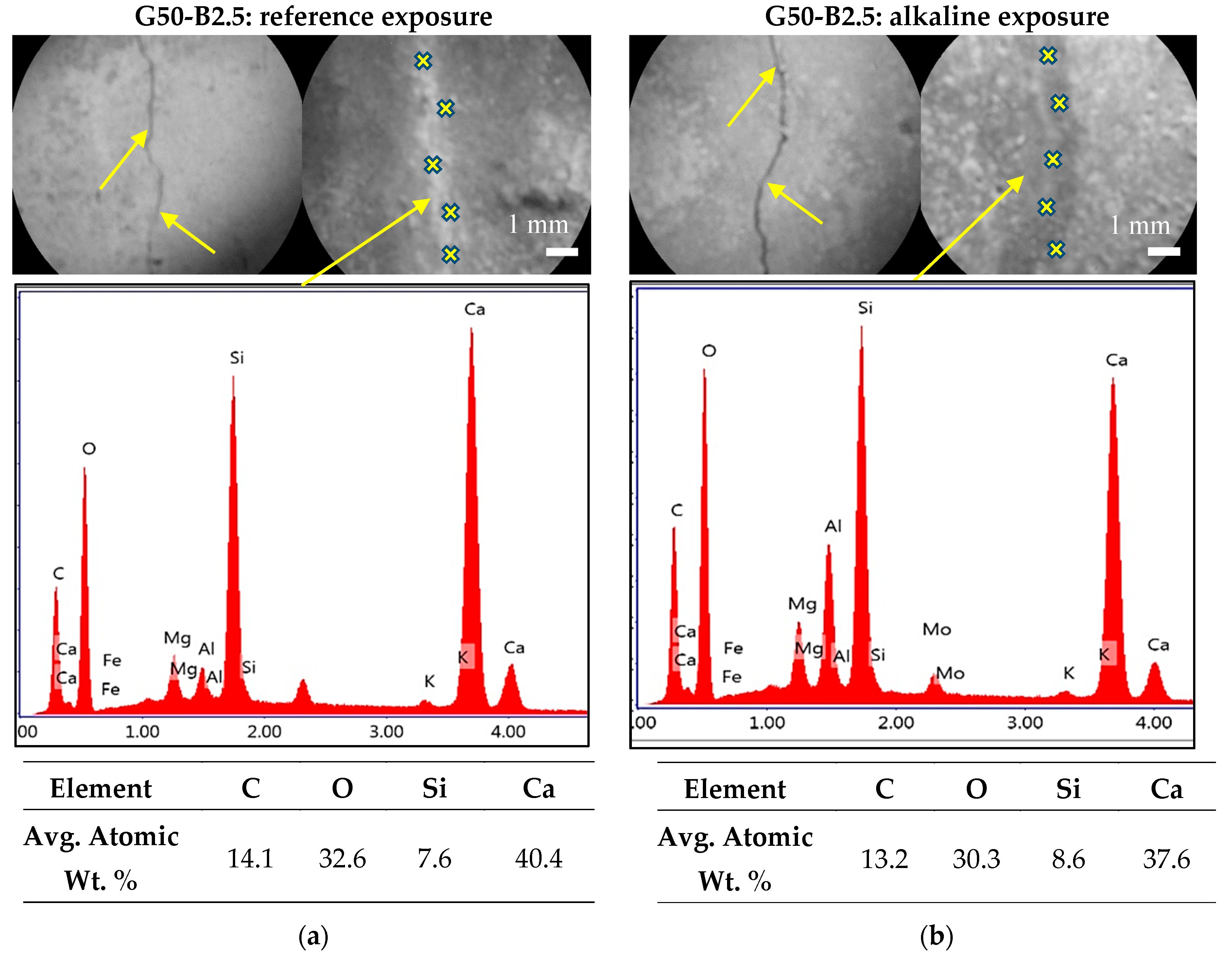
3.3.2. Alkaline Exposure

Highly alkaline media are a harsh exposure that could have an impact on the mechanical and microstructural characteristics of cement-based products using delicate types of fibers. Hence, the acceptability of BFPs in NFRCC requires evaluation. Azzam et al. [56] exposed the uncracked and pre-cracked NFRCC specimens with BFPs to alkaline environment exposure for six months after initial curing. The authors found that all the NFRCC samples remained intact after alkaline exposure. The uncracked samples shrank up to ±0.011% after the exposure period, varying according to the SCM and the dosage of BFPs. The control specimens with BFPs shrank slightly more than their counterparts as the BFPs restricted the volume change. On the other hand, the pre-cracked specimens showed minor extension at the final stage of the period of alkaline exposure, ranging from 0.003 to 0.011%. Extended alkaline exposure allowed the alkaline solution to affect BFPs, which undermined the pullout toughening mechanism. Nonetheless, the matrix benefited from the exposure, as seen by the stiffness and flexural strength of the composite.
After being exposed to alkaline, the flexural post-crack behavior, particularly strain softening and hardening, remained unchanged, which was primarily dependent on the BFPs. This happened because of the long-period pozzolanic reactions of the cementitious materials. Nevertheless, this exposure had a deleterious impact on toughness for a greater BFP dosage, which remarkably decreased by 23 and 24% for F50-B4.5 and S50-B4.5 samples, respectively.
Moreover, self-healing was observed in the pre-cracked samples during the exposure period. Here, the generated cracks were blocked in all composites. Figure 9 depicts the surfaces of pre-cracked slag-based NFRCC specimens before the exposures and entirely filled up with self-healing products after the exposures. This corresponded to the relative enlargement of these samples and a rise in dynamic modulus of elasticity (REd) due to easier liquid entry via the cracking surfaces. As a result, the binder reactivity led to C-S-H gel and calcite formation. Because of the formation of the initial C-S-H from the cement hydration process, the average calcium-to-silicate ratio (Ca/Si) for slag-based NFRCC was found to be 1.14 under the reference exposure and 1.19 under the alkaline exposure in the ITZ with BFPs, conforming to Figure 10. It is also visible that the eminence of the ITZ links between pellets and matrix was also enhanced by the refining of the matrices’ pore structure. This corresponds to the advantageous effects on the matrix standard in the case of both the exposures that conformed to the sample intactness flexural capacity and stiffness maintenance and surface crack healing. Table 4 presents the thermal analysis results after six months under different exposures.
A considerable decrease in ductility was seen following the alkaline exposure. This decrease was related to BFP, which was indicated by the equivalent increase in matrix standard and refining pore structure and ITZ following both types of exposures. The microstructural study by environmental scanning electron microscopic (ESEM) image in Figure 11 revealed that the BFP degraded significantly after alkaline exposure. The polyamide resin exhibited substantial micro-cracking and ripping and the breaking of basalt strands after the flexural load test. As a result, the bridging capacity of BFP had been compromised, and, thus, the effectiveness of the pull-out had been hampered by the fiber breakage.

3.3.3. Salt–Frost Exposure

Combined chemical and environmental loading through salt–frost exposure negatively affected the NFRCC. The durability of BFP-reinforced NFRCC specimens under salt–frost scaling was examined by Azzam et al. [56]. The authors exposed the uncracked and pre-cracked NFRCC specimens with BFP to salt–frost exposure (508 thermal cycles) for six months after 56 days of initial curing. The authors found that some of the NFRCC samples showed performance threats after salt–frost exposure. All the uncracked specimens withstood this exposure because of the SCMs. The initial curing time of 56 days reduced the solution penetrability and helped the uncracked specimens to withstand this exposure. Nevertheless, cyclic freezing–thawing in the solution of salt demonstrated excessive expansion for several pre-cracked composites, which practically led to the diminution of flexural strength, toughness, and stiffness, indicating practical threats.
Even though none of the pre-cracked samples experimented on by Azzam et al. [56] did not fail under the alkaline exposure, the detrimental impact of salt–frost exposure was more significant in pre-cracked samples than in uncracked samples because of the salt solution’s direct access inside the cracking surface. The uncracked samples expanded up to 0.013% following this exposure, unlike alkaline exposure, where the samples shrank on an average of 0.006%. The pre-cracked samples expanded more than their counterparts, up to 0.046%. This happened because of the decrease in the REd and macro-cracks on the surface, leading to the collapse of the sample.
This exposure also had an adverse effect on the flexural first-crack strength. For instance, F50-B2.5 demonstrated a 37% drop, and S50-B2.5 demonstrated a 31% drop in the first-crack strength compared to their corresponding samples under the reference exposure, respectively. The increase in BFP dosage, just like the reference and alkaline exposures, significantly reduced the first-cracking flexural strength depending on the SCM type. The first-cracking flexural strength was found to be 16% for F50-B4.5 and 9% for S50-B4.5, which was less than that of their corresponding mixtures after this salt–frost exposure containing 2.5% BFP. Strain softening was observed in the composites with 2.5% BFP, and strain hardening was observed in the composites with 4.5% BFP. Again, due to composite deterioration, the capability of the composites to regain their load-carrying characteristics following the first cracking was hampered by considering the toughness also reduced by up to 37%.
After the salt–frost exposure, the CH contents were drastically reduced in comparison to their base values at 56 days, as presented in Table 4. Nevertheless, the attributes of the pore structure of the composites became coarser, which was not seen in the case of the reference and alkaline exposures. Here, compared to their baseline states, the porosity of F50-B2.5 and S50-B2.5 are raised by 14% and 9%, respectively. Meanwhile, the percentage of the micro-pores fell by 15, 17, and 21%, respectively. These findings by Azzam et al. [56] revealed that the salt solution and the concurrent activities of low or freezing temperatures prevented the development of microstructure to various degrees. The apparent coarser microstructure following this salt–frost exposure, integrity reduction with the pellets at the ITZ, and, therefore, the decrease in the toughness and flexural strength was caused by the internal micro-cracking of the matrix, as indicated in Figure 12. Thus, it reduces the bond between the BFPs and matrix, and as a result, flexural testing enables fiber pull-out. No indication of the deterioration in BFPs was noticed on the surface of the pellets following flexural loading (Figure 13). Therefore, raising the dosage of BFPs to 4.5% improved the composite lifespan by preventing swelling and cracking.

3.4. Phase IV (Repair and Structural Applications)

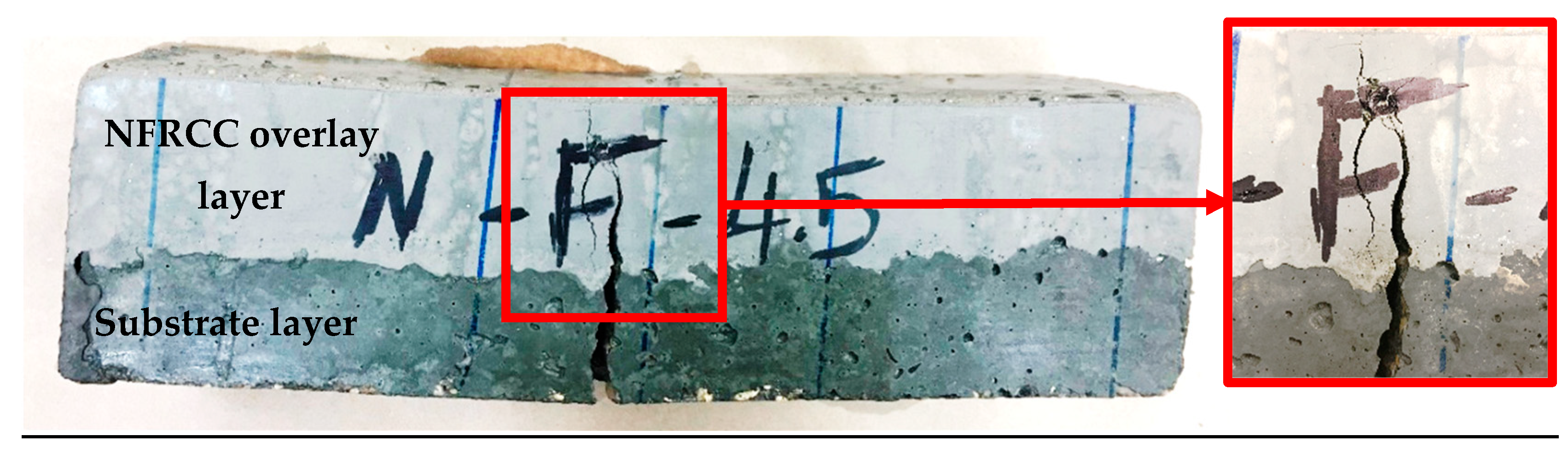
3.4.1. Bond Behavior

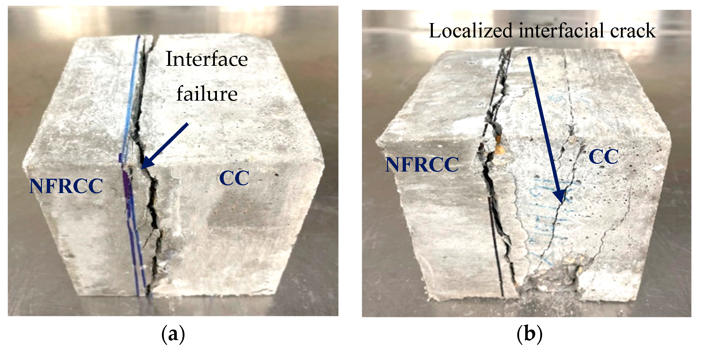
Bond between NFRCC Concrete and Regular Concrete

To improve the quality of concrete surfaces (e.g., concrete pavements, bridge decks), a bonded overlay casting over the existing substrate helps to elevate the structural capacity. An overlay assembly consisting of a 50 mm overlay of BFP-reinforced NFRCC and a 50 mm regular concrete substrate was adopted by Azzam et al. [57] (Figure 14) to determine their flexural performance following the ASTM C1609 [58]. All specimens displayed comparable first-crack strength to the reference concrete due to the location of the substrate layer on the tension side. The post-crack behavior was enhanced because of the presence of BFP in the overlay. Azzam et al. [57] observed that the toughness of F50-B4.5 and S50-B4.5 overlay assemblies was 324 and 471% higher than the conventional concrete at the 2-mm test deflection limit, respectively. Cracks from the substrate layer propagated to the overlay and then were controlled because of the presence of BFPs. The authors concluded that this phenomenon indicated a strong bond within the layers. The cracks at the interface did not propagate sideways because of the system’s monolithic behavior, as can be seen in Figure 14. A similar finding was also observed by Bediwy et al. [40] for 40% slag-based NFRCC layered beams. The load–deflection curves of F50-B4.5 and S50-B4.5 overlay assemblies with substrate concrete found by Azzam et al. [57] are shown in Figure 15. There is a sharp drop in load capacity once cracks do eventually reach the overlay. The BFPs, however, were allowed to withstand the induced stresses through the excellent bond with the matrix. Toughness was also observed to be increased by Bediwy et al. [40] by 162, 262, and 246% for S40-B2.5, S40-B4.5, and S40-B6.9 layered prisms, respectively, in comparison to the S40-B0.0 beam (13 J). The restraining role of BFPs helped the NFRCC to achieve adequate thermal compatibility as well as dimensional stability with the substrate concrete. The long service life of the repair/overlay assembly was ensured by the efficient integrity of NFRCC with the substrate concrete without any bonding agent, where the failure mode typically occurred in the substrate.
The residual bond strength between the NFRCC and regular concrete was examined by Bediwy et al. [40] using a direct tension test (pull-off). The results are presented in Figure 16. The average pull-off strength results show that the bond strength of the samples S40-B2.5, S40-B4.5, and S40-B6.9 increased respectively by 73, 70, and 68% compared to the control composite S40-B0.0. The BFPs greatly increased the volume stability of the composites of the layered system. This is why the failure mostly took place in the base layer within 30 to 50 mm below the contact surface, exhibiting strong compatibility between the two layers.
In a layered concrete system, differential shrinkage can affect the bond between the NFRCC and the regular concrete layer, which potentially results in dissociation and premature failure. Hence, a relative shrinkage test can affirm its viability of employing as a concrete layer. Bediwy et al. [40] performed such a test for up to 148 days, where the samples were kept for 28 days in moist curing and 120 days in hot conditions, as presented in Figure 17. According to the test results, the composites containing BFPs had decreased shrinkage values at various curing ages. For instance, samples S40-B2.5, S40-B4.5, and S40-B6.9 reduced the average shrinkage by 13, 10, and 7% compared to the control composite S40-B0.0, respectively, at 1, 7, and 28 days. A higher percentage of BFPs contributed more to reducing shrinkage, which demonstrated the importance of BFPs in preventing differential shrinkage associated with the substrate concrete. After 120 days of subjecting the composites to drying conditions, the authors observed that the specimens without BFPs displayed some shrinkage cracking on the surface, whereas it was eliminated by using BFPs. The micro-cracks were controlled and bridged by the presence and scattered distribution of BFPs, which minimized the shrinkage as a result.

Bond between NFRCC Concrete and Reinforcing Bars

Regardless of their outstanding engineering properties, glass-fiber-reinforced polymer (GFRP) reinforcing bars have distinct bond behavior with concrete. Bediwy and El-Salakawy [59] conducted pull-out tests to investigate the bond behavior of sand-coated GFRP bars with NFRCC, considering different parameters, such as the bar diameter and the dosage of the BFPs. The authors found that the BFP percentage was the key factor in the post-peak load–slip response of GFRP bars embedded in concrete blocks. After reaching the bond strength, size No. 20 GFRP bar (19.5-mm diameter) in the NFRCC with 2.5% BFP showed a sudden drop in load. However, at a dosage of 4.5%, it demonstrated a progressive deterioration with increasing slip values as internal cracks spread, with fibers being essential in bridging these cracks.
The pullout failure load of the GFRP bar and the mode of failure of the concrete block both significantly improved in the presence of discrete BFPs. Bediwy and El-Salakawy [59] observed that using 2.5% BFPs increased the average failure load by 53% when compared with the counterpart control specimen without BFPs. This was because of the role of fibers in controlling the development of crack propagation and better dissipation of bond energy. Increasing the dosage of BFPs caused a good distribution of BFPs over the cross-section of the specimen, as portrayed in Figure 18, which helped in controlling cracks efficiently. As a result, using 4.5% of BFPs within the cementitious matrix increased the failure load by up to 39% with respect to the counterpart specimen with 2.5% BFPs.

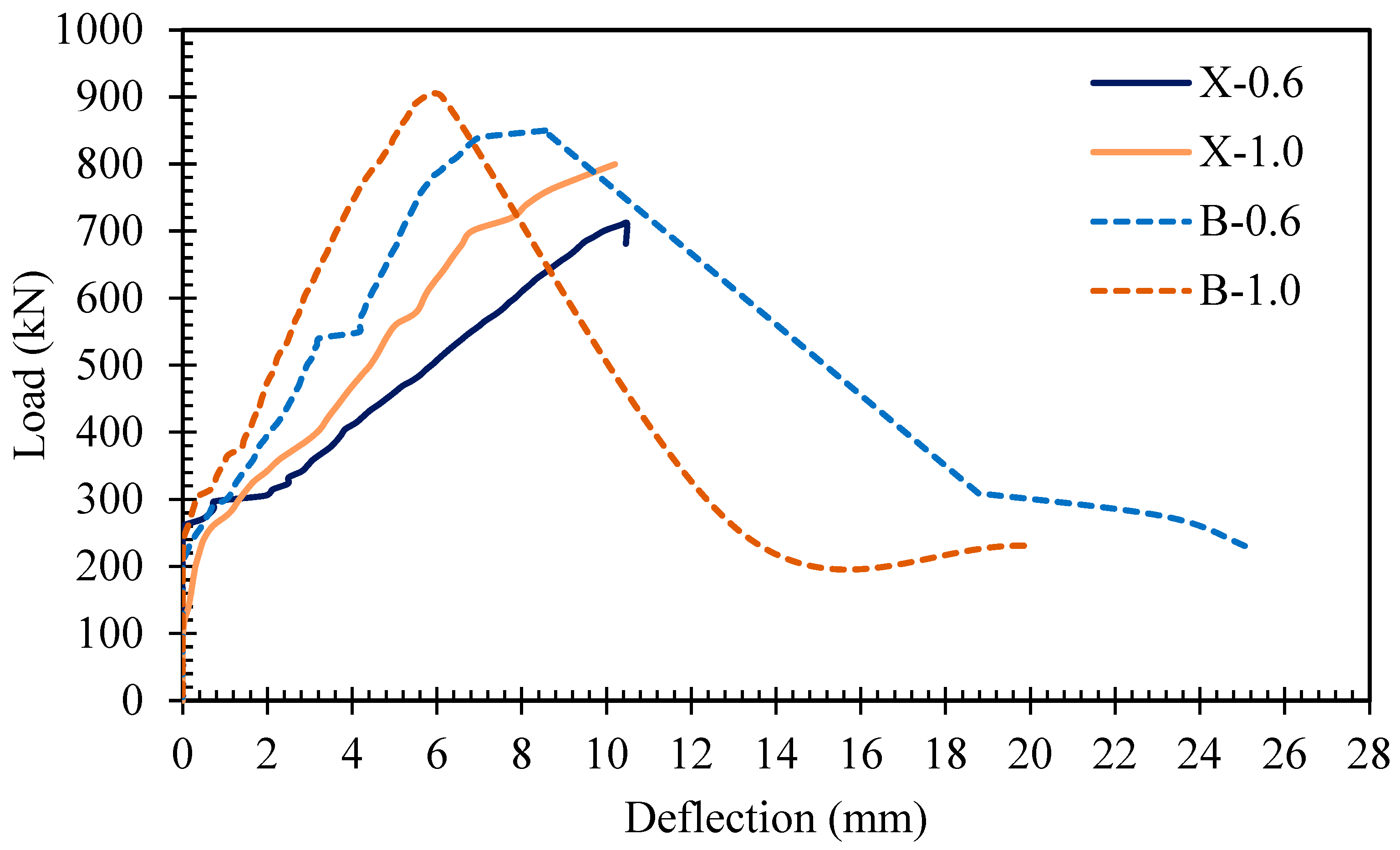
3.4.2. Full-Scale Structural Elements

Since the post-cracking behavior of concrete significantly improves in the presence of BFPs, they are likely to improve the flexural toughness by increasing the capacity of NFRCC deep beams when used in the tension tie zone. Bediwy et al. [61] constructed and tested large-scale simply supported deep beams measuring 2100 mm long with 250 × 590 mm cross-section. The tie zone at the bottom of the beam had a 150 mm thick NFRCC layer with various dosages of BFPs (2.5, 4.5, and 6.9%) and was reinforced with sand-coated, headed-end GFRP reinforcing bars. The test variables were the GFRP reinforcement ratio and the presence of the NFRCC layer. The experimental results for the beams at various loading levels are summarised in Table 5. The authors observed that the incorporation of the NFRCC layer with 2.5% BFPs delayed the initiation of the first crack. The first crack load was enhanced by 20 and 43% for tie reinforcement ratios of 0.6 and 1.0%, respectively. The reinforcement ratio had very little influence on the first crack and diagonal crack loads. The ultimate load-carrying capacity was significantly increased by the insertion of fibers in the tie zone, which improved by 19 and 13% for 0.6 and 1.0% reinforcement ratios. In addition, the energy absorption capacity was improved by up to 84%. The BFPs in the tie zone acted as micro reinforcement, which enhanced the strength of the test beams.
Long beams with an NFRCC layer indicate a deflection softening behavior that is defined by a gradual reduction in the load carrying capacity until failure. The load–deflection relationship constructed by Bediwy et al. [61] at the mid-span of the beams (Figure 19) shows that the control beams exhibited no residual strength after reaching the peak load, whereas beams with NFRCC layer demonstrated a post-peak load behavior with gradually decreasing residual strength because of the bridging mechanism of BFPs.
The addition of fibers resulted in a notably greater ductility index. According to Bediwy and El-Salakawy [62], adopting an NFRCC layer in the tie region with BFP ratios of 2.5, 4.5, and 6.9% significantly increased the ductility indices by 50, 118, and 76%, respectively, with respect to the control counterpart beam. The beam with the highest BFP ratio of 6.9% displayed moderately reduced ductility due to the lower workability caused by fiber congregation when higher fiber dosage is used. Increasing the dosage of fibers also reduced the developed strain in the reinforcement at the same load level, as stated by Bediwy and El-Salakawy [62]. For example, specimens with BFP ratios of 2.5, 4.5, and 6.9% exhibited 20, 34, and 33% drops, respectively, in the developed strains at the ultimate load level compared to the control specimen without BFPs. Furthermore, the incorporation of BFPs in the bottom layer improved the bond within the anchorage zones, where high tensile stresses developed. Along with the GFRP bars in the tie zone, adding the BFPs improved the tensile strength of the fibrous specimens, which led to better distribution of tensile stresses over the stresses over the length of the beams. According to the authors, the aforementioned observations were one of the factors that contributed to enhancing the strength of the diagonal strut and, accordingly, increasing the load-carrying capacity of deep beams.

3.5. Phase V (Hybrid Fibers)

3.5.1. Experimental Investigation

Cementitious matrices with hybrid fiber systems have been the subject of numerous investigations because they perform better than single-fiber systems [63,64]. For example, in binary-scale fiber systems, micro-fibers counteract the coalescence of micro-cracks, while macro-fibers restrain the growth of macro-cracks in the matrix [65,66]. Hence, the behavior of the NFRCC reinforced with a hybrid system of BFPs and other fibers requires evaluation. In an investigation, 1% micro-polyvinyl alcohol fibers (PVAF) were used by Elhadary and Bassuoni [50] in combination with macro-BFP, which enhanced the compressive strength of NFRCC by up to 27% when compared to the equivalent combinations without micro-PVAF. Additionally, the inclusion of micro-PVAF changed the failure mechanism of the composites from sudden matrix crushing to gradual macro-crack formation, where the matrix was left undisturbed after reaching its limit, as evident in Figure 20. This happened because of the hydrophilic nature of PVAF, which lowers the w/b ratio in the paste near the ITZs [67]. Hydroxyl groups (OH-) on the PVAF surface also create hydrogen bonds within the molecules that improve interfacial bonding with the cement matrix [68,69]. The bridging effect of PVAF functions as an evenly distributed reinforcing system, preventing the formation of micro-cracks in the matrix.
The flexural strength test on a hybrid fiber system by Elhadary and Bassuoni [50] showed minimum declination in the bearing load, even though they showed a pseudo-deflection–hardening behavior and continued to bear a large amount of load until obtaining the desired deflection compared to the similar mixtures made up of a single BFP. The synergistic interactions between randomly oriented micro-PVAF and macro-BFP, as shown in Figure 21, enhanced the ductility and toughness by up to 61% when compared to that of mixtures without PVAF, even though the load-bearing capacity reduced slightly.
The flexural strength test by Elhadary and Bassuoni [50] revealed that 1% micro-PVAF with macro-BFP improved the first-crack load by up to 46% by diminishing the negative effects of a higher dosage of BFPs. This can be attributed to the hydrophilic and chemical properties of PVAF, which enhanced the ITZs and interfacial bond. The crack-bridging mechanism of micro-PVAF lowered stress concentration at the edge of micro-cracks, which subsequently improved the first-crack flexural load [67,71].
The adhesive capacity of the NFRCC specimens, when 1% micro-PVAF is combined with BFPs, was also reported to be increased markedly in the study conducted by Elhadary and Bassuoni [72] in a layered specimen of regular concrete and NFRCC. For the S50-B2.5 and S50-B4.5 composite specimens with 1% PVA, the direct shear bond strength and de-bonding energy were found to be rising by up to 37% and 40%, respectively, in comparison to the NFRCC samples with only BFPs. Additionally, 1% PVA caused the fracture plane to diverge from interface failure to localized interfacial cracking and crushing of the CC layer (Figure 22) as a result of PVA’s role in enhancing the adhesive capability at the contact area and friction among two layers.
Incorporating 1% PVAF with BFPs in NFRCC also developed the rebar pull-out resistance in comparison to the composites with only BFPs. Elhadary and Bassuoni [72] reported that the pull-out bonding strength and de-bonding energy of slag-based NFRCC with 1% PVA increased by up to 29% and 27%, respectively, for adding PVAF, depending on the dosage of BFPs. This occurred because of the superior strain-hardening capacity and ductility of these composites. Random distribution of PVAF collaboratively regulated the formation of micro-cracks. BFP macro-fibers afterward inhibited the spread of macro-cracks. This phenomenon can be visualized in Figure 23. In addition to surface adhesion/friction, this enhanced possibility of concrete confinement around the steel rebar increases their resistance against rebar pull-out from the NFRCC.

3.5.2. Modeling

Using the computational non-linear homogenization method, two-scale cubic representative volume elements (RVE) were developed by Elhadary and Bassuoni [73] in ANSYS R19.2 workbench [74] to ascertain the homogenized stiffness coefficients k i j , taking the tensile stress–strain curve and modulus of elasticity of cylinders (75 mm × 250 mm), which were found through experimental tests using a quasi-static direct tension test at 56 days at a displacement rate of 0.2 mm/min. Figure 24 depicts the homogenized RVE assuming anisotropic properties with a mesh size of 100 µm, where each meso-scale RVE consists of the matrix and randomly dispersed micro-fibers oriented randomly in space (x, y, z).
The stress and strain distributions around the BFP for NFRCC with 50% slag and 1% PVAF (S50-P1) are shown in Figure 25, wherein the cumulative displacement increased as a result of the load being transmitted from the BFPs to the adjacent matrix. It is visible that the load peaked shortly before the start of the pull-out process and during the final stage of debonding (red zone).
The FEM adopted by Elhadary and Bassuoni [73] had an excellent correlation with the experimental results, as presented in Table 6, with a maximum error of 10%, demonstrating the validity of the modeling. The models could, therefore, simulate the bond–slip relationships for all mixes throughout the loading. The models were also capable of depicting the development of microcracks and stress–strain distributions around the pellet. Hence, parametric studies were performed to demonstrate the impact of various fiber doses on the homogenized stiffness coefficient ( k i j and the interfacial bond strength of BFP).
Figure 26 show the parametric study result of different volume of PVAF on BFP interfacial bond strength and the homogenized stiffness coefficient, k i j . The authors observed that increasing the dose of PVAF will improve the bond strength and homogenized stiffness coefficient of slag-based NFRCC. PVAF doses of 1%, 1.5%, and 2% increased the projected homogenized stiffness by 2%, 17%, and 26%, respectively, in comparison to NFRCC with no additional PVAF; subsequently, when 2% PVA fibers are added to BFP, bond strength and de-bonding energy increase by 29% and 33%, respectively, as compared to 1% PVA fibers.

4. Concluding Remarks

The comprehensive research program on the fresh, mechanical, durability, and structural properties of the NFRCC prepared with BFP led to the following key conclusions:
  • The amalgamation of nano-silica particles with the high volume of SCM in the developed binders of NFRCC yielded adequate initial flow (180 ± 20 mm) as well as initial (3 to 5 h) and final setting times (4 to 6 h), which makes them practical for casting operations in the field;
  • The early-age and long-term compressive strengths of NFRCC comprising BFPs were significantly high due to the synergistic effects of nano-silica and fly ash or slag, where the nano-modified cementitious composites exceeded 30 MPa and 50 MPa at 1 and 56 days, respectively;
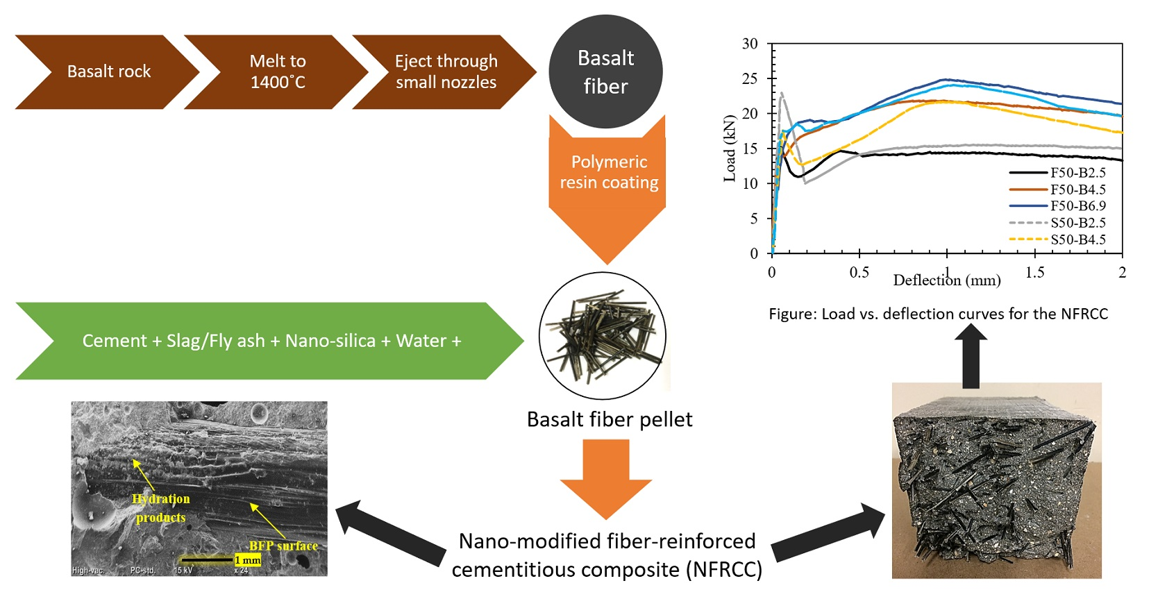
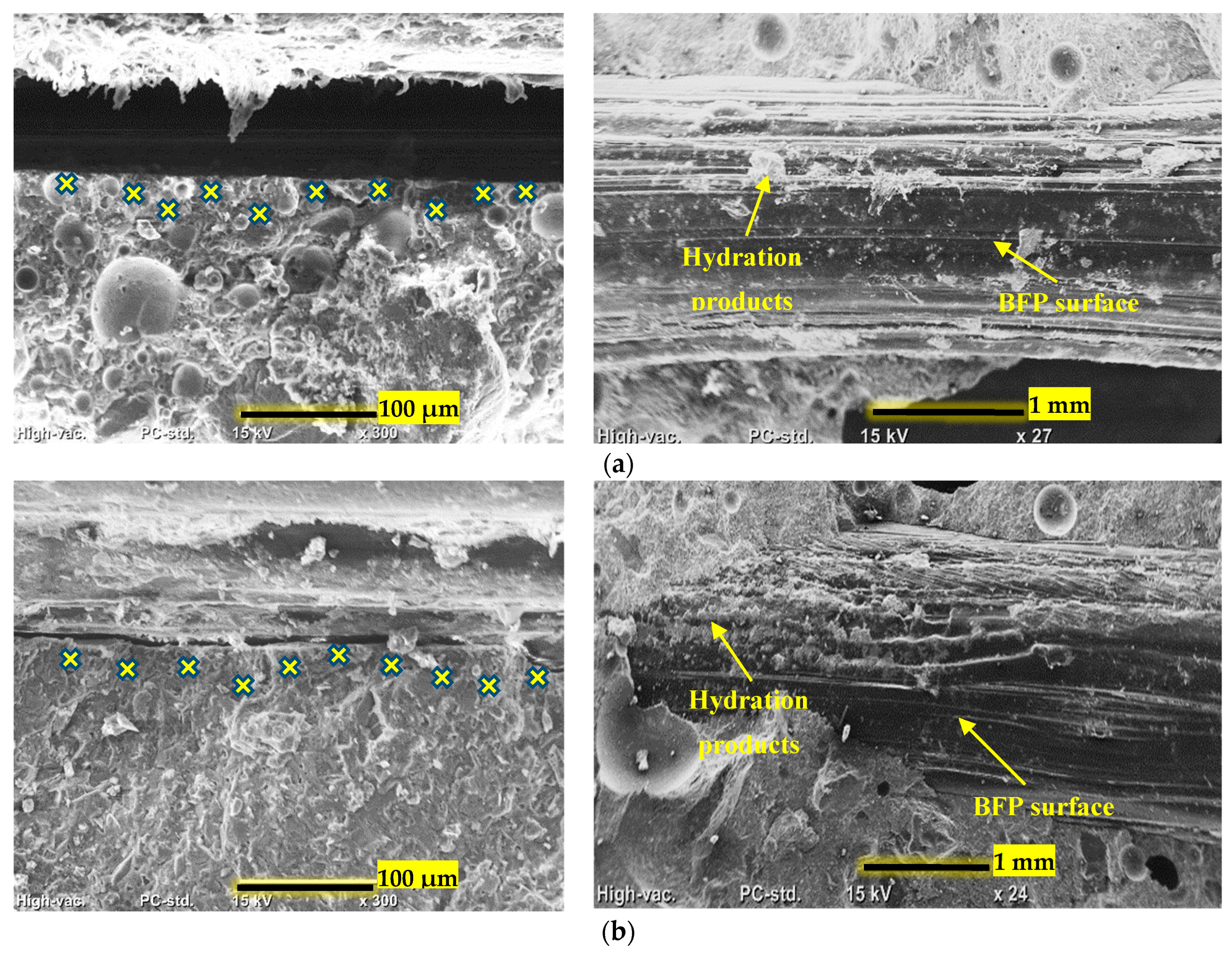
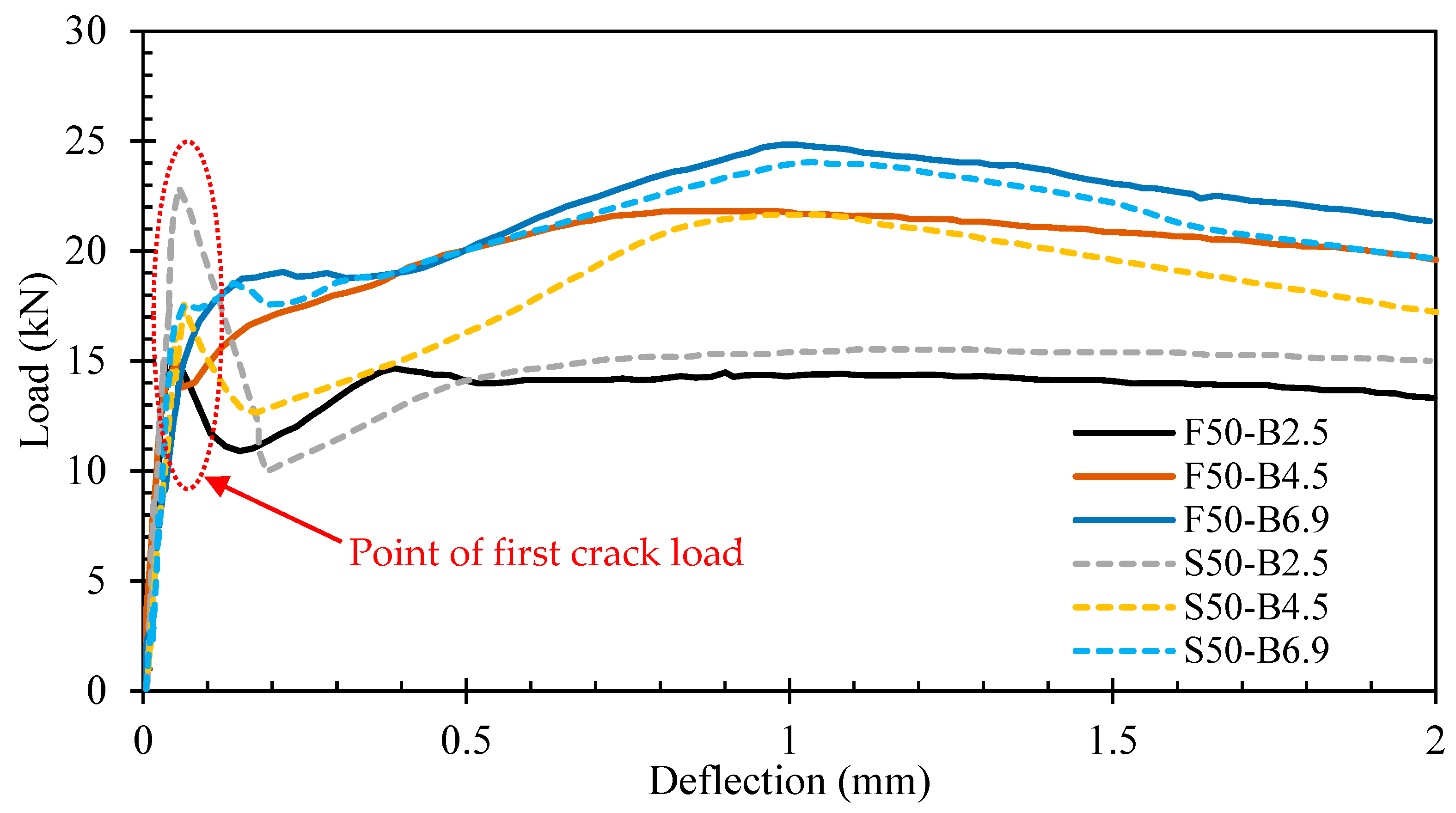
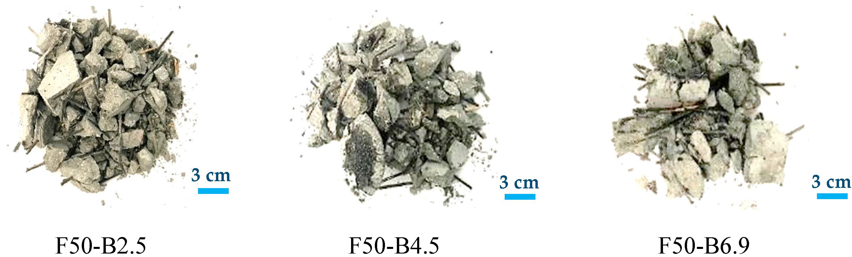
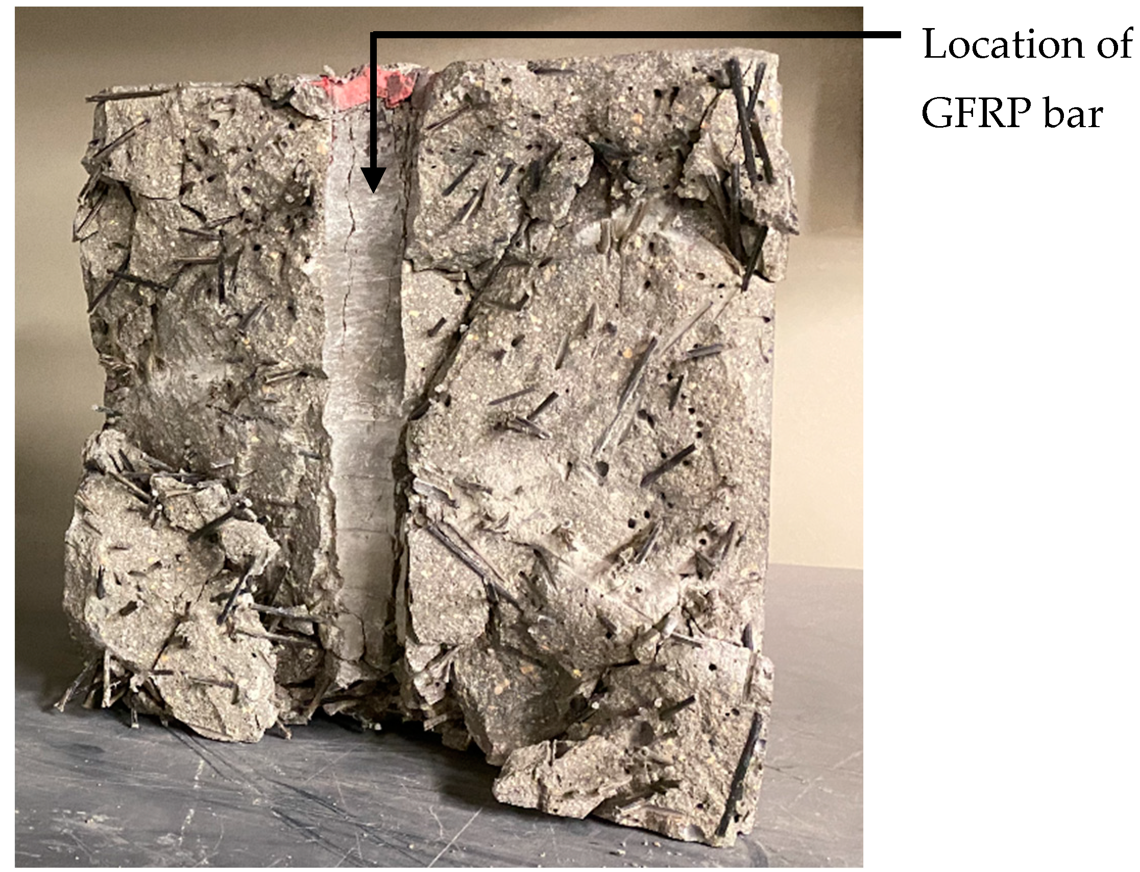
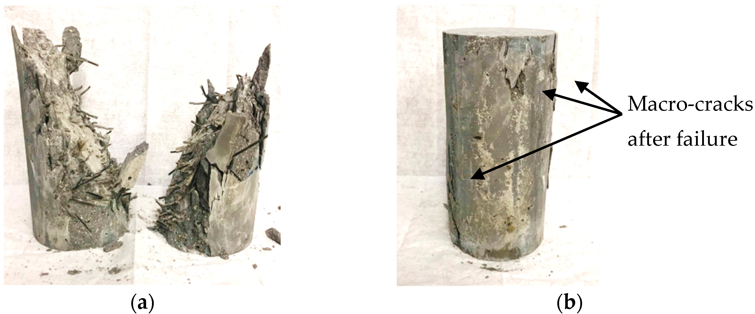
  • BFPs were effective at improving the post-cracking behavior of NFRCC, where, for instance, the increase in BFPs in slag-based mixtures from 2.5% to 4.5% resulted in a 33% increase in toughness. This was alluded to the improved interfacial bond between the BFPs and matrix owing to the precipitation of hydration and pozzolanic products in the BFP-tailored surface grooves that enhanced the interlocking between the pellets and the matrix, which was positively reflected on the pull-out resistance of the pellets as verified through the single-pellet pull-out test;
  • In general, slag-based mixtures exhibited high mechanical properties (compressive strength, tensile strength, impact resistance, etc.) relative to corresponding fly-ash-based ones, owing to the accelerated reactivity of the slag with nano-silica that was projected on the quality of the matrix as well as its interaction with the reinforcing pellets;
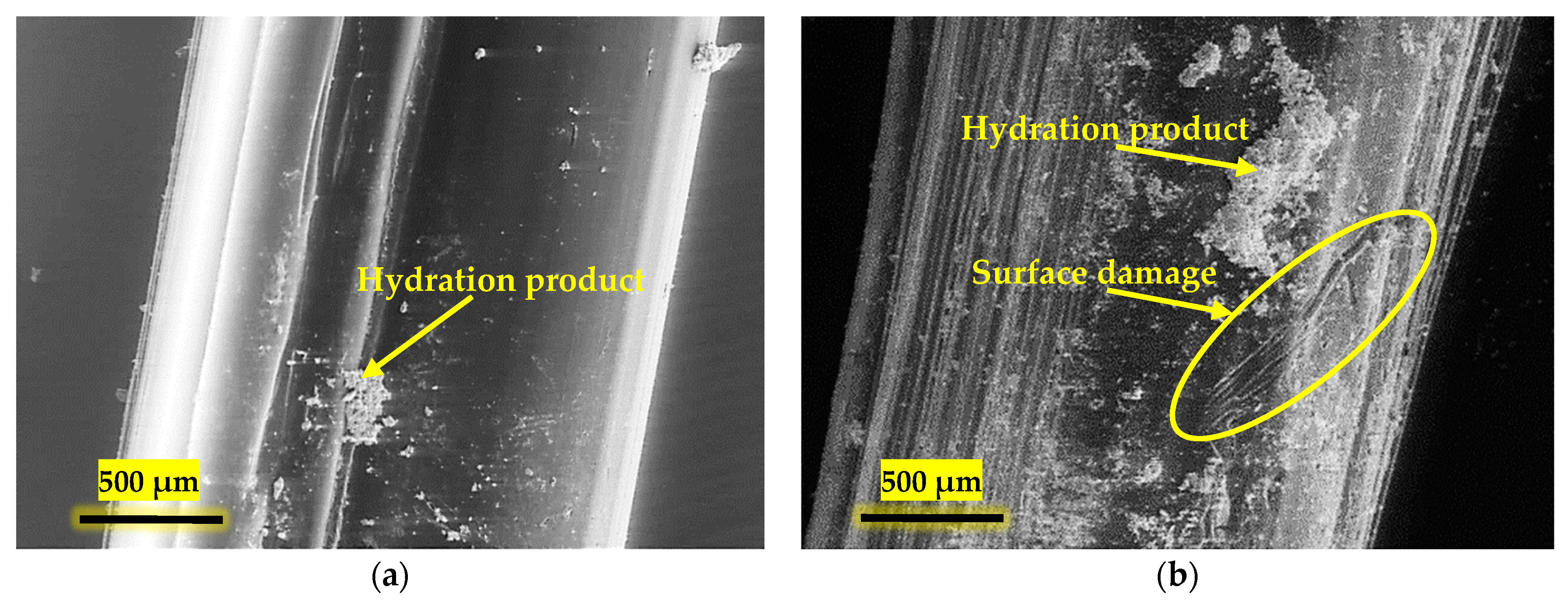
  • Under severe alkaline exposure (1 N NaOH solution at 38 ± 2 °C), all composites experienced ductility losses of 17–25% “un-cracked specimens” and 29–46% “pre-cracked specimens” relative to the reference exposure owing to the degradation of the affected pellets by the exposure (near the surface or directly exposed). Furthermore, the extended exposure of the pellets to the alkaline medium led to a deleterious effect on the polyamide component and, in turn, access of the solution to the basalt component; thus, the pull-out toughening mechanism was compromised by the rupture of basalt strands. However, the exposure was favorable for the matrix, which was reflected in the stiffness and flexural capacity of the composites;
  • Coupled chemical and environmental loading through salt–frost exposure negatively affected the different cementitious composites, where a coarsened microstructure was obtained for all matrices after the exposure (to different levels, though, according to the binder formulation). This was attributed to chemical and physical attacks, which led to the complete failure of most matrices (fly-ash-based and unmodified matrices) along with impairing the interfacial bond between the matrices and the pellets (although the pellets remained intact);
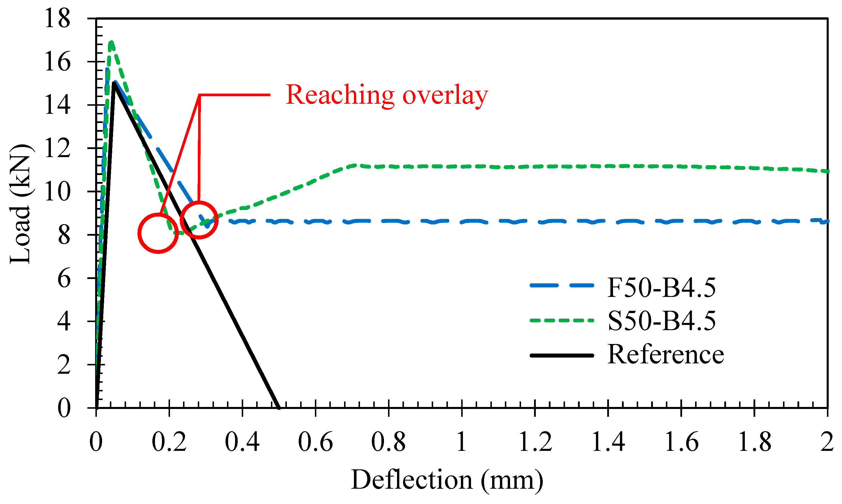
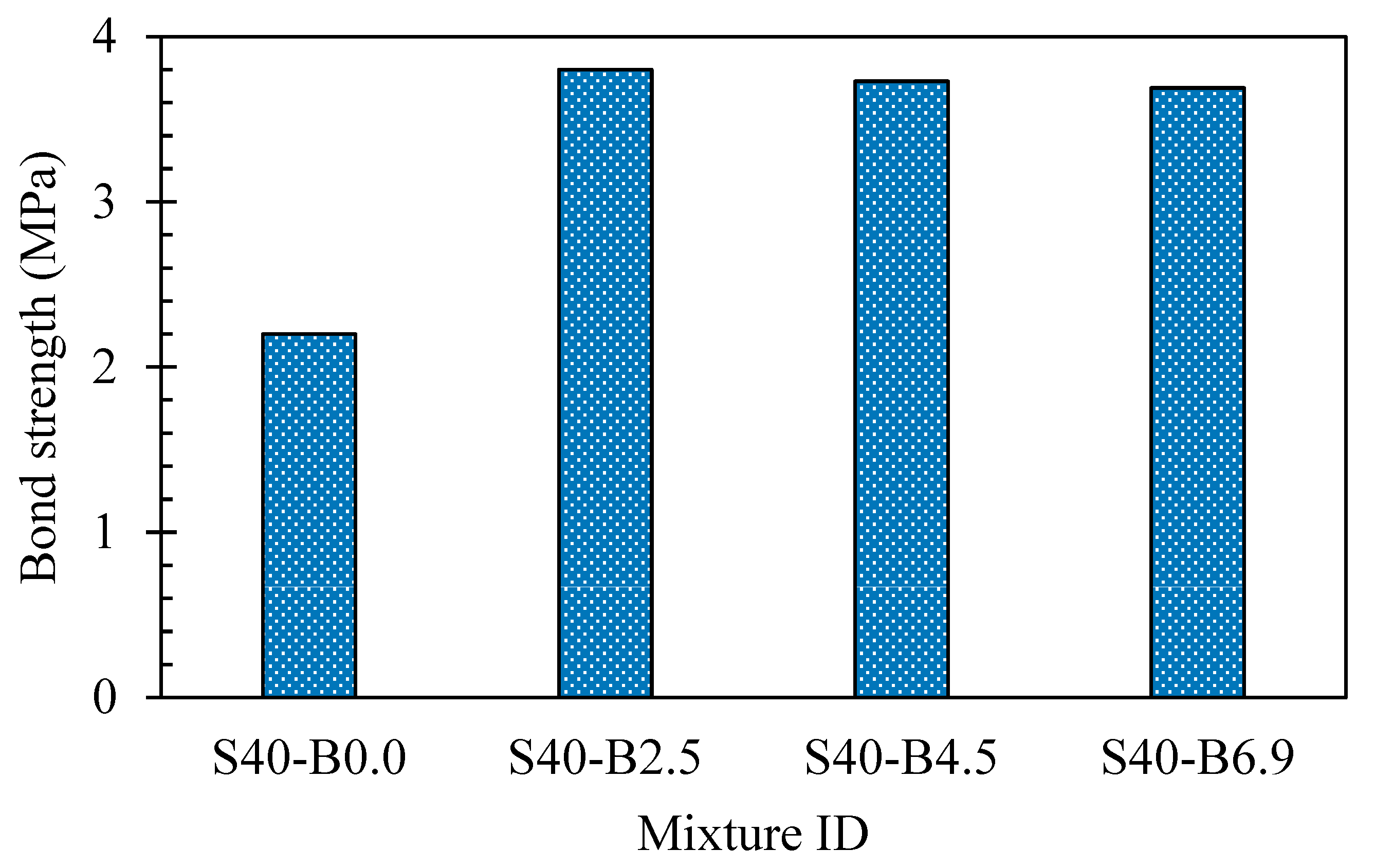
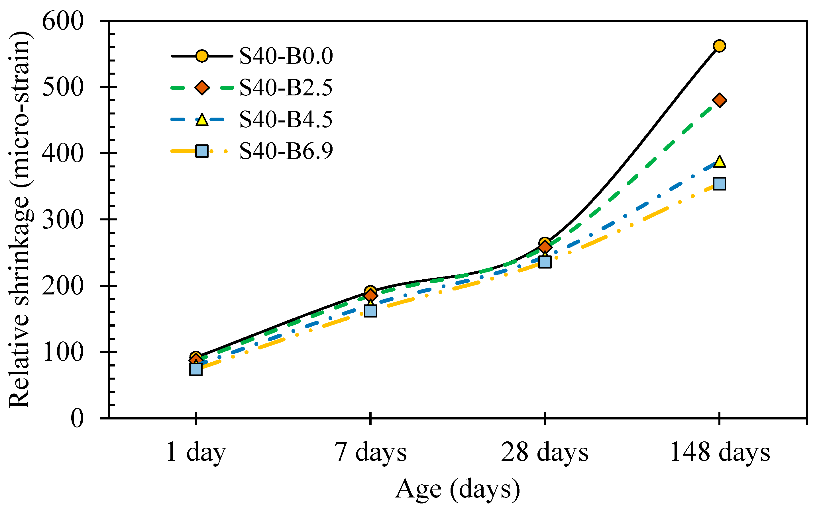
  • The cementitious composites revealed adequate thermal compatibility as well as dimensional stability with the substrate concrete, which is attributed to the restraining role of the pellets. Hence, no surface cracks were spotted during the hot/arid exposure conditions, where the composites’ total restrained shrinkage strains remained low at 416 to 454 με. Accordingly, the cementitious composites had efficient integrity (bond strength) with the substrate concrete, with no bonding agents, where the dominant failure mode was in the substrate, guaranteeing the long service life of the repair/overlay assembly under field conditions;
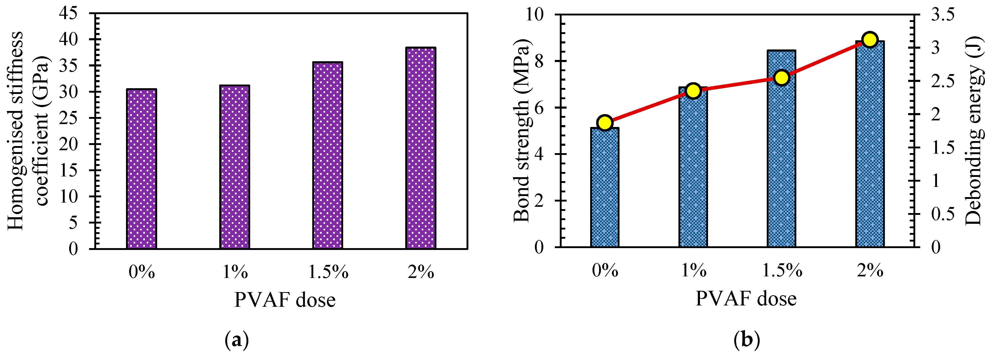
  • The addition of 1% micro-PVA to macro-BFP (hybrid system) resulted in optimal performance of NFRCC in terms of modified pore structure, mechanical capacity, and ductility. While macro-BFP controlled the development of macro-cracks, micro-PVA prevented the nucleation of micro-cracks, accordingly, increasing the performance of the composites;
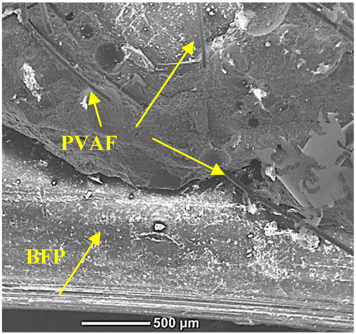
  • The coexistence of 1% PVA micro-fibers with BFP macro-fibers (hybrid system) led to improvement in the bond strength with conventional concrete and ribs of steel rebar due to improving the adhesive capacity and friction at the interfacial zone with CC and efficient interlocking with BFP around steel reinforcement;
  • Large-scale beams with an NFRCC layer demonstrated a deflection–softening behavior that was characterized by a gradual loss of load-carrying capability up to failure. Additionally, the brittle and rapid failure of deep beams with an NFRCC layer in the tie zone was replaced by a more ductile failure;
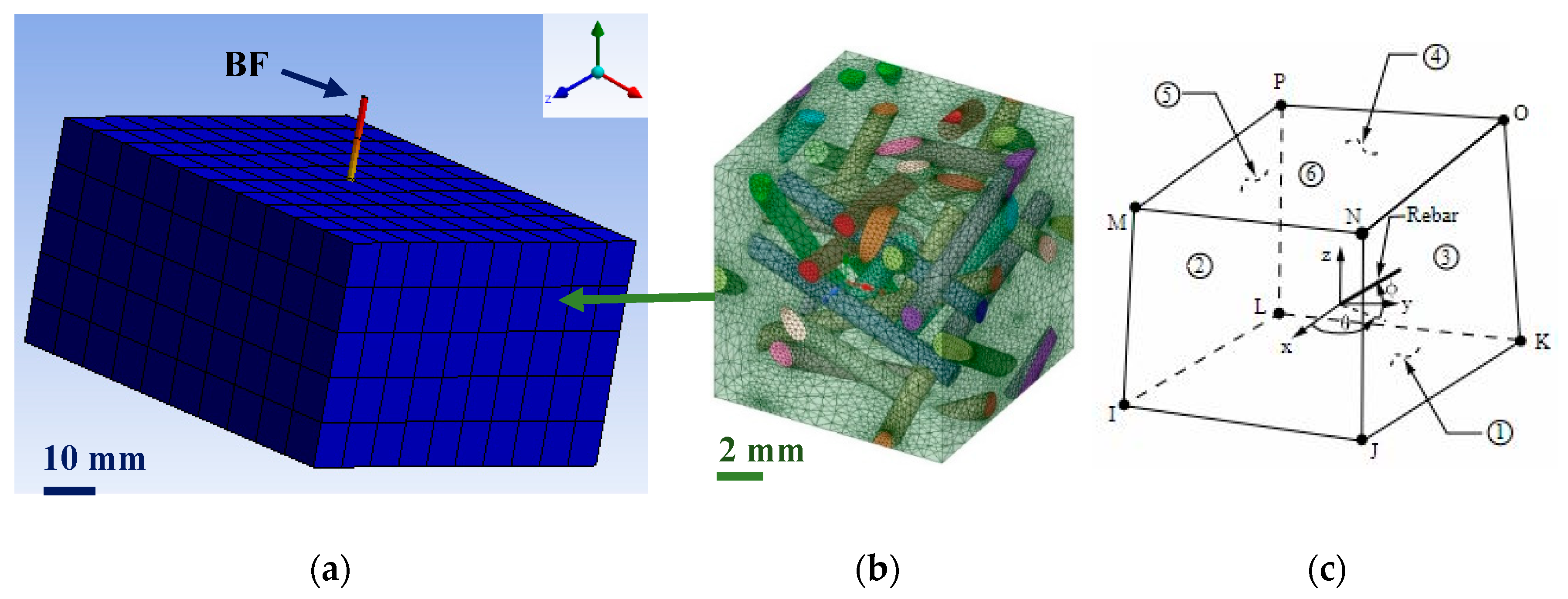
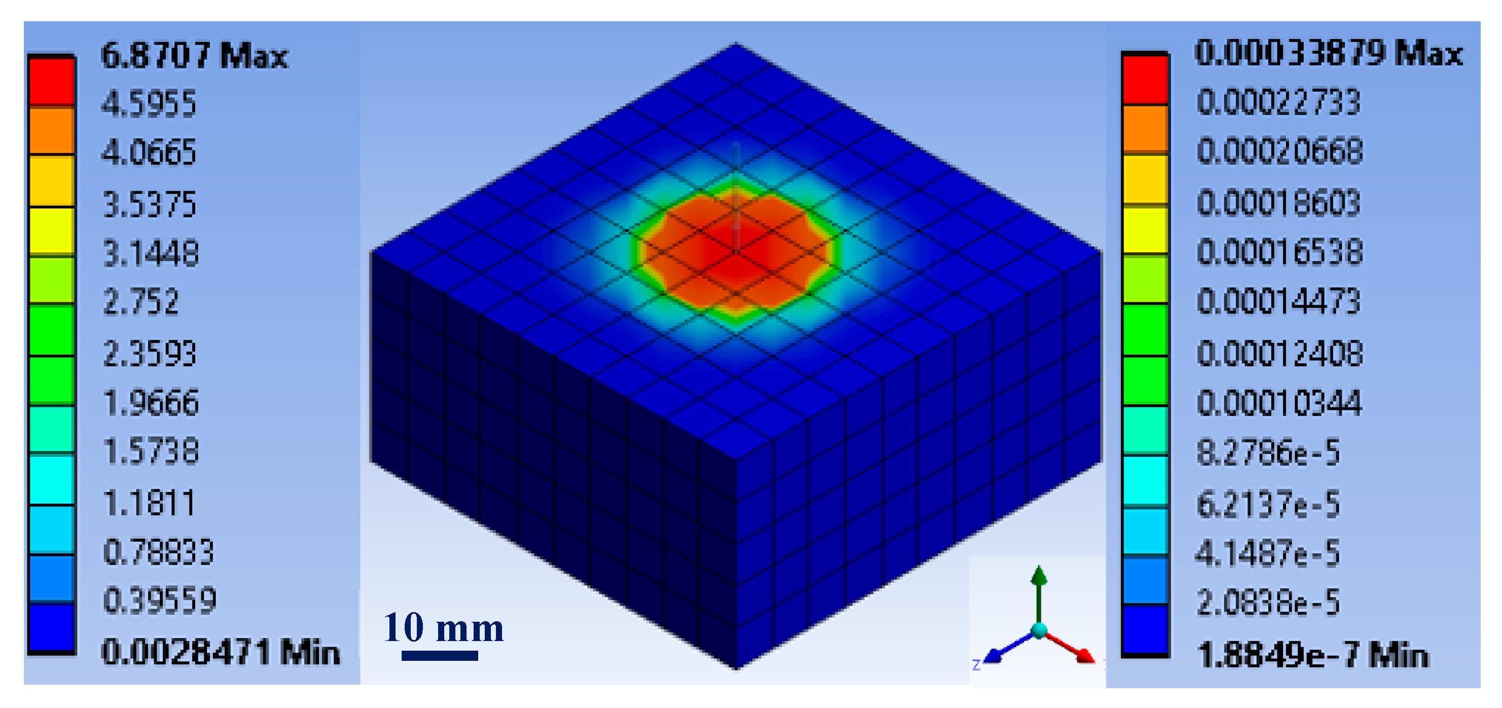
  • The developed mesoscale RVEs homogenization models were capable of predicting the elastic properties of NFRCC. In addition, the FEM revealed that the hybrid PVA/BFP system improved the shear resistance force of box girders shear key system, meeting the AASHTO LRFD interface coefficient of friction and adhesion parameters for rough surfaces;
  • The overall findings from this program indicate that the nano-modified composites comprising BFPs have superior performance, making them potentially an attractive alternative for a variety of infrastructure applications, including repair and strengthening. However, full-scale field studies are recommended for future research to compare the cost-performance attributes relative to other high-performance materials available in the building materials sector. Some of the fundamental properties are still not explored such as durability under different elevated temperatures, mechanical and environmental fatigue behavior, and their ability to resist cyclic load. These properties should be investigated in future to make BFP-reinforced nano-modified composites more acceptable for practical applications.

Author Contributions

T.A.: methodology, data curation, formal analysis, and writing—original draft. A.B.: conceptualization, supervision, writing—review and editing, funding acquisition, and project administration. A.A.: writing—review and editing, and methodology. R.E.: writing—review and editing, and methodology. E.E.-S.: supervision, funding acquisition, writing—review and editing, and methodology. M.T.B.: supervision, project administration, funding acquisition, writing—review and editing, and methodology. All authors have read and agreed to the published version of the manuscript.

Funding

E. El-Salakawy and M.T. Bassuoni highly appreciates the financial support from the Natural Sciences and Engineering Research Council of Canada (NSERC) through their individual NSERC Discovery Grant Programs, which made this exploratory program possible. A. Bediwy appreciates the financial support through the Study in Canada Scholarship. Also, M. T. Bassuoni appreciates the financial support through the University of Manitoba (URGP), which enabled the manufacture of PFB.

Data Availability Statement

All data are original as a reference to the author’s original contributions. They can be provided by the corresponding author upon reasonable request.

Acknowledgments

The authors highly acknowledge the kind support by Sudaglass Fiber Technology, Inc., which is much appreciated. The IKO Construction Materials Testing Facility and McQuade Structures Laboratory at the University of Manitoba, in which these experiments were conducted, have been instrumental to this program.

Conflicts of Interest

Riham Elhadary was employed by the company Tetra Tech. The author declares that the research was conducted in the absence of any commercial or financial relationships that could be construed as a potential conflict of interest.

References

  1. Yang, I.H.; Joh, C.; Kim, B.-S. Structural behavior of ultra high performance concrete beams subjected to bending. Eng. Struct. 2010, 32, 3478–3487. [Google Scholar] [CrossRef]
  2. Bandelt, M.; Billington, S. Impact of Reinforcement Ratio and Loading Type on the Deformation Capacity of High-Performance Fiber-Reinforced Cementitious Composites Reinforced with Mild Steel. J. Struct. Eng. 2016, 142, 04016084. [Google Scholar] [CrossRef]
  3. Meng, D.; Huang, T.; Zhang, Y.X.; Lee, C.K. Mechanical behaviour of a polyvinyl alcohol fibre reinforced engineered cementitious composite (PVA-ECC) using local ingredients. Constr. Build. Mater. 2017, 141, 259–270. [Google Scholar] [CrossRef]
  4. Islam, M.J.; Islam, K.; Shahjalal, M.; Khatun, E.; Islam, S.; Razzaque, A.B. Influence of different types of fibers on the mechanical properties of recycled waste aggregate concrete. Constr. Build. Mater. 2022, 337, 127577. [Google Scholar] [CrossRef]
  5. Bentur, A.; Mindess, S. Fibre Reinforced Cementitious Composites; CRC Press: Boca Raton, FL, USA, 2006. [Google Scholar] [CrossRef]
  6. Shahjalal, M.; Islam, K.; Rahman, J.; Ahmed, K.S.; Karim, M.R.; Billah, A.H.M.M. Flexural response of fiber reinforced concrete beams with waste tires rubber and recycled aggregate. J. Clean. Prod. 2021, 278, 123842. [Google Scholar] [CrossRef]
  7. Emon, M.A.B.; Manzur, T.; Yazdani, N. Improving performance of light weight concrete with brick chips using low cost steel wire fiber. Constr. Build. Mater. 2016, 106, 575–583. [Google Scholar] [CrossRef]
  8. Topçu, İ.B.; Canbaz, M. Effect of different fibers on the mechanical properties of concrete containing fly ash. Constr. Build. Mater. 2007, 21, 1486–1491. [Google Scholar] [CrossRef]
  9. Hossain, F.M.Z.; Shahjalal, M.; Islam, K.; Tiznobaik, M.; Alam, M.S. Mechanical properties of recycled aggregate concrete containing crumb rubber and polypropylene fiber. Constr. Build. Mater. 2019, 225, 983–996. [Google Scholar] [CrossRef]
  10. ACI 544.1R-10; State-of-the Art Report on Fiber Reinforced Concrete. American Concrete Institute: Farmington Hills, MI, USA, 1991.
  11. Mehta, P.K.; Monteiro, P.J.M. Concrete: Microstructure, Properties, and Materials, 4th ed.; McGraw-Hill Education: New York, NY, USA, 2014. [Google Scholar]
  12. Lopresto, V.; Leone, C.; De Iorio, I. Mechanical characterisation of basalt fibre reinforced plastic. Compos. Part B Eng. 2011, 42, 717–723. [Google Scholar] [CrossRef]
  13. Militký, J.; Mishra, R.; Jamshaid, H. 20—Basalt fibers. In Handbook of Properties of Textile and Technical Fibres, 2nd ed.; Bunsell, A.R., Ed.; Woodhead Publishing: Sawston, UK, 2018; pp. 805–840. [Google Scholar] [CrossRef]
  14. John, V.J.; Dharmar, B. Influence of basalt fibers on the mechanical behavior of concrete—A review. Struct. Concr. 2021, 22, 491–502. [Google Scholar] [CrossRef]
  15. Huang, T.; Zhang, Y.X. Chapter 11—Multiscale modeling of multiple-cracking fracture behavior of engineered cementitious composite (ECC). In Advances in Engineered Cementitious Composites; Zhang, Y.X., Yu, K., Eds.; Woodhead Publishing: Sawston, UK, 2022; pp. 337–388. [Google Scholar] [CrossRef]
  16. Sim, J.; Park, C. Characteristics of basalt fiber as a strengthening material for concrete structures. Compos. Part B Eng. 2005, 36, 504–512. [Google Scholar] [CrossRef]
  17. Yıldırım, M.; Özhan, H.B. Durability properties of basalt fiber-reinforced mortars with different mineral admixtures exposed to high temperatures. Constr. Build. Mater. 2023, 400, 132574. [Google Scholar] [CrossRef]
  18. Zhang, X.; Zhang, S.; Xin, S. Performance Test and Thermal Insulation Effect Analysis of Basalt-Fiber Concrete. Materials 2022, 15, 8236. [Google Scholar] [CrossRef]
  19. Krassowska, J.; Lapko, A. The influence of steel and basalt fibers on the shear and flexural capacity of reinforced concrete beams. J. Civ. Eng. Archit. 2013, 7, 789. [Google Scholar] [CrossRef]
  20. Ludovico, M.D.; Prota, A.; Manfredi, G. Structural Upgrade Using Basalt Fibers for Concrete Confinement. J. Compos. Constr. 2010, 14, 541–552. [Google Scholar] [CrossRef]
  21. Li, Z.; Shen, A.; Zeng, G.; Chen, Z.; Guo, Y. Research progress on properties of basalt fiber-reinforced cement concrete. Mater. Today Commun. 2022, 33, 104824. [Google Scholar] [CrossRef]
  22. Zhou, H.; Jia, B.; Huang, H.; Mou, Y. Experimental Study on Basic Mechanical Properties of Basalt Fiber Reinforced Concrete. Materials 2020, 13, 1362. [Google Scholar] [CrossRef] [PubMed]
  23. Dhand, V.; Mittal, G.; Rhee, K.Y.; Park, S.-J.; Hui, D. A short review on basalt fiber reinforced polymer composites. Compos. Part B Eng. 2015, 73, 166–180. [Google Scholar] [CrossRef]
  24. Iyer, P.; Kenno, S.; Das, S. Mechanical Properties of Fiber-Reinforced Concrete Made with Basalt Filament Fibers. J. Mater. Civ. Eng. 2015, 27, 04015015. [Google Scholar] [CrossRef]
  25. Özkan, Ş.; Demir, F. The hybrid effects of PVA fiber and basalt fiber on mechanical performance of cost effective hybrid cementitious composites. Constr. Build. Mater. 2020, 263, 120564. [Google Scholar] [CrossRef]
  26. Shelote, K.M.; Gavali, H.R.; Bras, A.; Ralegaonkar, R.V. Utilization of Co-Fired Blended Ash and Chopped Basalt Fiber in the Development of Sustainable Mortar. Sustainability 2021, 13, 1247. [Google Scholar] [CrossRef]
  27. Wang, Y.; Wang, X.; Wu, D. Mechanical and tribological enhancement of polyoxymethylene-based composites with long basalt fiber through melt pultrusion. Compos. Interfaces 2016, 23, 743–761. [Google Scholar] [CrossRef]
  28. Li, Y.; Sang, L.; Wei, Z.; Ding, C.; Chang, Y.; Chen, G.; Zhang, W.; Liang, J. Mechanical properties and crystallization behavior of poly(butylene succinate) composites reinforced with basalt fiber. J. Therm. Anal. Calorim. 2015, 122, 261–270. [Google Scholar] [CrossRef]
  29. High, C.; Seliem, H.M.; El-Safty, A.; Rizkalla, S.H. Use of basalt fibers for concrete structures. Constr. Build. Mater. 2015, 96, 37–46. [Google Scholar] [CrossRef]
  30. Li, W.; Xu, J. Mechanical properties of basalt fiber reinforced geopolymeric concrete under impact loading. Mater. Sci. Eng.A 2009, 505, 178–186. [Google Scholar] [CrossRef]
  31. Xu, M.; Song, S.; Feng, L.; Zhou, J.; Li, H.; Li, V.C. Development of basalt fiber engineered cementitious composites and its mechanical properties. Constr. Build. Mater. 2021, 266, 121173. [Google Scholar] [CrossRef]
  32. Li, J.; Yang, L.; Xie, H.; Wei, P.; Li, D.; Xu, Y.; Zhang, F. Research on impact toughness and crack propagation of basalt fiber reinforced concrete under SHPB splitting test. J. Build. Eng. 2023, 77, 107445. [Google Scholar] [CrossRef]
  33. Jiang, C.; Fan, K.; Wu, F.; Chen, D. Experimental study on the mechanical properties and microstructure of chopped basalt fibre reinforced concrete. Mater. Des. 2014, 58, 187–193. [Google Scholar] [CrossRef]
  34. Kutz, M. Handbook of Environmental Degradation of Materials; William Andrew: New York, NY, USA, 2018. [Google Scholar]
  35. Arslan, M.E. Effects of basalt and glass chopped fibers addition on fracture energy and mechanical properties of ordinary concrete: CMOD measurement. Constr. Build. Mater. 2016, 114, 383–391. [Google Scholar] [CrossRef]
  36. Ayub, T.; Shafiq, N.; Khan, S. Compressive Stress-Strain Behavior of HSFRC Reinforced with Basalt Fibers. J. Mater. Civ. Eng. 2015, 28, 06015014. [Google Scholar] [CrossRef]
  37. Liu, J.; Chen, M.; Yang, J.; Wu, Z. Study on Mechanical Properties of Basalt Fibers Superior to E-glass Fibers. J. Nat. Fibers 2022, 19, 882–894. [Google Scholar] [CrossRef]
  38. Tang, C.; Xu, F.; Li, G. Combustion Performance and Thermal Stability of Basalt Fiber-Reinforced Polypropylene Composites. Polymers 2019, 11, 1826. [Google Scholar] [CrossRef]
  39. Zhang, H.; Wang, B.; Xie, A.; Qi, Y. Experimental study on dynamic mechanical properties and constitutive model of basalt fiber reinforced concrete. Constr. Build. Mater. 2017, 152, 154–167. [Google Scholar] [CrossRef]
  40. Bediwy, A.; Bassuoni, M.; El-Salakawy, E. Residual Mechanical Properties of BPRCC under Cyclic Environmental Conditions. ASCE J. Mater. Civ. Eng. 2021, 33, 04021290. [Google Scholar] [CrossRef]
  41. Neville, A. Properties of Concrete, 5th ed.; Prentice Hall: Harlow, UK, 2011. [Google Scholar]
  42. CSA A3001-18; Cementitious Materials for Use in Concrete. Canadian Standards Association: Mississauga, ON, Canada, 2018.
  43. Kong, D.; Du, X.; Wei, S.; Zhang, H.; Yang, Y.; Shah, S. Influence of nano-silica agglomeration on microstructure and properties of the hardened cement-based materials. Constr. Build. Mater. 2012, 37, 707–715. [Google Scholar] [CrossRef]
  44. ASTM C136; Standard Test Method for Sieve Analysis of Fine and Coarse Aggregates. ASTM International: West Conshohocken, PA, USA, 2019.
  45. ASTM C494; Standard Specification for Chemical Admixtures for Concrete. Standard Test Method for Compressive Strength of Cylindrical Concrete Specimens. ASTM International: West Conshohocken, PA, USA, 2019.
  46. Madani, H.; Bagheri, A.; Parhizkar, T. The pozzolanic reactivity of monodispersed nanosilica hydrosols and their influence on the hydration characteristics of Portland cement. Cem. Concr. Res. 2012, 42, 1563–1570. [Google Scholar] [CrossRef]
  47. Azzam, A.; Bassuoni, M.; Shalaby, A. Properties of High-Volume Fly Ash and Slag Cementitious Composites Incorporating Nanosilica and Basalt Fiber Pellets. Adv. Civ. Eng. Mater. 2019, 8, 20190018. [Google Scholar] [CrossRef]
  48. Detwiler, R.J.; Bhatty, J.I.; Battacharja, S. Supplementary Cementing Materials for Use in Blended Cements; The National Academies of Sciences: Washington, DC, USA, 1996. [Google Scholar]
  49. Azzam, A. Nano-Modified Cementitious Composites Reinforced with Basalt Fiber Pellets and Their Potential for Repair/Overlay Applications. Ph.D. Thesis, University of Manitoba , Winnipeg, MB, Canada, 2021. [Google Scholar]
  50. Elhadary, R.; Bassuoni, M.T. Nano-modified slag-based cementitious composites reinforced with basalt pellets and polyvinyl alcohol fibers. J. Sustain. Cem. -Based Mater. 2023, 12, 305–316. [Google Scholar] [CrossRef]
  51. Branston, J.; Das, S.; Kenno, S.Y.; Taylor, C. Mechanical behaviour of basalt fibre reinforced concrete. Constr. Build. Mater. 2016, 124, 878–886. [Google Scholar] [CrossRef]
  52. Puertas, F.; Amat, T.; Fernández-Jiménez, A.; Vázquez, T. Mechanical and durable behaviour of alkaline cement mortars reinforced with polypropylene fibres. Cem. Concr. Res. 2003, 33, 2031–2036. [Google Scholar] [CrossRef]
  53. MacGregor, J.G.; Wight, J.K.; Teng, S.; Irawan, P. Reinforced Concrete: Mechanics and Design; Prentice Hall: Upper Saddle River, NJ, USA, 1997; Volume 3. [Google Scholar]
  54. Azzam, A.; Bassuoni, M.; Shalaby, A. Nanomodified cementitious composites incorporating basalt fiber pellets under tensile and impact loads. ASCE J. Mater. Civ. Eng. 2021, 33, 04021260. [Google Scholar] [CrossRef]
  55. Zhang, H.; Wang, L.; Zheng, K.; Bakura, T.J.; Totakhil, P.G. Research on compressive impact dynamic behavior and constitutive model of polypropylene fiber reinforced concrete. Constr. Build. Mater. 2018, 187, 584–595. [Google Scholar] [CrossRef]
  56. Azzam, A.; Bassuoni, M.T.; Shalaby, A. Performance of nano silica-modified cementitious composites reinforced with basalt fiber pellets under alkaline and salt-frost exposures. Cem. Concr. Compos. 2022, 134, 104761. [Google Scholar] [CrossRef]
  57. Azzam, A.; Bassuoni, M.; Shalaby, A. Flexural Performance of Nanomodified Cementitious Composites Reinforced with BFP in Bonded Overlays. J. Mater. Civ. Eng. 2022, 34, 04022169. [Google Scholar] [CrossRef]
  58. ASTM C1609; Standard Test Method for Flexural Performance of Fiber-Reinforced Concrete (Using Beam With Third-Point Loading). ASTM International: West Conshohocken, PA, USA, 2019.
  59. Bediwy, A.; El-Salakawy, E. Bond Behavior of Straight and Headed GFRP Bars Embedded in a Cementitious Composite Reinforced with Basalt Fiber Pellets. ASCE J. Compos. Constr. 2021, 25, 04021038. [Google Scholar] [CrossRef]
  60. Bediwy, A. Nano-Modified Basalt Fiber-Reinforced Cementitious Composites for Structural Applications. Ph.D. Thesis, University of Manitoba, Winnipeg, MB, Canada, 2021. [Google Scholar]
  61. Bediwy, A.; Mahmoud, K.; El-Salakawy, E. Structural behavior of FRCC layered deep beams reinforced with GFRP headed-end bars. Eng. Struct. 2021, 243, 112648. [Google Scholar] [CrossRef]
  62. Bediwy, A.; El-Salakawy, E. Ductility and Performance Assessment of Glass Fiber-Reinforced Polymer-Reinforced Concrete Deep Beams Incorporating Cementitious Composites Reinforced with Basalt Fiber Pellets. ACI Struct. J. 2021, 118, 83–95. [Google Scholar] [CrossRef]
  63. Dawood, E.T.; Ramli, M. High strength characteristics of cement mortar reinforced with hybrid fibres. Constr. Build. Mater. 2011, 25, 2240–2247. [Google Scholar] [CrossRef]
  64. Park, S.H.; Kim, D.J.; Ryu, G.S.; Koh, K.T. Tensile behavior of Ultra High Performance Hybrid Fiber Reinforced Concrete. Cem. Concr. Compos. 2012, 34, 172–184. [Google Scholar] [CrossRef]
  65. Zhang, C.; Cao, M. Fiber synergy in multi-scale fiber-reinforced cementitious composites. J. Reinf. Plast. Compos. 2014, 33, 862–874. [Google Scholar] [CrossRef]
  66. Sindu, B.S.; Sasmal, S. On the development and studies of nano- and micro-fiber hybridized strain hardened cementitious composite. Arch. Civ. Mech. Eng. 2019, 19, 348–359. [Google Scholar] [CrossRef]
  67. Liu, S.G.; He, C.; Yan, C.W.; Zhao, X.M. Water Permeability of Polyvinyl Alcohol (PVA) Fiber Reinforced Cementitious Composites. Adv. Mater. Res. 2011, 150–151, 1009–1012. [Google Scholar] [CrossRef]
  68. Toutanji, H.A.; Lavin, T. Fracture Toughness Model for Poly (vinyl alcohol) Fiber Reinforced High-Performance Cementitious Material. In Proceedings of the 8th International Symposium on Utilization of High-Strength and High-Performance Concrete, Tokyo, Japan, 27–29 October 2008. [Google Scholar]
  69. Noushini, A.; Samali, B.; Vessalas, K. Effect of polyvinyl alcohol (PVA) fibre on dynamic and material properties of fibre reinforced concrete. Constr. Build. Mater. 2013, 49, 374–383. [Google Scholar] [CrossRef]
  70. Elhadary, R. Characteristics of Nano-Modified Cementitious Composites Incorporating Basalt Fiber Pellets and Polyvinyl Alcohol Fibers and Their Suitability for Shear Key Joints. Ph.D. Thesis, University of Manitoba, Winnipeg, MB, Canada, 2023. [Google Scholar]
  71. Thong, C.C.; Teo, D.C.L.; Ng, C.K. Application of polyvinyl alcohol (PVA) in cement-based composite materials: A review of its engineering properties and microstructure behavior. Constr. Build. Mater. 2016, 107, 172–180. [Google Scholar] [CrossRef]
  72. Elhadary, R.; Bassuoni, M.T. Bonding Evaluation of Nano-Silica Modified Slag-Based Composites Comprising Basalt Pellets and Polyvinyl Alcohol Fibers for Shear Joints. J. Mater. Civ. Eng. ASCE 2024, 36, 04023560. [Google Scholar] [CrossRef]
  73. Elhadary, R.; Bassuoni, M.T. Interfacial Bonding between Basalt Fiber/Polymer Pellets and Various Nano-Modified Cementitious Matrices. J. Mater. Civ. Eng. 2023, 35, 04022471. [Google Scholar] [CrossRef]
  74. Ansys Workbench 19 R2; ANSYS Inc.: Canonsburg, PA, USA, 2020.
Figure 1. Basalt fiber pellets.
Fibers 12 00017 g001
Figure 2. Overview of the framework of the research program.
Fibers 12 00017 g002
Figure 3. SEM image for the surface morphology (a) F50-B4.5 and (b) S50-B4.5 [49].
Fibers 12 00017 g003
Figure 4. Load vs. deflection curves for the NFRCC [49].
Fibers 12 00017 g004
Figure 5. Distribution of BFPs at the failure planes (a) F50-B4.5 and (b) S50-B4.5 [Courtesy of A. Azzam].
Fibers 12 00017 g005
Figure 6. Stress–strain curve of NFRCC from the impact test (a) fly-ash-based composites and (b) slag-based composites [49].
Fibers 12 00017 g006
Figure 7. Failure modes for the fly-ash-based NFRCC after impact load test [49].
Fibers 12 00017 g007
Figure 8. BFP from single-pellet pullout tests in the slag-based NFRCC matrix with displacement rates of (a) 0.2 mm/min and (b) 50 mm/min [49].
Fibers 12 00017 g008
Figure 9. Cracked surfaces before (a) and after (b) the reference and alkaline exposures under plain light microscopy at 40× and corresponding EDX spectra under the ESEM at the marked locations [49].
Fibers 12 00017 g009
Figure 10. SEM images for the S50-B2.5 matrix showing ITZ with BFP after (a) reference exposures and (b) alkaline exposures. (Ca/Si values are the average for the marked locations). [Courtesy of A. Azzam].
Fibers 12 00017 g010
Figure 11. SEM image of BFP surface after flexural testing of pre-cracked S50-B2.5 after alkaline exposure (a) resin ripping and micro-cracking and (b) rupture of BFP [Courtesy of A. Azzam].
Fibers 12 00017 g011
Figure 12. SEM image of F50-B2.5 showing ITZ with BFPs after salt–frost exposure (a) micro-cracking of matrix and (b) micro-cracking of matrix/pellet interface after dispossession of BFP [49].
Fibers 12 00017 g012
Figure 13. SEM image of the surface of BFP in S50-B2.5 subjected to the salt–frost exposure after flexural loading displaying no signs of pellet degradation [49].
Fibers 12 00017 g013
Figure 14. F50-B4.5 overlay sample after flexural test [49].
Fibers 12 00017 g014
Figure 15. Load vs. deflection curves for the overlay assemblies [49].
Fibers 12 00017 g015
Figure 16. Bond strength of NFRCC from the pull-off test (Courtesy of A. Bediwy).
Fibers 12 00017 g016
Figure 17. Relative shrinkage at different ages of NFRCC (Courtesy of A. Bediwy).
Fibers 12 00017 g017
Figure 18. BFP distribution in the specimen with 4.5% BFPs [60].
Fibers 12 00017 g018
Figure 19. Load–deflection relationship for deep beams. Note: “X-0.6” describes the plain beam without fibers with a longitudinal reinforcement ratio of 0.6, while “BFP-1.0” describers the fibrous beam with 2.5% of BFPs added in the tie zone with a longitudinal reinforcement ratio of 1.0% [60].
Fibers 12 00017 g019
Figure 20. Failure mode of specimens after the compressive strength test at 56 days: (a) S50-B2.5 and (b) S50-B2.5 with PVAF [70].
Fibers 12 00017 g020
Figure 21. Interaction of BFP with PVA in S50-B2.5 with 1% PVAF [70].
Fibers 12 00017 g021
Figure 22. Failure modes of regular concrete and NFRCC layered specimen in the bi-shear test (a) interface failure and (b) localized interfacial cracking and crushing of the CC layer [70].
Fibers 12 00017 g022
Figure 23. SEM image showing the interaction of PVAF with BFPin S50-B4.5 specimen [Courtesy of R. Elhadary].
Fibers 12 00017 g023
Figure 24. Homogenization RVEs: (a) macro-RVE scale, (b) meso-RVE2 of NFRCC sample with 1% PVAF, (c) SOLID65 element for NFRCC matrix [70].
Fibers 12 00017 g024
Figure 25. Stress–strain distribution in S50-P1 for the single-pellet pull-out test from the numerical model [70].
Fibers 12 00017 g025
Figure 26. Parametric analysis result of slag-based BFRCC with PVAF (a) homogenized stiffness coefficient and bond strength (b) debonding energy [70].
Fibers 12 00017 g026
Table 1. Chemical and physical properties of GU cement, fly ash, and slag.
GU CementSlagFly Ash
Chemical analysis
SiO2 (%)19.2233.4055.20
CaO (%)63.2242.7010.81
Al2O3 (%)5.0113.4023.13
Fe2O3 (%)2.330.763.62
MgO (%)3.315.301.11
SO3 (%)3.012.400.22
Na2Oeq. (%)0.120.303.21
Physical properties
Specific gravity3.152.872.12
Fineness (m2/kg)390492290
Table 2. Details of specimens for assessing NFRCC with BFP.
DesignationNano Silica (%)Slag (%)Fly Ash (%)BFP (%)
S40-B0.0640-0.0
S40-B2.5640-2.5
S40-B4.5640-4.5
S40-B6.9640-6.9
S50-B0.0650-0.0
S50-B2.5650-2.5
S50-B4.5650-4.5
S50-B6.9650-6.9
F50-B2.56-502.5
F50-B4.56-504.5
F50-B6.96-506.9
Table 3. Fresh properties of the cementitious composites.
Mixture IDTest Time (min)Setting Time (min)
015304560InitialFinal
F50-B2.5180154138129112250360
F50-B4.5186154134127108270370
F50-B6.9220202177154133285380
S50-B2.5205190154142130180285
S50-B4.5212196173148134195300
S50-B6.9217187165139118230325
Table 4. Thermal analysis of the binders after six months under different exposures.
Calcium Hydroxide Content (%)Exposure
ReferenceAlkalineSalt-Frost
Fly-ash-based NFRCC1.21.82.5
Slag-based NFRCC1.31.42.1
Table 5. Summary of deep beam test results.
SpecimenReinf. RatioFirst Crack Load
(kN)
Shear Crack Load
(kN)
Ultimate Load
(kN)
Deflection at Ultimate Load (mm)Energy Absorption Capacity (kN-mm)
X-0.60.613331071610.54968
X-1.01.014034080010.14679
BFP-0.60.616032085125.29125
BFP-1.01.020031090019.98245
Note: The specimens nomenclature: “X” is referred to the plain beam without fibers, “BFP” is referred to fibrous beam with 2.5% of BFPs incorporated in the tie zone, and “0.6 and 1.0” are the longitudinal reinforcement ratios in percentages.
Table 6. Experimental and numerical results of the single pellet pull-out test.
Mixture IDBond Strength (MPa)Error (%)De-Bonding Energy Up to 4 mm Slip (J)Error
(%)
ExperimentalNumericalExperimentalNumerical
S50-P05.685.3461.781.875
S50-P17.16.8732.592.3510
Disclaimer/Publisher’s Note: The statements, opinions and data contained in all publications are solely those of the individual author(s) and contributor(s) and not of MDPI and/or the editor(s). MDPI and/or the editor(s) disclaim responsibility for any injury to people or property resulting from any ideas, methods, instructions or products referred to in the content.

