Article

Nanomaterial-Enhanced Sizings: Design and Optimisation of a Pilot-Scale Fibre Sizing Line

1
Research Lab of Advanced, Composite, Nano-Materials and Nanotechnology (R-NanoLab), School of Chemical Engineering, National Technical University of Athens, 9 Heroon Polytechniou, 15773 Athens, Greece
2
School of Metallurgy & Materials, University of Birmingham, Birmingham B15 2TT, UK
*
Author to whom correspondence should be addressed.
Fibers 2024, 12(2), 16; https://doi.org/10.3390/fib12020016
Submission received: 21 December 2023 / Revised: 18 January 2024 / Accepted: 23 January 2024 / Published: 4 February 2024
(This article belongs to the Topic Advanced Composites Manufacturing and Plastics Processing)

Abstract

:
This study focuses on the development of a pilot-scale sizing line, including its initial design and installation, operational phases, and optimization of key process parameters. The primary objective is the identification of critical parameters for achieving a uniform sizing onto the fibres and the determination of optimal conditions for maximum production efficiency. This investigation focused on adjusting the furnace desizing temperature for the removal of commercial sizing, adjusting the drying temperature, as well as optimizing the corresponding residence time of carbon fibres passing through the furnaces. The highest production rate, reaching 1 m sized carbon fibres per minute, was achieved by employing a desizing temperature of 550 °C, a drying temperature of 250 °C, and a residence time of 1 min. Furthermore, a range of sizing solutions was investigated and formulated, exploring carbon-based nanomaterial types with different surface functionalizations and concentrations, to evaluate their impact on the surface morphology and mechanical properties of carbon fibres. In-depth analyses, including scanning electron microscopy and contact angle goniometry, revealed the achievement of a uniform coating on the carbon fibre surface, leading to an enhanced affinity between fibres and the polymeric epoxy matrix. The incorporation of nanomaterials, specifically N2-plasma-functionalized carbon nanotubes and few-layer graphene, demonstrated notable improvements in the interfacial shear properties (90% increase), verified by mechanical and push-out tests.

1. Introduction

Carbon-fibre-reinforced polymers (CFRPs) are an essential part of present and future materials. They are among the most widely employed materials in several sectors (e.g., aerospace engineering, automotive industry, leisure and sports industry) due to their enhanced mechanical and physical properties. This can be mainly attributed to carbon fibres’ (CFs) highly ordered graphite crystal structure and their ability to absorb and redistribute mechanical loads imposed on the composites [1,2,3]. Some unique properties of CFRPs include their high specific tensile strength and stiffness, high strength-to-weight ratio, corrosion and thermal resistance [4,5]. The properties of these composite materials depend also on the chosen matrix, as well as on the degree of interaction at the interface between the fibre and matrix [6]. Nowadays, research is focused on the development of novel CFRPs with improved functionalities and the investigation of matrix-CF-tailored interactions for optimum adhesion [7].
Despite the outstanding individual characteristics of CFs, several problems arise during the manufacturing process of CFRPs (e.g., brittle nature of CFs can lead to difficulties or handling concerns). One main issue is the lack of reactive functional groups on the surface of CFs and the subsequent poor adhesion to the polymer matrix, which negatively affects the overall performance of composites (e.g., displaying of relatively poor interlaminar shear strength) and sets limitations on their applications [3,6,8].
Various studies have focused on modifying the CFs’ surface to enhance and improve the adhesion between CFs and the polymer matrix. These include electrochemical treatment, plasma treatment, chemical grafting, surface roughness adjustment, the addition of carbon nanotubes (e.g., CVD/microwave-produced CTNs) or nanoparticles for chemical activation of the surface, and sizing [4,8,9]. However, not all the above methods can improve the interface bonding effectively and, in addition, some of these cannot be practically applied in industrial production, due to many problems such as fibre damage or excessive cost [10].
Sizing treatment is considered to be a simple cost-effective process and, during this process, a thin, homogenous polymeric layer is formed on the surface of the CFs (in most cases of commercial carbon fibres, the thickness of this layer is about 100 nm) [11]. The sizing formula includes one or several polymeric compounds, a coupling agent, a lubricant, and several additives (plasticizers, adhesion promoters, rheology modifiers, etc.). The mixture is commonly diluted in water to form an aqueous solution, which can be either an emulsion or a dispersion, in which CFs are immersed for a short period. Afterwards, CFs are subjected to mild heat treatment to dry and remove excess solvent [12]. The result of this process is the formation of a coating on the surface of CFs and thus the modification of the CF’s surface in terms of physical and chemical characteristics, without causing damage [4]. Lastly, a new trend is observed in current research, which involves the incorporation of nanomaterials in the sizing agent, such as carbon nanotubes (CNTs) and nanoparticles of various morphologies and dimensions (e.g., zirconium dioxide, graphene oxide/CNTs), due to their prominent functional, physicochemical, and mechanical properties [2,13,14].
This study focuses on the design, installation, and operation of a pilot-scale CF sizing line. The main goal is to study all parameters for applying a uniform coating on the CFs’ surface under optimum conditions, and subsequently the production of fibres with enhanced mechanical properties and multifunctionality, through the incorporation of nanomaterials in sizing solutions.

2. Materials and Methods

2.1. Materials

For this study, a 6k CF (Toray, New York, NY, USA) was used. Physical and mechanical properties of CFs are presented in Table 1 below:
Commercial sizing solution, Hydrosize® HP2-06 (Michelman, Aubange, Belgium), was used to size the CFs (Table 2), with or without the addition of functionalized nanoparticles (multiwalled carbon nanotubes—MWCNTs; few-layer graphene—FLG). HP2-06 is an anionic/nonionic phenoxy aqueous dispersion designed for use as a fibre sizing agent that enhances compatibility between fibres and matrix, resulting in better mechanical performance of composites. The addition of nanomaterials can have a positive effect on those properties, due to incorporation of stiff nanoparticles that create stress concentration areas and lead to additional energy absorption [15].
Functionalized CNTs and FLGs were incorporated in the sizing solutions, which were provided by Haydale Ltd. (UK) [16]. Haydale performs functionalization of nanomaterials by utilizing their patented HDPlas plasma functionalization process. For this case study, O2, N2, NH3 process gases were dissociated into their compartment parts by applying an electrical potential that subsequently bombards the nanomaterials, producing chemical groups at their surface. The effect of plasma functionalization is analysed in the Supplementary File [17,18,19,20].
To assess the fibre–resin affinity, the SR1710/SD8822 structural epoxy system from Fibremax Composites (Greece) was used (Table 3). SR1710/SD8822 is a two-component epoxy system that cures at 25 °C for 24 h and post-cures at 40 °C for an additional 24 h.

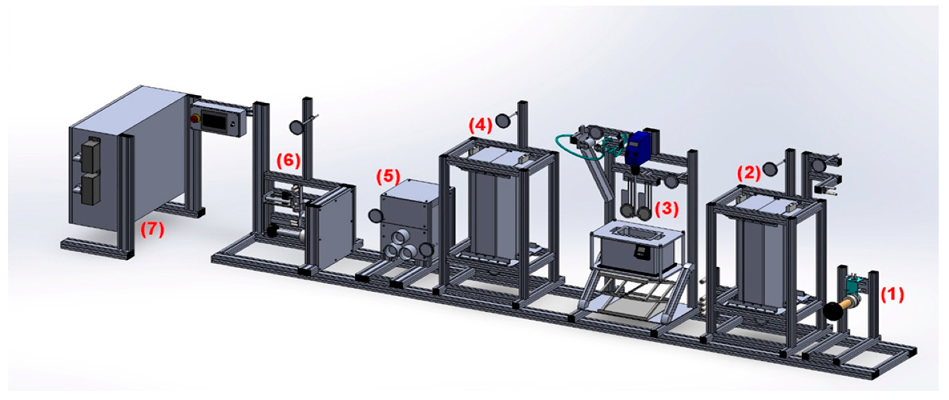
2.2. Design and Description of Pilot Line

In industry, CF sizing is a continuous process; thus, a pilot-scale continuous sizing line had to be designed for this study. The core compartments of the line were identified, and an initial sketch was drawn. IZUMI International, a company with experience in fibre line manufacturing, was selected for the line construction. The compartments were digitalized with use of SolidWorks, a CAD desktop system that provides product-level automated design tools [21]. A model was proposed that included all the core compartments and extra parts that compose the fibre sizing line (Figure 1). The latter are analysed below.
For the support frame, on which these compartments were mounted, aluminium was selected. Aluminium frame, known for its cost-effectiveness, durability, and lightweight properties, provides an optimal structural foundation for the sizing line. For the line compartments, stainless steel was the material of choice, serving multiple purposes. Its corrosion-resistant properties are particularly crucial in areas exposed to the aqueous sizing solution and traversed by the CFs. Additionally, stainless steel facilitates the smooth movement of CFs through the rollers without causing damage. Inner parts of furnaces were made of ceramic material. This material was selected for its ability to endure high temperatures and exhibit a low thermal expansion coefficient, making it well suited for the demanding conditions inherent in the sizing process. In terms of general design considerations, efforts were made to maintain adequate distances between each compartment. This design choice was driven by the aim of facilitating easy handling and maintenance for operators, emphasizing user-friendly principles throughout the engineering of fibre sizing line.
  • The let-off tension creel’s role is to feed the mounted fibre into the desizing unit and, in cooperation with the take-up winder, to provide the required tension (analysed below).
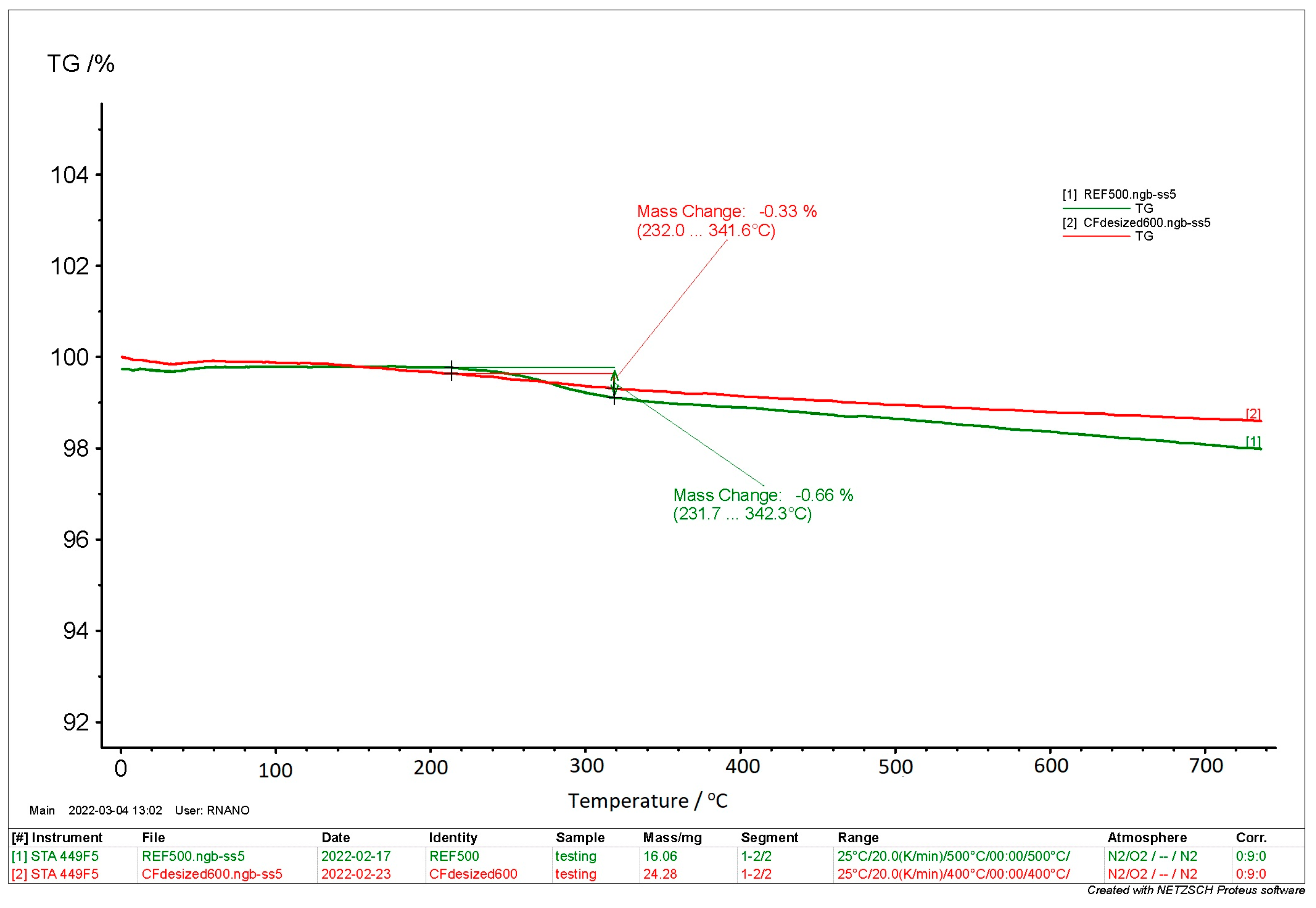
  • The desizer furnace is responsible for removal of the already existing sizing on a commercial fibre. The temperature range is wide and covers temperatures from 300 °C up to 600 °C, enabling the user to remove every unnecessary coating.
  • The fibre sizing bath consists of bath rollers, sizing bath, squeeze rollers, and an overhead stirring system. Bath rollers guide the desized fibre through the sizing bath where a solution (aqueous is the most used for CFs [22]) with users’ desired composition (solids in various concentrations) coats the fibre. The overhead steering rotor is submerged in the solution to avoid sedimentation. Subsequently, squeeze rollers remove the excess solution from the fibre so that a uniform coating is achieved.
  • As the fibre passes through the squeeze rollers and the excess is removed, fibre drying heater evaporates the remaining solvent and slightly solidifies the coating around the fibre. The temperature does not exceed 300 °C, to ensure that the coating remains intact. This process ensures that the through-thickness fibre entanglements during winding are avoided and the fibre preform is diminished (fibre needs to be fully dried before winding so that it does not retain its cylindrical shape during its unwinding).
  • The feed roller system is used to pull the fibre from the let-off creel. Its speed is adjusted by the user at the control panel (min 0.2 m/min–max 2 m/min). It is a key parameter since it affects the production rate and controls the residence time of fibre in the desizing and drying unit.
  • The take-up winder collects the fibre with a mechanical traverse system, in which the spindle is driven by a constant-torque motor. High tension is not required for fibre winding, but a specific ratio between the tension of the feed roller inlet and outlet needs to be followed. Tension is adjusted by changing the torque on control panel.
  • The power control unit supplies electric current to the whole line.

2.3. Run and Evaluation of Parameters

One of the most important aspects of this study was to pinpoint the parameters that optimize the process. For this purpose, excessive runs were completed to determine these optimum conditions (Table 4).
  • Desizer framework
Every commercially available carbon fibre is coated with a sizing agent that protects the fibre from being damaged during transport, facilitates handling during operation, and has a small effect on the fibre–resin adhesion. To assess the sizing solutions developed within this work, the already existing sizing had to be removed. The desizing furnace temperature in combination with the line’s operation speed were investigated. Six different temperatures for the desizer were chosen for the complete removal of commercial carbon fibre sizing, starting from 350 °C to 600 °C with a step of 50 °C, while the line’s operation speed varied from 0.20 to 1 and 2 m/min.
  • Dryer framework
Another important aspect as described in Section 2.2 is the effective drying of resized fibre. Similarly with the aforementioned method, three different temperatures (200, 250, 300 °C) and operation speeds (0.2, 1, 2 m/min) were tested.
  • Solid content concentration
The sizing solutions developed within this work were water dispersions with solids (HP2-06 solids and CNTs and/or FLGs). Based on previous results and the literature review [23,24,25], a nanomaterial content of 0.05, 0.1, and 0.25% wt with total solid contents (HP2-06 solids + CNTs/FLGs) of 1, 2.5, and 5% wt were examined. To produce steady aqueous solutions with HP2-06 and CNTs/FLGs, the addition of surfactants along with a sonication process had to take place.
Initially, the goal was to identify the solid concentration (without nanomaterials) that had the most uniform distribution on the fibre’s surface without any excess.
  • Nano-enhanced sizings
As mentioned above, two different nanomaterials were examined, FLGs and CNTs in different weight ratios (0.05, 0.1, and 0.25% wt) with various modifications (plasma modification with O2, N2, and NH3), resulting in 18 unique cases. The selection criteria focused on surface morphology, fibre–resin affinity, and the resulting mechanical properties.

2.4. Characterization Methods

2.4.1. Scanning Electron Microscopy (SEM) and Thermogravimetric Analysis (TGA)

The evaluation of different sizing solution parameters (solid content/nanomaterial type) on the carbon fibre’s surface was studied using an FEI Quanta 650 FEG SEM (FEI, Hillsboro, OR, USA), in magnifications up to ×10,000.
The commercial sizing that was removed during the desizing stage was evaluated also by thermogravimetric analysis using a TGA apparatus (STA 449 F5 Jupiter, Hamburg, Germany). Instrument calibration for temperature and sensitivity was performed prior to testing. Two sets of tests were performed with 16 and 24 mg of carbon fibres at a heating rate of 20 °C/min in N2 atmosphere (50 mL/min) from room temperature to 750 °C, and mass change was measured as a function of temperature. The analysis was performed in accordance with ISO 11358 [26].

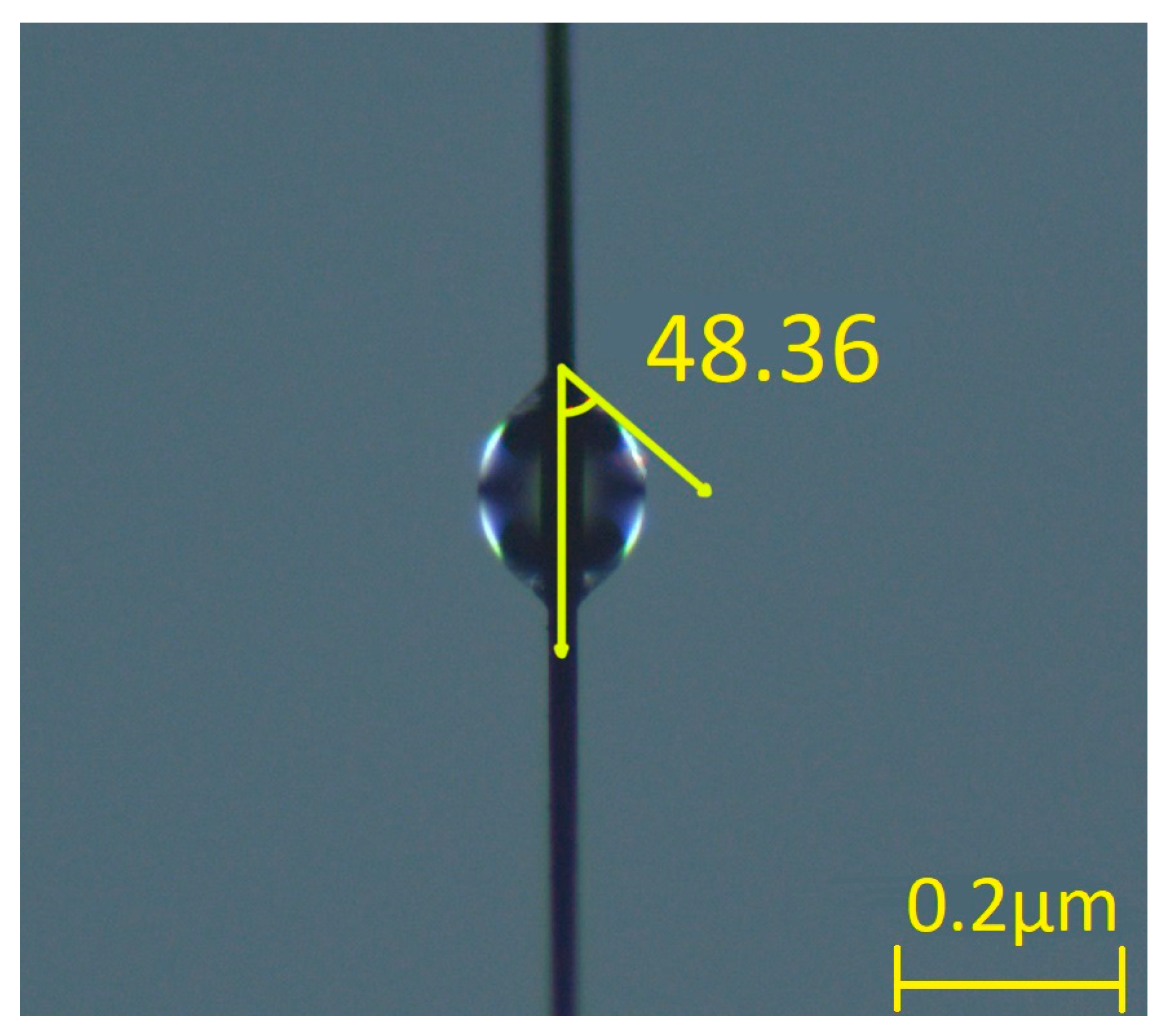
2.4.2. Contact Angle Goniometry (CAG)

The modified fibre–matrix affinity was assessed by testing single fibres, aiming to evaluate the modification’s effectiveness at microscopic level. The fibres were coated with epoxy resin type SR1710/SD8822. Each isolated fibre was placed on a Plexiglas holder. Once positioned, the fibres were coated with resin droplets using a micro-pipette and then examined by optical microscopy through a Zeiss Axio Imager A2 microscope (Carl Zeiss Microscopy, Ostfildern, Germany). For each specimen, 10 microdroplets were measured to calculate the average contact angle. Zeiss Axiovision imaging processing program was utilized to measure the inner contact angles formed between droplets and fibres. The measured angle was used as an indicator of improved wettability, with larger angles indicating enhanced wetting capabilities [27,28].

2.4.3. Mechanical Tests

For the mechanical properties, 3-point bend (3PB), tensile, and push-out tests were carried out. Regarding 3PB, the specimen was mounted between two supporting pins as loading pin force was increased progressively in the middle of the specimen, thus causing it to break. The used device was the SAUTER FH 500 with maximum load of 500 N and minimum load of 0.1 N. The loading pin’s speed was set at 3 mm/min.
To calculate flexural strength, the following formula was used:
σf = (1.5 × F × L)/(b × d2)
  • σf: flexural strength (MPa);
  • F: load at a given point on the load deflection curve (N);
  • L: support span (mm);
  • b: width of test beam (mm);
  • d: depth of tested beam (mm).
The tensile strength test was performed according to ASTM D 4018 [29]. The used specimens were tabbed resin-impregnated and consolidated fibre bundles. A universal tensile machine TE Forcespeed/Jinan WDW Series (TE Forcespeed Corporation, building 4-B-3, No.5577, Industrial North Road, Jinan, 250109, China) was used with a load cell of 5 kN.
To calculate tensile strength, the following formulas were used:
MUL = W1/L
  • MUL: mass per unit length (g/m);
  • W1: mass of the specimen (g);
  • L: length of the specimen (m).
UTS = P × ρf/MUL
  • UTS: ultimate tensile strength (MPa);
  • P: maximum load measured in tensile test (N);
  • ρf: fibre density (g/cm3);
  • MUL: mass per unit length (g/m).

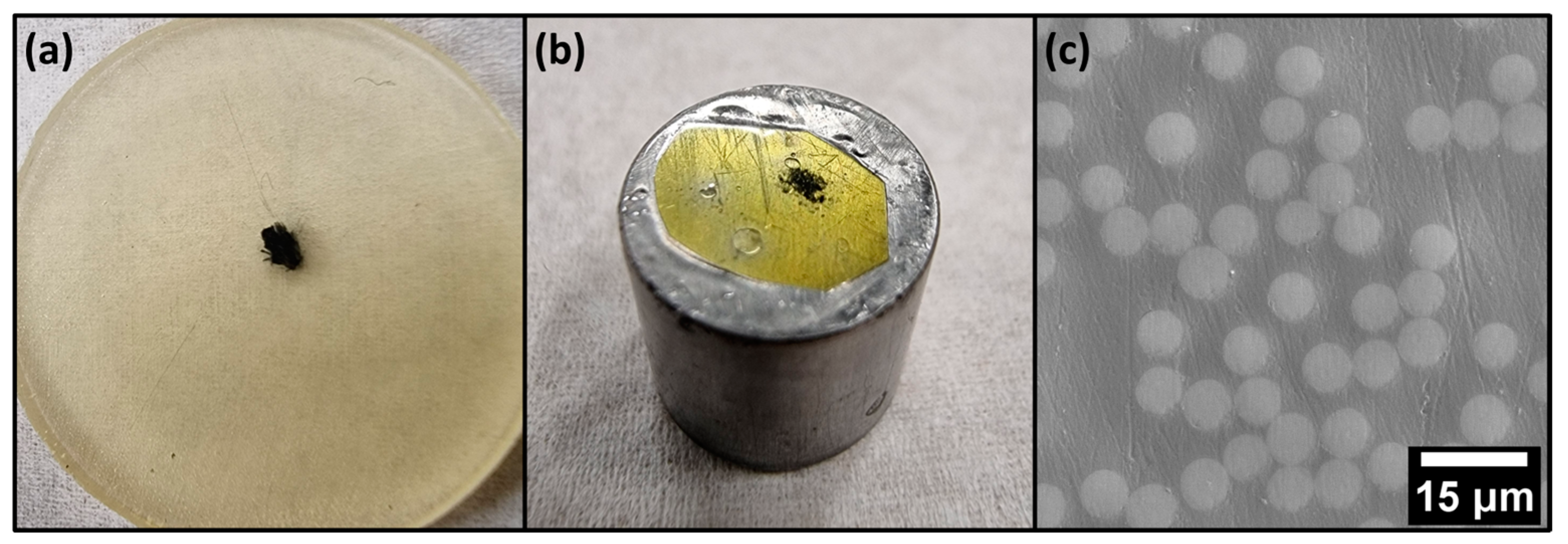
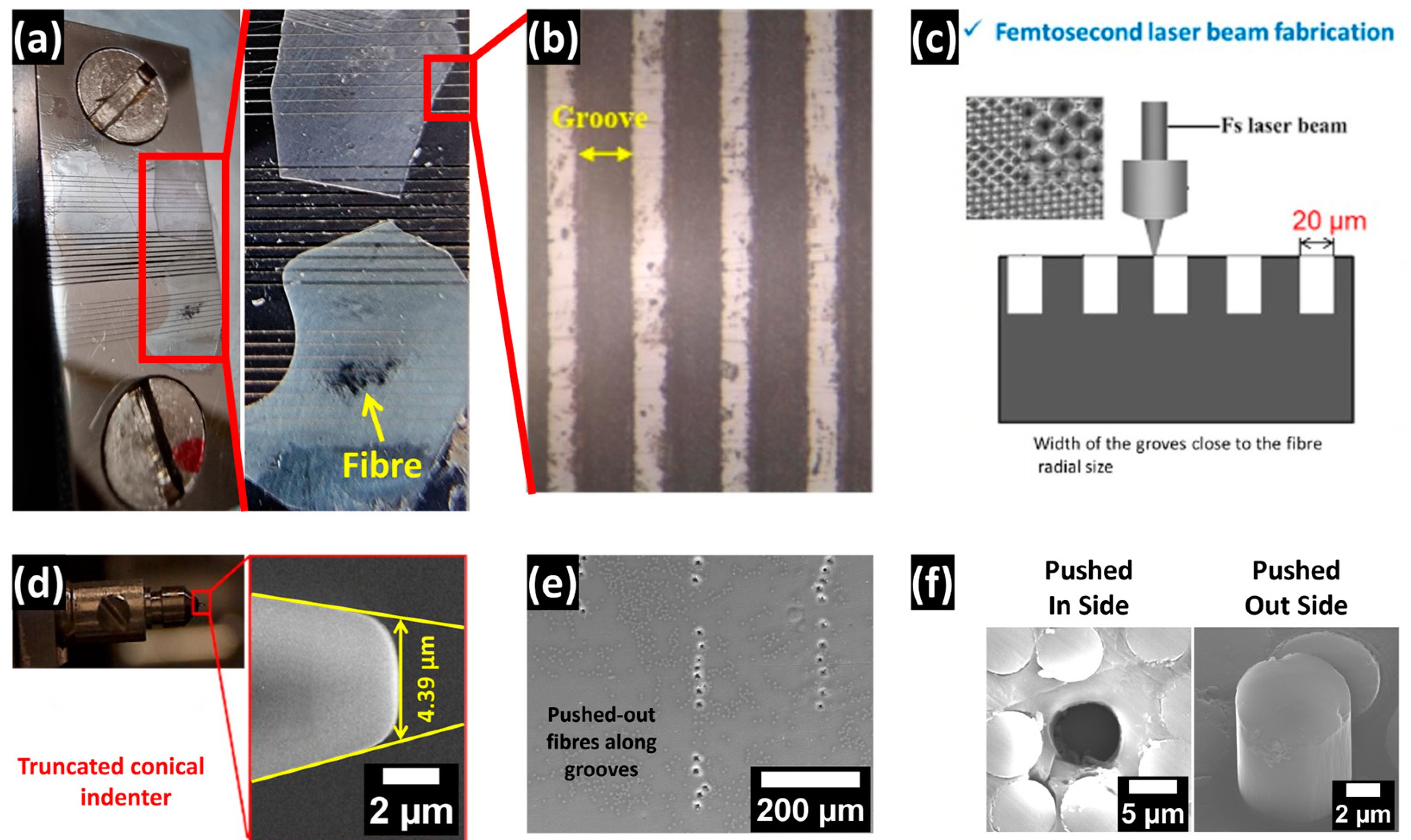
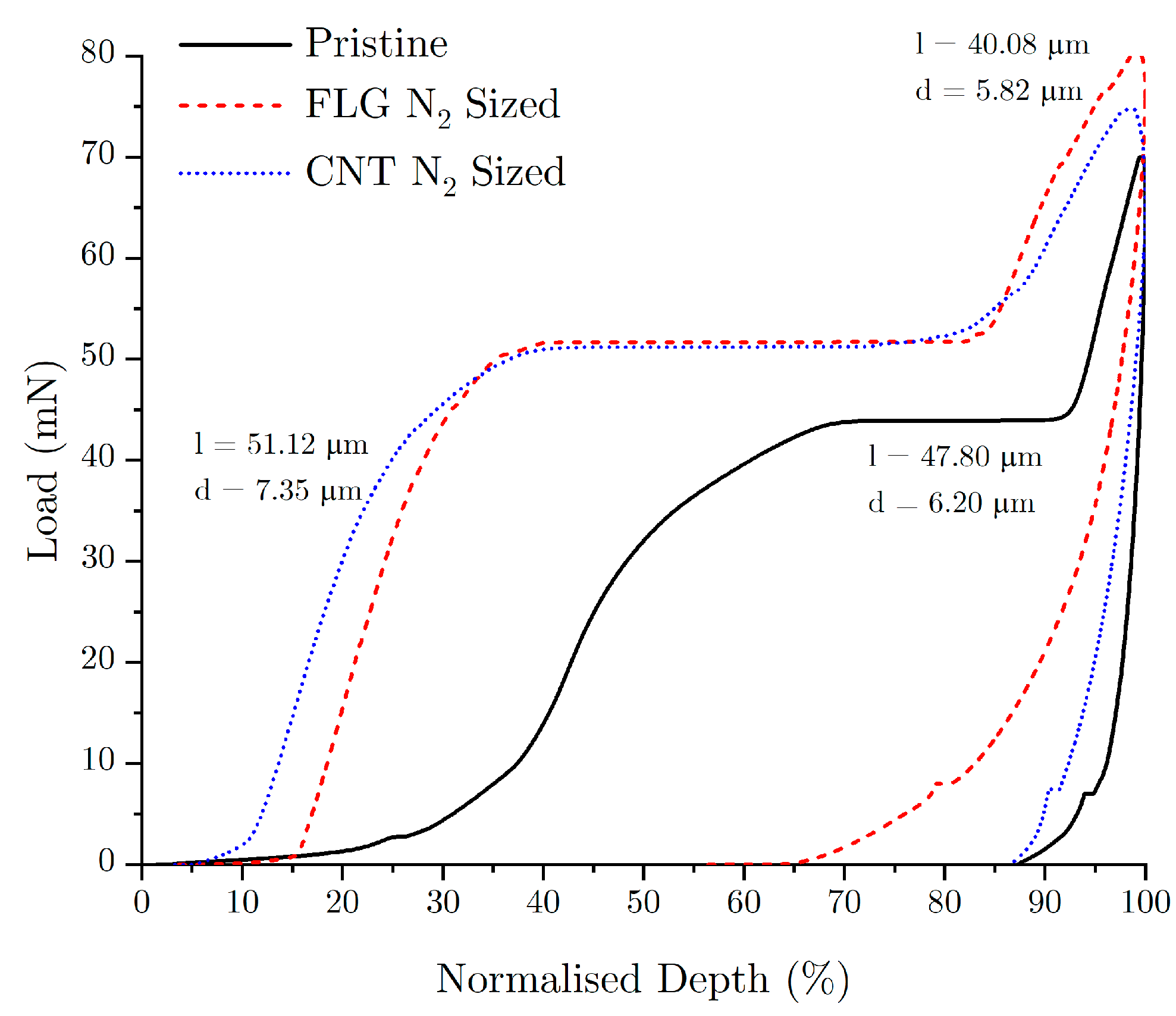
2.4.4. Push-Out Test

The interfacial shear strength (IFSS) of resin-embedded fibres was assessed using single-fibre push-out testing, where the load–displacement curve was measured when a single fibre was successfully pushed out from a resin matrix disc (of known thickness). To accurately and repeatably perform single-fibre push-out testing, thin (<55 µm) composite samples (with fibres embedded perpendicular to the polished surface) were prepared. The composite’s matrix consisted of a mixture of EPIKOTE™ Resin MGS RIMR 135 resin and 4-aminophenyl disulfide hardener in a ratio of 100 g (resin) to 55.051 g (hardener). The hardener was initially melted by heating at 80–85 °C (SNOL 3/1100 muffle furnace) before the resin was added. The fibres were then held under tension within silicone rubber moulds (1-inch diameter, Agar Scientific Ltd., Stansted, UK) before being embedded in the resin and hardener mixture. The composite mixture was then cured by heating at 130 °C for 1.5 h (SNOL 3/1100 muffle furnace). Thin discs (~1 mm) were abrasion-cut from initial composite and then ground to reduce disc thickness to a few hundred microns, using #4000 grit SiC abrasive paper. The surface of the thin slices was polished to a mirror finish (Struers OP-S) and then attached (using wax) onto a GATAN TEM sample disc grinder. The other surface was used to thin the composite discs to an approximate thickness of 30–50 µm (using #4000 grit SiC paper and 1 µm diamond suspension). A final polish (Struers OP-S) of both surfaces of the composite discs was carried out and then assessed using optical imaging (Figure 2). The final composite discs were then glued (Loctite Superglue Precision) to a metal support with 20 µm wide grooves (which provide the necessary depth needed for pushing out the fibres) produced by femtosecond-laser fabrication (Figure 3).
Single-fibre push-out tests were performed using NanoTest Vantage (Micro Materials Ltd., Wrexham, UK) nanomechanical instrument fitted with a conical diamond indenter with a maximum tip diameter of 4.39 µm (Figure 3). To more accurately record the applied load and to precisely aim the indenter tip, both load and cross-hair calibration of the instrument were performed on regions of the composite disc above grooves and with no fibres present. Testing was performed by manually choosing ideal single fibres (i.e., with no damage and within the grooves) using a 400× optical microscope attached to NanoTest device. Disc thickness was locally measured at each site by recording physical travel distance from the focus point on the metal support to the surface point on the composite. Testing was performed under loading and unloading rates of 0.5 mN/s, with a dwell time of 5 s at the final load.
The load–displacement curves for each push-out test were analysed to confirm the successful pushing-out of fibre without significant prior crack formation or damage to the fibre or disc. Finally, the composite discs were removed from the metal support (using ethanol) and imaged (JEOL 7000F FEG SEM). Only push-out data corresponding to a well-centred contact and with intact fibres (i.e., not crushed) were used for subsequent IFSS calculations (Figure 3).
The IFSS was calculated by examining the load for complete debonding of the fibre–resin matrix interface (sudden change in displacement with no increase in load) using the following equation:
τ = F/(π × d × l)
  • τ: IFSS between fibre and resin (Pa);
  • F: push-out load (N);
  • d: diameter of the pushed-out fibre (m);
  • l: length of the fibre being pushed out (m).

3. Results

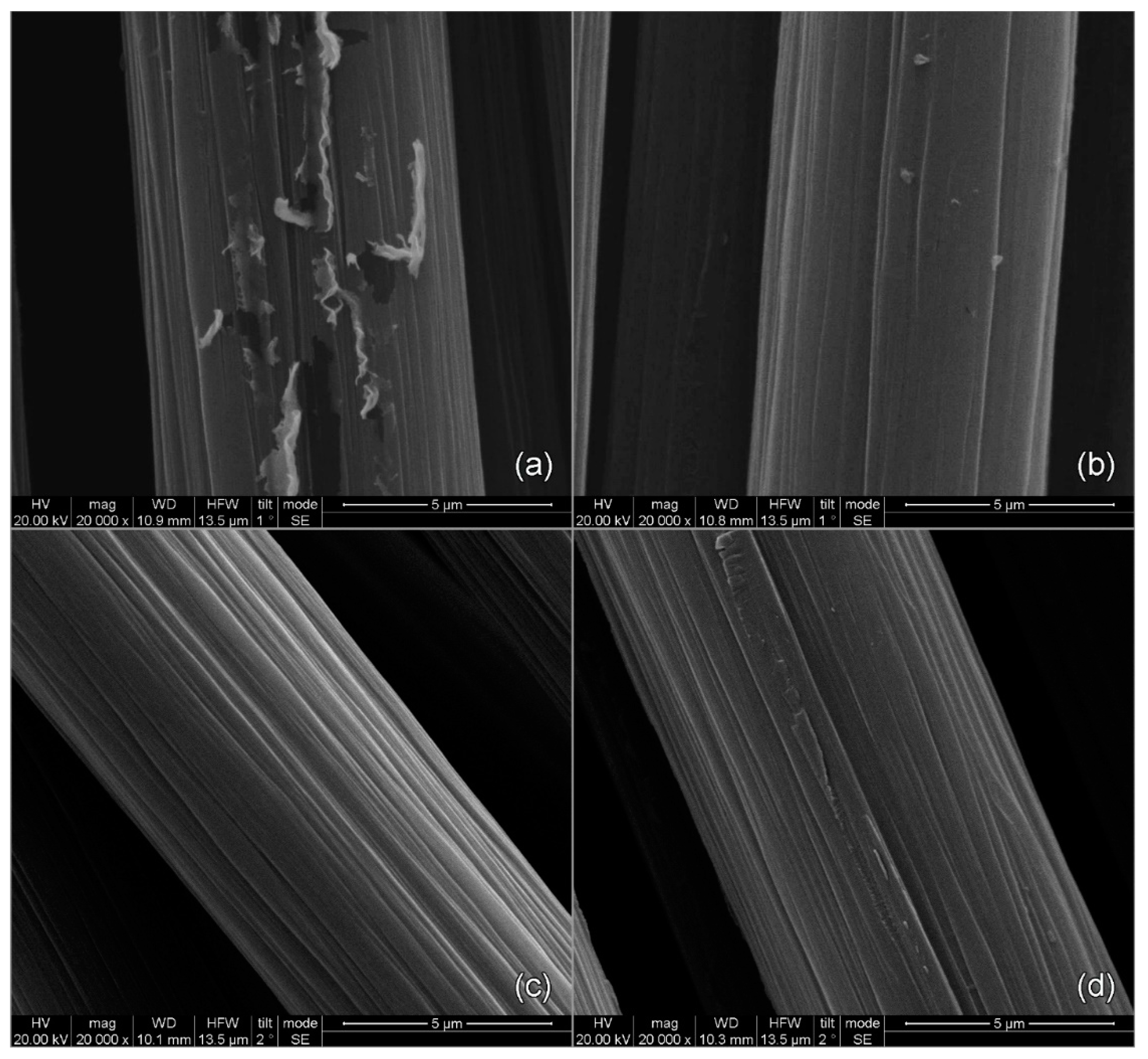
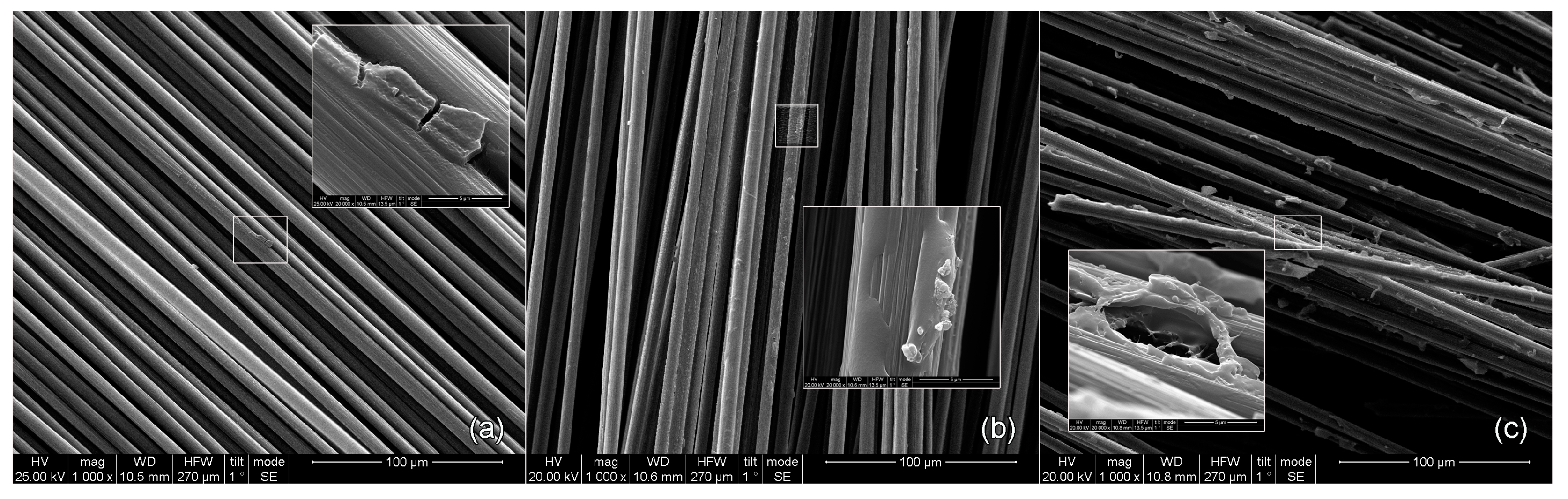
3.1. De-Sizing/Drying Temperatures

As mentioned before, the temperature of the furnaces and the residence time of CFs inside these furnaces are two of the most important factors that the affect efficiency and productivity of the sizing line, as both parameters impact the effective removal of sizing. Higher temperatures facilitate the process, but they might have a negative impact on the fibre’s properties. On the other hand, a longer residence time can accelerate sizing removal, though it reduces the production rate (lower-speed line results in fewer meters treated per hour). The parametric study that follows assesses the parameters that ensure effective desizing temperatures with a higher production rate.
Operation speeds of 0.2, 1, and 2 m/min correspond to 18 s and 1 and 2 min of residence time. For this purpose, six different temperatures for the desizer were tested, starting from 350 °C to 600 °C with a step of 50 and for the three different dryer temperatures (200/250/300 °C). The line’s operation speed was set to the lowest possible, 0.2 m/min, that correlates with 18 s for the residence time of CFs inside the furnaces. The results from SEM analysis of these runs are depicted in Figure 4.
Evidently, temperatures of 350 and 400 °C have an effect on the CF’s surface, as can be observed from Figure 4a,b. The pre-existing polymeric sizing starts to degrade and debond from the fibre surface. This indicates that the residence time is not long enough or there is not enough energy derived from heat (due to low temperature) to entirely remove the coating. The desizing phenomenon intensifies at temperatures of 450 and 500 °C, where it is obvious from Figure 4c,d that a large amount of the thin polymeric film is detached from the surface, leaving the exposed CF area available for new sizing. However, it is only at temperatures of 550 and 600 °C that the CF surface area is totally exposed, as the preexisting sizing is completely removed.
To accelerate the desizing process and increase the production rate, lower but efficient values of residence time were put to test. Additional runs were executed at 550 and 600 °C (Figure 5) in which two values of residence time were tested (18 s and 1 min).
Regardless of residence time, 600 °C is sufficient to efficiently remove all the pre-existing sizing. At 550 °C, 1 min of heating is required, due to some polymeric residues that may be observed on the CF surface, as proved from the tests performed with 18 s of residence time. As a conclusion, to achieve the highest production rate of the sizing line, a desizing temperature of 600 °C is required, as the line can operate in 2 m/min. The results from mechanical tests would determine if 600 °C affects the properties of the fibres. If the mechanical properties decrease, then an operational speed of 1 m/min must be implemented using 550 °C as the desizing temperature.
TGA was used to study the thermal decomposition of the commercially sized and desized CFs to validate the SEM results.
In graphs like those presented in Figure 6, where mass change differences are considerably low, it is quite challenging to extract solid quantitative conclusions. In this case, the graph form is of great interest and is the one that provides all necessary information. As highlighted in the temperature ranges of 231.7 to 342.3 °C for the reference fibres, there is a steep change in the form of the graph, a sudden drop that is attributed to decomposition, evaporation, or other chemical reactions. In our case, it is decomposition of the pre-existing sizing. On the contrary, for the desized fibre, there is no similar phenomenon, besides the normal negligible mass loss over time, indicating that the pre-existing sizing is removed during the desizing process, confirming what was already assessed from SEM analysis.
Finally, an operation speed of 1 or 2 m/min must be taken into consideration for the effective drying of CFs. As indicated by the desizing investigation, these two operation speeds will give the highest productivity. The drying furnace can reach temperatures up to 300 °C, so test runs at 200; 250 and 300 °C at operational speeds of 1 and 2 m/min were executed. As the fibre exited the furnace, filter papers were used to detect the moisture level. At 200 °C and regardless of operation speed, the filter paper was wet. At 250 °C, and at an operation speed of 1 m/min, the filter paper was dry. Evidently, at 300 °C, the carbon fibre was also completely dry for every operation speed.
To conclude, for a desizing temperature of 550 °C and drying temperature of 250 °C, the maximum operation speed was 1 m/min, whereas for a desizing temperature of 600 °C and drying temperature of 300 °C, the sizing line could work at full speed, 2 m/min, without any drawbacks.

3.2. Solid Content Concentration

A uniform distribution of sizing solids onto the CF surface ensures the functionality of this polymeric layer, which facilitates fibre handling and affects mechanical properties. Solid excess could potentially hinder the solution’s adhesion to the CF. A thicker layer would act as an extra layer instead of an interlayer, which would improve the affinity of the CF with the resin matrix system. Alternatively, a thinner layer might fail to provide adequate protection during handling and mechanical reinforcement. Achieving the ideal solid content concentration in the sizing solution and subsequently on the CF surface is essential for the utilization of the sizing system. SEM analysis provided information regarding solid content percentages of 1, 2.5, and 5% wt, aiding in the identification of the optimal ratio (Figure 7).
At the 1% wt solid content level, the coating’s performance displayed uniformity across the total carbon fibre surface. CF stripes were visible, without any local solid excess spots. In contrast, when the solid content was elevated to 2.5% and 5% wt, it was noticeable that the desired uniformity was nonexistent. The increase in solid content led to an uneven distribution and the creation of excess mass, impacting the coating’s ability to uniformly adhere to the carbon fibre surface. As a result, the 1% wt solid content coating stood out as the optimal choice, ensuring even distribution and thickness.

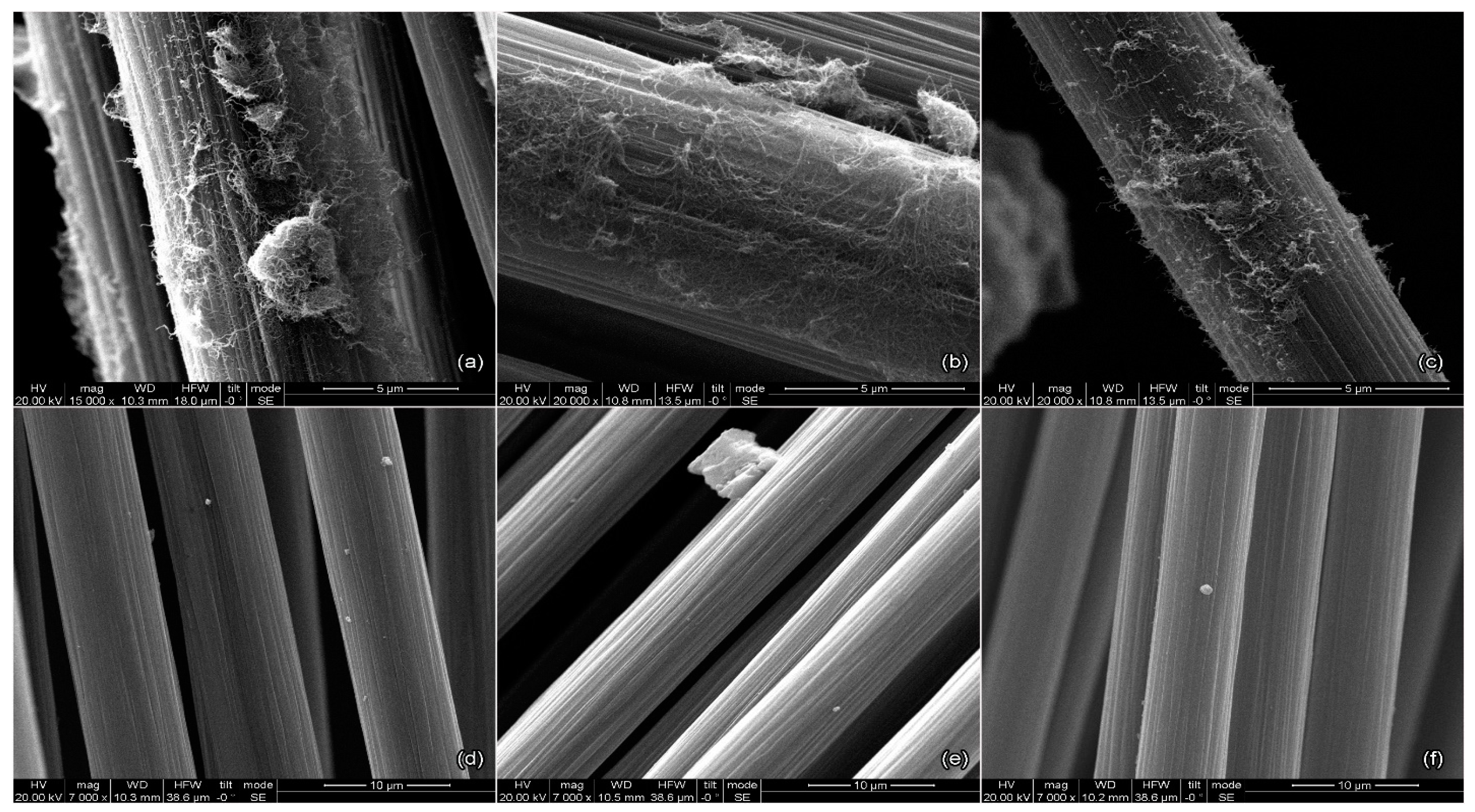
3.3. Nanoenhanced Sizings

Based on the findings from Section 3.2, a total solid content concentration of 1% wt was identified as the optimal choice, demonstrating an ideal layer thickness and uniform coverage across the CF surface. To study the potential use of nanomaterials in sizing solutions, CNT- and FLG-sized fibres were examined in terms of surface morphology through SEM. To define their optimum concentration in sizing solutions, the affinity of CFs with resin was assessed through CAG and the mechanical performance was assessed through tensile, 3PB, and push-out testing.

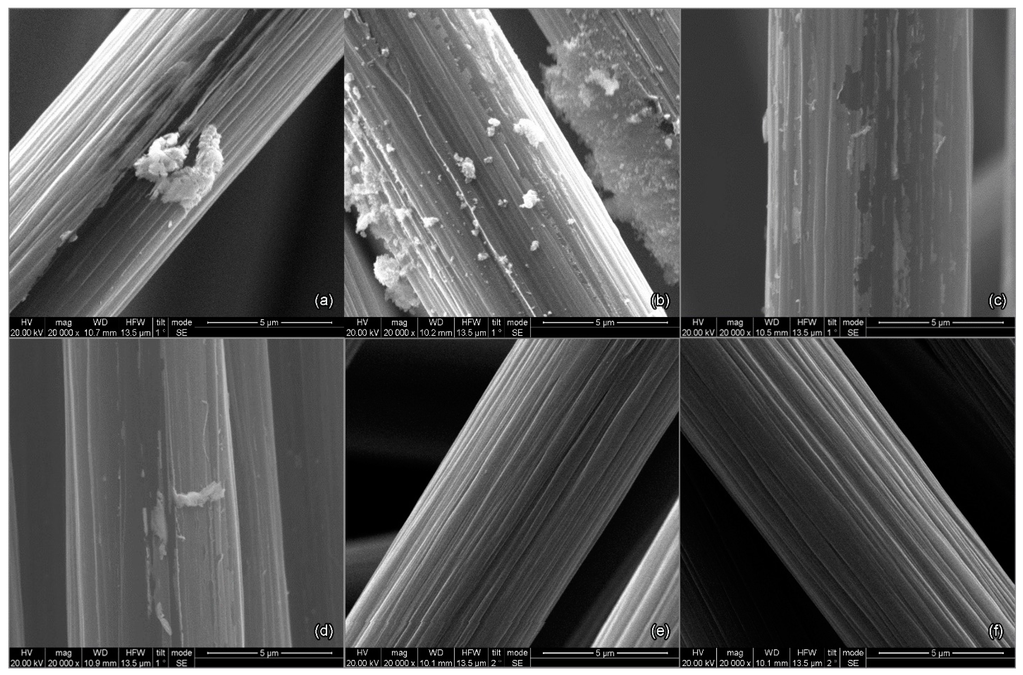
3.3.1. Surface Morphology Assessment

In the case of CNTs, this investigation focused on assessing layer uniformity and nanomaterial agglomeration and distribution across the CF’s surface. On the other hand, due to the unique dimensions of FLGs, SEM analysis was primarily focused on uniformity, as conventional metrics of agglomeration and distribution cannot be applied. Analysis was performed on samples with 0.25% wt CNTs or FLGs out of the three weight ratios under investigation (0.05, 0.1, 0.25% wt) and all three possible functionalizations (O2, NH3, N2), resulting in studying six different cases.
Taking into consideration Figure 8, the addition of CNTs in the sizing solutions does not appear to have a negative impact on the sizing layer uniformity, with no observation of sizing pile-up, the presence of boundaries, or delamination of the sizing layer following the CNT and FLG sizing treatments. This suggests that the sizing layer is uniformly distributed across the surface with no unsized or excessively sized spots. However, some potential drawbacks that can be derived from SEM analysis are related to the formation of agglomerates, especially for the cases of O2 and NH3 plasma-functionalized CNTs deposited on fibres. The nanomaterial distribution on the fibre surface is inconsistent, displaying specific localized areas with varying nanomaterial concentrations, alongside spots with minimal or absent nanomaterial presence.
Addressing these drawbacks demands extensive further study. Specifically, understanding the interactions among the three different plasma-functionalized particles and the sizing solution is crucial, offering insights into mitigating the inconsistent distribution on the fibre surface and the formation of agglomerates. Initial enhancements could be achieved by investigating the duration for which a stable solution can be maintained during the preparation of the sizing solution, without the occurrence of agglomerates or sediment formation. Mechanical tests would determine whether these drawbacks have a significant effect on the properties of the fibres. FLGs appeared to exhibit a highly uniform distribution without spots of inconsistency.

3.3.2. Fibre–Resin Affinity

The importance of affinity in composites made of carbon fibre and resin is critical as it signifies the strength of the bond between them, significantly impacting the material’s performance and durability. Good affinity facilitates load transfer and enhances mechanical properties. It also contributes to the material’s resistance to environmental factors, thermal cycling, and fatigue [26].
Table 5 represents the average contact angle as measured in the Zeiss Axiovision 4.9 imaging processing software (Figure 9). It can be observed that the desized fibre exhibits a contact angle of 46.1°, while the contact angle for all the different functionalizations seems to be smaller, resulting in better wettability. The greatest decrease is observed for samples with N2 functionalization for both CNTs and FLGs, with contact angle reductions of 7.6% and 13.4%, respectively.
The contact angle results for CNT-sized fibres are in agreement with Section 3.3.2, where fewer agglomerates are observed for the case of CNT-N2-sized fibres, indicating a potential correlation between fibre–resin affinity and nanomaterial agglomerates.

3.3.3. Mechanical Performance

Three-Point-Bend and Tensile Results

Initially, samples were subjected to tensile and 3PB tests to assess any potential impact of the sizing process and its steps (e.g., desizing, drying, winding) on the mechanical properties of fibres. For example, desizing is a process step performed at relatively high temperatures (600 °C); thus, it is important to investigate its effect on fibre performance and compare it with data retrieved from the literature. Tensile strength is a property that is mostly dependent on the Young’s modulus of the material. Despite sizing not altering the Young’s modulus of the fibre, it can promote the fibre–matrix adhesion, which is another parameter that contributes to a material’s tensile strength [28,30]. A potential increase in the tensile strength could be related to the latter, especially in the case with nano-enhanced sizing, indicating some cases with improved properties.
A correlation of the results from mechanical tests with those from morphology and affinity assessments is the validation mechanism and decision tool to promote the cases for push-out testing. The push-out test is the optimal method to define the interfacial shear strength of sized fibres, a property which is highly related to the fibre–matrix adhesion.
Upon comparing the results presented in Table 6 for desized fibres and Michelman-sized fibres, it is evident that the latter outperformed in both tensile and 3PB strength. This improvement can be attributed to the sizing’s ability to neatly rearrange the fibres and reduce disorientation [31,32].
In the 3PB test among the three different plasma functionalizations and weight ratios, 0.1% N2-CNT-sized fibres and 0.1% N2-FLG-sized fibres stood out with the best results, 44.5 ± 3 MPa and 45.1 ± 2.8 MPa accordingly. On the other hand, the desized fibres exhibited the lowest strength, 31.3 ± 3 MPa, as expected.
In the tensile test, and in agreement with the 3PB data, 0.1% N2-CNT-sized fibres and 0.1% N2-FLG-sized fibres exhibited the highest tensile strengths of 434 ± 12 MPa and 444 ± 39 MPa, respectively. The desized fibres showed again the lowest tensile strength, measuring at 262 ± 31 MPa.
O2-CNT-sized fibres and NH3-CNT-sized fibres exhibited less favourable or similar results to Michelman-sized fibres. This can be attributed to the presence of CNT agglomerates on the fibre surface which can suspend the beneficial effect of CNTs on the fibre–matrix adhesion. These agglomerates pose challenges for interfacial properties and may potentially introduce stress concentration points during loading, which can impact the mechanical performance [33].
Evidently, 0.1% N2-CNT-sized fibres and 0.1% N2-FLG-sized fibres consistently yielded superior results in both the 3-point bend and tensile tests, while maintaining a uniform coating. These results are in agreement with those from SEM analysis where agglomeration was observed for O2-CNT-sized fibres and NH3-CNT-sized fibres, and the CAG findings where the optimum affinity was with N2-CNT-sized fibres and N2-FLG-sized fibres.
The enhanced performance of N2-functionalized nanoparticles can be attributed to their chemical affinity with the sizing solution. As shown in Table 2, HP206 is amine-dispersed, while N2 functionalization introduces C-N bonds, as confirmed by XPS results (see Supplementary File). The incorporation of C-N bonds contributes to a stronger chemical affinity compared to O2 functionalization, which introduces C-O bonds. Although NH3 functionalization also introduces C-N bonds, the quantity is considerably lower than in N2 functionalization (area of C-N bond in C1s scan: 4.1% for NH3 FLG compared to 4.7% for N2 FLGs and 0.49% for NH3 CNTs compared to 1.78% for N2 CNTs). This variation accounts for the superior overall properties associated with N2 functionalization.
Based on these results, 0.1% N2-CNT-sized fibres and 0.1% N2-FLG-sized fibres were examined under push-out tests to determine their influence on the interfacial shear properties of composites.

Push-Out Test Results

Three groups of composites were produced for IFSS evaluation, consisting of pristine, 0.1% N2-CNT-sized fibres, and 0.1% N2-FLG-sized fibres embedded within resin matrices. The reported IFSS measurements in Table 7 correspond to data from undisturbed push-out tests (i.e., fibres pushed out smoothly in one go and without damage to the fibres). A clear increase in IFSS can be seen following the FLG N2 and CNT N2 sizing treatments of the fibres, with an increase from 50.3 ± 5.5 MPa (pristine) to 70.7 ± 2.9 MPa and 95.4 ± 7.6 MPa, respectively. As compared with the pristine fibres, this constitutes an IFSS increase of 40.6% and 89.7% for the respective treated fibres. Figure 10 illustrates example hysteresis data of each composite type during the single-fibre push-out testing. Both treated fibres are found to exhibit significantly greater loading rates (gradient before the push-out event), thus reaching the push-out load at approximately half the normalised depth as the pristine fibre. This demonstrates the more efficient transfer of load between the indenter and the fibre interface, leading to a more minimal deflection of the resin matrix during loading. The most significant enhancement is found with the CNT N2 treatment, which is observed to have the best structural rigidity and IFSS within this study.

4. Conclusions

In this study, a pilot-scale sizing line for carbon fibres was designed and installed, serving as an established tool for extensive investigation. Various operational parameters were thoroughly explored to optimize the line’s performance and productivity. A key parameter was the necessity of desizing temperature for commercial fibres. This research demonstrated that a desizing temperature of 600 °C was essential to achieve maximum productivity, ensuring complete removal of the pre-existing sizing agents and enabling the line to operate at its peak efficiency.
Detailed surface morphology analysis, conducted through SEM, confirmed the significance of maintaining a 1% solid content in the coating solution. This specific concentration was identified as the optimum choice, ensuring uniformity and appropriate film thickness on the carbon fibre surface. This study then focused on the integration of nanomaterials, such as carbon nanotubes and few-layer graphene, aiming to enhance mechanical performance. This research highlighted the importance of good affinity between these nanomaterials and the fibres through contact angle tests, a critical factor influencing the strength and durability of the resulting composites.
The mechanical tests indicated improved and desirable properties for the treated fibres, emphasizing the effectiveness of optimized parameters. This study further employed push-out tests, revealing substantial improvements in the interfacial shear strength of 89.7% for 0.1% N2-CNT-sized fibres and 40.6% for 0.1% N2-FLG-sized fibres, as compared to the reference fibres, thereby demonstrating enhanced bonding between fibres and the surrounding matrix.
The improved chemical affinity of the sizing solution (amine-dispersed) with N2-functionalized CNTs/FLGs is attributed to the addition of C-N bonds, surpassing both (a) the C-O bonds introduced by O2 plasma functionalization and (b) the quantity of C-N bonds in NH3 plasma functionalization.
In conclusion, the outcomes of this research underline the significant potential for tailoring sizing solutions to match specific requirements. By utilizing the pilot-scale sizing line, besides the scientific finding this study reveals, a practical tool for developing customized sizing solutions is also provided. These findings encourage the exploration of tailored sizing solutions, contributing to the advancement of understanding in this complex domain, enabling innovative applications in the field of composite materials.

Supplementary Materials

The following supporting information can be downloaded at https://www.mdpi.com/article/10.3390/fib12020016/s1, Figure S1: FLG 0.1% wt water dispersions; Figure S2: CNTs 0.1% wt water dispersions; Figure S3: 3510 BRANSON sonication bath (left) and Thielsen ultrasonic processor (right); Figure S4: Samples 24 h after sonication for 1 h in 3510 BRANSON sonication bath; Figure S5: Samples after ultrasonication with Thielsen sonication probe at 72 h; Figure S6: FLG unfunctionalized; Figure S7: FLG NH3; Figure S8: FLG N2; Figure S9: FLG O2; Figure S10: CNT unfunctionalised; Figure S11: CNT NH3; Figure S12: CNT N2; Figure S13: CNT O2; Table S1: Table of surfactants that were tested; Table S2: Samples prepared for step 1; Table S3: Samples prepared for step 2; Table S4: XPS element survey results of unfunctionalised and functionalised nanomaterials; Table S5: XPS high-resolution data peak assignment FLG materials; Table S6: XPS high-resolution data peak assignment CNT materials.

Author Contributions

Conceptualization, D.S.; methodology, D.S., I.P., S.A., B.D. and X.L.; investigation, D.S., I.P., S.A., B.D. and X.L.; writing—original draft preparation, D.S., I.P., B.D. and X.L.; writing—review and editing, D.S., H.D. and C.A.C.; visualization, D.S.; supervision, H.D. and C.A.C.; funding acquisition, C.A.C. All authors have read and agreed to the published version of the manuscript.

Funding

This research was funded by the EU H2020 project “New generation of offshore turbine blades with intelligent architectures of hybrid, nano-enabled multi-materials via advanced manufacturing” (Carbo4Power), under Grant Agreement no. 953192.

Data Availability Statement

Data will be available on the Zenodo platform upon request.

Acknowledgments

The authors would like to thank Haydale Ltd. for the supply of functionalized nanomaterials and XPS measurements and Maria Modestou for the preparation of graphical abstract.

Conflicts of Interest

The authors declare no conflicts of interest.

References

  1. Becker-Staines, A.; Bremser, W.; Tröster, T. Cyclodextrin as sizing for carbon fibers: New bonding mechanism improves adhesion in carbon fiber reinforced epoxy resin. Heliyon 2020, 6, e03766. [Google Scholar] [CrossRef]
  2. Wu, Q.; Zhao, R.; Xi, T.; Yang, X.; Zhu, J. Comparative study on effects of epoxy sizing involving ZrO2 and GO on interfacial shear strength of carbon fiber/epoxy composites through one and two steps dipping routes. Compos. Part A Appl. Sci. Manuf. 2020, 134, 105909. [Google Scholar] [CrossRef]
  3. Rankin, S.M.; Moody, M.K.; Naskar, A.K.; Bowland, C.C. Enhancing functionalities in carbon fiber composites by titanium dioxide nanoparticles. Compos. Sci. Technol. 2021, 201, 108491. [Google Scholar] [CrossRef]
  4. Lim, S.H.; On, S.Y.; Kim, H.; Bang, Y.H.; Kim, S.S. Resin impregnation and interfacial adhesion behaviors in carbon fiber/epoxy composites: Effects of polymer slip and normalized surface free energy with respect to the sizing agents. Compos. Part A Appl. Sci. Manuf. 2021, 146, 106424. [Google Scholar] [CrossRef]
  5. Eyckens, D.J.; Arnold, C.L.; Simon, Ž.; Gengenbach, T.R.; Pinson, J.; Wickramasingha, Y.A.; Henderson, L.C. Covalent sizing surface modification as a route to improved interfacial adhesion in carbon fibre-epoxy composites. Compos. Part A Appl. Sci. Manuf. 2021, 140, 106147. [Google Scholar] [CrossRef]
  6. Chu, C.; Ge, H.; Gu, N.; Zhang, K.; Jin, C. Interfacial microstructure and mechanical properties of carbon fiber composite modified with carbon dots. Compos. Sci. Technol. 2019, 184, 107856. [Google Scholar] [CrossRef]
  7. Wang, S.; Yang, Y.; Mu, Y.; Shi, J.; Cong, X.; Luan, J.; Wang, G. Synergy of electrochemical grafting and crosslinkable crystalline sizing agent to enhance the interfacial strength of carbon fiber/PEEK composites. Compos. Sci. Technol. 2021, 203, 108562. [Google Scholar] [CrossRef]
  8. Ali, I.; Shchegolkov, A.; Shchegolkov, A.; Chumak, M.A.; Viktorovich, N.A.; Vasilievich, L.K.; Imanova, G.; Kurniawan, T.A.; Habila, M.A. Facile microwave synthesis of multi—Walled carbon nanotubes for modification of elastomer used as heaters. Polym. Eng. Sci. 2023, 63, 3975–3985. [Google Scholar] [CrossRef]
  9. Zhang, Z.; Li, X.; Jestin, S.; Termine, S.; Trompeta, A.-F.; Araújo, A.; Santos, R.M.; Charitidis, C.; Dong, H. The Impact of Carbon Nanofibres on the Interfacial Properties of CFRPs Produced with Sized Carbon Fibres. Polymers 2021, 13, 3457. [Google Scholar] [CrossRef]
  10. Yuan, C.; Li, D.; Yuan, X.; Liu, L.; Huang, Y. Preparation of semi-aliphatic polyimide for organic-solvent-free sizing agent in CF/PEEK composites. Compos. Sci. Technol. 2021, 201, 108490. [Google Scholar] [CrossRef]
  11. Yuan, X.; Jiang, J.; Wei, H.; Yuan, C.; Wang, M.; Zhang, D.; Liu, L.; Huang, Y.; Gao, G.-L.; Jiang, Z. PAI/MXene sizing-based dual functional coating for carbon fiber/PEEK composite. Compos. Sci. Technol. 2021, 201, 108496. [Google Scholar] [CrossRef]
  12. Michelman.com. Reinforced Plastic Composites-Fibre SizingReinforced Plastic Composites-Fibre Sizing. Available online: https://www.michelman.com/markets/reinforced-plastic-composites/fibre-sizing/ (accessed on 3 November 2023).
  13. Li, M.; Gu, Y.; Liu, Y.; Li, Y.; Zhang, Z. Interfacial improvement of carbon fiber/epoxy composites using a simple process for depositing commercially functionalized carbon nanotubes on the fibers. Carbon 2013, 52, 109–121. [Google Scholar] [CrossRef]
  14. Sharma, M.; Gao, S.; Mäder, E.; Sharma, H.; Wei, L.Y.; Bijwe, J. Carbon fiber surfaces and composite interphases. Compos. Sci. Technol. 2014, 102, 35–50. [Google Scholar] [CrossRef]
  15. Knoll, J.; Riecken, B.; Kosmann, N.; Chandrasekaran, S.; Schulte, K.; Fiedler, B. The effect of carbon nanoparticles on the fatigue performance of carbon fibre reinforced epoxy. Compos. Part A Appl. Sci. Manuf. 2014, 67, 233–240. [Google Scholar] [CrossRef]
  16. Haydale Ltd. Creating Material Chang. 2019. Available online: https://haydale.com/wp-content/uploads/2023/03/Haydale_Brochure_Functionalised_Graphene.pdf (accessed on 11 November 2023).
  17. Evgeniy, T.E.; Marcos, G.; Gijsbertus, D.W.; Cor, K.E. The use of surfactants for dispersing carbon nanotubes and graphene to make conductive nanocomposites. Curr. Opin. Colloid Interface Sci. 2012, 17, 225–232. [Google Scholar]
  18. Sezer, N.; Koc, M. Stabilization of the aqueous dispersion of carbon nanotubes using different approaches. Therm. Sci. Eng. Prog. 2018, 8, 411–417. [Google Scholar] [CrossRef]
  19. Rastogi, R.; Kaushal, R.; Tripathi, S.K.; Sharma, A.L.; Kaur, I.; Bharadwaj, L.M. Comparative study of carbon nanotube dispersion using surfactants. J. Colloid Interface Sci. 2008, 328, 421–428. [Google Scholar] [CrossRef] [PubMed]
  20. Keinänen, P.; Siljander, S.; Koivula, M.; Sethi, J.; Sarlin, E.; Vuorinen, J.; Kanerva, M. Optimized dispersion quality of aqueous carbon nanotube colloids as a function of sonochemical yield and surfactant/CNT ratio. Heliyon 2018, 4, e00787. [Google Scholar] [CrossRef] [PubMed]
  21. Zhang, H.-Y.; Li, T.-C.; Li, Z.-K. Modeling in SolidWorks and analysis of temperature and thermal stress during construction of intake tower. Water Sci. Eng. 2009, 2, 95–102. [Google Scholar] [CrossRef]
  22. Tiwari, S.; Bijwe, J. Surface Treatment of Carbon Fibers—A Review. Procedia Technol. 2014, 14, 505–512. [Google Scholar] [CrossRef]
  23. Körbelin, J.; Kötter, B.; Voormann, H.; Brandenburg, L.; Selz, S.; Fiedler, B. Damage tolerance of few-layer graphene modified CFRP: From thin-to thick-ply laminates. Compos. Sci. Technol. 2021, 209, 108765. [Google Scholar] [CrossRef]
  24. Hao, B.; Ma, Q.; Yang, S.; Mäder, E.; Ma, P.-C. Comparative study on monitoring structural damage in fiber-reinforced polymers using glass fibers with carbon nanotubes and graphene coating. Compos. Sci. Technol. 2016, 129, 38–45. [Google Scholar] [CrossRef]
  25. Lai, M.; Jiang, L.; Wang, X.; Zhou, H.; Huang, Z.; Zhou, H. Effects of multi-walled carbon nanotube/graphene oxide-based sizing on interfacial and tribological properties of continuous carbon fiber/poly(ether ether ketone) composites. Mater. Chem. Phys. 2022, 276, 125344. [Google Scholar] [CrossRef]
  26. ISO. 2022. Available online: https://www.iso.org/standard/79999.html (accessed on 11 November 2023).
  27. Semitekolos, D.; Kainourgios, P.; Jones, C.; Rana, A.; Koumoulos, E.P.; Charitidis, C.A. Advanced carbon fibre composites via poly methacrylic acid surface treatment; surface analysis and mechanical properties investigation. Compos. Part B Eng. 2018, 155, 237–243. [Google Scholar] [CrossRef]
  28. Termine, S.; Naxaki, V.; Semitekolos, D.; Trompeta, A.-F.; Rovere, M.; Tagliaferro, A.; Charitidis, C. Investigation of Carbon Fibres Reclamation by Pyrolysis Process for Their Reuse Potential. Polymers 2023, 15, 768. [Google Scholar] [CrossRef]
  29. ASTM. ASTM International, ASTM, 22 September 2023. Available online: https://www.astm.org/d4018-17.html (accessed on 28 September 2023).
  30. Zhang, J. Different Surface Treatments of Carbon Fibres and Their Influence on the Interfacial Properties of Carbon Fibre/Epoxy Composites. Ph.D. Thesis, University of Paris-Saclay, Gif-sur-Yvette, France, 2012. [Google Scholar]
  31. Pozegic, T.; Jayawardena, K.D.G.I.; Chen, J.-S.; Anguita, J.V.; Ballocchi, P.; Stolojan, V.; Silva, S.; Hamerton, I. Development of sizing-free multi-functional carbon fibre nanocomposites. Compos. Part A Appl. Sci. Manuf. 2016, 90, 306–319. [Google Scholar] [CrossRef]
  32. Yao, H.; Sui, X.; Zhao, Z.; Xu, Z.; Chen, L.; Deng, H.; Liu, Y.; Qian, X. Optimization of interfacial microstructure and mechanical properties of carbon fiber/epoxy composites via carbon nanotube sizing. Appl. Surf. Sci. 2015, 347, 583–590. [Google Scholar] [CrossRef]
  33. Godara, A.; Mezzo, L.; Luizi, F.; Warrier, A.; Lomov, S.V.; van Vuure, A.W.; Gorbatikh, L.; Moldenaers, P.; Verpoest, I. Influence of carbon nanotube reinforcement on the processing and the mechanical behaviour of carbon fiber/epoxy composites. Carbon 2009, 47, 2914–2923. [Google Scholar] [CrossRef]
Figure 1. Fibre sizing line designed at SolidWorks.
Fibers 12 00016 g001
Figure 2. Sample preparation steps for single-fibre push-out testing of composite discs: (a) thin slice cut from original composite with CFs in middle, (b) specimen mounted to stub during final thinning stage, (c) electron microscope image of composite surface after final polishing.
Fibers 12 00016 g002
Figure 3. Push-out test sample holder with attached composite slices (a), optical microscope image of the fabricated grooves on the sample holder (b), overview of the femtosecond laser fabrication of the grooves (c), overview of the shape of the push-out test conical indenter (d), electron microscope image of pushed-out fibres on thinned composite slices along the fabricated grooves (e), and magnified view of the pushed-in and pushed-out sides of a typical carbon fibre following single-fibre push-out testing (f). Magnified images of specific regions are indicated by red frames and lines.
Fibers 12 00016 g003
Figure 4. Temperature parametric study of sizing removal at operation speed of 0.2 m/min: (a) 350 °C; (b) 400 °C; (c) 450 °C; (d) 500 °C; (e) 550 °C and (f) 600 °C.
Fibers 12 00016 g004
Figure 5. Temperature and residence parametric study of sizing removal: (a) 550 °C—18 s; (b) 550 °C—1 min; (c) 600 °C—18 s; and (d) 600 °C—1 min.
Fibers 12 00016 g005
Figure 6. TGA results from desizing temperature at 600 °C.
Fibers 12 00016 g006
Figure 7. Solid content concentration study of (a) 1; (b) 2.5 and (c) 5% wt at 1000× magnification and 20,000× magnification.
Fibers 12 00016 g007
Figure 8. Surface morphology study of (a) CNTs O2; (b) CNTs N2; (c) CNTs NH3; (d) FLG O2; (e) FLG N2 and (f) FLG NH3.
Fibers 12 00016 g008
Figure 9. Indicative contact angle measurement.
Fibers 12 00016 g009
Figure 10. Normalised depth against indentation load during single-fibre push-out testing of pristine, FLG-N2-sized, and CNT-N2-sized fibres embedded in resin. The length of the fibre (l) and the average diameter of the fibre (d) are also provided for each sample.
Fibers 12 00016 g010
Table 1. Technical information of Torayca T700S.
TORAYCA T700S
Tensile Strength (MPa)4.900
Tensile Modulus (GPa)230
Strain (%)2.1
Density (g/cm3)1.80
Filament Diameter (μm)7 µm
Table 2. Datasheet of Michelman’s Hydrosize® HP2-06.
Physical Properties
pH6.5–8.5
Emulsifier ChargeAmine-dispersed
Percent Non-Volatile (%)24.5–26.5
Recommended pH Range6.5–8.5
Brookfield Viscosity Range (cps)<2000
AppearanceWhite emulsion
Table 3. Datasheet of SR1710 injection/SD8822.
Technical Properties
Modulus of elasticity (GPa)3.65
Elongation at break (%)2.2
Flexural Strength (MPa)115
Charpy impact strength (KJ/m2)17
Shear Strength (MPa)53
Glass Transition Temperature (°C)67
Tensile Strength (MPa)70
Table 4. Parameter investigation per station.
FurnacesSizing SolutionWinding System
DesizerDryerSolid ConcentrationNanomaterial ConcentrationOperation speed
Parameter
Investigation
Temperature (°C)Temperature (°C)Nanomaterial/Solid content (% wt)Weight ratio (% wt)Residence time in furnaces (min)
Table 5. Affinity results.
DesizedMichelmanCNT-Sized FibresFLG-Sized Fibres
Contact Angle (°) O2N2NH3O2N2NH3
46.1 ± 2.343.2 ± 2.143 ± 4.542.6 ± 1.843.8 ± 0.843 ± 2.339.9 ± 2.844.9 ± 1.4
Table 6. Results regarding the mechanical properties of the different sizing solutions.
Desized
Fibres
Michelman-Sized FibresCNT-Sized Fibres
O2N2NH3
Weight ratio (%) 0.050.10.250.050.10.250.050.10.25
3PB (Mpa)31.3 ± 337.1 ± 4.335.6 ± 4.536.1 ± 537.9 ± 3.841.8 ± 3.744.5 ± 334.2 ± 3.536.6 ± 2.439.1 ± 3.337.9 ± 2
Tensile (Mpa)262 ± 31391 ± 49317 ± 34271 ± 24334 ± 33430 ± 27434 ± 12376 ± 44333 ± 27380 ± 32388 ± 47
FLG-sized Fibres
O2N2NH3
Weight ratio (%)0.050.10.250.050.10.250.050.10.25
3PB (Mpa)41.3 ± 2.743.1 ± 6.641.9 ± 3.643 ± 4.145.1 ± 2.841.3 ± 3.133.6 ± 342.2 ± 3.934.2 ± 2.6
Tensile (Mpa)343 ± 27391 ± 49421 ± 61391 ± 34444 ± 39354 ± 40441 ± 156336 ± 41351 ± 15
Table 7. Average IFSS measurements of the pristine, FLG-N2-sized, and CNT-N2-sized carbon fibres.
TreatmentIFSS (MPa)
Pristine50.3 ± 5.5
FLG-N2-Sized70.7 ± 2.9
CNT-N2-Sized95.4 ± 7.6
Disclaimer/Publisher’s Note: The statements, opinions and data contained in all publications are solely those of the individual author(s) and contributor(s) and not of MDPI and/or the editor(s). MDPI and/or the editor(s) disclaim responsibility for any injury to people or property resulting from any ideas, methods, instructions or products referred to in the content.

