Article

Self-Lubricating Pulsed Ion Beam-Assisted PTFE Coating of Titanium in Argon Discharge to Tailor Wear Resistance and Friction

1
Department of Physics, University of Gujrat, Gujrat 50700, Pakistan
2
Electrical Engineering Department, Faculty of Engineering and Technology, Future University in Egypt, New Cairo 11835, Egypt
3
Mechanical and Industrial Engineering Department, Abu Dhabi University, Abu Dhabi P.O. Box 111188, United Arab Emirates
*
Author to whom correspondence should be addressed.
Coatings 2022, 12(9), 1300; https://doi.org/10.3390/coatings12091300
Submission received: 27 July 2022 / Revised: 14 August 2022 / Accepted: 22 August 2022 / Published: 5 September 2022
(This article belongs to the Special Issue New Advances in Plasma Deposition and Its Applications)

Abstract

:
Polytetrafluoroethylene (PTFE) ions were deposited on titanium substrate by using a 1.5 kJ Mather plasma focus device in argon, equipped with a PTFE source. The PTFE and argon ions generated during different number of shots of dense plasma focus (DPF) resulted in deposition of PTFE on the Ti surface. Prepared samples were characterized for structural properties, elemental composition, surface morphology, wear resistance and frictional behavior by X-ray diffraction, energy dispersive X-ray, scanning electron microscope and pin on disc test, respectively. The area of the coherent X-ray scattering region of PTFE coated on Ti estimated by XRD is 9 nm. Both XRD and SEM show that the area of the coherent X-ray scattering region increases with the increase in the number of focus shots. The EDX results confirmed that the concentration of carbon and fluorine on the Ti substrate increases with the increase in energy of ion flux. Finally, the pin on disc test confirms that PTFE ion plasma coating on the Ti surface reduces the friction up to 35% and enhances wear resistance of the Ti surface up to 89%. The above analysis reflects that PTFE coating shows remarkable tribological behavior with low value of friction coefficient and enhanced value of wear resistance. Moreover, this study provides an intuition for organizing the design of self-lubricating and effective wear-resistant coatings.

1. Introduction

The most commonly used solid lubricants in mechanical lubrication devices comprise graphite, molybdenum disulfide (MoS2), hexagonal boron nitride and polytetrafluoroethylene (PTFE) [1,2,3]. PTFE exhibits good chemical stability along with thermal stability and outstanding lubricating behavior in a quite wide temperature span and nearly in the entire ambient atmosphere [4]. The self-lubricating characteristic of PTFE is explored in a broad variety of applications in ice-making machines, rubber ink stamps, ultra-high vacuum bearings used in high-speed rotating drives, in the masking material in the micro-electromechanical system (MEMS) fabrication process and ball retainers used in liquid oxygen turbo pump bearings of a space shuttle’s foremost engine [5].
In a lot of stirring mechanical assemblies such as space mechanism assemblies, MEMS devices or common gliding components, there is not only a lower friction coefficient but collective effect of the low friction coefficient and high wear resistive sliding is also often required, for enhancement of wear lives of mechanical components. Unfortunately, it is difficult to attain a material with a low value of friction and high wear-resistive characteristics simultaneously [6]. Ti, a silvery ductile metal, with high strength–density ratio and remarkable corrosion resistance, exhibits tremendous applications in various fields, particularly aerospace and medical sciences [7,8,9]. The poor tribological behavior of Ti limits its application in severe environmental and load-bearing locations [1,10]. In this regard, further improvement in the chemical and mechanical properties of Ti is required. Thus, emerging appropriate surface modification procedures to progress the tribological behavior are a vital step to develop the applications of titanium alloys. Hard protective coatings significantly contribute to enhancing wear resistance and corrosion prevention of Ti and its alloys [11]. Recently, the most commonly used techniques to augment the surface behavior of titanium and its alloys have comprised chemical vapor deposition [12], physical vapor deposition [13], ion plasma coating [14], plasma electrolytic deposition [15], plasma electrolytic oxidation (PEO) [2], thermal spraying [16], magnetron sputtering (MS) [17] and hybrid deposition [18]. Among such techniques, ion plasma coating is a more simple and environmentally friendly technique for ion deposition on the titanium surface. The dense plasma focus (DPF) device is the potential candidate and it offers deposition of thin films possessing, enhanced adhesion on the surface of the substrate, more effective in a wide energy range of its ions.
DPF has been studied for ion implantation of nitrogen into pure titanium, implantation of carbon ions in titanium for TiC formation and enhancing crystallinity of PTFE, for the significant improvement in wear performance of stainless steel and Ti. It is also used for reduction in the wear rate of stainless steel [19]. Fluorocarbon films, deposited by plasma, have been proposed as low-friction coating; previously, a 35 nm thick film showed 25% plastic deformation. PTFE-based self-lubricating coating on the steel reduces friction, the stable coefficient of friction of 0.2 is maintained till the coating is damaged [20]. Although previous studies reflect that TiO2/diamond-like carbon (DLC) composite coating developed tribological characteristics with a low value of friction coefficient along with high wear resistance, DLC coating is expensive and requires a time-consuming process [21]. We use DPF for ion plasma coating of PTFE due to its desirable bulk and surface properties such as high anti-corrosion resistance, good thermal stability, ultra-hydrophobicity and low coefficient of friction [22].
In this work, we study PTFE ion plasma coating on the surface of Ti samples, fabricated by Mather DPF operated with argon, for different numbers of focus shots. The untreated and PTFE ion-treated samples are characterized by X-ray diffraction (XRD) for structural properties, scanning electron microscopy (SEM) for surface morphology, pin on disc test for tribological behavior and energy dispersive X-ray spectroscopy (EDX) for elemental analysis.

2. Experimental

The experimental setup and sample preparation technique are given in this section.

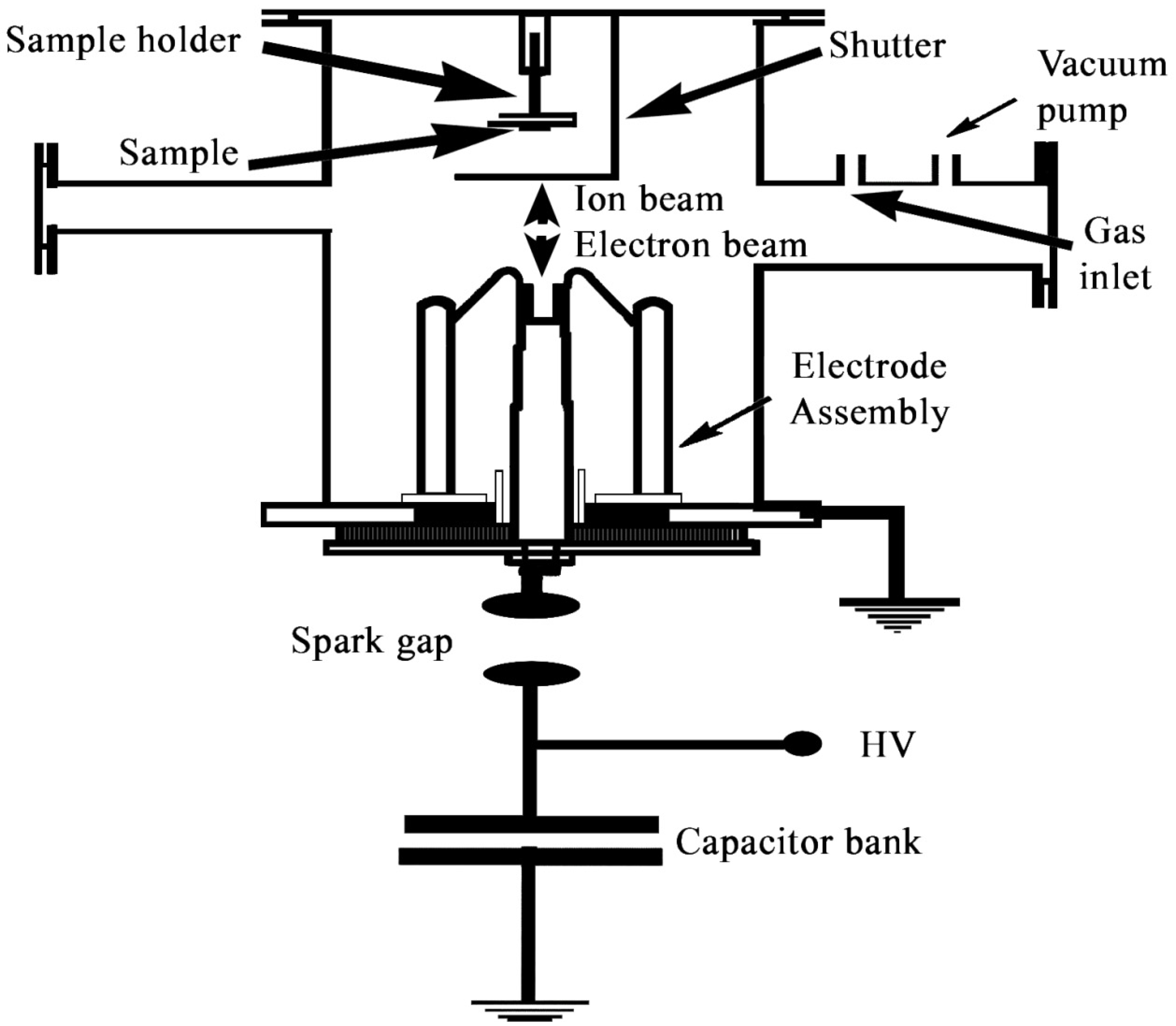
2.1. Experimental Setup

A Mather plasma focus (UNU/ICTP 1.5 kJ, Kuala Lumpur, Malaysia) was used for PTFE coating of Ti samples with a capacitor bank of 9 µF at a peak current of about 160 kA and charged at 18 kV. Figure 1 illustrates the schematic experimental setup which consists of six symmetric copper rods surrounding a central copper rod.
The central rod acts as an anode and six equidistant surrounding rods are used as a cathode. For enhancement of X-rays, ions and electrons emission from the focus region, the anode is slightly tampered.

2.2. Sample Preparation

The square type samples with 10 × 10 mm2 area and thickness of 2 mm are prepared by cutting a pure Ti sheet with a METKON FINOCUT cutter (Bursa, Turkey). A METKON GRIPCO2V polishing machine (Bursa, Turkey) is used for mirror finish mechanical polishing of samples. Samples are cleaned ultrasonically in acetone for 30 min. The samples are then held on a substrate holder, axially at a distance of 8 cm from the tip of the anode, behind a moveable aluminum shutter. This specimen distance ensures the prevention of sample damage by the high-energy ion beam. The aluminum shutter covers the sample so that the ion beam, emitted for the few conditioning shots, will not affect the samples.
When the final focus phase is achieved, the interaction of the current sheath and bombardment of high-energy electrons and ions on the surface of electrodes results in emission of vapors from the anode [23]. The anode tip is engraved up to 10 mm deep to reduce copper impurities. The PTFE material is placed in the anode. By using a rotary van pump, the chamber is evacuated up to 10−2 mbar, then the chamber is filled with high-purity argon gas. The impurities are minimized by purging out argon gas several times. Electrical breakdown occurs along the insulator sleeve due to the application of capacitor voltage across the electrodes immersed inside the low-pressure gas. High current builds up along the current sheath of the highly ionized plasma which is accelerated towards the tip by self-generated magnetic force J × B. The radial current sheath collapses when it reaches the tip of the anode. It generates a highly dense (1025–1026 m−3) transient plasma column, with electron temperature ranging from 1–2 KeV [24]. At this instant, magnetic hydrodynamic instabilities grow. As a result of instabilities, the electron temperature increases and an intense electric field develops. Due to the quick development of sausage instability at the necking of the column, plasma focus occurs, leading to its disruption. Instantly after disruption, beams of ions as well as electrons are emitted. The plasma column collapses due to enhanced electric field, coupled with magnetic field, and ions move away axially and electrons towards the tip of the anode. PTFE ionizes due to this stream of electrons. To monitor the focusing efficiency, a Rogowski coil and high-voltage probe are used. The intense voltage spike across the high-voltage probe and steep current along the Rogowski coil are the confirmation of strong focusing and ensure the transferring of efficient energy and heating of plasma focus. Impurities are extracted when the system is operated in gas flow mode. It is observed that for argon gas at 0.7 mbar pressure and 18 kV capacitor bank applied voltage, efficient focusing is obtained. Optimum filling pressure and charging voltage are maintained throughout the experiment, to ensure energetic ion flux for the exposure of the sample. A GaAs detector is used to measure ion energy on the surface of the substrate. The detector is placed at a distance of 8 cm from the anode tip with biasing voltage of 300 V. A four-channel Gould 4074A (Champaign, IL, USA) digital oscilloscope is used to record the ion beam signal. Several focus shots are carried out to obtain strong focusing on each loading of a new sample. Ions are emitted in several bunches for a single focus shot with a duration of a few nanoseconds from the pinched region. The substrate surface is etched, cleaned and heated by the ions emitted from the first bunch. A thin layer of PTFE at an elevated temperature is deposited on the substrate surface and thus the separate heating of samples is avoided. The consequent beam of ions is responsible for PTFE coating on Ti. The residual plasma impinges on the high-temperature Ti surface. The high temperature of the substrate surface helps the PTFE ions to diffuse deeply into the surface.

3. Results and Discussion

This section contains the results drawn on the basis of characterization of samples for structural, mechanical and surface properties. The detailed discussion and interpretation of the results are also given in this section.

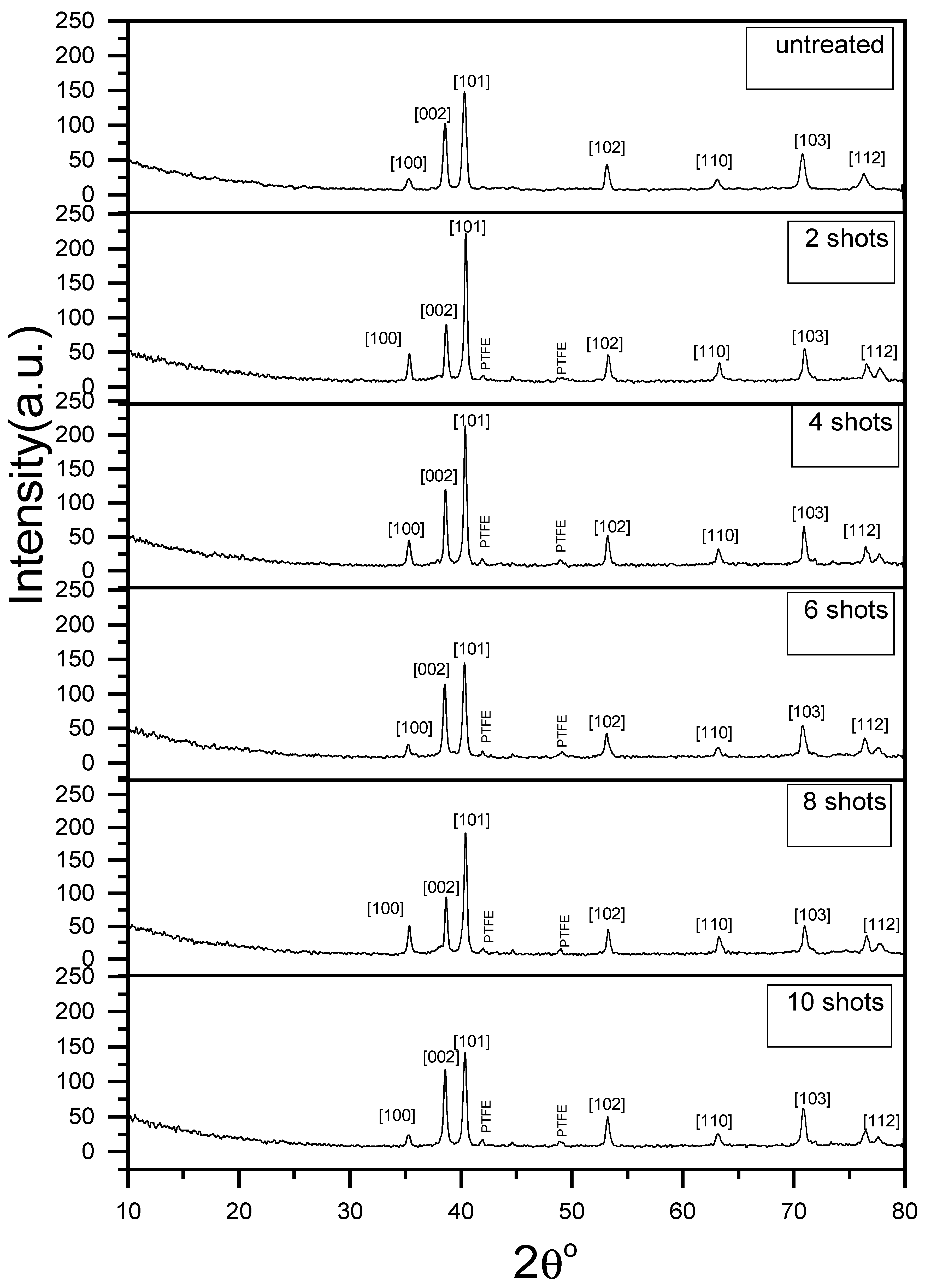
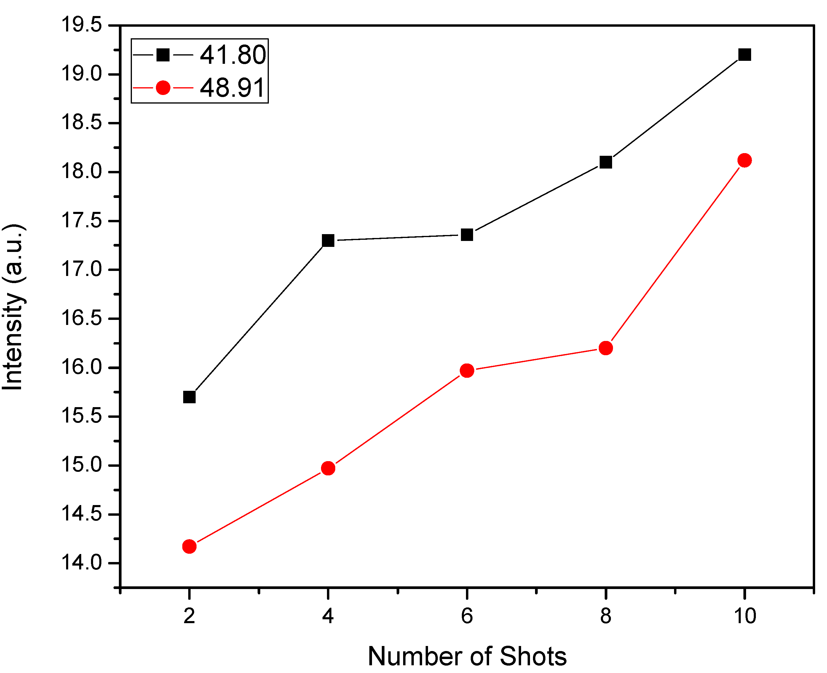
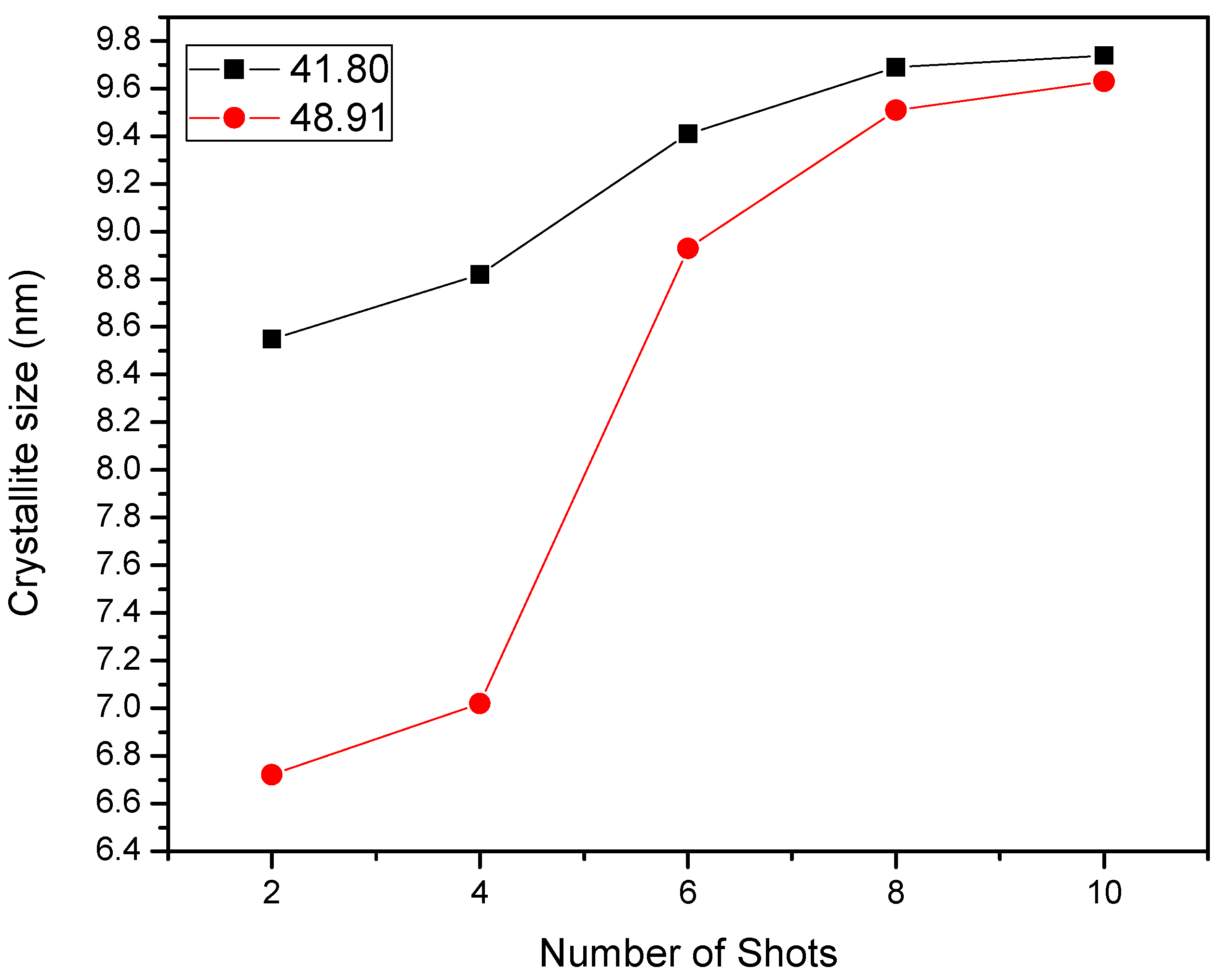
3.1. Structural Properties

The structural properties are characterized by a X-ray Diffractometer (PW3040/60 X’pert PRO, PANalytical, Malvern, UK). PTFE-treated samples, for different focus shots, are analyzed for structural change. The XRD spectra present clear peaks of PTFE in all the treated samples. X-ray diffraction analysis is performed using a flat camera and 40 kev Cu Kα (λ = 1.54 Å) radiation. The samples are scanned from 10° to 80° at 2θ. The XRD pattern of untreated and PTFE-treated samples, for different focus shots, is presented in Figure 2. The peaks corresponding to 2θ = 38.66°, 2θ = 40.44°, 2θ = 53.22°, 2θ = 63.25°, 2θ = 70.89°, 2θ = 76.61° and 2θ = 77.73° are presented in the spectra of untreated Ti samples [25,26].
The main peaks corresponding to PTFE are located at 2θ = 41.80° and 2θ = 48.90°. Peaks, due to titanium and PTFE, are observed at 2θ = 70.89° and 2θ = 76.61° simultaneously [27]. PTFE peaks for two shots are broader and do not resolve precisely. Initially, for a smaller number of shots, smaller PTFE clusters are induced in the Ti matrix. The results can be easily seen in the spectra of the samples exposed for 2, 4, 6, 8 and 10 focus shots. The relative intensity of the PTFE peak is the maximum for 10 shots, as shown in Figure 3.
PTFE precipitates grow with increasing dose of ions. As a result, the following focus shots achieve coalescence and, due to migration of PTFE atoms, clusters are formed in Ti. It is assumed that Ti is in a liquid phase when the secondary ion beam penetrates into deeper layers. The PTFE surface thickness is estimated to be about 299 nm by SRIM [28]. The Scherrer formula is used to calculate the area of the coherent X-ray scattering region [29].
Area   of   the   coherent   X ray   scattering   region   = K λ / FWHM cos θ
Here, K is the Scherrer constant (~0.99); λ = 0.15406 nm for Cu Kα; and FWHM is full width half maxima of the peak which is taken in radians. Applying this formula, the average area of the coherent X-ray scattering region of PTFE film is calculated as approximately 9 ± 1 nm, as shown in Figure 4.
The area of the coherent X-ray scattering region depends upon the temperature of the substrate and flux of ion energy. The PTFE peaks’ heights increase for a larger number of focus shots. Highly energetic PTFE ion radiation damages the Ti surface which is due to the stress component.

3.2. Tribological Behaviors

Tribological properties were characterized by a pin on disc test. The friction coefficient of PTFE is measured in air at room temperature by a pin on disc tribometer (CETR-UMT 2ASTM G99-95, Campbell, CA, USA), using an indexable 3 mm high-strength steel ball by the ASTM G99-95a method. The pin on disc wear test is performed by using 8500 pin cycles and fixed load of 6 N at an angular velocity of 3 cm·s−1 for 30 min. Friction coefficients for untreated and treated eight-shot samples are 0.564 and 0.369, respectively, indicating that the coefficient of friction reduces by 35%. Additionally, the wear rate for untreated and treated eight-shot samples is 0.00029 g/min and 0.00003 g/min, respectively, indicating that wear rate decreases by 89%. Recent studies have shown that a decrease in the friction is linked with surface hardening [30,31]. Recently, Wang et al. fabricated a lubricant composite coating on the surface of Ti6Al4V alloy by micro-arc oxidation as well as grafting hydrophilic polymer [32]. The results showed that the composite coating revealed the low friction coefficient and promising wear resistance in water under a low contact stress of 1.52 MPa. This represents considerable wear resistance enhancement and adhesion strength of PTFE with Ti.

3.3. Surface Properties

Surface properties were characterized by a scanning electron microscope (SEM, JEOL, JASM-6490A, Tokyo, Japan) and energy dispersive X-ray (EDX) analysis.

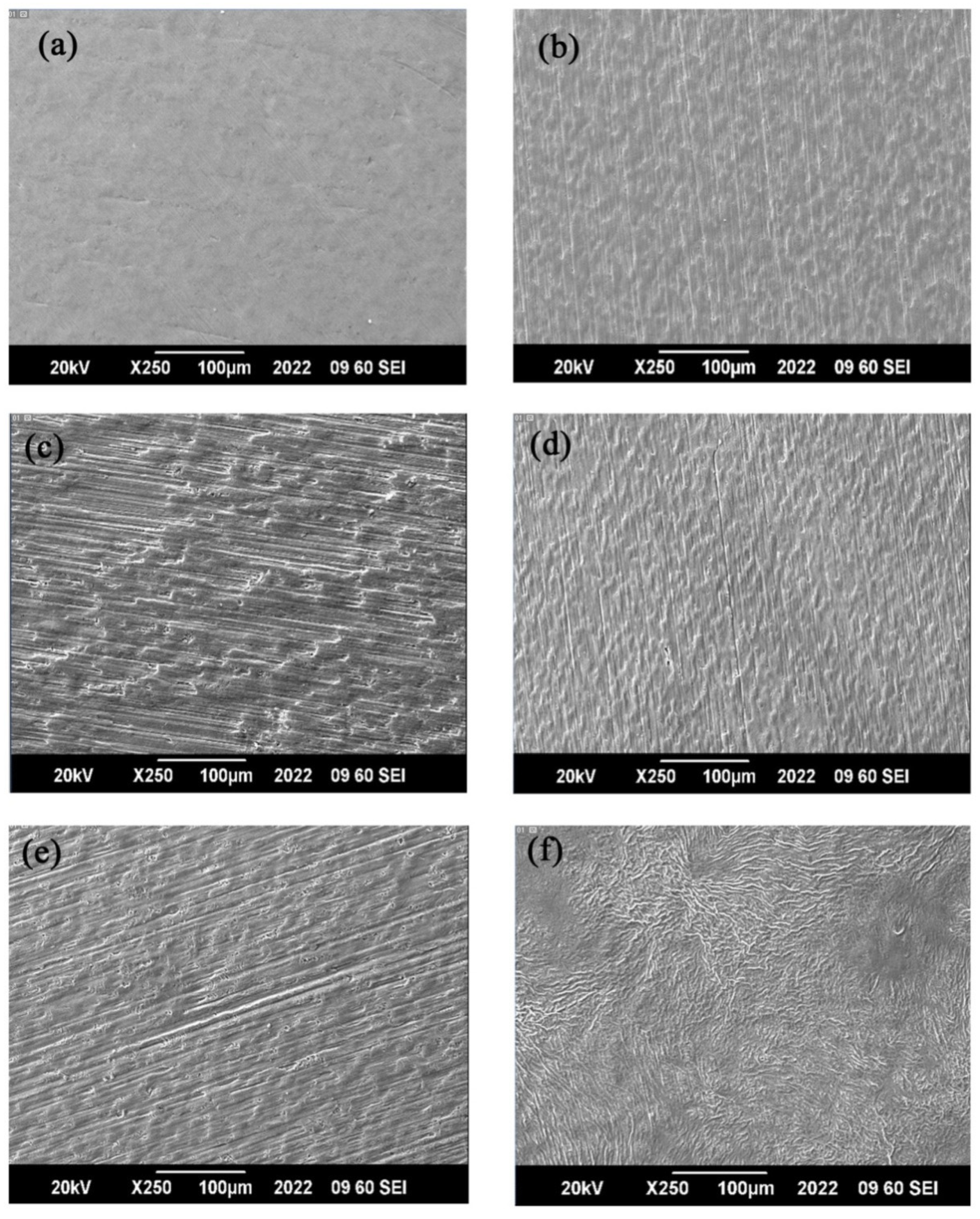
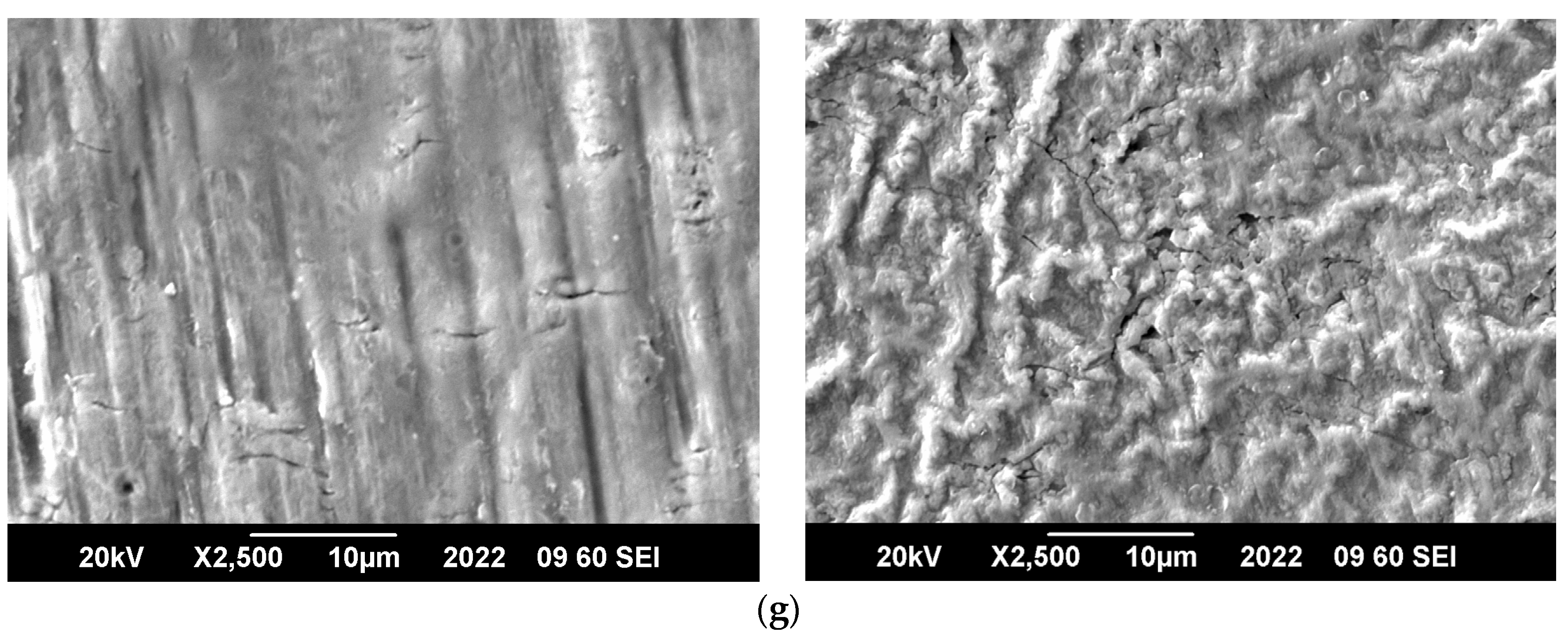
3.3.1. Scanning Electron Microscope (SEM)

SEM micrographs of untreated and treated samples exhibit the surface morphology. On examination, a clear difference in the surface appearance of untreated Ti and PTFE-treated Ti is observed. The surface of untreated samples is shiny and a silvery gray color, as shown in Figure 5a. The PTFE-treated samples have a white–gray appearance, as illustrated in Figure 5b–f. PTFE has vibrant viscosity in an ionic state and PTFE ions filled as well as covered most of the polishing surface of Ti [33,34,35]. The micrographs of the PTFE-coated sample surface presents a smooth layer of smaller grain. The ion bombardment results in restructuring of the surface of Ti due to cascaded collisions. The reaction of Ti ablated or sputtered with gas phase PTFE ions results in the deposition of PTFE on the Ti substrate as a layer.
The micrographs at 2500× and 250× magnifications confirm PTFE deposition due to bombardment of ions. At 250× magnification, as shown in Figure 5f, the PTFE layer is uniform over the surface of the substrate whereas, at magnification of 2500×, point-like structures of clusters/flakes of different sizes are shown in Figure 5g. With the increase in focus shots, the cluster size is increased. When thin film growth is associated with ions of low energy, then the area of the coherent X-ray scattering region usually decreases.
The ion bombardment decreases the area of the coherent X-ray scattering region, assisted by nucleation rate enhancement at the time of film growth. In some specific cases, the area of the coherent X-ray scattering region increases by the ion bombardment. In such situations, crystal growth might be favored by high strain energy and increase in adatom mobility, caused by high local temperature. During ion bombardment in thin film deposition, the area of the coherent X-ray scattering region depends upon energy of the ion beam. Ions, with energy less than 10 kev, usually favor a small area of the coherent X-ray scattering region whereas beam energies, in the range of a few tens of kev, enhance this scattering region. High-energy ions penetrate deeper and affect recrystallization and motion of the grain boundary in buried regions where an increase in the area of the coherent X-ray scattering region may occur. The clusters/flakes of different size are associated with wide energy spectra of the ion beam (25 kev to 8 Mev) emitted from DPF. Figure 5a–g demonstrate the surface profile of Ti and PTFE film deposition by operating a UNU/ICTP device at an axial position of 8 cm. The film surface has uniform thickness, non-porous cracks and free granular morphology. With excessive energy deposition on the substrate, the damaged surface is more significant. Microscopic damage is caused by the transient temperature rise of the substrate surface. The thickness of the modified layer is not uniform along the grain boundaries and in Ti grains. The sample treated for 8 focus shots shows a smooth surface with closely arranged grains and this is due to appropriate ion energy flux for the grain growth. The rougher surface of samples treated with 10 focus shots with micro-cracks is illustrated in Figure 5g, which is because of high dose of PTFE ions results in inflammation of the substrate surface, increasing its roughness as in the case of nitriding of Ti [36,37,38]. It is considered that high-energy ion flux, as for 10 shots, produced during steady and robust focusing action, carries too much energy flux to the substrate, causing sputtering as well as etching which causes the damage along with roughness of the surface. Due to highly energetic ions, the partial melting and quick re-solidification after cooling down are another reason for the surface roughness. The creation of micro-cracks may also be a result of thermal shock, taking place due to the incident ion beam’s fast heating and strong temperature gradients. It is concluded that PTFE crystallites form and grow as a function of ion dose and ion energy up to 8 focus shots, which are appropriate for surface smoothness. This is in good agreement with the XRD results. We may say that micro-structural changes depend upon the ion dose and energy delivered to the sample surface by the plasma focus system.

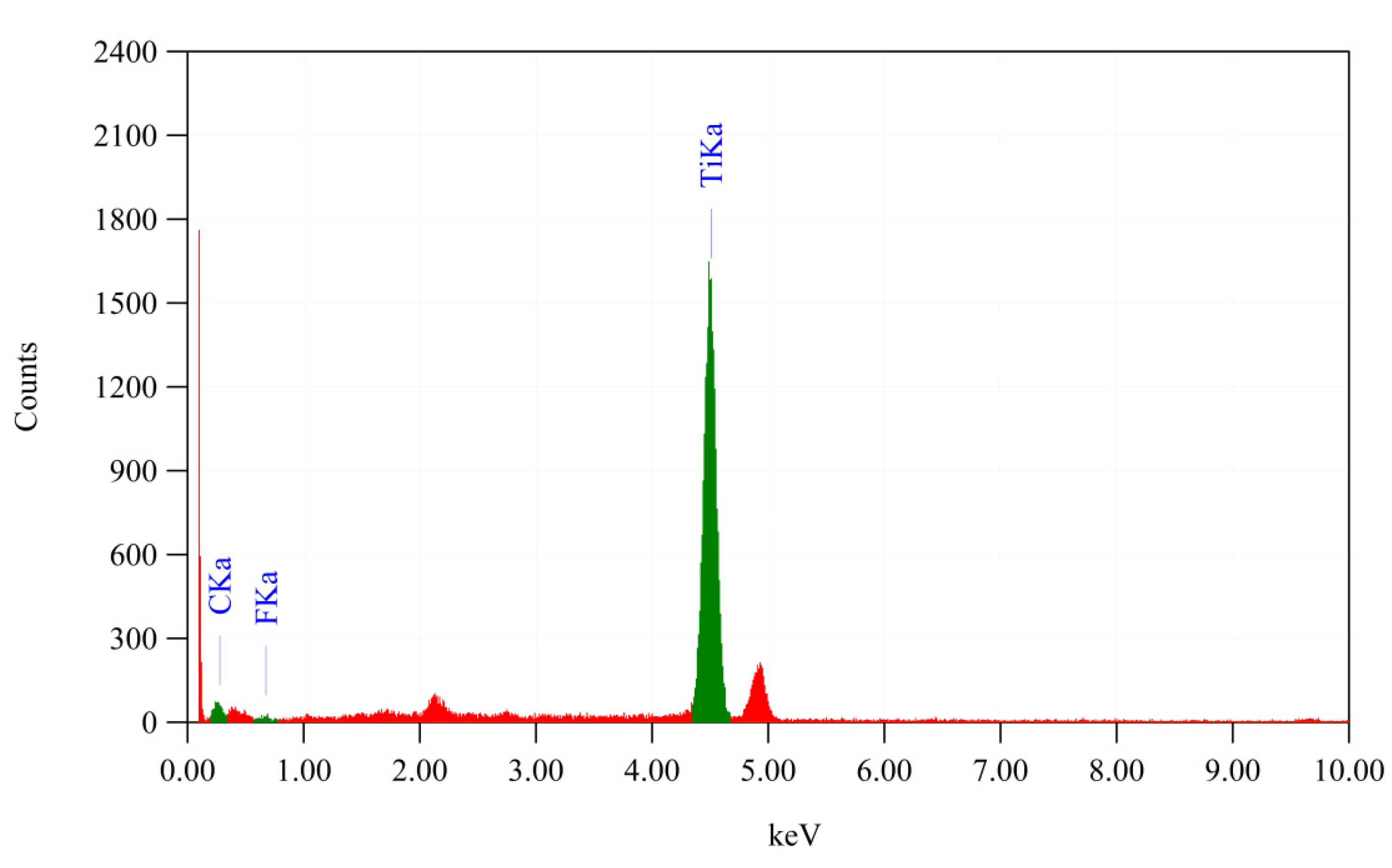
3.3.2. Energy Dispersive X-ray (EDX) Analysis

The elemental composition of samples is estimated by EDX (40 keV). All the treated samples give similar spectra but with variation in relative intensities of peaks, showing carbon, fluorine and Ti concentrations in the samples with an increasing number of focus shots. The peak intensity is minimum at two shots and maximum at 10 shots. Figure 6 illustrates a typical EDX image along with film elemental maps at 8 cm by a UNU/ICTP device for 10 shots. The EDX maps of the film imaging filters are used to show the spatial distribution of elements in the coating. The film is found to be homogeneous regarding the elemental distribution of fluorine and carbon. The variation in Ti concentration in the ion-treated samples is attributed to the increase in carbon and fluorine concentration. Table 1 presents the EDX data of Ti, C and F concentration (at.%). The maximum C and F distributions are found to be 14.16 at.% and 7.21 at.% in the film surface deposited for 10 shots.
In PTFE coatings, the levels of C, F and Ti were found to be in the range of 3.25%–14.16%, 2.63%–7.21% and 94.12%–78.63%, respectively. The reduced level of at.% of Ti detected in these samples, compared to the untreated Ti substrate, is indicative of a high degree of coating of PTFE for all Ti samples.

4. Conclusions and Future Prospects

  • This study established that PTFE coating on Ti by plasma focus enhances wear resistance when compared to untreated Ti.
  • The friction coefficient reduces up to 35% and wear rate decreases by 89% as shown by a pin on disc test.
  • The morphology of the film surface shows smoothening of Ti substrate by PTFE content scattered consistently on the Ti surface.
  • The XRD analysis is consistent with the composition analysis by EDX.
  • It is concluded that PTFE crystallites grow as a function of ion dose.
  • The quantitative EDX analysis specifies that the carbon and fluorine content in the PTFE-coated layer is mainly dependent on ion energy flux.
  • This plasma ion coating would be very appropriate for studies aiming to use and tailor this new coating material for applications in future sensitive rotatory devices.

Author Contributions

Data curation, S.K.; Formal analysis, S.K.; Methodology, E.M.T.-E., A.M. and M.A.; Supervision, A.M.; Validation, E.M.T.-E.; Visualization, M.A.; Writing – original draft, S.K.; Writing – review and editing, E.M.T.-E., A.M. and M.A. All authors have read and agreed to the published version of the manuscript.

Funding

This research is supported by ASPIRE, the technology program management pillar of Abu Dhabi’s Advanced Technology Research Council (ATRC), via the ASPIRE Award for Research Excellence initiative.

Institutional Review Board Statement

Not applicable.

Informed Consent Statement

Not applicable.

Data Availability Statement

Data sharing is not applicable.

Conflicts of Interest

The authors declare no conflict of interest.

References

  1. Ao, N.; Liu, D.; Wang, S.; Zhao, Q.; Zhang, X.; Zhang, M. Microstructure and tribological behavior of a TiO2/hBN composite ceramic coating formed via micro-arc oxidation of Ti–6Al–4V alloy. J. Mater. Sci. Technol. 2016, 32, 1071–1076. [Google Scholar] [CrossRef]
  2. Lu, X.; Mohedano, M.; Blawert, C.; Matykina, E.; Arrabal, R.; Kainer, K.U.; Zheludkevich, M.L. Plasma electrolytic oxidation coatings with particle additions—A review. Surf. Coat. Technol. 2016, 307, 1165–1182. [Google Scholar] [CrossRef]
  3. Zhang, Y.; Li, C.; Jia, D.; Zhang, D.; Zhang, X. Experimental evaluation of the lubrication performance of MoS2/CNT nanofluid for minimal quantity lubrication in Ni-based alloy grinding. Int. J. Mach. Tools Manuf. 2015, 99, 19–33. [Google Scholar] [CrossRef]
  4. Zhang, R.; Zhao, J.; Liang, J. A novel multifunctional PTFE/PEO composite coating prepared by one-step method. Surf. Coat. Technol. 2016, 299, 90–95. [Google Scholar] [CrossRef]
  5. Bodas, D.S.; Gangal, S.A.; Micromech, J. RF Sputtered Polytetrafluoroethylene—A Potential Masking Material for MEMS Fabrication Process. J. Micromech. Microeng. 2005, 15, 1102. Available online: https://ui.adsabs.harvard.edu/link_gateway/2005JMiMi.15.1102B/doi:10.1088/0960-1317/15/5/029 (accessed on 18 August 2022). [CrossRef]
  6. Andersson, J.; Erck, R.A.; Erdemir, A. Friction of diamond-like carbon films in different atmospheres. Wear 2003, 254, 1070. [Google Scholar] [CrossRef]
  7. Diamanti, M.A.; Sebastiani, M.; Mangione, V.; Del, B.C.; Pedeferri, M.P.; Bemporad, E.; Cigada, A.; Carassiti, F. Multi-step anodizing on Ti6Al4V components to improve tribomechanical performances. Surf. Coat. Technol. 2013, 227, 19–27. [Google Scholar] [CrossRef]
  8. Meng, F.; Li, Z.; Liu, X. Synthesis of tantalum thin films on titanium by plasma immersion ion implantation and deposition. Surf. Coat. Technol. 2013, 229, 205–209. [Google Scholar] [CrossRef]
  9. Yuan, X.; Tan, F.; Xu, H.; Zhang, S.; Qu, F.; Liu, J. Effects of different electrolytes for micro-arc oxidation on the bond strength between titanium and porcelain. J. Prosthodont. Res. 2017, 61, 297–304. [Google Scholar] [CrossRef]
  10. Aliofkhazraei, M.; Sabour, R.A.; Shahrabi, T. Abrasive wear behavior of Si3N4/TiO2 nanocomposite coatings fabricated by plasma electrolytic oxidation. Surf. Coat. Technol. 2010, 205, S41–S46. [Google Scholar] [CrossRef]
  11. Ramazanova, J.M.; Zamalitdinova, M.G. Physical and mechanical properties investigation of oxide coatings on titanium. Complex Use Miner. Resour. 2019, 2, 34–41. [Google Scholar] [CrossRef]
  12. Zhu, Y.; Wang, W.; Jia, X.; Akasaka, T.; Liao, S.; Watari, F. Deposition of TiC film on titanium for abrasion resistant implant material by ion-enhanced triode plasma CVD. Appl. Surf. Sci. 2012, 262, 156–158. [Google Scholar] [CrossRef]
  13. Marin, E.; Offoiach, R.; Regis, M.; Fusi, S.; Lanzutti, A.; Fedrizzi, L. Diffusive thermal treatments combined with PVD coatings for tribological protection of titanium alloys. Mater. Des. 2016, 89, 314–322. [Google Scholar] [CrossRef]
  14. Jin, G.; Cao, H.; Qiao, Y.; Meng, F.; Zhu, H.; Liu, X. Osteogenic activity and antibacterial effect of zinc ion implanted titanium. Colloids Surf. B Biointerfaces 2014, 117, 158–165. [Google Scholar] [CrossRef]
  15. Yang, X.; Jiang, Z.P.; Ding, X.F.; Hao, G.J.; Liang, Y.F.; Lin, J.P. Influence of solvent and electrical voltage on cathode plasma electrolytic deposition of Al2O3 antioxidation coatings on Ti-45Al-8.5Nb alloy. Metals 2018, 8, 308. [Google Scholar] [CrossRef]
  16. Daram, P.; Banjongprasert, C.; Thongsuwan, W.; Jiansirisomboon, S. Microstructure and photocatalytic activities of thermal sprayed titanium dioxide/carbon nanotubes composite coatings. Surf. Coat. Technol. 2016, 306, 290–294. [Google Scholar] [CrossRef]
  17. Razmi, A.; Yesildal, R. Microstructure and mechanical properties of TiN/TiCN/TiC multilayer thin films deposited by magnetron sputtering. Int. J. Innov. Res. Rev. 2021, 5, 15–20. Available online: http://www.injirr.com/article/view/67 (accessed on 18 August 2022).
  18. Tillmann, W.; Grisales, D.; Tovar, C.M.; Contreras, E.; Apel, D.; Nienhaus, A.; Stangier, D.; Lopes, N.F. Tribologicalbehaviour of low carbon-containing TiAlCN coatings deposited by hybrid (DCMS/HiPIMS) technique. Tribol. Int. 2020, 151, 106528. [Google Scholar] [CrossRef]
  19. Sadiq, M.; Ahmad, S.; Shafiq, M.; Zakaullah, M. Plasma Processes and Polymers. In Enhanced Crystallinity od PTFE by Ion Irradiation in a Dense Plasma Focus; Wiley: Hoboken, NJ, USA, 2007; Volume 4, p. 186. [Google Scholar] [CrossRef]
  20. Podgornik, B.; Borovsak, U.; Megusar, F.; Kosir, K. Performance of low-friction coatings in helium environments. Surf. Coat. Technol. 2012, 206, 4651. [Google Scholar] [CrossRef]
  21. Chen, Z.X.; Ren, X.P.; Ren, L.M.; Wang, T.C.; Qi, X.W.; Yang, Y.L. Improving the tribological properties of spark-anodized titanium by magnetron sputtered diamond-like carbon. Coatings 2018, 8, 83. [Google Scholar] [CrossRef] [Green Version]
  22. Lianga, H.; Shia, B.; Fairchilda, A.; Caleb, T. Applications of plasma coatings in artificial joints. Vacuum 2004, 73, 317. [Google Scholar] [CrossRef]
  23. Murtaza, G.; Hussain, S.S.; Rehman, N.U.; Naseer, S.; Shafiq, M.; Zakaullah, M. Carburizing of zirconium using a low energy Mather type plasma focus. Surf. Coat. Technol. 2011, 205, 3012–3019. [Google Scholar] [CrossRef]
  24. Zeb, S.; Murtza, G.; Zakaullah, M. Influence of the filling gas on plasma focus assisted diamondlike carbon coating at room temperature. J. Appl. Phys. 2007, 101, 063307. [Google Scholar] [CrossRef]
  25. Shafiq, M.; Hassan, M.; Shazad, K.; Qayyum, A.; Ahmad, S.; Rawat, R.S.; Zakaullaha, M. Pulsed ion beam-assisted carburizing of titanium in methane discharge. Chin. Phys. B 2010, 19, 012801. [Google Scholar] [CrossRef]
  26. Pattanayak, D.K.; Mathur, V.; Rao, B.T.; Rama, T.R. Synthesis and characterization of Titanium-Calcium orthophosphate Composites for Bio Applications. Trends Biomater. Artif. Organs. 2003, 17, 8. Available online: link.gale.com/apps/doc/A165363941/HRCA?u=anon~a65ce6be&sid=googleScholar&xid=f76d2bc2 (accessed on 18 August 2022).
  27. Smolyanskii, A.S.; Politova, E.D.; Koshkina, O.A.; Arsentyev, M.A.; Kusch, P.P.; Moskvitin, L.V.; Slesarenko, S.V.; Kiryukhin, D.P.; Trakhtenberg, L.L. Structure of Polytetrafluoroethylene Modified by the Combined Action of γ-Radiation and High Temperatures. Polymers 2021, 13, 3678. [Google Scholar] [CrossRef]
  28. Yuzhou, W.; Janne, P.; Lingfeng, H.; Tiankai, Y.; David, E.A.A.H. Combining mesoscale thermal transport and x-ray diffraction measurements to characterize early-stage evolution of irradiation-induced defects in ceramics. Acta Mater. 2020, 193, 61–70. [Google Scholar] [CrossRef]
  29. Rabanal, M.E.; Varez, A.; Levenfeld, B.; Torralba, J.M. Magnetic Properties of Mg-Ferrite after Milling Process. J. Mater. Process Technol. 2003, 143, 470. [Google Scholar] [CrossRef]
  30. Rakhadilov, B.; Buitkenov, D.; Sagdoldina, Z.; Seitov, B.; Kurbanbekov, S.; Adilkanova, M. Structural Features and Tribological Properties of Detonation Gun Sprayed Ti–Si–C Coating. Coatings 2021, 11, 141. [Google Scholar] [CrossRef]
  31. Rakhadilov, B.; Buitkenov, D.; Idrisheva, Z.; Zhamanbayeva, M.; Pazylbek, S.; Baizhan, D. Effect of Pulsed-Plasma Treatment on the Structural-Phase Composition and Tribological Properties of Detonation Coatings Based on Ti–Si–C. Coatings 2021, 11, 795. [Google Scholar] [CrossRef]
  32. Wang, K.; Xiong, D. Construction of lubricant composite coating on Ti6Al4V alloy using micro-arc oxidation and grafting hydrophilic polymer. Mater. Sci. Eng. C 2018, 90, 219–226. [Google Scholar] [CrossRef] [PubMed]
  33. Gamboni, O.C.; Riul, C.; Billardon, R.; Bose, W.W.; Schmitt, N.; Canto, R.B. On the formation of defects induced by air trapping during cold pressing of PTFE powder. Polymer 2016, 82, 75–86. [Google Scholar] [CrossRef]
  34. Bai, D.Y.; Bai, H.W.; Fu, Q. Recent progress on sintering molding of polymers. Polym. Bull. 2017, 10, 13–22. [Google Scholar] [CrossRef]
  35. Huang, Q.L.; Xiao, C.F.; Hu, X.Y.; Bian, L.N. Preparation and properties of poly (Tetrafluoroethylene) membrane. Polym. Mater. Sci. Eng. 2010, 26, 123–126. [Google Scholar]
  36. Alves, C., Jr.; Neto, C.L.B.G.; Morais, G.H.; Silva, C.F.; Hajek, V. Nitriding of titanium disks and industrial dental implants using hollow cathode discharge. Surf. Coat. Technol. 2005, 194, 196–202. [Google Scholar] [CrossRef]
  37. Morgiel, J.; Szymkiewicz, K.; Pomorska, M.; Ozga, P.; Toboła, D.; Tarnowski, M.; Wierzchoń, T. Surface roughening of Ti-6Al-7Nb alloy plasma nitrided at cathode potential. Appl. Surf. Sci. 2022, 574, 151639. [Google Scholar] [CrossRef]
  38. Kamat, A.M.; Copley, S.M.; Segall, A.E.; Todd, J.A. Laser-sustained plasma (LSP) nitriding of titanium: A review. Coatings 2019, 9, 283. [Google Scholar] [CrossRef] [Green Version]
Figure 1. Schematic arrangement of Mather type plasma focus used for ion plasma coating of samples. Reprinted from reference [23] with permission from Elsevier.
Coatings 12 01300 g001
Figure 2. XRD pattern of untreated and PTFE-coated Ti samples.
Coatings 12 01300 g002
Figure 3. Variation in intensity recorded for PTFE-coated Ti samples as a function of number of shots.
Coatings 12 01300 g003
Figure 4. Variation in crystallite size for PTFE-coated Ti samples as a function of number of shots.
Coatings 12 01300 g004
Figure 5. SEM micrograph of samples in the form of (a) untreated, (b) 2 shots, (c) 4 shots, (d) 6 shots, (e) 8 shots and (f) 10 shots. (g) Comparison of samples with 8 shots (left) and 10 shots (right) at magnification of 2500×.
Coatings 12 01300 g005aCoatings 12 01300 g005b
Figure 6. Quantitative analysis of the treated samples measured using EDX.
Coatings 12 01300 g006
Table 1. EDX elemental composition of the samples.
ShotsF
(X)
S = X x ¯ 2 n 1 C
(Y)
S = Y y ¯ 2 n 1 Ti
(Z)
S = Z z ¯ 2 n 1
22.631.7503.256.57494.1215.10
43.410.8703.495.97393.1011.404
66.080.1619.320.22184.600.762
87.050.78611.672.70981.281.604
107.210.93514.168.35778.6314.884
Publisher’s Note: MDPI stays neutral with regard to jurisdictional claims in published maps and institutional affiliations.

