1. Introduction
Optical bistability at the nanoscale is an attractive research field due to the interesting phenomena it encompasses resulting from controlling light with light [
1], and its promising potential applications, including optical memories [
2,
3,
4], optical transistors [
5] and all-optical switches [
6,
7]. Specifically, optical bistability is a nonlinear optical effect arising from third-order nonlinear susceptibility in which the refractive index depends on the light intensity exhibiting self-Kerr nonlinearity [
8]. A system is said to be bistable if it has two output states corresponding to the same value of input intensity. This requires an internal feedback mechanism provided by a Kerr nonlinear medium situated inside an optical cavity that enhances the light–matter interaction [
7,
9].
However, increasing the number of stable output states against a specific input optical state, i.e., optical multistability, can be more attractive than binary optical stability for many applications, such as all-optical switching [
10,
11,
12], quantum computing and quantum information processing [
13]. Thus, the optical multistability has been extensively studied in multi-level atomic systems with different configurations inside an optical cavity via the interactions between the nonlinear medium and two optical fields [
12,
14,
15,
16].
As a promising controllable platform for the nonlinear applications, hybrid plasmonic systems represent good candidates to demonstrate optical multistability [
17,
18,
19,
20,
21]. To be of practical interest, the threshold value of input power for multistability should be small [
9]. Thanks to the enhanced optical intensities in plasmonic nanocomposites, the desired threshold power required to obtain nonlinear effects is relatively small [
20,
22]. Moreover, multi-level atomic systems, under coherent excitation resulting in electromagnetically induced transparency (EIT), exhibit an enhanced third-order nonlinear response that could be employed for optical bistability and multistability [
20,
23,
24,
25]. For metal nanoparticle (MNP)–quantum dot (QD) hybrid systems, it has been shown that enhanced optical bistability can be controlled by the center-to-center distances between MNP and QD [
22,
26].
On the other hand, due to the unique nonlinear optical properties resulting from the linear dispersion relation near Dirac points, graphene has remarkably large third-order nonlinear optical susceptibility [
27,
28]. Recently, Dai X. et al. proposed a modified Kretchmann–Reather configuration to realize low threshold optical bistable devices at terahertz frequencies by using a plasmonic structure with an insertion of graphene [
29]. Moreover, it has been experimentally shown that surface plasmons of graphene can be used as an internal feedback to demonstrate an ultralow threshold optical bistability due to the large nonlinear response exhibited by plasmonic structures [
30]. It has also been shown that controllable switching between optical bistability and optical multistability is feasible via frequency detunings of probe and control fields in a graphene monolayer system driven by an elliptically polarized control field and a right-hand circularly polarized probe field [
31]. Additionally, the optical bistability has been investigated in graphene multilayer systems. It was found that increasing the sheet numbers could lead to large bistability loop width [
32]. Recently, T. Naseri et. al. have theoretically investigated THz optical bistability of graphene-coated, cylindrical, core-shell gold nanoparticles. Their hybrid system has exhibited switching between optical bistability and multistability that can be achieved by controlling the Fermi energy and relaxation time of graphene [
33].
Interestingly, it has been theoretically shown that metal nanoparticle–graphene nanodisk– quantum dot hybrid systems can demonstrate a controllable giant self-Kerr nonlinearity under EIT conditions with low light intensity [
20]. Specifically, it has been found that the magnitude and sign of the nonlinear refractive index can be controlled by the geometry of the hybrid system, Rabi frequency of the control field and detuning of both probe and control fields. Thus, with this novel hybrid plasmonic system, it is expected to obtain low threshold optical bistability and multistability.
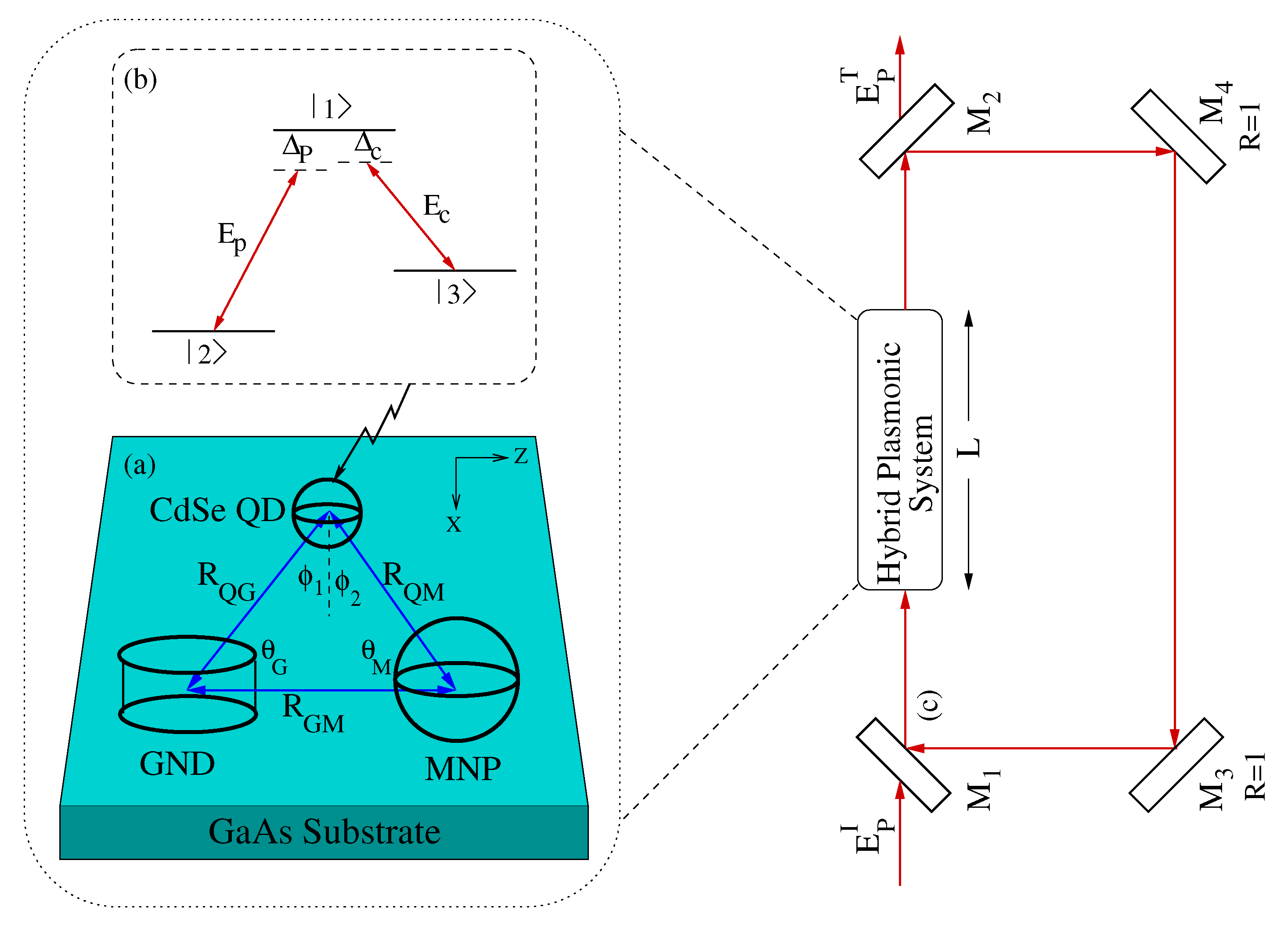
In this work, we investigated the optical multistability in the metal nanoparticle–graphene nanodisk–quantum dot (MNP–GND–QD) hybrid system depicted in
Figure 1, in a unidirectional ring cavity under EIT conditions where the quantum dot is modeled as a three level atomic system of Lambda configuration interacting with probe and control fields under the rotating wave approximation. The ranges of the system parameters were explored to optimize the optical multistability in such a novel system.
2. Theoretical Model
We consider the MNP–GND–QD hybrid system deposited on a gallium arsenide (GaAs) substrate as illustrated in
Figure 1 The QD is modeled as a three level atomic system of
configuration, where the transition
of dipole moment
is induced by the probe field of frequency
, Rabi frequency
and detuning of
, whereas the control field of frequency
, Rabi frequency
and detuning of
is driving the transition
of dipole moment
. Note that the dipole moment
(
) lies along the x (z) direction, so that the probe (control) field is applied along the x (z) direction. By analyzing the dipole–dipole interaction between the components of the system within the near field approximation, and solving the Lindblad quantum master equation using a Hamiltonian given in terms of the dipole field felt by the QD with two-photon detuning,
, in the rotating wave approximation, one can get the following equations of motion for the density matrix elements [
34]:
In Equations (1),
represents the spontaneous decay rate of the QD while
stands for the lower states’ dephasing. It is remarkable that the Rabi frequency of probe field (control field) is enhanced by a factor
(
), whereas
(
) enhances the dephasing rate induced by the probe (control) field. The enhancement factors
,
and
resulting from the dipole–dipole interaction are given for the system shown in
Figure 1 by [
34]:
(
) is the shape-dependent polarizability of GND induced by x (z) polarized field while
represents the polarizability of MNP given in terms of its volume and dielectric constant of the metal
and the background
[
35]. The center-to-center distances
,
and
are governed by the triangle law:
The MNP–GND–QD hybrid system sample of length
L is placed in a unidirectional ring cavity, having four mirrors as shown in
Figure 1. Mirrors
and
have identical reflection
R and transmission
T coefficients, where
. On the other hand, mirrors
and
are considered to be perfect reflectors to simplify optical multistability analysis. The MNP–GND–QD hybrid sample is situated in one of the arms of the cavity whose dynamics is described by the time evolution of the density matrix elements given by Equation (1). By using this standard model [
36], the probe field passes through the nonlinear medium of length
L from the partially transparent mirror
and is redirected back to the entry point by the system of mirrors illustrated in
Figure 1. Therefore, the optical stability can be analyzed by measuring the input and output beams generated by the two partially transmitting mirrors,
and
. Note that only the probe field acts as a cavity field and circulates inside the cavity, whereas the control field does not circulate inside the cavity. Therefore, the induced atomic polarization responsible for the optical multistability is
, where
N is the atomic number density,
is the transition dipole matrix element for the probe field transition that induces atomic coherence
. The propagation of the probe field
in the unidirectional optical ring cavity is governed by the following Maxwell equation under the slowly varying envelope approximation where
can be neglected [
8]:
By inserting the relation of polarization induced by the probe field into Equation (
4) we obtain at steady state:
For a perfectly tuned ring cavity, the incident (
) and the transmitted (
) probe fields obey the following boundary conditions in the steady state limit [
1]:
Solving the differential equation Equation (
5) using the boundary conditions given by Equation (6) leads to:
where
and
are normalized incident and output fields respectively given in a dimensionless form. Note that the second term of Equation (
7) describes the feedback mechanism provided by the system of mirrors that is essential to obtain optical bistability and multistability, where
C is the cooperation parameter that is proportional to the density of absorbing atoms in the cavity. More precisely,
, where
is the absorption coefficient.
3. Results and Discussion
In order to analyze the optical multistability in the MNP–GND–QD hybrid system and optimize its threshold in this system, we used the same parameters as in reference [
20], wherein it was shown that the MNP–GND–QD hybrid system can demonstrate giant self-Kerr nonlinearity under EIT conditions. Due to the unique properties of GND plasmons, including the high mobility and relatively long propagation distances [
37], we adjusted the energy of its plasmons to be resonant with the exciton of the QD. Consider GND of radius 7 nm and thickness of
nm at Fermi energy
eV and temperature 300 K, and carrier mobility
cm
2/Vs. With these parameters of GND deposited on GaAs substrate, we get plasmon resonances along x and z directions, i.e.,
eV and
eV. To support the plasmons of GND and provide more options to control the system, we used a spherical silver nanoparticle of
[
38], and plasma frequency of
s
−1, and damping rate of plasmons of
s
−1. CdSe self-assembled QD of
m
−3 was chosen to compensate for the losses of plasmons due to its optical emission band, which was near resonant with
eV in GND induced by x-polarized probe field. The physical parameters used in the numerical simulation are summarized in
Table 1.
In the following we investigate the controlling of optical multistability by the parameters of the system, including the inclination angle of the MNP; the edge-to-edge distances between GND and MNP; and the size of MNP. The effects of the detunings of the probe and control fields were examined in addition to the carrier mobility in GND. We compared the results under EIT conditions, i.e., , and , to when these conditions were not fulfilled in order to optimize the threshold of optical multistability in the proposed MNP–GND–QD hybrid system.
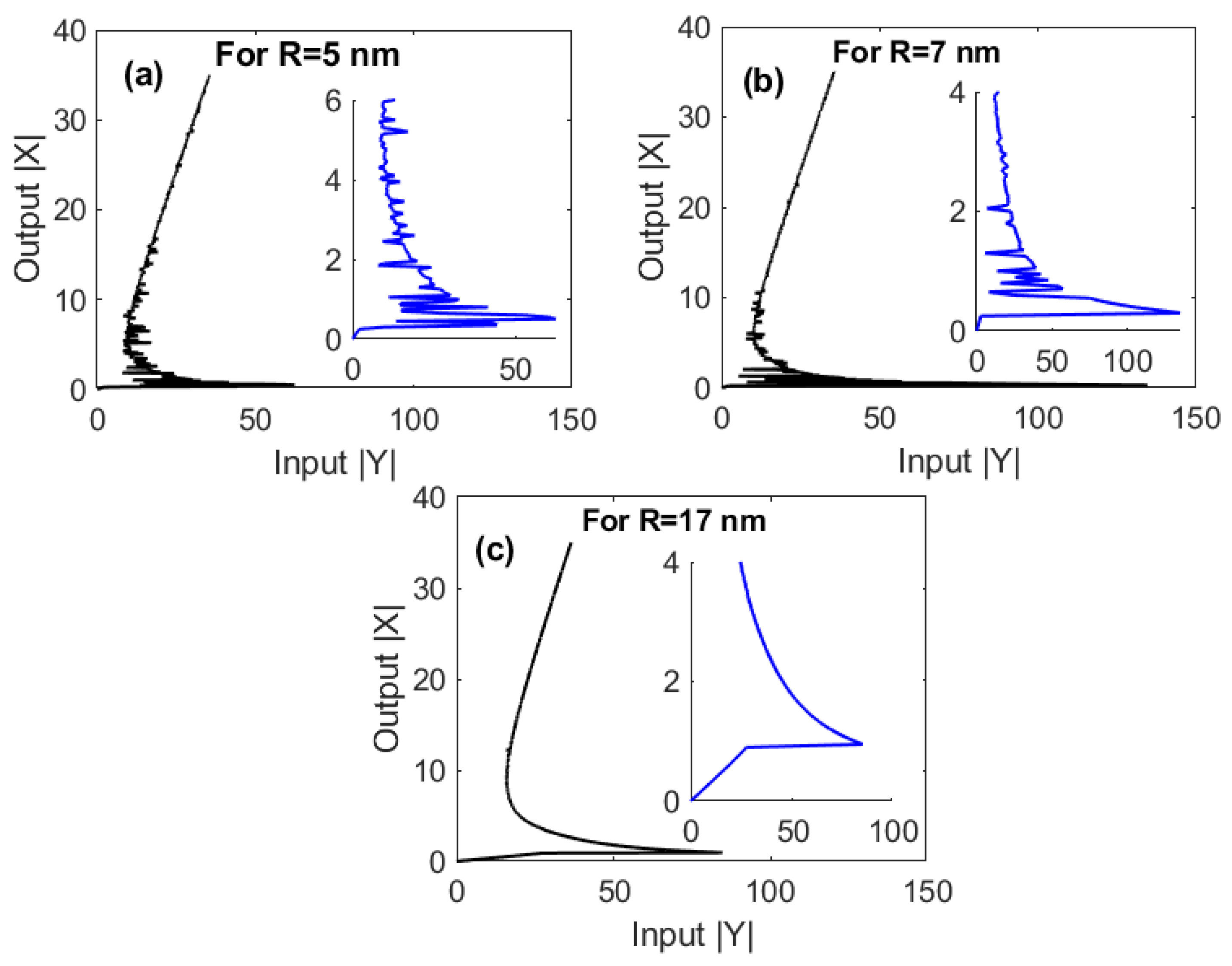
Under EIT conditions, i.e.,
and
, we firstly examine the effects of the edge-to-edge distances between GND and MNP
on the output–input relationship, as illustrated in
Figure 2. It is remarkable that our proposed hybrid plasmonic system supports the optical multistability due to giant self-Kerr nonlinearity demonstrated by our proposed system, as shown in reference [
20]. Obviously, the degree of multistability decreases as
increases. With increasing
, larger input field is needed to achieve the optical multistability. Specifically, increasing
R from 5 nm (
Figure 2a) to 7 nm (
Figure 2b) leads to increasing the threshold of optical multistability from 20 W cm
−2 to 188 W cm
−2. Interestingly, these values of the threshold are ultralow compared to those that have recently been obtained for some graphene plasmonic systems [
29,
39,
40]. In fact, increasing the edge-to-edge distances between MNP and GND will lead to increased distances between GND and QD, as noted from Equation (3), which negatively affects the energy transfer between their optical excitations. Interestingly, a switching between optical multistability and bistability can be induced at relatively large edge-to-edge distances between GND and MNP that represent
of the center-to-center distance between MNP and GND
, as illustrated in
Figure 2c.
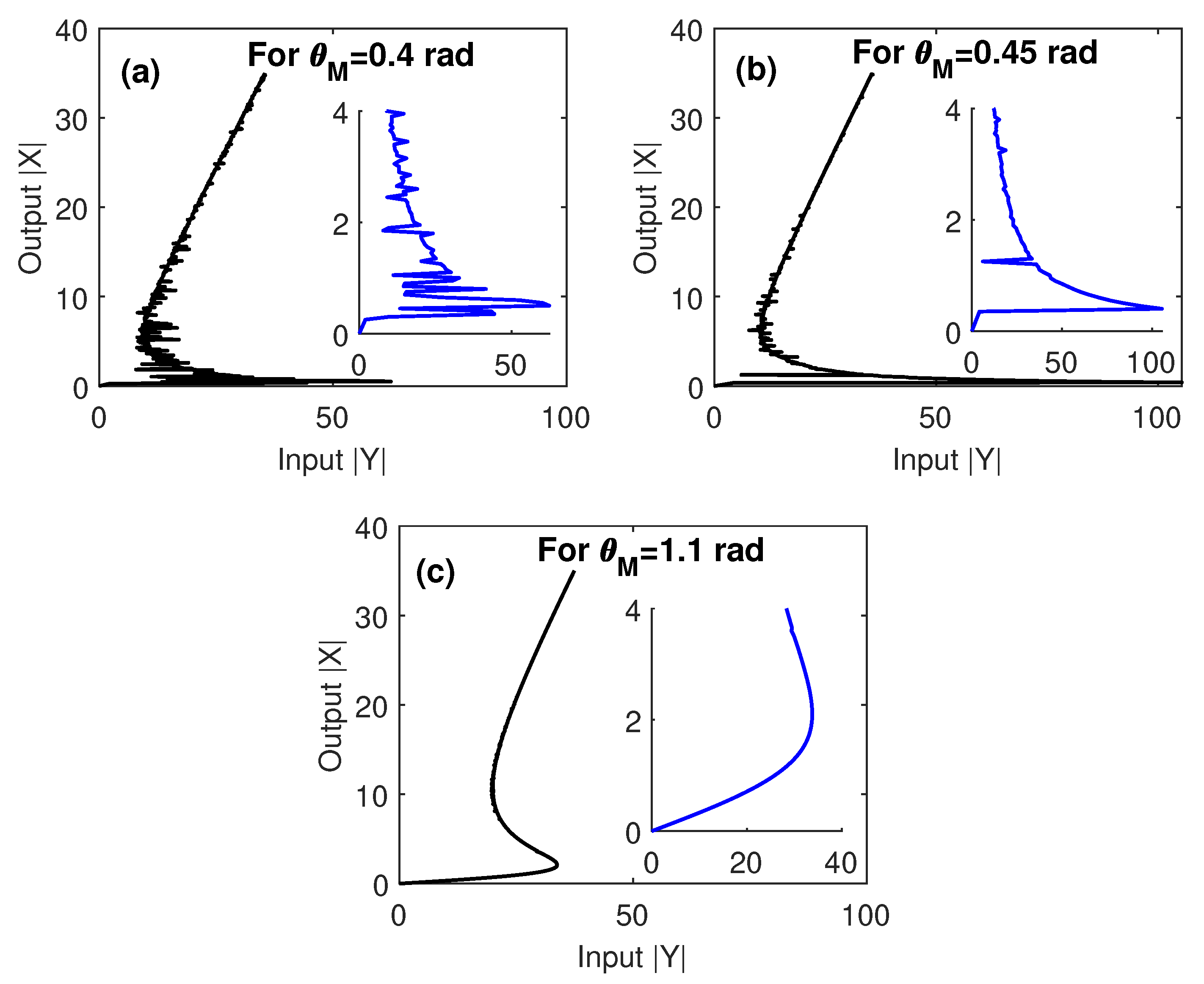
In order to compare the sensitivity of the optical multistability to the geometry of the system via manipulating the edge-to-edge distances between MNP and GND, and the inclination angle of the two components with respect to QD, we checked in
Figure 3 the output–input relationship at different values of
. We observed that a small
led to a large number of loops of multistability with relativity low threshold. As
increases, the degree of multistability decreases, while the threshold increases. It is clear that the optical multistability of the MNP–GND–QD hybrid system exhibits high sensitivity to
, since increasing the latter by
rad leads to doubling the optical multistability threshold. Moreover, a transition between optical multistability and bistability is shown at relativity large
, where
. This is due to the large center-to-center distances between GND and QD obtained in this case as noted by Equation (3).
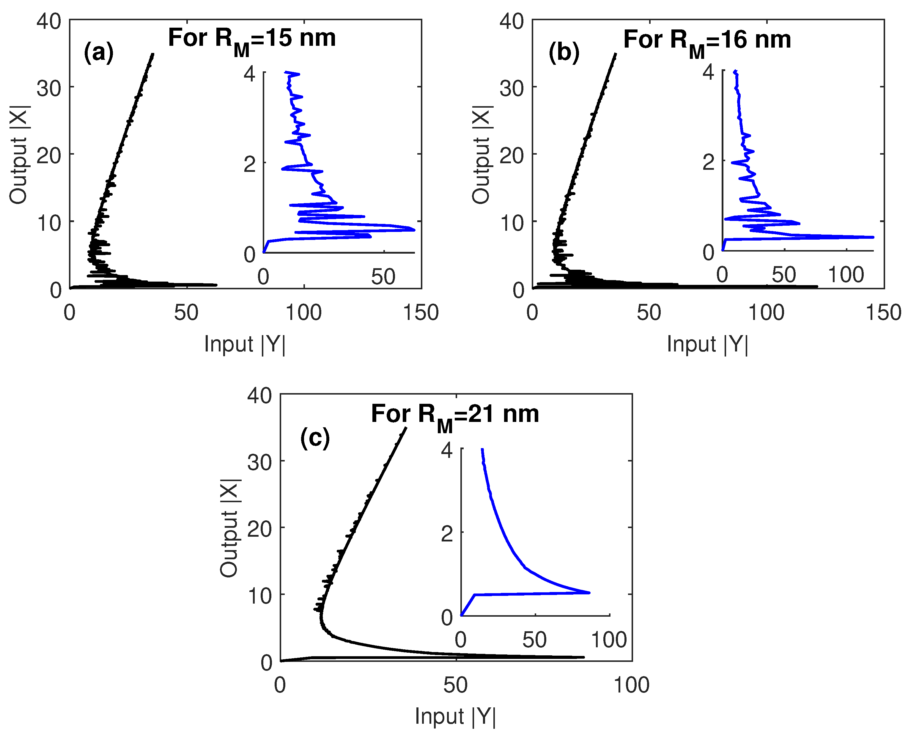
The effect of the size of MNP is investigated in
Figure 4. The threshold size of MNP required to get a high degree of multistability with a low threshold is that of radius equal to
of the center-to-center distance between MNP and GND; i.e.,
nm, which has been used in
Figure 4. Increasing the size of MNP leads to decreasing the degree of optical multistability and increasing its threshold. This can be attributed to the large associated center-to-center distances between MNP and GND that strongly decrease the enhancement factor
, as observed by Equation (2), in addition to the large corresponding center-to-center distances between GND and QD that lead to a reduction of the energy transfer between the two components. For this reason, when we set the size of MNP to
of the center-to-center distances between MNP and GND, we observed a switching between optical multistability and bistability, as shown in
Figure 4c.
It is worth noting here that the tolerance intervals for the critical parameters that our system can afford without losing the optical multistability performance are almost reasonable. In particular, the system still demonstrates optical multistability with edge-to-edge distances between MNP and GND
in the range 5–17 nm (
Figure 2), an inclination angle of MNP (
) in the range 0.4–1.1 rad (
Figure 3) and a radius of MNP
in the range 15–21 nm (
Figure 4).
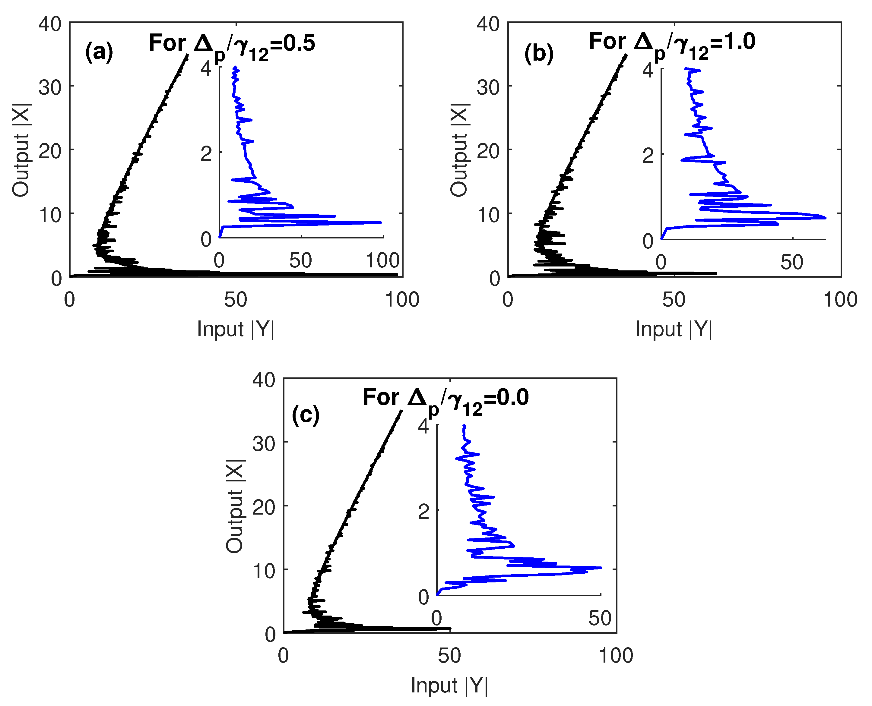
To figure out how the optical multistability of our proposed system can be controlled by the detunings of probe and control fields, we plot in
Figure 5 and
Figure 6 the relationships between the output and input fields at different values of
and
.
Figure 5 shows the control of optical multistability of the MNP–GND–QD hybrid system by the detuning of the probe field. It is clear from
Figure 5c that, when the probe field is resonant with the atomic transition
, the threshold of multistability is significantly reduced while the number of its loops is increased. This seems reasonable since a strong coupling between GND and QD is induced at resonance resulting in the enhancement of the nonlinearity of the proposed hybrid system and a reduction in the input field required to trigger the optical multistability. Moreover, if the damping rate of excited state
exceeds the detuning of the probe field, the threshold of optical multistability is relatively large (
Figure 5a) and decreases as the ratio
increases (
Figure 5b).
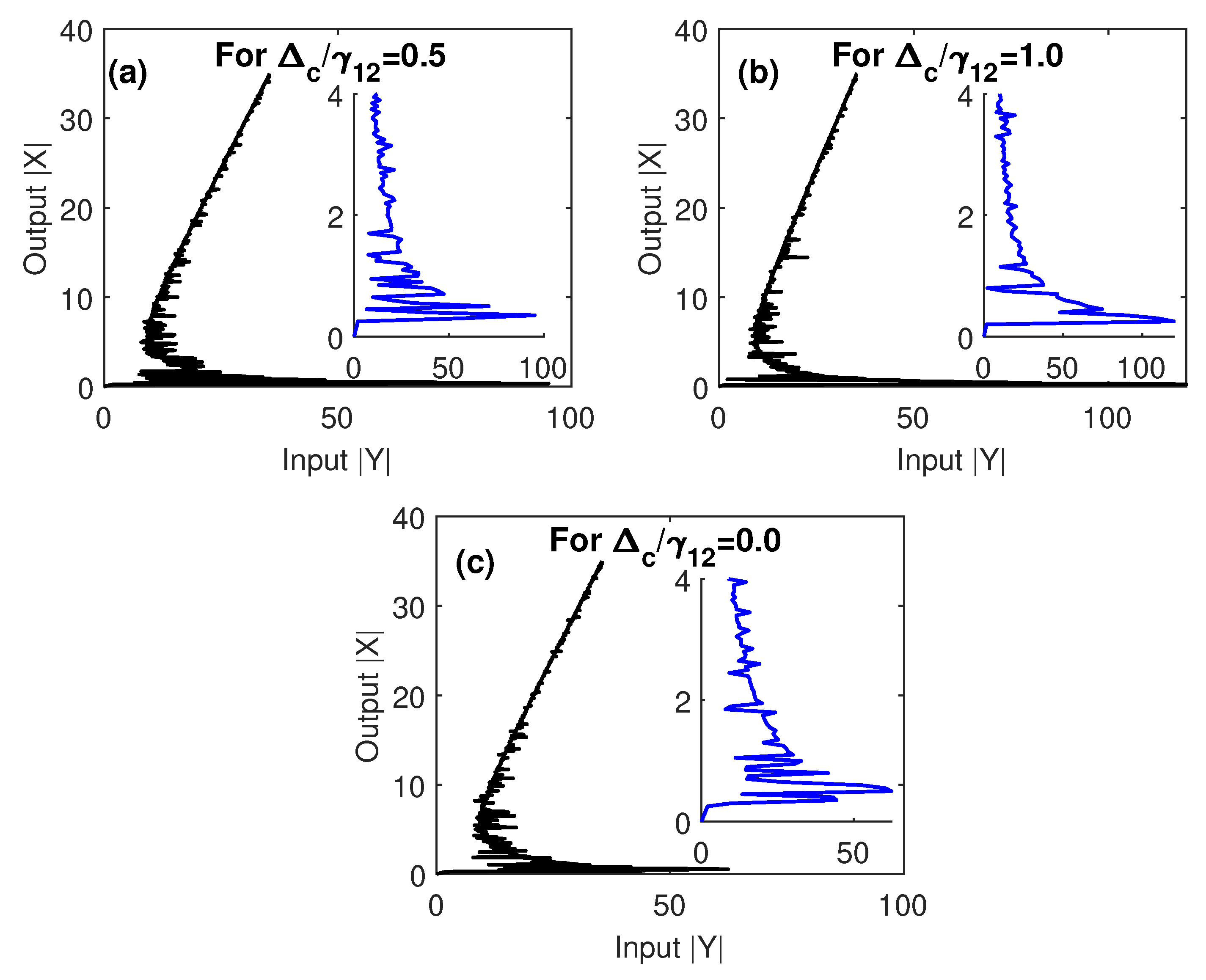
On the other hand, we examine in
Figure 6 the extent to which the optical multistability of the proposed MNP–GND–QD can be controlled by the detuning of the control field that does not circulate in the optical ring cavity. Compared to
Figure 5, with a resonant control field, similar results were found, but different behavior was observed for off-resonant control field. Specifically, we observed that the threshold of optical multistability was relatively small for the case of
(
Figure 6a). Interestingly, the case of resonant probe and control fields that is depicted in
Figure 5c shows an extremely low threshold of optical multistability due to the enhanced energy transfer associated with two-photon detuning [
41].
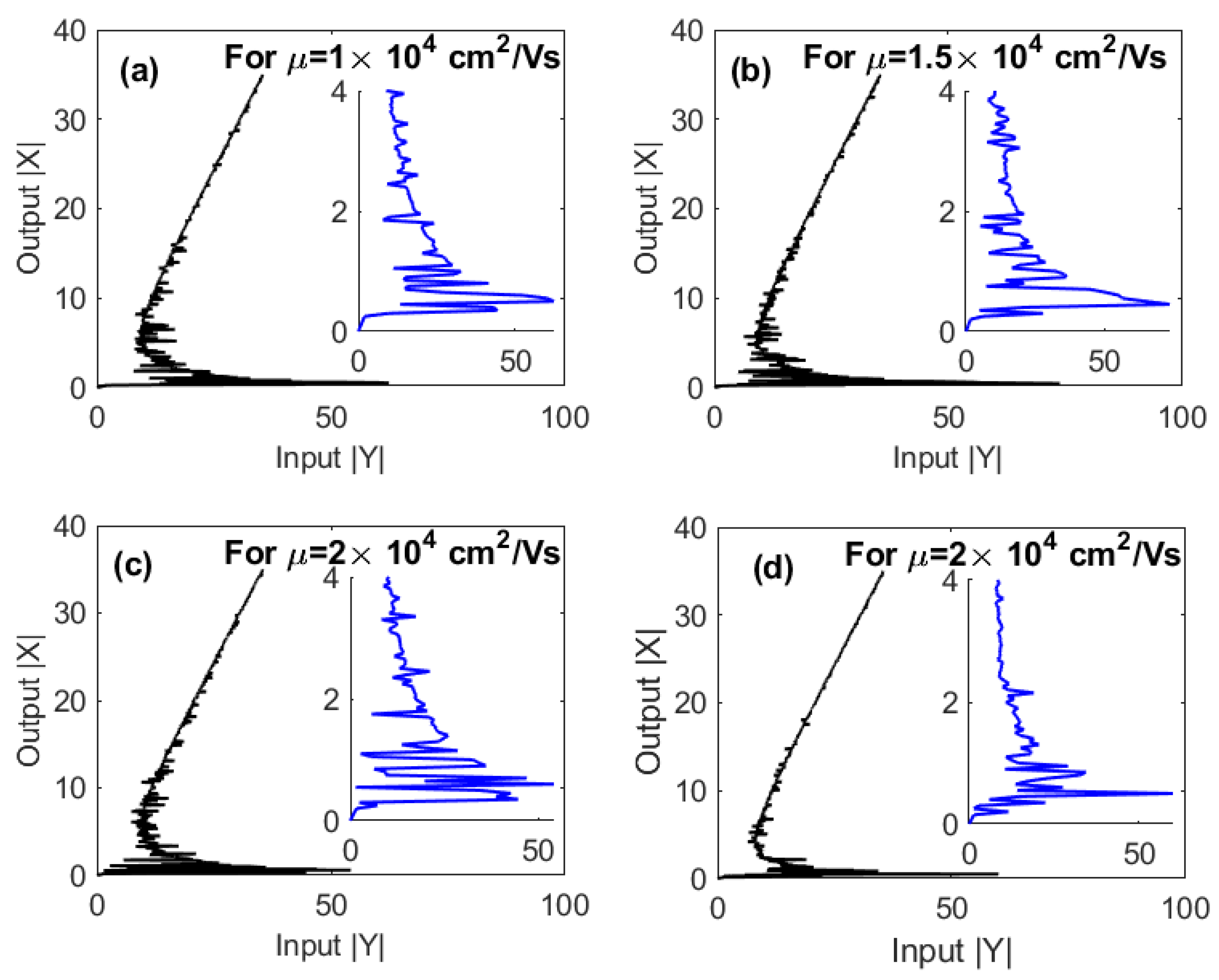
One of the unique properties of graphene that controls the magnitude of the extinction cross-section and the energy of graphene plasmons is the mobility of graphene charge carriers (
). However, due to the high carrier mobility in graphene, the different values of (
) with the same order of magnitude can lead to the same energy of plasmons. Therefore, we can safely change the values of the mobility while ensuring that the energy of GND plasmons remains resonant with excitons in the QD.
Figure 7 shows the effect of the graphene carrier mobility on the optical multistability. It can be seen that the number of loops increases while the threshold of multistability decreases as the mobility of graphene increases. This result can be understood based on the relation between the relaxation rate of graphene plasmons and the mobility of its charge carriers, i.e.,
. In other words, higher mobility means lower damping rate of graphene plasmons that can enhance the nonlinearity of the system.
Based on the above results for optical multistability under EIT conditions, it is remarkable that an extremely low threshold of optical multistability can be obtained for a resonant probe field that induces the plasmons of a relatively large-mobility GND as shown in
Figure 5c and
Figure 7d, compared to those have been found for MNP-QD hybrid system [
26].
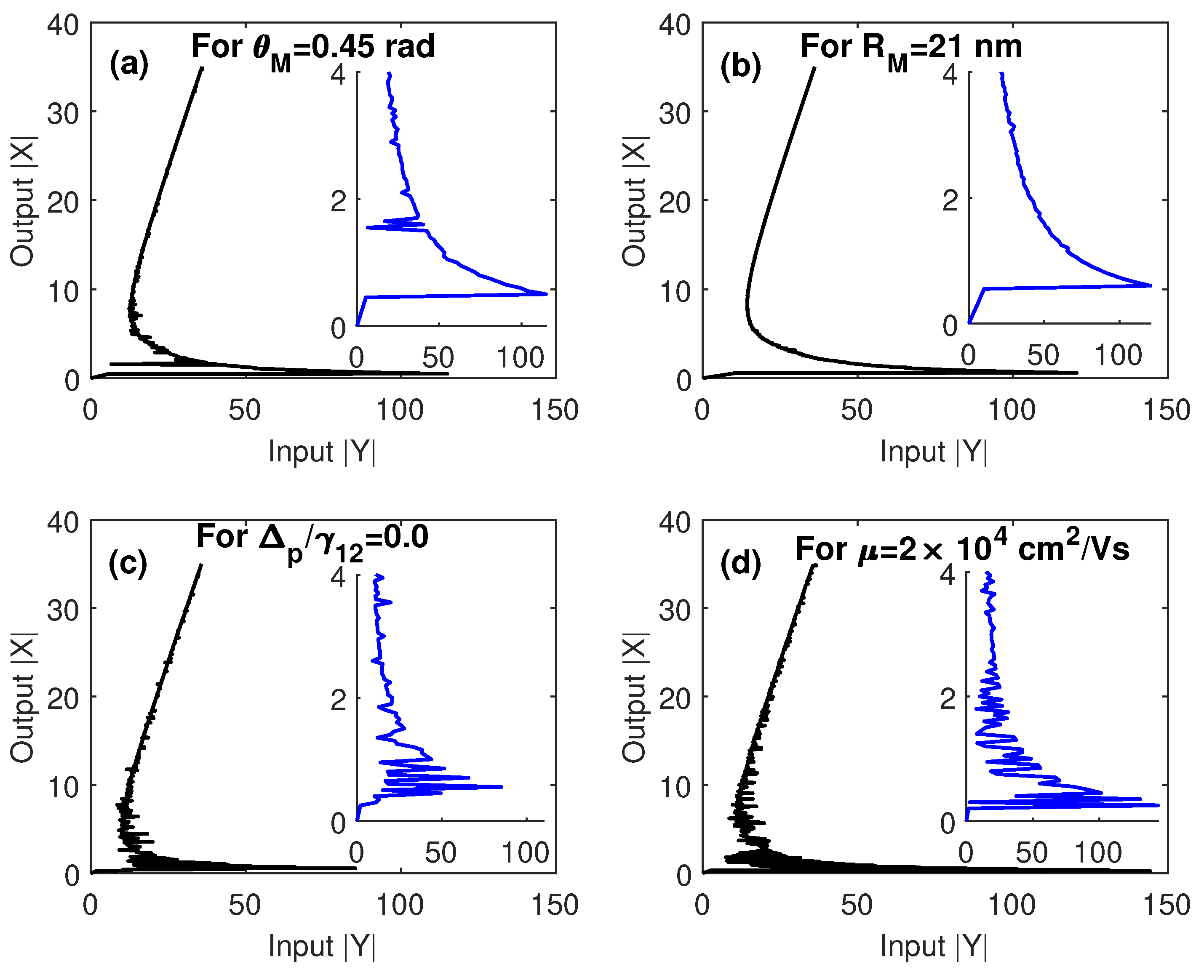
Finally, in
Figure 8 we show some of the above multistability curves when the conditions of EIT are not fulfilled; i.e.,
, and
. From these results, it can be seen that under conditions of EIT, the multistability threshold is significantly reduced because of the enhanced nonlinearity induced by steep dispersion associated with EIT. On the other hand, the limits of the parameters within which the switching between optical multistability and bistability can occur, are unaffected, as shown in
Figure 8b. Taking into account all cases examined in
Figure 8, we can conclude that when EIT conditions are not fulfilled, we can obtain a relatively low threshold for multistability only for a resonant probe field (
Figure 8c). This is apparently due to the strong energy transfer between plasmons in GND and excitons in the QD for resonant probe field.


