Article

Electronic Constant Twist Angle Control System Suitable for Torsional Vibration Tuning of Propulsion Systems

Faculty of Mechanical Engineering, Technical University of Košice, Letná 9, 042 00 Košice, Slovakia
*
Author to whom correspondence should be addressed.
J. Mar. Sci. Eng. 2020, 8(9), 721; https://doi.org/10.3390/jmse8090721
Submission received: 28 August 2020 / Revised: 9 September 2020 / Accepted: 17 September 2020 / Published: 18 September 2020
(This article belongs to the Special Issue Marine Engines Performance and Emissions)

Abstract

:
Currently, great emphasis on reducing energy consumption and harmful emissions of internal combustion engines is placed. Current control technology allows us to customize the operating mode according to the currently required output parameters, while the tuning of mechanical systems in terms of torsional vibration is often ignored. This article deals with a semi-active torsional vibroisolation system using pneumatic flexible shaft coupling with constant twist angle control. This system is suitable, as it is specially designed, for the tuning of mechanical systems where the load torque has fan characteristics (fans, ship propellers, pumps). The main goal of this research is to verify the ability of an electronic control system developed by us to maintain the pre-set constant twist angle of the used pneumatic flexible shaft coupling during operation. The constant twist angle control function was tested on a laboratory torsional oscillating mechanical system. Presented results show that the proposed electronic control system meets the requirements for its function, namely that it can achieve, sufficiently accurately and quickly, the desired constant twist angle of the pneumatic flexible shaft coupling. It is possible to assume that the presented system will increase the technical level of the equipment where it will be applied.

1. Introduction

Nowadays, reducing energy consumption and harmful emissions of internal combustion engines is a very important issue addressed by both research institutions and manufacturers of internal combustion engines. Development of control technology allows us to customize the operating mode of the device according to the currently required output parameters, while often the tuning of mechanical systems in terms of torsional vibration is ignored [1,2,3,4,5,6]. Tuning current mechanical drives in terms of torsional vibration by conventional (passive) vibroisolation methods is increasingly problematic. This is mainly due to operation in a wide range of speeds, uneven operation cylinders (deactivated cylinders, uneven fuel supply to the cylinders) and also the increased value of excitation amplitudes.
Vibroisolation methods can be divided according to what extent there is a controlled change of system parameters and according to energy supply requirements during operation of [7,8]: passive vibroisolation, where the dynamic parameters of the mechanical system cannot be actively changed and these solutions do not require additional energy for their function; semi-active vibroisolation, also called as adaptive vibroisolation, where it is possible to change basic parameters such as torsional stiffness, damping coefficient and mass moment of inertia, and these vibroisolation systems need energy during the change of their parameters; and active vibroisolation, where an additional dynamic torque component is introduced into the system, and these vibroisolation systems need constant power supply during the operation of the mechanical system.
In the case of passive vibroisolation, the system is pre-tuned in terms of torsional vibration in such a way that the system parameters such as torsional stiffness of shafts (depending on their diameter) or mass moment of inertia (e.g., by adding a flywheel) are suitably adjusted. Another way is to use special devices such as flexible shaft couplings, vibration absorbers and dampers. In this method of torsional oscillating mechanical systems tuning, the properties of the system are predetermined. However, it should be noted that the properties of these elements (apart from flywheels and pendulum vibration absorbers) may change over time, causing the mechanical system to be not tuned properly. Viscous dampers contain fluids such as silicon oils whose properties change over time. Due to high temperatures, the used liquid may solidify, causing the damper to lose its function completely [9]. Flexible couplings with rubber elastic elements can significantly change their properties depending on the static torque, operating temperature, the number of operating cycles during operation and also due to the aging of the used rubber material [10,11,12].
Semi-active vibroisolation systems use devices with the possibility to change their mechanical parameters affecting the size of torsional vibration (torsional stiffness, damping coefficient and moment of inertia). Devices using a change of torsional stiffness include some types of already manufactured shaft couplings such as pneumatic flexible shaft couplings [13,14,15] and magnetic shaft couplings [16,17]. Moreover, in the field of robotics, attention is currently paid to elements with variable torsional stiffness (variable stiffness actuators, variable stiffness joints) and variable damping devices too. Although the use of these devices is expected mainly where there may be an unexpected collision with surrounding objects or humans (e.g., household robots), there is a possibility to utilize their principles in the field of mechanical drives too. A fairly comprehensive overview of these elements can be found in [18]. Devices with variable mass moment of inertia include flywheels containing weights, whose center of gravity in the radial direction relative to the axis of rotation can be shifted [19]. Alternatively, they contain a fluid mechanism [20].
Active vibroisolation systems are developed mostly in the form of design concepts (patents), though some were verified theoretically by dynamic model simulations or by simplified physical models in laboratory conditions, but gradually they are already beginning to be verified in real ship propulsion systems as well [8]. To eliminate torsional vibrations in real time, it is proposed to use devices such as electrodynamic brakes [21,22,23], piezoelectric dampers [24] and inertial mass actuators [8], which introduce additional torque to the system. The time course of the additional torque is proposed mostly as harmonic [7,8] or as periodic pulses [21,23].
This article deals with a semi-active vibroisolation system using pneumatic flexible shaft coupling with constant twist angle control. This system is suitable, as it is specially designed, for tuning mechanical systems where the load torque has a fan characteristic when the load torque is approximately proportional to the square of the rotational speed (fans, ship propellers, centrifugal pumps) [25].
The main goal of this research is to verify the ability of an electronic constant twist angle control system (ECTACS), developed by us, to maintain a pre-set constant twist angle of the used pneumatic flexible shaft coupling during operation of an experimental torsional oscillating mechanical system (TOMS) in laboratory conditions.

2. Materials and Methods

2.1. Pneumatic Flexible Shaft Couplings

At our department, new types of pneumatic flexible shaft couplings are being developed [15]. The dynamic torsional stiffness of these couplings can be continuously changed by changing the air pressure in their pneumatic flexible elements. They also show less changes in properties due to the aging of the material of the elastic elements, because the elastic elements have low rigidity and most of the load is transmitted by the compressive force of the air [13]. Pneumatic flexible shaft couplings can be used for tuning torsional oscillating mechanical systems in two main ways [13,14,15]:
(1)
Tuning, where the value of pressure is pre-set to a suitable value out of operation. In this case, the pneumatic flexible shaft coupling works as a classical shaft coupling with option to adapt its torsional stiffness out of operation. However, it still represents a passive vibroisolation system.
(2)
Continuous tuning, where the pressure is adjusted (via the control system) to current operating conditions directly during operation. Thus, the pneumatic flexible shaft coupling in this case acts not as a classical shaft coupling, but it can be considered as a pneumatic tuner of torsional oscillations (PTTO) used as an element for the realization of semi-active vibroisolation.
Several methods of continuous tuning using pneumatic tuners of torsional oscillations were proposed and patented [26]. The two main continuous tuning methods, which were also practically implemented in laboratory conditions, are extremal control [27] and constant twist angle control [13].

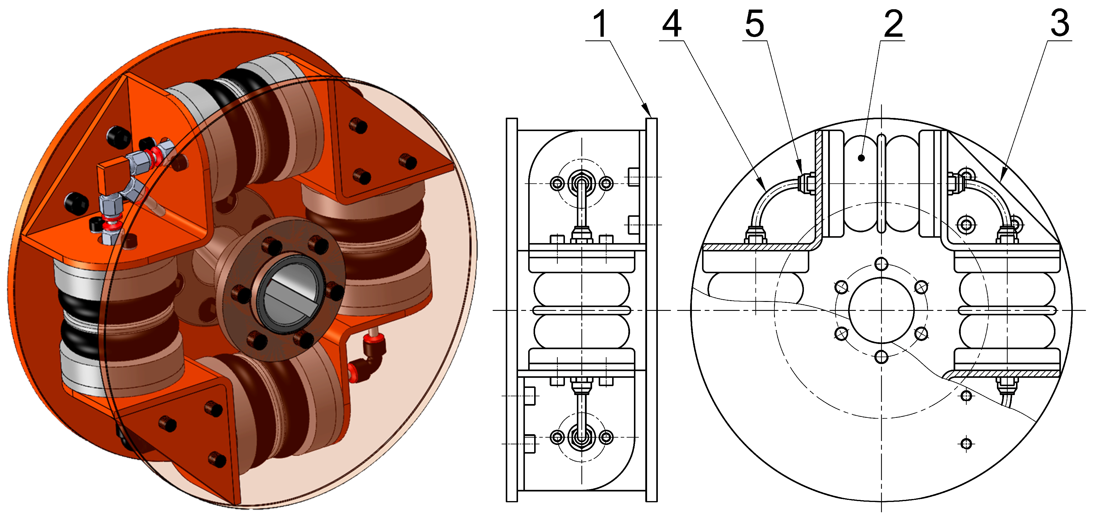
2.1.1. Used Pneumatic Tuner of Torsional Oscillations

In the presented research, a tangential pneumatic tuner of torsional oscillations with fully interconnected flexible elements with a 4–2/70–T–C-type designation was used (Figure 1). This type of designation means that the PTTO has 4 double-bellows flexible elements with an outer diameter of 70 mm, the elements are placed tangentially and their compression spaces are fully interconnected. This PTTO consists of two identical hubs (1) connected by pneumatic flexible elements (2). The individual pneumatic flexible elements are mounted between triangular consoles (3). Under loading torque, one pair of opposing pneumatic flexible elements is stretched and at the same time the other pair is equally compressed, allowing the PTTO to transmit torque in both directions of rotation. The compression space of the PTTO is fully interconnected by polyamide hoses with a diameter of 6 mm (4). Its filling with gaseous medium is realized through a rotary air supply, which is a part of one of the connecting flanges of the PTTO. Each flexible element includes two pneumatic screw connections (5).
In order to react flexibly with the variable load torque generated directly during the operation of the mechanical system, it is necessary to ensure that the pressure in its entire compression space changes as quickly and evenly as possible. This is ensured by the full interconnection of pneumatic elements compression spaces. The speed and uniformity of the filling of the compression space can be influenced by increasing the inner diameter of the connecting hoses too, but at the expense of reducing the resistance to the air flow between the pneumatic flexible elements. In practice, however, this means a reduction in the damping properties of the PTTO itself [28,29].
Generally, the static load torque of pneumatic couplings Mstat [N·m] at a twist angle φ [rad] can be expressed as [30]
M s t a t = M G ( φ ) + p T · ( S e · r ) ( φ ) ,
where MG(φ) [N·m] is the pneumatic flexible element rubber shell torque, pT [Pa] is the overpressure in the pneumatic flexible elements of the coupling, Se [m2] is the effective area of the coupling’s compression space and r [m] is the distance of the center of the effective area Se from the coupling’s axis. Expression Se·r [m3] is then the static moment of the effective area to the coupling’s axis. Rubber shell torque and static moment of effective area are expressed as a function of the twist angle φ. The parameters MG and Se·r can be determined from measured static load torque—static load characteristics (Figure 2a) and overpressure (Figure 2b) depending on the twist angle φ at different initial overpressures. The full procedure of obtaining these parameters is described in [30].
In Figure 3, the resulting rubber shell torque MG (Figure 3a) and effective area of the coupling compression space Se·r (Figure 3b) in graphical and equation form are shown [28].
The model shows good agreement with the actual PTTO, as the difference between the calculated and measured values of the static load torque does not exceed 5% [28]

2.2. Constant Twist Angle Control

The principle of constant twist angle control is that it maintains a pre-set constant static twist angle of the PTTO [31]. This is ensured by a control system which adapts the overpressure of the gaseous medium in the PTTO to the static load torque in order to maintain the pre-set constant twist angle. Constant twist angle control is suitable for tuning mechanical systems with fan characteristics. The principle of operation is explained in more detail below [32].
The transmitted static load torque Mstat and dynamic stiffness kdyn [N·m·rad−1] of the PTTO by a given constant twist angle φconst (for simplicity neglecting the rubber shell torque MG which is relatively small compared to the total transmitted torque [13]) can be generally considered as proportional to the overpressure pTC in the compression space of the PTTO corresponding to the given constant twist angle (see Equation (1)).
Thus, the static load torque can be expressed as
M s t a t = a ( φ c o n s t ) · p T C
and dynamic torsional stiffness as
k d y n = b ( φ c o n s t ) · p T C ,
where a ( φ c o n s t ) [N·m·Pa−1] and b ( φ c o n s t ) [N·m·rad−1·Pa−1] are factors whose values depend on the constant twist angle φconst only.
The transmitted static load torque corresponding to the fan characteristics (of the propeller) can be expressed as
M s t a t = c f · ω 2 ,
where cf [N·m·rad−2·s2] is a constant and ω [rad·s−1] is the angular speed of the propeller shaft.
From the equality of Equations (2) and (4) for the static load torque Mstat, then expressing pTC and putting it into Equation (3), the dynamic torsional stiffness will be
k d y n = b ( φ c o n s t ) · c f a ( φ c o n s t ) · ω 2 .
Considering a two-mass torsional oscillating mechanical system with dynamic torsional stiffness kdyn and equivalent mass moment of inertia IRED [kg·m2], the natural angular frequency of this system will be
Ω 0 = k d y n I R E D = b ( φ c o n s t ) · c f a ( φ c o n s t ) · I R E D · ω = C ( φ c o n s t ) · ω ,
where C ( φ c o n s t ) [-] is a factor depending on the given constant twist angle φconst only. This means that the natural frequency of the mechanical system will be proportional to the angular speed of the propeller shaft, and the value of factor C ( φ c o n s t ) can be properly set by selecting a suitable constant twist angle φconst. This is illustrated with an interference diagram of a two-mass torsional oscillating mechanical system using the PTTO with linear characteristics in Figure 4, where ω is the angular speed of the shaft, ωe1 and ωe2 are the excitation frequencies resulting from the periodically alternating load torque and Ω0const1…8) are the natural frequencies corresponding to the pre-set constant twist angles φconst1 < φconst2 < … < φconst8. The intersections of the excitation frequencies with the natural frequency represent resonances at which the transmitted load torque reaches its maximum value. The case of resonance should be avoided in the operating speed range, as it can be dangerous in terms of a high alternating load torque.
According to Figure 4, the course of natural frequencies consists of three parts. The first part, the sub-regulatory area, is a horizontal line beginning at zero speed when the load torque is zero (resulting from the fan characteristics) and the PTTO is inflated to the minimum operating pressure. At a certain speed, the torque twists the PTTO to the selected constant twist angle, and this is the start of the second part representing the regulatory area of the PTTO. In the regulatory area, the pressure in the PTTO is regulated to a value where the PTTO has the desired constant twist angle. The regulatory area ends at a speed when the pressure reaches the maximum operating value. This point is the start of the over-regulation area. After this point, the pressure has its maximum operating value. In the presented case, the optimum constant twist angle is φconst4, where the torsional natural frequency is farthest from the excitation frequencies, i.e., farthest from the resonance in the regulatory area of the PTTO.
Results of theoretical analyses in marine propulsion mechanical systems using constant twist angle control presented, for example, in [31,33] show that this type of control ensures proper tuning in terms of torsional vibration and has considerable potential for future application.
Constant twist angle control can be ensured by a constant twist angle regulator which is a part of the PTTO [13,26], or ECTACS can be used.

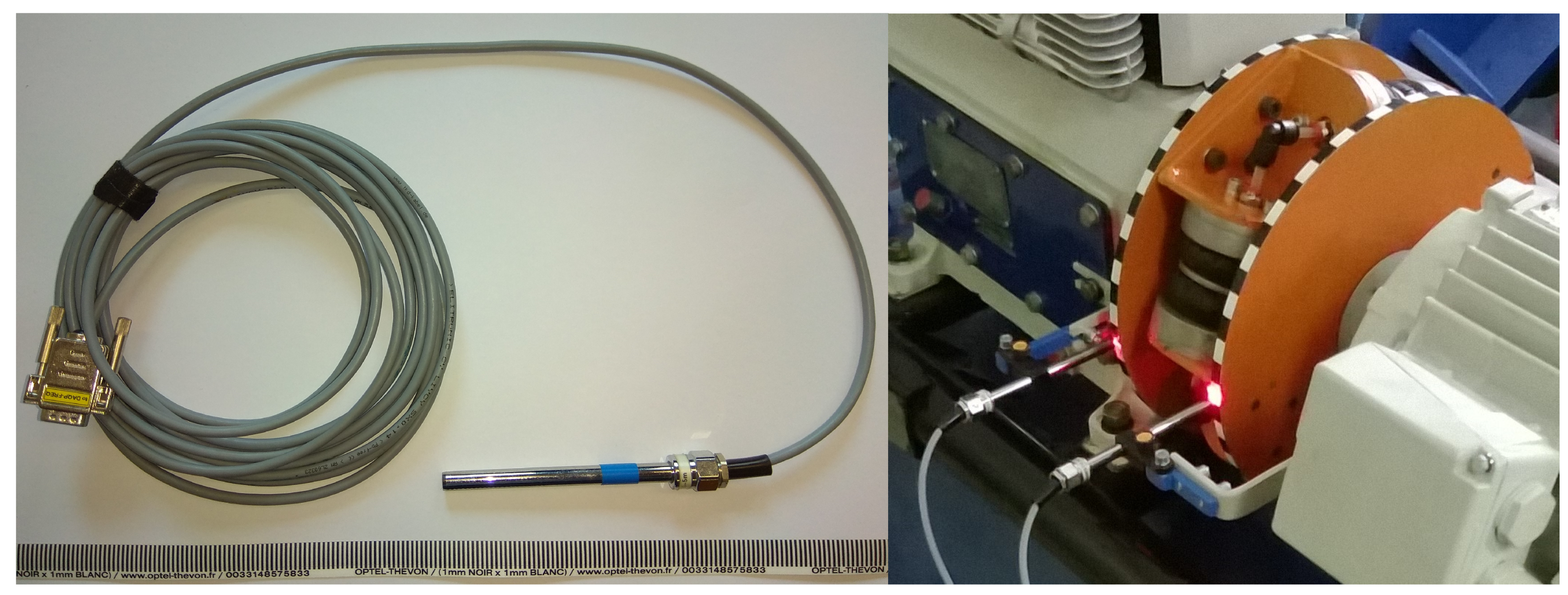
2.3. Experimental Torsional Oscillating Mechanical System

In order to verify the ability of our ECTACS to keep the twist angle of a PTTO at a pre-set constant value, the ECTACS was applied into an experimental torsional oscillating mechanical system.
The TOMS of the piston compressor drive (Figure 5) is made up of a 3-phase asynchronous electromotor, Siemens 1LE10011DB234AF4-Z (11 kW, 1500 RPM) (1). Rotational speed of this electromotor is continuously vector-controlled by a frequency converter, Sinamics G120C. The electromotor drives a 3-cylinder piston compressor, ORLIK 3JSK-75 (3), through a PTTO type 4-2/70-T-C (2) (Figure 1). The compressor in this system acts as a load and torsional vibration exciter too. For proper tuning of the system, it is necessary to know the dynamic behavior under different operating conditions, which was experimentally investigated in [34].
Under standard conditions, the load torque of the system has no fan characteristics, and this means that this TOMS is not very suitable for tuning torsional vibrations with constant twist angle control, so our goal is not the tuning itself but only the verification of the ability to maintain the desired constant twist angle of the PTTO.
The whole drive is mounted on a rigid sprung frame. The compressed air from the compressor flows into an air pressure tank with a volume of 20 l. The air pressure in the tank is controlled by a throttling valve. So, the load of the TOMS can be adjusted. Maximum compressor output air overpressure is 800 kPa and its value is measured by a pressure sensor, Danfoss MBS 3000, with an overpressure measuring range of 0–1 MPa. The same type of pressure sensor is used for measuring the air pressure value in the compression space of the PTTO. The accuracy of the MBS 3000 sensor with a metal membrane is 0.5% of its measuring range, i.e., 5 kPa (combined fault–nonlinearity, hysteresis and reproducibility). The supply of compressed air into the PTTO is ensured by a rotation supply (4). The mechanical part of the experimental TOMS is described in more detail in [35].
The multifunctional electronic module (MFEM), marked with the number (5), which is a part of an electronic constant twist angle control system, developed by us, has the following functions: Page: 7 Is the italics necessary?
(1)
Power supply for the optoelectronic sensors, pressure sensors and electromagnetic valves;
(2)
Measurement of the black-to-white stripe edge-crossing times for both hubs of the PTTO;
(3)
Measurement of the air pressure value in the compression space of the PTTO and the compressor output air pressure value;
(4)
Communication with the software part (running in a PC) of our ECTACS. The measured data are sent to the PC in order to be further processed in real-time;
(5)
Setting of the needed value of the air pressure in the compression space of the PTTO, which is computed by the software part of our ECTACS. The quick and very accurate pressure setting is carried out by electromagnetic valves, one for the inflation and one for the deflation of the compression space of the PTTO.

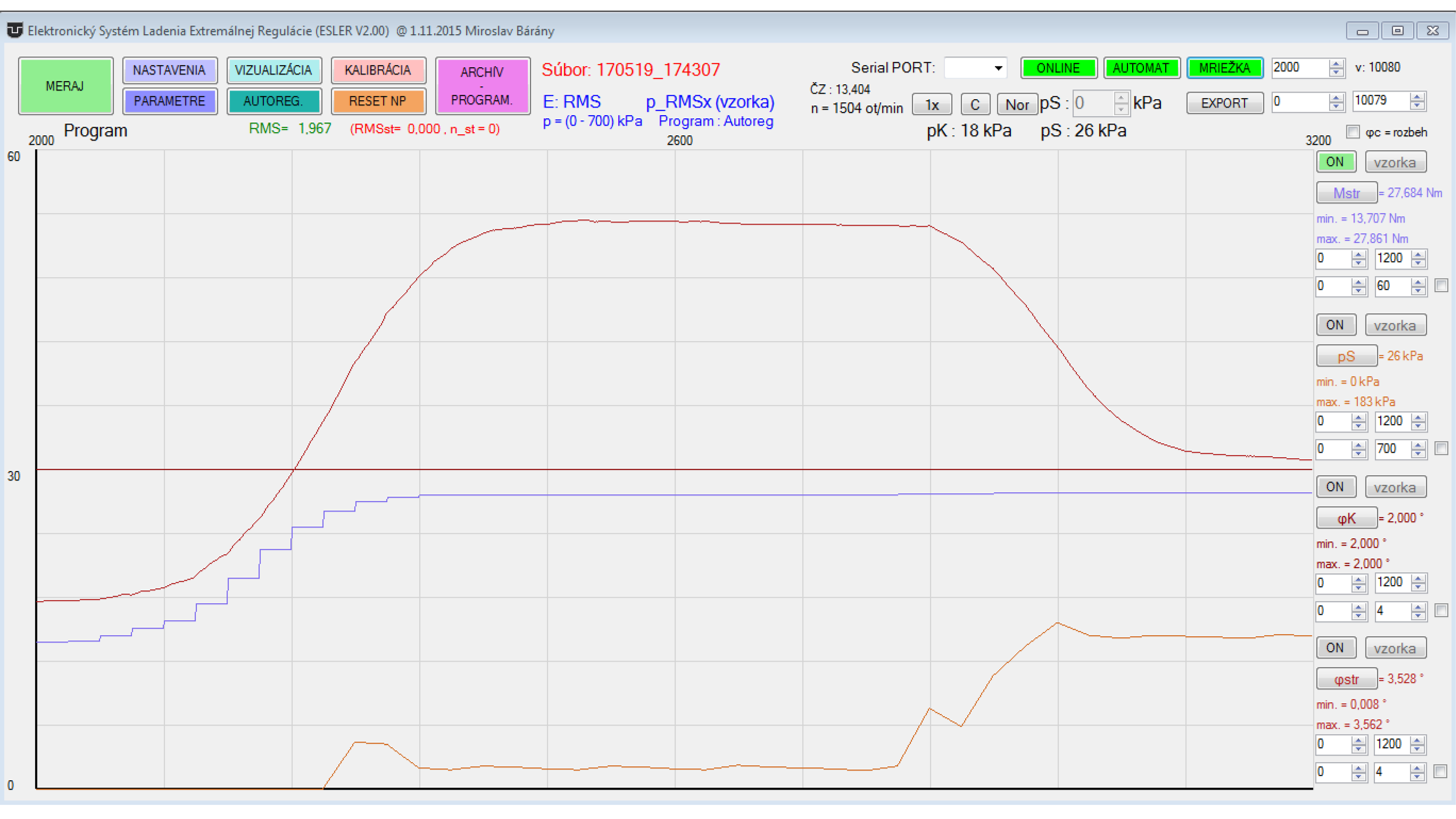
2.4. Data Measuring and Processing

The dynamic load torque transmitted by the PTTO causes mutual dynamic angular twisting of the driving and driven hubs of the PTTO. The measurement is based on determining the PTTO’s twist angle time course. The PTTO is equipped with black–white tape, which is stuck to the circumference of the driving and driven hubs of the PTTO and they are scanned by a pair of optoelectronic sensors (Figure 6). According to our specific requirements, a pair of Dewetron optoelectronic sensors of type SE-TACHO-PROBE-01 [36] (Figure 6) was used.
These sensors detect the reflection from the reflective black–white moving tape (Figure 6b). The sensors react to the edges between the black and white stripes. There is a distinct change of electrical output voltage at the moment the edge is crossed. These sensors can work with a maximum frequency of 10 kHz but the cleanness of the reflective tape, cleanness of the optical parts of the sensors and the sharpness of the edges between the black and white stripes must be excellent [36].
The number of black and white stripe pairs for the driving and driven hubs should be equal and chosen with respect to the maximum twist angle of the PTTO and to the character of the transmitted load torque (especially its dynamic component). It is also important that the length of all the black and white stripes should be equal. The angle corresponding to length of a black and white stripe pair must be larger than the maximum twist angle of the PTTO. For the PTTO type 4-2/70-T-C, the maximum twist angle is 11° which corresponds to a maximum of 32 pairs of stripes. Further, as the major harmonic component for a three-piston compressor is the 3rd harmonic component, it is advantageous to select the number of black and white stripe pairs as integer multiples of 3 to obtain the best results for the twist angle time course by the equal operation of all cylinders (theoretically “3 identical recorded curve portions in one revolution”). Therefore, 30 black–white stripe pairs for each hub of the PTTO have been selected. The edge-crossing times ti need to be measured, where the index i stands for the sample order number. In our case, only the black-to-white stripe edges are considered. The times ti are computed from the counted number of impulses from the counter of the MFEM microprocessor. One impulse represents a time of 1/14745600 s.
Considering the times t1i for the driving hub and the times t2i for the driven hub of the PTTO, the time delays ∆ti [s] can be computed using the following equation:
Δ t i = t 2 i t 1 i .
In the next step, the total twist angle φT [rad] of the PTTO can be computed according to the following equation:
φ T i = π · n · Δ t i 30 ,
where n [min−1] is the immediate rotational speed of the mechanical system.
From the total twist angle of the PTTO φT, its static component φstat can be computed as the mean value:
φ s t a t = i = 1 k φ T i k ,
where k [-] is the number of samples, which has to be an integer multiple of the black–white stripe pairs number on the hub. In practice, the floating average method is used for this computation.
The computations according to Equations (7)–(9) are performed by the software part of our ECTACS in PC in real time. This way, the controlled variable (φstat) for the ECTACS can be computed. It is very advantageous because the torsional vibration does not directly affect the control device like in the case of regulators directly built into the PTTO.

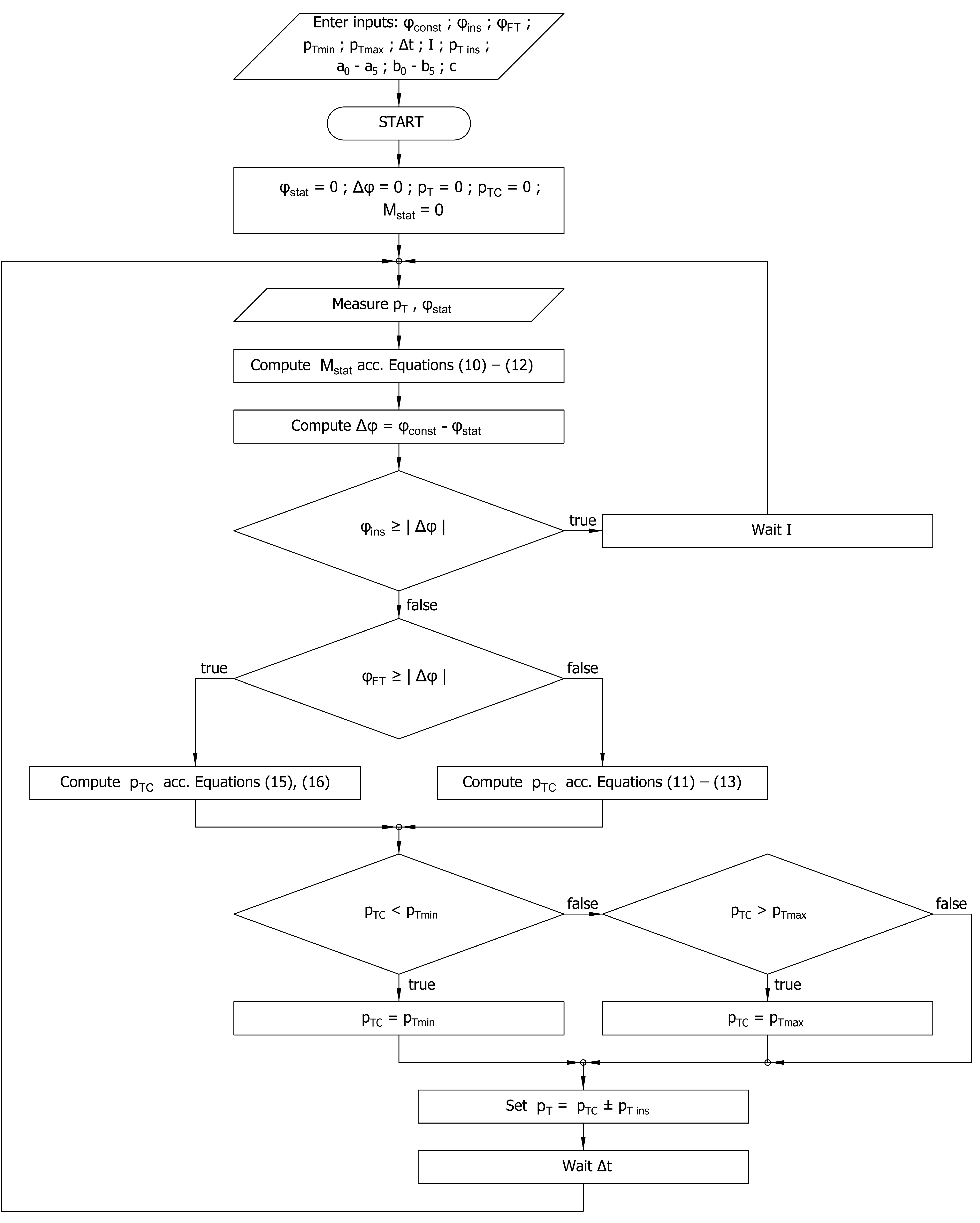
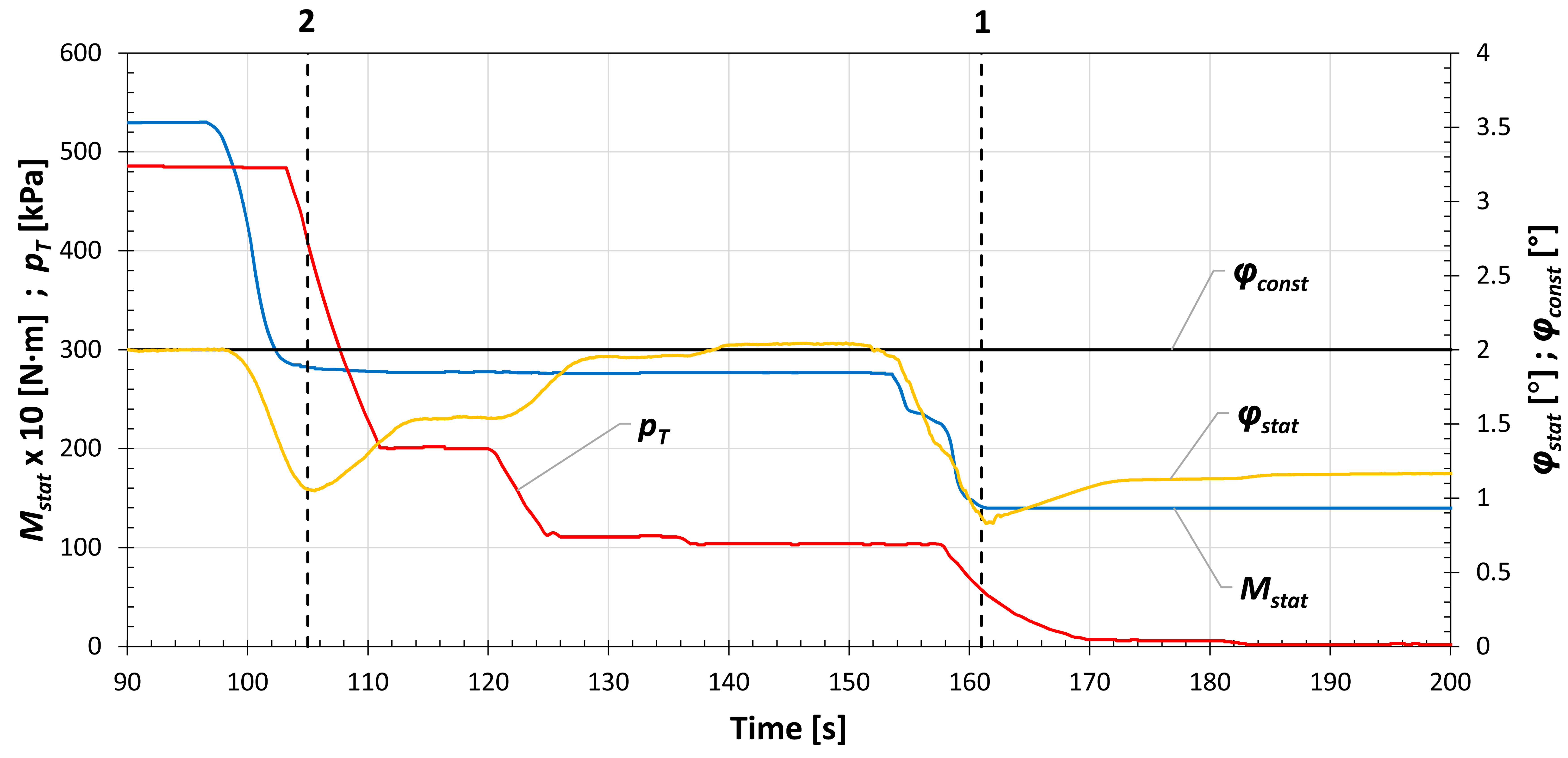
2.5. Description of the Constant Twist Angle Control System Function

The goal of constant twist angle control is to maintain a pre-set static (mean) value of the twist angle by any given static load torque Mstat resulting from the current operating mode. Although it is possible to use a closed-loop PID control system with a static twist angle as a controlled variable and overpressure as a manipulated variable, based on the fact that the mathematical and physical model of the PTTO (presented in Section 2.1.1) is well known, it was decided to use a model-based adaptive control system [37]. This approach allows us to reach the desired value of the static twist angle more quickly, which is very important in terms of passing through the resonance as quickly as possible.
The static load torque of the PTTO at a periodically alternating load torque can be computed as
M s t a t = M G ( φ s t a t ) + p T · ( S e · r ) ( φ s t a t ) ,
where pT is the mean overpressure in the PTTO, and the values of the rubber shell torque MG and static moment of effective area Se·r are computed from the static twist angle φstat. The value of the twist angle is continuously measured and its mean value is computed by the control system.
The rubber shell torque MG(φstat) and the static moment of effective area Se·r(φstat) are computed as fifth degree polynomials:
M G ( φ s t a t ) = i = 0 5 a i · φ s t a t i ,
( S e · r ) ( φ s t a t ) = i = 0 5 b i · φ s t a t i .
After computing the static load torque according to Equation (10), the value of overpressure pTC needed for obtaining the desired constant twist angle φconst, using Equations (11)–(12), where the desired constant twist angle φconst is set instead of the static twist angle φstat, can be expressed as follows:
p T C = M s t a t M G ( φ c o n s t ) ( S e · r ) ( φ c o n s t ) .
After setting the new value of overpressure according to Equation (13), the value of the actual static twist angle is measured. The difference between the actual static twist angle φstat and the desired static twist angle φconst can be expressed as
Δ φ = φ c o n s t φ s t a t .
In the case where the achieved value of the mean twist angle lies outside the insensitivity range φins, | Δ φ | > φ i n s , but inside the fine tuning range φFT, | Δ φ | φ F T , fine tuning is used. The value of the needed overpressure is then computed as
p T C = p T + X · Δ φ · c ,
where X [Pa·rad−1] is a derivation of pTC according to Equation (13) by angle φconst and c [-] is a constant factor. The value of the constant factor c should be selected in the range (0; 1⟩.
Derivation X is then computed as
X = i = 1 5 i · a i · φ s t a t i 1 ( S e · r ) ( φ s t a t ) ( M s t a t M G ( φ s t a t ) ) · i = 1 5 i · b i · φ s t a t i 1 ( ( S e · r ) ( φ s t a t ) ) 2 .
The flowchart of the constant twist angle control algorithm is shown in Figure 7.
The parameters of the algorithm can be set via the software graphic user interface of the ECTACS on a PC.

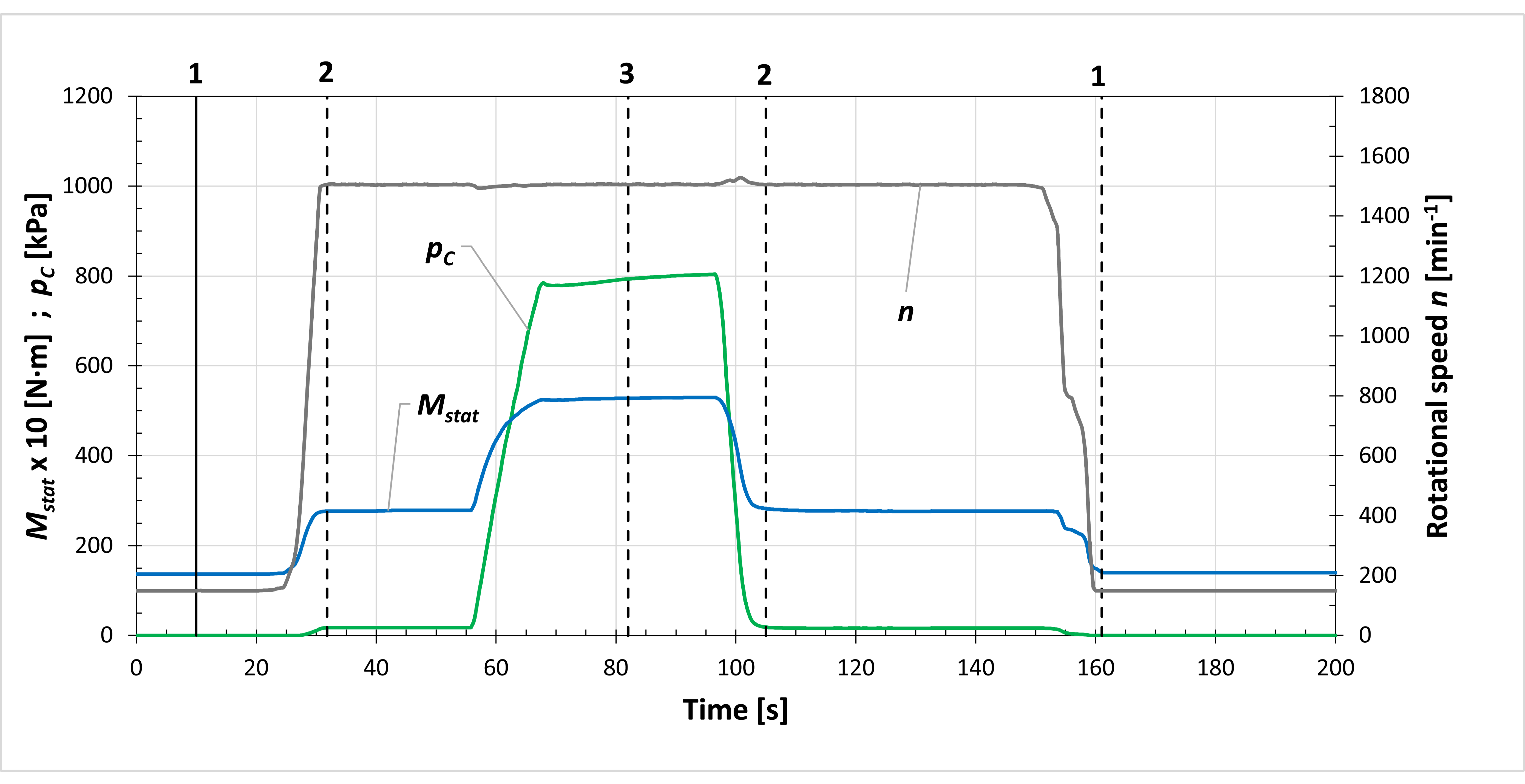
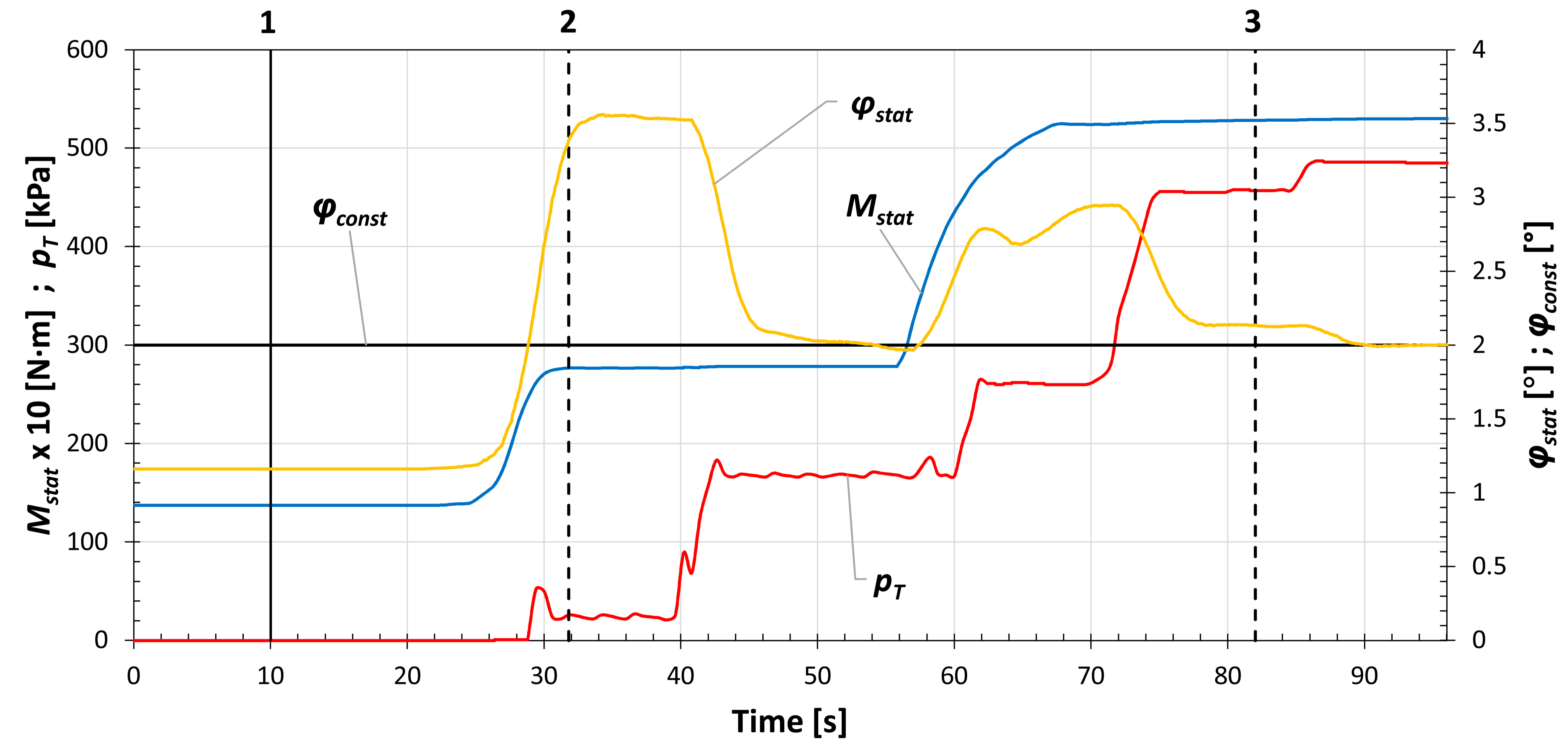
3. Results and Discussion

In this research, as the focus is placed on verifying the ability of our ECTACS to maintain a defined constant value φconst of the PTTO’s twist angle static component, and torsional vibration in the TOMS does not directly affect the process of twist angle control (is not present in the algorithm), only the static component Mstat of the load torque transmitted by the PTTO is shown in the presented results.
In Figure 8, the time courses of the static component of the load torque transmitted by the PTTO Mstat, compressor output air overpressure pC and rotational speed n of the TOMS during the experimental measurement are displayed. Three different operating modes (marked with numbers 1–3 in Figure 8) were chosen for testing:
(1)
Minimum rotational speed, negligible compressor output air overpressure (caused only by flow resistance in the compressor output piping);
(2)
Maximum rotational speed, negligible compressor output air overpressure (caused by flow resistance in the compressor output piping);
(3)
Maximum rotational speed, maximum compressor output air overpressure set by the throttling valve.
The vertical dashed lines in Figure 8 mark the times where the operating modes begin to be steady state (the rotational speed n and compressor output air overpressure pC do not change).
The sequence of mechanical system operating modes was chosen so that the mechanical system is initially minimally loaded (operating mode 1), then it is partially loaded (operating mode 2) and then it is fully loaded (operating mode 3). The sequence subsequently continues with the unloading of the mechanical system (operating modes 2 and 1).
The aim of our ECTACS is to keep the static component φstat = φconst regardless of the operating mode. Therefore, the φstat is the controlled variable. The manipulated variable is the overpressure pT in the compression space of the PTTO whose operating range was set to 0–800 kPa. Since the φstat is used directly as an input variable, it is a feedback control system. Since our system uses a very accurate mathematical and physical model of the PTTO for the computation of the needed value of pT, it also allows us to set the φstat very accurately (±0.1 degree without difficulty) during the operation of the mechanical system (Figure 9 and Figure 10).
In Figure 9, the control process by mechanical system loading is shown. The course of the φstat is very close to the defined constant value φconst (in our case φconst = 2°) of the PPTO’s twist angle static component after the change of operating mode 1 to operating mode 2 and subsequently operating mode 2 to operating mode 3. In the first case, the set point φconst ± 0.05° tolerance was reached in two steps of pT change, and in the second case in three steps of pT change (although it was very close after two steps of pT change).
There are certain idle intervals after the changes of the manipulated variable pT. The intervals are necessary in order to stabilize and measure the controlled variable correctly because transitional effects arise after the change of pT in the mechanical system. The needed stabilization time depends on the type, character and dynamical behavior of the mechanical system. The selection of a stabilization time for a specific mechanical system requires an individual approach based on theoretical or experimental investigation of the transitional effects caused especially by the rapid coupling pressure changes [38,39,40,41,42,43,44,45].
It is also important to notice that the control system reacts immediately to the change of the φstat, and it does not wait for the steady state. Since operation mode 1 is characterized by the minimum rotational speed and negligible compressor output air overpressure, the transmitted load torque is also the minimum and therefore unable to twist the PTTO to the desired φconst even by zero overpressure pT in the compression space of the PTTO.
In Figure 10, the control process by mechanical system unloading is shown. The course of the φstat is very close to the defined constant value φconst = 2° after the change of operational state 3 to operational state 2. The set point φconst ± 0.05° tolerance was reached in three steps of pT change (although it was very close again after two steps of pT change). Therefore, it is very important to select the set point tolerance reasonably (the wider the set point tolerance, the shorter the control process). From our existing research, e.g., [31,33,46,47,48,49,50,51,52,53,54], it can be said that the set point tolerance of 0.1° meets our requirements for practical applications of the PTTO with constant twist angle control. Again, regarding the change to operating mode 1, the transmitted load torque is the minimum and therefore it is unable to twist the PTTO to the desired constant twist angle φconst.
The customizable graphical user interface of the software of our ECTACS is shown in Figure 11.
The software is developed by us and it is programmed in C++. It allows us to set, via the graphical user interface, all needed parameters, for example, the φconst, tolerances, stabilization times, parameters of the PTTO’s mathematical and physical model, etc., even during the operation of the mechanical system. By monitoring the time courses of the selected parameters, the whole control process and the response of the mechanical system to the changes of the parameters or operating modes in real time can be observed. Furthermore, the data can be stored and viewed or exported for further analysis in post-processing mode.

4. Discussion

From the presented results, it is obvious that the proposed electronic constant twist angle control system meets the requirements for its function, namely that it can achieve, sufficiently accurately and quickly, the desired constant twist angle of the pneumatic tuner of torsional oscillations. It is possible to assume that the proposed system will increase the technical level of the equipment where it will be applied.
However, it is well known that every technical solution has advantages and disadvantages. The use of the presented electronic constant twist angle control system provides the following general advantages:
  • The system provides a quick and very accurate setting of a constant twist angle of the pneumatic tuner, thanks to the mathematical and physical model of the pneumatic tuner used for the twist angle computations;
  • Torsional vibration in the mechanical system does not directly affect the control device like in the case of regulators directly built into the pneumatic tuner;
  • Dynamic mass properties of the mechanical system are not influenced by additional masses because there are no regulators built into the pneumatic tuner;
  • It allows the use of any torsional oscillating mechanical system (regardless of size and transmitted load torque);
  • There is no friction between the sensors and the hubs of the pneumatic tuner;
  • It is possible to quickly replace the broken, damaged or malfunctioning sensor.
  • It is also necessary to mention the general disadvantages of the presented electronic system:
  • The function of the system is sensitive to dirt on the optical part of the optoelectronic sensors or the reflective black–white tape. This issue could be fixed using sensors with a similar working principle, for example, proximity probes and a toothed wheel instead of black and white stripes;
  • The system needs a power supply and in its present state and also a PC for the software part of the system;
  • The pneumatic tuner’s mathematical and physical model parameters, which need to be set in the software, have to be known.
In our further research, we are planning to verify the proper tuning of a torsional oscillating mechanical system with fan load characteristics using our electronic constant twist angle control system.

5. Patents

Homišin, J. Control system for continuous tuning of pneumatic coupling’s angular twist. Utility model SK7497Y1, Industrial Property Office of Slovak Republic, Banská Bystrica 2016. 1 August 2016. Available online: https://wbr.indprop.gov.sk/WebRegistre/Tlac/Download?fileName=COO.2161.100.7.3398451 (accessed on 18 September 2020). (In Slovak)
Homišin J. Continuously tuned mechanical system. Patent PL 216901 B1, The Patent Office of the Republic of Poland, Warszawa 24 October 2013. Available online: https://api-ewyszukiwarka.pue.uprp.gov.pl/api/collection/68227816fb32c5ac9046f508f5d65afa (accessed on 18 September 2020). (In Polish)

Author Contributions

Conceptualization, P.K. and M.U.; methodology, J.H.; software, R.G.; validation, M.U. and P.K.; formal analysis, J.H.; investigation, R.G., M.P. and J.K.; resources, M.P. and J.K.; data curation, M.U.; writing—original draft preparation, P.K. and M.U.; writing—review and editing, P.K., M.U. and M.P.; visualization, M.U.; supervision, J.H.; project administration, J.H.; funding acquisition, J.H. All authors have read and agreed to the published version of the manuscript.

Funding

Research was funded by grant project VEGA 1/0528/20 “Solution of new elements for mechanical system tuning.” “This work was supported by the Slovak Research and Development Agency under the Contract no. APVV-19-0328.”

Acknowledgments

The authors would like to thank Ing. Miroslav Bárány for the technical support.

Conflicts of Interest

The authors declare no conflict of interest.

References

  1. Zoul, V. Dynamic of propulsion, present situation and trends. Trans. Univ. Košice 2014, 2, 101–106. [Google Scholar]
  2. Czech, P. Application of probabilistic neural network and vibration signals for gasket under diesel engine head damage. Sci. J. Sil. Univ. Technol. Ser. Transp. 2013, 78, 39–45. [Google Scholar]
  3. Czech, P. Determination of the course of pressure in an internal combustion engine cylinder with the use of vibration effects and radial basis function—Preliminary research. In Communications in Computer and Information Science; Mikulski, J., Ed.; Springer: Berlin, Germany, 2012; Volume 329, pp. 175–182. [Google Scholar] [CrossRef]
  4. Puškár, M.; Bigoš, P. Output performance increase of two-stroke combustion engine with detonation combustion optimization. Strojarstvo 2010, 52, 577–587. [Google Scholar]
  5. Sinay, J.; Puškár, M.; Kopas, M. Reduction of the NOx emissions in vehicle diesel engine in order to fulfill future rules concerning emissions released into air. Sci. Total Environ. 2018, 624, 1421–1428. [Google Scholar] [CrossRef] [PubMed]
  6. Czech, P.; Wojnar, G.; Burdzik, R.; Konieczny, L.; Warczek, J. Application of the discrete wavelet transform and probabilistic neural networks in IC engine fault diagnostics. J. Vibroeng. 2014, 16, 1619–1639. [Google Scholar]
  7. Liang, X.; Shu, G.; Dong, L.; Wang, B.; Yang, K. Progress and Recent Trends in Torsional Vibration of Internal Combustion Engines. In Advances in Vibration Analysis Research; Ebrahimi, F., Ed.; InTech: Rijeka, Croatia, 2011; pp. 245–272. [Google Scholar] [CrossRef]
  8. Bartel, T.; Herold, S.; Infante, F.; Käsgen, J.; Matthias, M.; Millitzer, J.; Perfetto, S. Active Vibration Reduction of Ship Propulsion Systems. In Proceedings of the 2018 Joint Conference—Acoustics, Ustka, Poland, 11–14 September 2018; Marszal, J., Kochańska, I., Eds.; Polish Acoustical Society: Gdańsk, Poland, 2018; pp. 15–20. [Google Scholar] [CrossRef]
  9. Feese, T.; Hill, C. Prevention of Torsional Vibration Problems in Reciprocating Machinery. In Proceedings of the 38th Turbomachinery Symposium, Houston, Texas, 14–17 September 2009; Turbomachinery Laboratories, Texas A&M University: College Station, TX, USA, 2018; pp. 213–238. [Google Scholar] [CrossRef]
  10. Gurský, P. Identification of the Influence of Work Cycles on the Basic Properties of Different Types of Flexible Couplings and Their Mutual Comparison. Ph.D. Thesis, Technical University of Košice, Košice, Slovakia, 2011. (In Slovak). [Google Scholar]
  11. Han, H.S.; Lee, K.H.; Park, S.H. Parametric study to identify the cause of high torsional vibration of the propulsion shaft in the ship. Eng. Fail. Anal. 2016, 59, 334–346. [Google Scholar] [CrossRef]
  12. Han, H.; Lee, K.; Park, S. Evaluation of the increased stiffness for the elastic coupling under the dynamic loading conditions in a ship. Eng. Fail. Anal. 2016, 68, 254–262. [Google Scholar] [CrossRef]
  13. Homišin, J. New Types of Flexible Shaft Couplings: Development, Research, Application; Vienala: Košice, Slovakia, 2002. (In Slovak) [Google Scholar]
  14. Neupauerová, S. Investigation of stress allocation in the rubber-cord flexible element by FEF. Acta Mech. Slov. 2005, 9, 27–30. (In Slovak) [Google Scholar]
  15. Homišin, J. Contribution and perspectives of new flexible shaft coupling types—Pneumatic couplings. Sci. J. Sil. Univ. Technol. Ser. Transp. 2018, 99, 65–77. [Google Scholar] [CrossRef]
  16. Lubin, T.; Mezani, S.; Rezzoug, A. Experimental and theoretical analyses of axial magnetic coupling under steady-state and transient operations. IEEE Ind. Electron. Mag. 2014, 61, 4356–4365. [Google Scholar] [CrossRef] [Green Version]
  17. Sudano, A.; Accoto, D.; Zollo, D.; Guglielmelli, E. Design, Development and Scaling Analysis of a Variable Stiffnes Magnetic Torsion Spring. Int. J. Adv. Robot. Syst. 2013, 10, 1–11. [Google Scholar] [CrossRef]
  18. VanderBorght, B.; Albu-Schaeffer, A.; Bicchi, A.; Burdet, E.; Caldwell, D.; Carloni, R.; Catalano, M.G.; Eiberger, O.; Friedl, W.; Ganesh, G.; et al. Variable impedance actuators: A review. Robot. Auton. Syst. 2013, 61, 1601–1614. [Google Scholar] [CrossRef] [Green Version]
  19. Yang, T. The Principles and Structure of Variable-Inertia Flywheels. European Patent EP 0508790 (A1), 19 February 1997. Available online: https://patents.google.com/patent/EP0508790A1/zh (accessed on 18 September 2020).
  20. Lewis, O.G. Variable Inertia Liquid Flywheel. U.S. Patent 3248967, 3 May 1966. Available online: http://www.freepatentsonline.com/3248967.pdf (accessed on 18 September 2020).
  21. Walkowc, J. Active Torsional Vibration Damper. U.S. Patent 5678460A, 21 October 1997. [Google Scholar]
  22. Kadomukai, Y.; Yamakado, M.; Nakamura, Y. Torque Controlling Apparatus for Internal Combustion Engine. U.S. Patent 4922869, 8 May 1990. Available online: https://patents.google.com/patent/US4922869 (accessed on 18 September 2020).
  23. Vadamalu, R.S.; Beidl, C.; Hohenberg, G.; Muehlbauer, K. Active torsional vibration reduction: Potential analysis and controller development for a belt-driven 48 V system. Automot. Engine Technol. 2019, 4, 139–151. [Google Scholar] [CrossRef]
  24. Przybyłowicz, P.M. Torsional vibration control by active piezoelectric system. J. Theor. Appl. Mech. 1995, 33, 809–823. [Google Scholar]
  25. Hughes, A. Electric Motors and Drives: Fundamentals, Types and Applications, 3rd ed.; Elsevier: Oxford, UK, 2006. [Google Scholar]
  26. Homišin, J. Characteristics of pneumatic tuners of torsional oscillation as a result of patent activity. Acta Mech. Autom. 2016, 10, 316–323. [Google Scholar] [CrossRef] [Green Version]
  27. Homišin, J. Static optimisation of mechanical systems based on the method of extremal regulation. Sci. J. Sil. Univ. Technol. Ser. Transp. 2019, 103, 15–29. [Google Scholar] [CrossRef]
  28. Čopan, P. Application of new Tuning Method of Torsional Oscillating Mechanical Systems. Ph.D. Thesis, Technical University of Košice, Košice, Slovakia, 2014. (In Slovak). [Google Scholar]
  29. Pešík, L.; Skarolek, A.; Kohl, O. Vibration Isolation Pneumatic System with a Throttle Valve. In The Latest Methods of Construction Design; Dynybyl, V., Berka, O., Petr, K., Lopot, F., Dub, M., Eds.; Springer: Cham, Switzerland, 2016; pp. 75–79. [Google Scholar] [CrossRef]
  30. Kaššay, P.; Homišin, J.; Urbanský, M. Formulation of Mathematical and Physical Model of Pneumatic Flexible Shaft Couplings. Sci. J. Sil. Univ. Technol. Ser. Transp. 2012, 76, 25–30. [Google Scholar] [CrossRef]
  31. Homišin, J.; Kaššay, P.; Puškár, M.; Grega, R.; Krajňák, J.; Urbanský, M.; Moravič, M. Continuous tuning of ship propulsion system by means of pneumatic tuner of torsional oscillation. Int. J. Marit. Eng. 2016, 156, A231–A238. [Google Scholar] [CrossRef]
  32. Kaššay, P. Modeling, Analysis and Optimization of Torsional Oscillating Mechanical Systems. Ph.D Thesis, Technical University of Košice, Košice, Slovakia, 2014. (In Slovak). [Google Scholar]
  33. Homišin, J.; Kaššay, P. Optimal tuning method of ships system by means of pneumatic tuner of torsional oscillations. Acta Mech. Slov. 2009, 13, 38–47. [Google Scholar] [CrossRef] [Green Version]
  34. Homišin, J.; Urbanský, M. Partial results of extremal control of mobile mechanical system. Diagnostyka 2015, 16, 35–39. [Google Scholar]
  35. Urbanský, M.; Kaššay, P. The new realized mobile device for extremal control research and presentation. Sci. J. Sil. Univ. Technol. Ser. Transp. 2015, 89, 173–178. [Google Scholar] [CrossRef]
  36. DEWETRON Homepage. Available online: https://www.dewetron.com/products/components-and-sensors/rpm-angle-sensors/ (accessed on 17 July 2020).
  37. Zhang, P. Advanced Industrial Control Technology, 1st ed.; Elsevier: Oxford, UK, 2010. [Google Scholar]
  38. Urbanský, M.; Homišin, J.; Čopan, P. Examination of mechanical system response to gaseous media pressure changes in the pneumatic coupling. Sci. J. Sil. Univ. Technol. Ser. Transp. 2013, 81, 143–149. [Google Scholar]
  39. Uradnicek, J.; Kraus, P.; Musil, M.; Bachraty, M. Modeling of frictional stick slip effect leading to disc brake noise vibration and harshness. In Proceedings of the 23rd International Conference, Svratka, Czech Republic, 15–18 May 2017; pp. 1002–1005. [Google Scholar]
  40. Kraus, P.; Uradnicek, J.; Musil, M.; Bachraty, M.; Hulan, T. Thermo-Structural brake squeal fem analysis considering temperature dependent thermal expansion. Eng. Mech. 2018, 24, 429–432. [Google Scholar]
  41. Musil, M.; Suchal, A.; Uradnicek, J.; Kraus, P. The Complex eigenvalue analysis of brake squeal using finite element method. In Proceedings of the 22nd International Conference, Svratka, Czech Republic, 9–12 May 2016; pp. 406–409. [Google Scholar]
  42. Vinas, J.; Brezinova, J.; Guzanova, A. Tribological properties of selected ceramic coatings. J. Adhes. Sci. Technol. 2013. [Google Scholar] [CrossRef]
  43. Hudák, R.; Šarik, M.; Dadej, R.; Živčák, J.; Harachová, D. Material and Thermal Analysis of Laser Sinterted Products. Acta Mech. Autom. 2013, 7, 15–19. [Google Scholar] [CrossRef]
  44. Živčák, J.; Šarik, M.; Hudák, R. FEA Simulation of Thermal Processes during the Direct Metal Laser Sintering of Ti64 Titanium Powder. Measurement 2016, 94, 893–901. [Google Scholar] [CrossRef]
  45. Tlach, V.; Cisár, M.; Kuric, I.; Zajačko, I. Determination of the Industrial Robot Positioning Performance. Modern Technologies in Manufacturing. Available online: https://www.matec-conferences.org/articles/matecconf/abs/2017/51/matecconf_mtem2017_01004/matecconf_mtem2017_01004.html (accessed on 22 June 2020).
  46. Brezinova, J.; Guzanova, A. Friction Conditions during the Wear of Injection Mold Functional Parts in Contact with Polymer Composites. J. Reinf. Plast. Compos. 2010, 29, 1712–1726. [Google Scholar] [CrossRef]
  47. Toth, T.; Zivcak, J. A Comparison of the Outputs of 3D Scanners. Procedia Eng. 2014. [Google Scholar] [CrossRef] [Green Version]
  48. Kučera, P.; Píštěk, V. Testing of the Mechatronic Robotic System of the Differential Lock Control on a Truck. Int. J. Adv. Robot. Syst. 2017, 14, 1–7. [Google Scholar] [CrossRef] [Green Version]
  49. Kniewald, D.; Guzanova, A.; Brezinova, J. Utilization of Fractal analysis in strength prediction of adhesively-bonded joints. J. Adhes. Sci. Tech. 2008, 22, 1–13. [Google Scholar] [CrossRef]
  50. Kučera, P.; Píštěk, V.; Prokop, A.; Řehák, K. Measurement of the powertrain torque. In Proceedings of the Engineering Mechanics, Svratka, Czech Republic, 14–17 May 2018; pp. 449–452. [Google Scholar]
  51. Kuric, I. New Methods and Trends in Product Development and Planning. In Proceedings of the 1st International Conference on Quality and Innovation in Engineering and Management (QIEM), Cluj Napoca, Romania, 17–19 March 2011; pp. 453–456. [Google Scholar]
  52. Kučera, P.; Píštěk, V. Prototyping a System for Truck Differential Lock Control. Sensors 2019, 19, 3619. [Google Scholar] [CrossRef] [PubMed] [Green Version]
  53. Puškár, M.; Kopas, M.; Puškár, D.; Lumnitzer, J.; Faltinová, E. Method for reduction of the NOx emissions in marine auxiliary diesel engine using the fuel mixtures containing biodiesel using HCCI combustion. Mar. Pollut. Bull. 2018. [Google Scholar] [CrossRef] [PubMed]
  54. Jasminská, N.; Brestovič, T.; Puškár, M.; Grega, R.; Rajzinger, J.; Korba, J. Evaluation of hydrogen storage capacities on individual adsorbents. Measurement 2014. [Google Scholar] [CrossRef]
Figure 1. Pneumatic tuner of torsional oscillations type 4–2/70–T–C.
Jmse 08 00721 g001
Figure 2. Results of 4–2/70–T–C-type pneumatic tuner of torsional oscillations static measurements: (a) static load characteristics; (b) overpressure.
Jmse 08 00721 g002
Figure 3. Static parameters of 4–2/70–T–C-type pneumatic tuner of torsional oscillations: (a) rubber shell torque; (b) effective area of the coupling compression space.
Jmse 08 00721 g003
Figure 4. Interference diagram of a mechanical system with constant twist angle control.
Jmse 08 00721 g004
Figure 5. Experimental torsional oscillating mechanical system.
Jmse 08 00721 g005
Figure 6. Optoelectronic sensors Dewetron SE-TACHO-PROBE-01: (a) sensor attached to a data cable; (b) pair of sensors mounted in the experimental torsional oscillating mechanical system.
Jmse 08 00721 g006
Figure 7. Flowchart of constant twist angle control algorithm.
Jmse 08 00721 g007
Figure 8. Operating modes of the mechanical system used during testing.
Jmse 08 00721 g008
Figure 9. Control process by loading the mechanical system.
Jmse 08 00721 g009
Figure 10. Control process by unloading the mechanical system.
Jmse 08 00721 g010
Figure 11. The graphical user interface of the electronic constant twist angle control system.
Jmse 08 00721 g011

