Review

The Wave Energy Converter Design Process: Methods Applied in Industry and Shortcomings of Current Practices

1
Design Engineering Laboratory, Department of Mechanical, Industrial, and Manufacturing Engineering, College of Engineering, Oregon State University, 216 Rogers Hall, Corvallis, OR 97331, USA
2
Pacific Marine Energy Center, Corvallis, OR 97331, USA
*
Author to whom correspondence should be addressed.
J. Mar. Sci. Eng. 2020, 8(11), 932; https://doi.org/10.3390/jmse8110932
Submission received: 27 August 2020 / Revised: 27 October 2020 / Accepted: 9 November 2020 / Published: 17 November 2020

Abstract

:
Wave energy is among the many renewable energy technologies being researched and developed to address the increasing demand for low-emissions energy. The unique design challenges for wave energy converter design—integrating complex and uncertain technological, economic, and ecological systems, overcoming the structural challenges of ocean deployment, and dealing with complex system dynamics—have lead to a disjointed progression of research and development. There is no common design practice across the wave energy industry and there is no published synthesis of the practices that are used by developers. In this paper, we summarize the methods being employed in WEC design as well as promising methods that have yet to be applied. We contextualize these methods within an overarching design process. We present results from a survey of WEC developers to identify methods that are common in industry. From the review and survey results, we conclude that the most common methods of WEC design are iterative methods in which design parameters are defined, evaluated, and then changed based on evaluation results. This leaves a significant space for improvement of methods that help designers make better-informed decisions prior to sophisticated evaluation, and methods of using the evaluation results to make better design decisions during iteration. Despite the popularity of optimization methods in academic research, they are less common in industry development. We end this paper with a summary of the areas of WEC design in which the testing and development of new methods is necessary, and where more research is required to fully understand the influence of design decisions on WEC performance.

1. Introduction

The switch from fossil-fuel energy systems to renewable energy systems is one of the major avenues for addressing climate change [1]. As a near-zero emissions energy technology, wave energy has the potential to be a part of that change. Wave energy could provide electricity to the grid with more predictability than solar or wind energy [2], power off-grid off-shore operations such as aquaculture or ocean research [3], become an energy generator that is not bidding for large swaths of land, provide reactive power control with synchronous generators [4], and capture the large, dense energy source nearest to coasts where about 50 percent of the world’s population resides. In some regions, the seasonality of the wave energy resource corresponds to the seasonality of electricity demand [5]. Environmental impacts research thus far, though limited due to the lack of sea testing, indicates that local environmental degradation due to wave energy could be minimized through early incorporation of environmental studies and continued research [6]. These potential advantages of wave energy are what continue to motivate academic research and industry development of wave energy devices.
Currently, there are 4–8 WEC design archetypes (depending on categorization) and dozens of device designs within each category of archetype. Devices differ in the method of energy absorption, for example, oscillating body devices use the relative wave-induced motion of two device bodies whereas oscillating water column devices use the motion of air (induced by the motion of the water column) through a chamber. They also differ in the type of wave motion that is converted, be it heave, surge, or gravitational potential. Some devices are designed to be fixed to the seabed or a breakwater while others float and have moorings [7]. Devices intended for grid-scale energy production will likely become members of arrays of devices, which some researchers argue will require distinct developmental pathways [8]. The major areas for wave energy research and development include hydrodynamics, materials, controls, moorings, ocean installation and deployment, and electricity conversion and transport. Each of these research and development areas, combined with the relative youth of WEC deployment, makes the design space (the set of potential, complete design solutions) extremely large. With the recent surge of interest in off-grid WEC applications, i.e., [3], we can expect the design space to get even larger. Such a large design space demands organized design strategies to address the many challenges of WEC design.
There are three major programs in the area of marine renewable energy dedicated to organizing design and development strategies, two in the European Union and one in the United States. The DTOcean (first generation) and DTOceanPlus (second generation) projects, funded through the European Union’s Horizon 2020 program and partnering with academic, private, and government researchers internationally, aim to create open-access suites of design tools for the “selection, development, and deployment of ocean energy systems” [9]. The software tools are available on GitHub, and descriptions of the alpha versions of the tools can be found in the publications section of the program’s website. The tools range from tools for structured conceptual innovation to tools for logistics planning and were released in May of 2020, too recently for us to discuss their adoption in this paper [9]. Nonetheless, we include details about some of the DTOceanPlus tools throughout this review. MaRINET (Marine Renewables Infrastructure Network) (first generation) and MaRINET2 (second generation) are also projects funded by the European Horizon 2020 program. They focus on the standardization of physical modeling and device testing procedures. They help to facilitate access to testing facilities and the training and dissemination of information necessary for productive, successful testing [10]. The WaveSPARC (Systematic Process and Analysis for Reaching Commercialization) project includes researchers from the United States Department of Energy National Renewable Energy Laboratory and Sandia National Laboratories working toward delivering “the necessary methods and tools to enable new, groundbreaking wave energy technology” [11]. Their work includes systems engineering analysis, concept development, and performance assessment [11]. These three federal-level programs are indicative of the need for increased structure in the design and development of wave energy systems. In this paper we bring together academic literature, reports from these federal programs, and survey responses from WEC designers and developers to comprehensively review the practices of WEC design. Our intention is to provide a review not of the field generally as previous reviewers have done, i.e., [4,12,13] but of the methodologies for design and development being researched and used. We aim to expose to researchers specific areas of need for structured design tools. Although there are many academic publications which describe WEC design methodologies employed in research, there is no work which synthesizes the design methods and tools used by WEC developers throughout the design of a single device.
In Section 2 of this paper, we review the WEC design problem by discussing the societal need for wave energy development, the specific challenges the industry faces, the requirements of a WEC, and the metrics for success. In Section 3, we review the process of WEC design throughout project definition, conceptual design, embodiment design, and detail design. In Section 4, we outline the design and evaluation methods employed in WEC design (and more broadly) to achieve 11 specific design requirements. In Section 5, we discuss the development and results of a survey distributed to WEC designers and developers regarding the methods they use in WEC design. The survey results allow us to connect and compare the WEC design methods present in the literature with those being put to use in industry, providing insight that would otherwise be lacking in a literature review due to the fact that developers do not commonly publish their methodologies. To conclude, we (1) identify the design approaches and tools that are most widely used in practical WEC design, (2) identify areas where promising tools or methodologies already exist but are not widely applied, (3) identify the areas where designers are most in need of new tools and methodologies, and (4) identify areas where designers need a better understanding of the effect of design decisions on WEC performance. We also intend for this paper to be particularly useful for researchers or developers who wish to better understand how their work fits in to the greater field of WEC design.

2. Generalized Definition of a WEC Design Project

The first steps in a design project are to identify the needs to be addressed, clarify the problem, define the requirements of the system and the necessary functions, and decided on metrics for measuring successful performance [14]. These steps have been taken on at the scale of the entire industry by various wave energy researchers, through research such as stakeholder analyses, wave resource assessment, and other projects which we will discuss in this section. Industry-wide, generalized project definition can be helpful to designers when defining their individual project, but should not entirely replace the project definition stage of the individual project (discussed in Section 3.1).

2.1. Identify the Need and Clarify the Problem

For grid-scale WEC design, wave energy researchers have identified the societal need for near-zero-emissions energy sources given the present and future consequences of climate change caused by greenhouse gas emissions [15]. To better understand how wave energy might be able to satisfy this need, researchers have made estimates of total potential electricity production and done wave resource assessment which can help developers and governments choose the best locations for WEC farms. The potential electricity which could be generated by ocean renewable energy technology (wave, tidal, current, and salinity gradient combined) was estimated by Sims et al. to be 500 GW capacity globally [16] and the global energy potential as 20 EJ/yr by Krewitt et al. [17]. These estimates consider energy resource and technical potential, but not social, political, or economic factors. Wave energy-specific resource assessments dealing with quantifying total resource and have been done globally (estimating a global gross resource of 3.7TW [18], 2.11TW [19]), as well as for many specific regions such as the Pacific Northwest of the United States [2], the continent of Australia [20], the Mediterranean [21], the Atlantic coast of Europe [22], and many more. These regional assessments can further inform designers by quantifying the dominant wave frequencies, seasonality, water depth, distance from shore, and directionality of the wave resource. From these resource assessments, the functional design challenges of converting wave resource into usable energy emerge.
To further help clarify the design problem, economic studies have identified some of the most pressing areas for improvement of WEC design in order to drive down the cost of energy. Studies suggest that researchers and developers must increase the amount of energy that a WEC systems can produce annually [23] and prove the long-term reliability of that energy production [24]. They also recommend that WEC designers must improve the mooring systems, control strategies, and power take-off (PTO) efficiency of WECs. Collectively, economic studies show that designers must learn to prototype with low-cost materials and improve modeling verification. They acknowledge that lack of deployment and testing experience has led to the need to improve installation practices, make more accurate cost estimates, gain public acceptance, and better understand environmental effects [23,24,25,26].
Identifying other societal needs besides that for low-emission electricity has led researchers to suggest the application of wave energy in emerging markets such as desalination or sustained ocean observation [3,27]. Research and development of WECs designed for off-grid markets has the potential to allow for the smaller deployments that give developers the experience necessary to address the aforementioned installation, cost, and uncertainty-related challenges [3,27]. If developers can break into smaller markets, they may be able to secure some of their own income and learn lessons which will drive future innovation. The hope is that off-grid deployments can help to break what some call the “wave energy paradox” in which lack of investment and support, lack of deployed devices, and lack of commercial returns combine to paralyze innovation [28]. Researchers have further diversified the potential applications of wave energy through studies on remote communities where the cost of energy is already high i.e., [29] and through co-location studies which explore the potential of combined energy generation with offshore wind to reduce structural, installation, and maintenance costs, i.e., [30]. The diversity of need and potential application of wave energy explored in research serves as a baseline for WEC designers as they clarify the specific design problem which they will address.

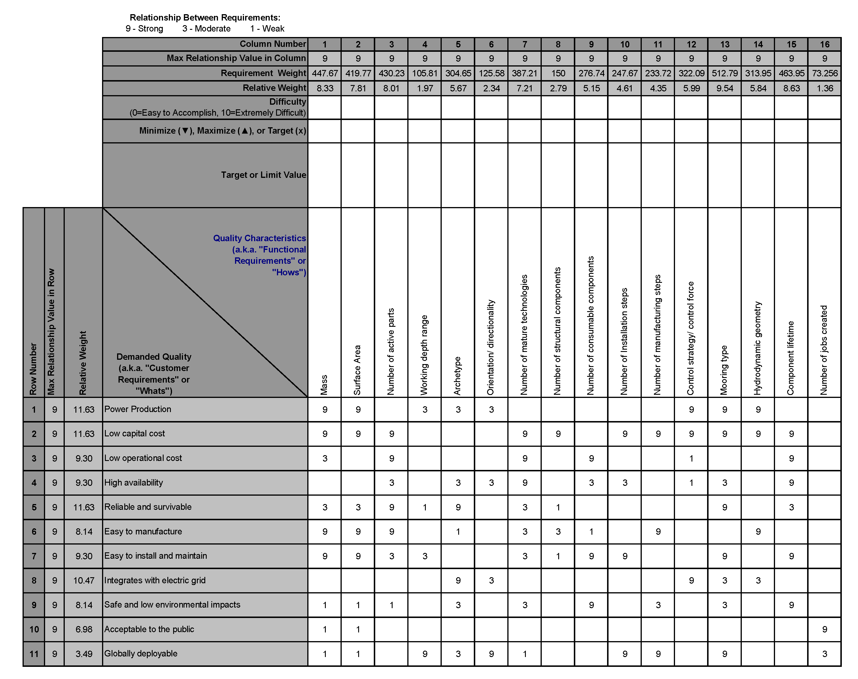
2.2. Define Requirements and Functions

The customers for a WEC project include the electricity end-users, utilities, local, state, and federal governments and permitting organizations, potential projects developers, system operators, manufacturers, and local communities near the wave energy site. Figure 1, created by Babarit et al. shows the many stakeholders involved in a WEC design project, their relative importance, and the part of the process in which they are involved [31]. Having identified the stakeholders for a wave energy project, Babarit et al. go on to outline the explicit needs of those groups using a systems engineering approach [31]. They identify seven first-tier stakeholder requirements: have a market competitive cost, provide a secure investment opportunity, be reliable for grid operations, benefit society, be acceptable for permitting and certification, be safe, and be globally deployable. They then translate those needs into a taxonomy of functional requirements for wave energy converters, the highest level of which includes generate and deliver electricity from wave power, control farm and subsystems, maintain structural and operational integrity of farm and subsystems, provide suitable access and transportation, and provide synergistic benefits [32]. From the first functional requirement’s sub-requirements, we can identify the common subsystems of a WEC—subsystem that collects wave power (the WEC), that convert wave power (the PTO), that transports power, that controls the physical position (mooring/foundation), and that controls the internal dynamics (controls) [32]. Research done by Ruiz-minguela et al. determines a similar set of stakeholders and stakeholder requirements, categorizing stakeholders into either financiers, condition setters, developers, and energy users. For grid-scale WEC development, they note that the project developers are the most important stakeholders, followed by the financiers and conditions setters, and energy users as the least important. They use a matrix-based approach adapted from axiomatic design (discussed in the following section) to translate stakeholder requirements onto functions, subsystems, and components [33].

2.3. Metrics of Success

One of the primary performance measures for energy generating technologies is the Levelized Cost of Energy (LCOE). LCOE is the total annual cost of a technology, including all capital and operational costs, normalized by the annual energy production of a device, measured in $/kWh. In the case of wave energy, both the costs and annual energy production are estimates with levels of uncertainty corresponding to the maturity of the technology [25]; in the case of WECs, the uncertainty is quite high. Researchers and developers have created models to estimate the LCOE of different wave energy devices, e.g., [23,25,34,35,36]. For wave energy and other devices with high uncertainty due to lack of maturity, LCOE is not the best indicator of economic performance or commercial readiness [24,37]. Researchers and organizations have come up with a few other metrics to use to quantify performance and benchmark WECs between one another. Babarit et al. use absorbed energy per characteristic mass [kWh/kg], absorbed energy per characteristic surface area [MWh/m 2 ], and absorbed energy per root mean square of PTO force [kWh/N] [38]. Each of these quantities relates energy production from numerical models to a cost-related metric that can be quantified with significantly less uncertainty than, for example, lifetime operational costs. Another study by Babarit compares WECs of different archetypes based on their capture width ratio (CWR) which is the ratio of the capture width, defined as the absorbed power over the wave power per meter wave crest, to the characteristic length of the device [7]. This metric accounts for hydrodynamic performance, but no cost drivers, as does the commonly-used mean annual energy production (MAEP) metric. Estimating MAEP requires power matrices from time domain simulations and site-specific wave data. Hiles et al. estimate that between the uncertainties in the simulations and those in the wave data, estimates of MAEP have an uncertainty of 2–20% [39]. Economically-focused metrics include the net present value (NPV), internal rate of returns (IRR) and payback period (PBP). Guanche et al. show a method for statistically estimating these metrics and understanding their variability due to changing wave conditions [40]. A paper by Caio et al. summarizes the use of these and similar metrics by various organizations, emphasizing the lack of convergence on a standard performance measure [28].
In the U.S. Department of Energy’s Wave Energy Prize, the judges used some of the metrics discussed above, along with a metric of capture width per characteristic capital expenditure (ACE) and a metric of hydrodynamic performance quality (HPQ). HPQ used the ACE metric along with multipliers based on mooring loads, station keeping, peak to average absorbed power, PTO behavior, absorbed power in realistic seas, and control effort expended [37]. The multipliers accounted for other important performance requirements beyond cost and energy production, such as reliability and grid compatibility. In a further effort to account for important factors in WEC design and create an industry-standard assessment of performance, especially for devices of low Technology Readiness Level (TRL) and thereby high uncertainty, researchers at the National Renewable Energy Lab and Sandia National Labs have created a techno-economic performance assessment called the Technology Performance Level (TPL) Assessment [32]. The TPL assessment quantifies performance through a question-by-question assessment performed by experts in the field with information provided by designers. Rather than a single metric which can be calculated to varying levels of uncertainty depending on the modeling and testing which has been done for a device, TPL includes qualitative and quantitative performance measures under which device properties are estimated within high-medium-low ranges. Though TPL could become a comprehensive measure of performance, it cannot be used in device design optimization, while other metrics can.

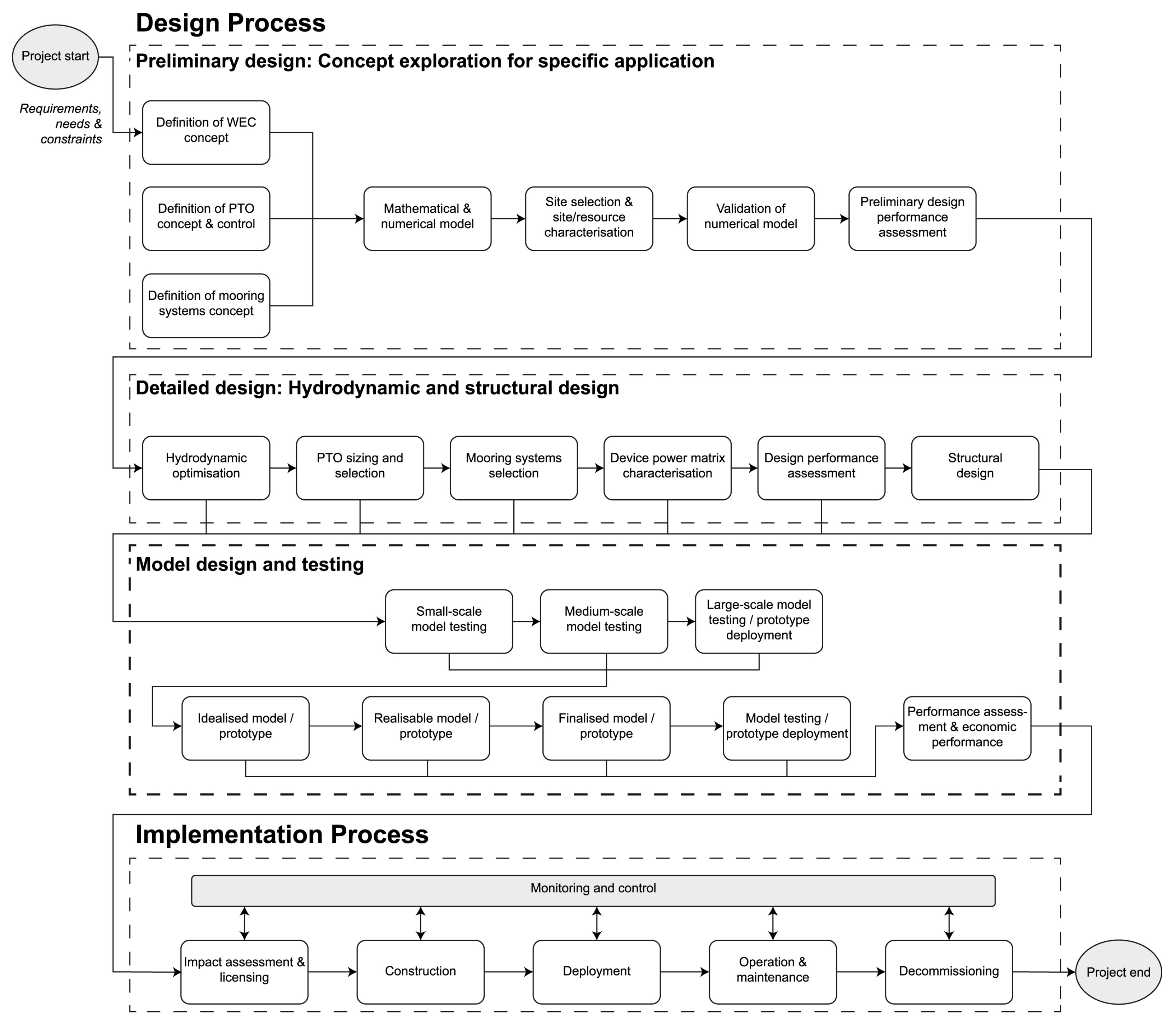
3. Stages of a WEC Design Process

Throughout the literature, there are many methods presented for specific aspects of WEC design, especially numerical modeling and optimization. Yet, as Henriques et al. point out, “in general, it has been observed that information and knowledge have been presented dispersed and without integration […] but no global overviews have been reported in a systematic and comprehensive way” [41]. Portillo et al. present the overview of the life cycle of a wave energy project, shown in Figure 2.
The overview provided by Portillo et al. is not intended as a detailed process for designers to follow, yet examining the gaps in the process they outline can help us begin to understand where we can improve and adjust WEC design practices. The process shown in Figure 2 begins with the definition of the WEC and the PTO concept during preliminary design, after which designers create and validate a numerical model and gather data about a selected site. For a general design project, 50–80% of the cost is committed during conceptual design [42,43], the part of the design process leading up to concept definition; yet the process shown in Figure 2 does not show any steps leading up to concept definition. This reflects the tendency of WEC designers to under-utilize or even forgo the conceptual design process (shown in Section 3.2 and Section 5.2.1) which could be due to lack of experience with conceptual design processes, or to shortcomings of those processes for application in WEC design. The first performance assessment shown in Figure 2 does not occur until after model validation, indicating that designers might not evaluate concept variants before spending the time and money necessary to create and validate models. Conceptual design steps in the WEC design process need to include early evaluation of concepts prior to spending significant amounts of time and money defining a single concept because failed concept selection will lead to higher development costs and longer development times later in the design process [44]. In Figure 2, following the preliminary performance assessment based on numerical models, designers may have to circle back to concept definition (iteration is not shown for image clarity). As we will see in the following sections, modeling and simulation processes have been well detailed in literature, but the steps that designers should take to make the next iteration better than the last once they have simulation results are missing from Figure 2 as well as from the literature more generally.
Following Figure 2, once preliminary design is complete, designers work through detail design which includes hydrodynamic optimization, PTO sizing and selection, mooring systems selection, and another performance assessment followed by structural design. Designers may return to concept selection should the results of the second performance assessment be unfavorable. Following detailed design, designers move on to physical model design and testing, where they incur significant costs, then implementation, for which there are few examples for WECs, i.e., [46]. Weber et al. have discussed the importance of not entering the testing stages too early, or with a WEC that cannot meet the design requirements [47]. Avoiding such pitfalls requires design techniques which will help designers ideate better WEC concepts from the start. These techniques will likely need to extend beyond the modeling and optimization techniques which are currently central to WEC design. Design theorist Nam p. Suh points out that design techniques based on modeling and optimization “do not provide tools for coming up with a rational system design beginning from the definition of the design goals” [48]. The need for WEC design methodologies and tools which emphasize the early stages of the design process has been identified by several design researchers [47,49,50]. In the following sections, we discuss methods at four stages (project definition and management, conceptual design, embodiment design, and detail design) which may help to fill some of the gaps in the WEC design processes illustrated by Figure 2, systematically address the challenges discussed in the previous section, and improve the overall trajectory of WEC design.

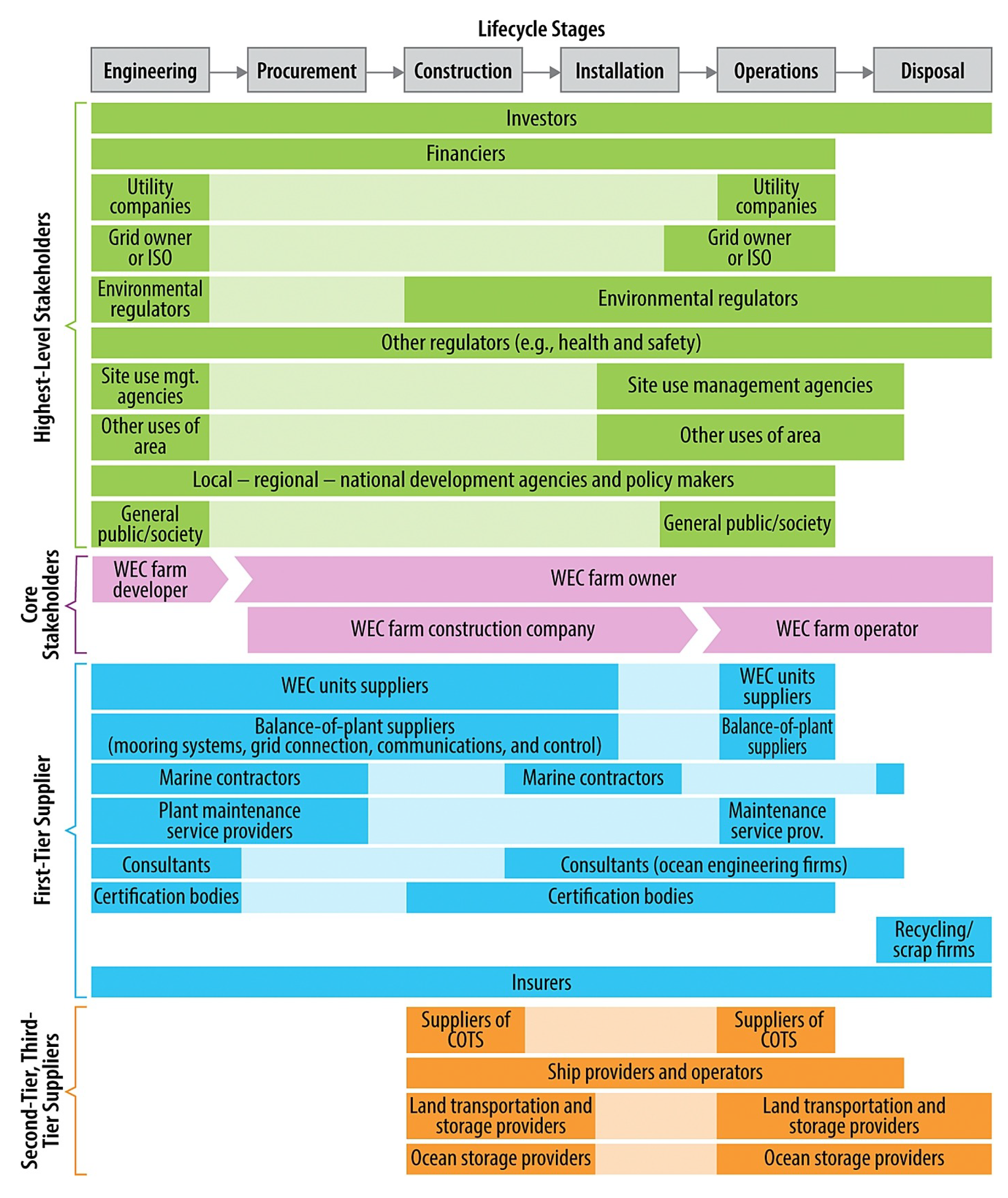
3.1. Project and Product Definition

The project and product definition stages of the WEC design process should include identifying need, clarifying the problem, defining requirements and functions, and determining metrics for success [14], as mentioned in Section 2. Designers or supervisors might also determine a design philosophy which they intend to use to guide the rest of the project. The need for near-zero-emissions energy technology has been largely accepted by the wave energy industry and research fields, and for that reason, techniques for need finding have not become an essential piece of the WEC design process, even as interest in alternative markets grows. Nevertheless, need finding remains an important for enabling individual projects to achieve their intended end use and to be accepted by users and the community. This fact is exemplified by the ever-growing body of research in the areas of user-centered design, human-centered design, participatory design, codesign, and design justice in which community and user needs are centralized in the design process [51]. Typical techniques for need finding include interviewing, surveying, or observing customers [14], while more cross-cutting techniques focus on involving potential customers throughout the design process [52]. Early stakeholder meetings with manufacturers, utilities, or even potential end users are forms of need finding used in the wave energy industry. Successful need finding will enable designers to identify explicit needs of the customers, implicit needs, and niche needs. The requirements outlined by Barbarit et al. [31] and discussed in Section 2.2 can be considered explicit needs. Implicit needs, needs which customers may not be able to recognize or articulate, and niche needs, those which are specific to a discrete customer population but present a unique market potential, are often project-specific. Greater participation in need finding could lead to new pathways for wave energy. Designers may use templates such as those provided by David Ullman in Modern Product Design to make need finding more productive and to derive an adequate problem statement from the work [14].
Quality Function Deployment (QFD) and functional modeling are methods for dealing with customer and functional requirements. QFD includes defining and weighting customer requirements, relating those requirements to measurable engineering specifications, benchmarking competitors against those customer requirements, and determining the relationship between engineering specifications [14]. QFD can help designers determine what the most important specifications of the WEC are and what potential trade-offs exist between and among engineering specifications and customer requirements. The visualization for QFD is called a House of Quality (HoQ). We have included an example of the central section of the HoQ in Figure 3. In this section of the HoQ, the designer identifies how each design specification relates to each customer requirement (1 representing a weak relationship, 3 moderate, and 9 strong). Given the designer-input weights of the customer requirements and the relationships between requirements and specifications, the HoQ calculates the relative weight of each design specification (fourth row from top). The weights can be used to focus design efforts throughout the process. A complete HoQ requires designers to input target values for design specifications, something that designers might not otherwise do this early in the design process. The weights and relationships input into the HoQ may be changed as the designer learns about the system. The Structured Innovation design tool from DTOceanPlus includes QFD for use in ocean energy applications [50], and the method was employed by Ruiz-Minguela et al. in their 2019 publication [33].
Functional modeling, or functional decomposition, helps designers answer the question, what must the product do? Designers begin the model with the primary function, then decompose that function into sub-functions (boxes) and operating flows (arrows) [53]. When creating a functional model, the designer does not specify components, instead, specifies abstract functions. A functional model can be used for the stages of a WEC’s lifetime in which there are human–WEC interactions (suhc, helping designers identify where human interaction is necessary and potential human-caused errors [54]. An example of a high-level functional model for a WEC intended for autonomous underwater vehicle (AUV) recharge is shown in Figure 4.
Design philosophies are overarching approaches to design. Those which have good potential to guide WEC design include Systems Engineering, Set-Based Design, Axiomatic Design, and principles of Ecological Engineering. It is also likely that user-centered and participatory design approaches will prove valuable for emerging market WEC devices for which the end user has more direct contact with the device, such as devices designed for AUV recharge.
  • Systems Engineering is a more traditional engineering practice than those mentioned above. Systems Engineering and standard product design methods guide designers through similar initial design steps of determining a mission, identifying stakeholders and stakeholder needs, identifying the functional requirements to satisfy those needs, and using the relationship between the stakeholder needs and the functional requirements to set targets for the functional requirements. Bull et al. applied the Systems Engineering approach to a wave energy farm to propose taxonomies for WEC capabilities (sometimes called stakeholder needs or customer requirements) and WEC functional requirements [32]. Systems Engineering encourages designers to consider the whole life cycle of the WEC and to decompose the WEC into rational subsystems.
  • Set-Based Design is a design methodology which encourages designers to develop multiple concepts concurrently. Instead of choosing the best concept variant with the limited knowledge intrinsic of the conceptual design stages, Set-Based Design focuses on eliminating inferior concepts while iteratively defining and developing the other concepts in order to avoid choosing a concept based on imprecise data [55]. The methodology encourages designers to update their problem statement as they learn more about the problem. Set-Based Design has been acknowledged as particularly useful for design problems with high degrees of uncertainty [56], such as WEC design [49]. Delaying commitment to a single concept has shown to decrease the time and money spent throughout the design process [57]. Set-Based Design could help WEC designers follow the TPL-TRL curve suggested by Weber as a pathway toward successful commercialization [47] by integrating performance assessment prior to concept selection and refocusing WEC design toward performance rather than exclusively readiness.
  • Axiomatic Design is a design theory for general systems, including non-physical systems, which uses a rigorous decision-making framework to guide designers toward rational designs of reduced complexity. Axiomatic Design theory is based on the theorem that the best design is the one in which all functional requirements are independent (Axiom I) and the information content is minimized (Axiom II). System architecture is defined using matrices and flow diagrams [48]. Proponents of Axiomatic Design claim that it reduces technical and business risk compared to heuristic design methods. Axiomatic Design was integrated into an early design stage of marine energy design by Ruiz-Minguela et al. and determined to help determine risk factors, focus designers on key properties of the system, and compare concept alternative [33]. The theoretical definition of a successful system in Axiomatic Design could help WEC designers assess their WECs with less uncertainty and its rigorous process for decision making could guide WEC designers toward better designs before they conduct detailed hydrodynamic modeling and testing campaigns. Non-physical requirements of WECs, such as community and government acceptability, may be more challenging, but by no means impossible to integrate into Axiomatic Design.
  • Principles of Ecological Engineering provide guidance for the design of systems which are integrated into the natural environment. Typically, Ecological Engineering processes are applied to projects at the junction of ecology and engineering such as wetland restoration or or sustainable timber harvest [58], but Bergen et al. assert that the principles of Ecological Engineering can be applied to any engineered system which extracts natural resources [59]. This would include WECs harvesting energy from ocean waves. The principles of Ecological Engineering include the two design axioms from Axiomatic Design as well as “design consistent with ecological principles”, “design for site-specific context”, and “acknowledge the values and purposes that motivate design” [59]. The principles of Ecological Engineering could help WEC designers improve the resilience of WEC systems, better account for upstream and downstream effects, utilize natural ecological functions, and integrate their primary purpose throughout the design process. Ecological engineering practice may also lead to unique WEC concepts through its emphasis on functional diversity, site-specific solutions, and human values.

3.2. Conceptual Design

Once designers have defined the goals of the project and the requirements of the WEC, they are ready to ideate WEC concepts. A concept is “an idea that is sufficiently developed to evaluate the physical principles that govern its behavior” [14]. The conceptual design process can be broken up into concept generation and concept evaluation. Overall, the employment of structured conceptual design methods has been limited in WEC development as well as WEC research [50]. There are few publications that detail the conceptual design of a WEC. Those that do display a similar approach to one another: identify the most pressing challenges in WEC design, then select an existing WEC archetype and present 1–3 design ideas to address those challenges. Some examples of such an approach are shown in a publication detailing the design of the SEAREV WEC [60], another describing a WEC designed for hydrogen production [61], and another on the Inertial Sea Wave Energy Converter (ISWEC) [62]. For the SEAREV WEC, the designers considered survivability, maintenance, and performance as the most pressing challenges and chose to address those challenges with a fully-enclosed rotating-mass WEC with latching control. They avoided end stops and emerging superstructures [63]. Boscaino et al. focus the design of their WEC for hydrogen production on reliability [61]. Bracco et al. choose the ISWEC to address the challenge of reliability and survivability by enclosing all components of the WEC into one seawater-tight floating body as well [62]. The piece-wise innovation exhibited by these design decisions which focus on a single primary challenge does not cover the breadth of challenges that WEC designers must overcome. This type of design is commonly known as spiral design or point design. Point design typically requires many iterations and leads to feasible, but not necessarily optimal concepts [55]. Structured concept generation and evaluation methods may be able to help designers ideate high performing concepts which address the full scope of challenges in WEC design.

3.2.1. Concept Generation

Methods of concept generation are typically categorized as creative methods or rational methods. Creative methods include brainstorming, sketching, and mind mapping. Some general rules of creative processes are that all judgment/evaluation should be avoided until the end of the process and all ideas should be recorded. Concepts may be generated verbally or on paper, by individuals or by groups. Varying group size and time limits and preventing fixation on a single idea are important aspects of the creative concept generation process [14]. Rational concept generation methods include the theory of inventive problem solving (TRIZ), biomimicry, and morphological matrices. The application of TRIZ in WEC design has been discussed in detail by Costello et al. [64] and has been integrated into the Structured Innovation design tool by DTOceanPlus [50]. On the website triz40.com, designers can use an online matrix to work through TRIZ [65]. Methods of biomimetic design have been applied to wave energy as well, i.e., [66,67]. There have not been publications on morphological techniques applied to WECs, but So et al. show an example of a morphological matrix for the mechanical to electrical power train in their publication on PTO-Sim, a library for WEC-Sim which models different PTO elements [68]. In a morphological matrix, each row is a subfunction, and each cell in that row is a different concept for carrying out the subfunction. Designers create concept variants by combining a single concept from each row. Morphological techniques have received attention as the basis for computational conceptual design [69]. It has been shown that design teams that generate many concepts early in the design process are more efficient in terms of cost and time, overall [70].
Conceptual design is not limited to the definition of high-level WEC characteristics. The strategies can be used to design subsystems and components as well. Storyboarding is a conceptual design method common in the film and animation industry, but has been researched and used in engineering fields as well [71]. In engineering design, storyboarding is an effective way to “demonstrate system interfaces and contexts of use” by creating graphical narratives [71]. Throughout Section 4 of this paper, we mention potential uses of storyboarding for developing WEC survival strategies, manufacturing plans, and installation and maintenance outlines. Manufacturing, installation, and maintenance are all aspects of WEC design that exemplify the human-WEC interface while creating survival strategies are preparing the WEC system for changing contexts of use. Truong et al., provide details on how to perform storyboarding.
The methods of hierarchical decomposition can guide designers in the continual use of conceptual design methodologies. Hierarchical decomposition is a process in which designers decompose the system from the highest level systems into subsystems, sub-subsystems, and so forth, down to individual components [72]. Ruiz-Minguela et al., present a system hierarchy for a grid-scale WEC [33]. Designers may begin by defining the highest-level concepts, then work down, using decisions from the higher-level as constraints on conceptual design of lower-level systems. Hierarchical system’s design beginning at the highest-level is “usually acceptable when the system design and architecture are mature and the new design is not fundamentally different from experience. However, for cases where it is permissible and, in fact, desirable to explore completely new architectures, it can often be unclear how the hierarchy of the design parameters should be set” [72]. Guindon’s research on software systems reached a similar conclusion that “a top-down decomposition appears to be a special case for well structured problems when the designer already knows the correct decomposition” [73]. We argue that WEC design is an area where completely new architectures are desirable due to the fact that none of the current concepts has proven to be ideal. The alternative to the top-down approach would be a co-design approach in which multiple subsystems are designed concurrently beginning in the conceptual design stages. Multi-subsystem co-design [74] has received attention in the wave energy control design and optimization fields, i.e., [75,76]. Co-design could be an effective approach for WEC design given the strong impacts of design decisions made for one subsystem on another subsystem (and vice versa), such as the impacts of device geometry on optimal control strategy [77,78] or of array layout on control strategy [79]. Implementing co-design practices from the conceptual design stages, or even simply restructuring the typical hierarchy could allow designers to take advantage of the interactions between subsystems to come up with novel WEC concepts. The Design Structure Matrix (DSM) is a tool that can be used to distinguish the relationships between subsystems/components during the early design stages and can help designers determine a hierarchy for design. Like for TRIZ, there is an online tool for DSM as well [80].

3.2.2. Concept Evaluation

Methods of concept evaluation include decision matrices, concept screening, utility analysis, Pugh methods, and strengths, weaknesses, opportunities, threats (SWOT) analysis. The overarching design approach implemented by a design team will impacts how concept evaluation methods are used, for example, a design team using Set-Based Design might choose to input ranges of values into decision matrices when there is uncertainty and only eliminate a concept from consideration when it is dominated by another concept (its highest score is lower than another concept’s lowest) as described by Malak et al. [81]. Alternatively, a team following axiomatic design may evaluate concepts in reference to how well they satisfy the two design axioms. Design teams often allot a specific amount of time to the conceptual design stages, and choose a concept at the end of that time regardless of the uncertainty that remains [55]. Some industries have industry-specific conceptual design techniques. For example, chemical engineering process design researchers have presented a hierarchical conceptual design process [82], and sustainable product designer researchers have presented a tool called the “GREEn Quiz” to improve the understanding of design trade-offs during the early design phases [83]. WEC designers might benefit from WEC-specific conceptual design techniques. Our research group is currently testing a tool similar to the GREEn Quiz for use in emerging market WEC conceptual design. Bubbar et al. offer a WEC-specific concept evaluation method based on Falnes’ method of turning the linear power optimization problem into an analytical problem which can be solved using mechanical circuit representations. Designers may solve the analytical problem by matching the impedance of the WEC to that of the PTO to determine a maximum power capture [84]. This theory could allow researchers to compare the maximum theoretical power of a WEC architecture (which they define as “the set of configurations, which share the same device topology” [84]) to that of other WEC architectures. The method offers an alternative to detailed modeling and simulation for evaluation of power production in the conceptual design stages. Designers can compare their device’s power output to that theoretical maximum [84].

3.3. Embodiment Design

Embodiment design is the stage where designers identify critical specifications, generate overall layouts, detail subsystems, and build models and prototypes. It is the stage of the design process focused on iteration and feedback [14]. The work of conceptual and embodiment design often overlaps, especially if designers are working on multiple concepts. Many of the design methods and tools which we discuss in Section 4 are a part of the embodiment design stages, but in this section, we will focus on numerical modeling and prototyping, as these are two of the central aspects of WEC embodiment design.

3.3.1. Numerical Modeling

Tools for numerical modeling of wave energy devices include hydrodynamic solvers, dynamic analysis software, and simulation tools. These tools help designers determine localized WEC effects, work toward control design, and calculate annual energy production, among other quantities [85]. The hydrodynamic solvers simulate a WEC’s response to wave action. Many WEC researchers and developers use boundary element method (BEM) solvers [85], which use linear potential flow theory to estimate wave–body interactions. Though linear potential flow theory has limitations in terms of the fidelity of results, it is common in early stages of WEC development because of its quick computational speed compared to nonlinear simulation methods such as computational fluid dynamics (CFD) or smoothed-particle hydrodynamics (SPH) [86]. A study comparing linear, weakly nonlinear, and fully nonlinear modeling techniques determined that for small to medium wave conditions, linear models give results close to those of nonlinear models and should be used in those scenarios due to their computational efficiency [87].
Common BEM software tools used in wave energy include Ansys Aqwa, WAMIT, and NEMOH. Of the three, NEMOH is the only open source software. When Penalba et al. compare NEMOH to WAMIT, they identify a lack of manual and test cases as “a significant weakness of NEMOH” [86], but this issue has recently been addressed by Ancellin et al. in their introduction of Capytaine, a Python-based linear potential flow solver which is meant to be easier to maintain and develop [88]. Each of these BEM solvers simulates in the frequency domain, meaning that if a designer wants to simulate the WEC in the time domain (which is necessary to model nonlinearities such as turbine dynamics [89]), they must input the outputs of the BEM solvers (hydrodynamic coefficients) into a simulation platform such as Matlab Simulink or Python. There are numerous documentations of this process, e.g., [90,91,92]. Nonlinear and weakly nonlinear methods have been reviewed, i.e., [85,93,94], compared against linear methods, i.e., [87], and improved upon, i.e., [95] throughout the literature. Dynamic analysis software that may be used in numerical modeling includes ProteusDS, Orcaflex, and Flexcom Wave, while specialized simulation tools include WEC-Sim [91] and InWave [94]. For modeling moorings, designers can use OrcaFlex, MoorDyn, or a custom approach like that presented by Paduano et al. [96]. WEC designers are heavily reliant upon numerical modeling and simulation, making the body of literature which describes the strengths and weaknesses of different approaches very valuable to designers.
Researchers have created Reference Models of WEC archetypes [23,97,98] that can be used as a starting point for numerical modeling. Generic numerical models of PTO subsystem components have also been created [68] as well as techniques for generic representations of control forces [76]. Designers may also use mathematical representations of moorings to approximate a mooring force on the device prior to integrating mooring models [99]. A designer’s prioritization of subsystems will determine which, if any, of these surrogates they use. Since academic research tends to focus on one area of WEC design at a time, there remains a need for research on how the use of surrogate representations of subsystems in numerical modeling impacts WEC performance and what the best approaches are for using them. A better understanding of these implications would help designers determine subsystem hierarchy or choose to implement co-design approaches.
Models provide an opportunity for designers to evaluate WEC performance prior to prototyping and testing campaigns. In addition to dynamic modeling and simulation, techno-economic evaluation, which includes results from simulations as well as economic metrics, is also a major part of embodiment design. O’Connor and Dalton provide a detailed methodology for assessing techno-economic performance for devices of various rated powers at various locations [100]. They estimate the cost of electricity, net present value, and annual energy output by accounting for feed-in tariffs, availability, transmission costs, discount factors, cost reduction for multiple devices, and scaling of available power data. For the devices they examine, the Pelamis P1 and the Wavestar, they determine that smaller rated devices produce higher relative energy outputs, but larger devices lead to better economic returns. They also show that techno-economic performance is site-dependent [100]. Topper et al. also present a method for techno-economic modeling, which they apply to tidal energy converters [101]. Techno-economic models are necessary for techno-economic optimization in the detail design stages, which we will discuss in Section 3.4.

3.3.2. Prototyping and Testing

Prototyping and physical model testing occurs in both the embodiment and the detail design stages and ranges from 1:100 scale prototypes of single components to 1:1 prototypes to test survivability, installation, or market testing. If we consider the phases laid out by the MaRINET2 project in their report on instrumentation best practices—Phase 1 for concept validation, Phase 2 for performance estimates, Phase 3 for real seas performance, and Phase 4 for fully operational testing—we can see that even in such an idealized development pathway, the distinction between embodiment and detail design phases is not always certain, especially when it comes to physical modeling [102]. The MaRINET2 development pathway includes objectives, scales, and test wave types for each phase of testing. The pathway implicitly indicates an order of subsystem design which goes WEC body/energy absorption subsystem, PTO, then control, moorings, and power transport in Phase 3 [102]. Contradictions thus emerge between conceptual design, numerical modeling, and optimization (discussed in the next section) on the one hand, and development pathways on the other regarding when and how different design parameters should be investigated and chosen. Weber explores these contradictions and proposes a reimagined development pathway which is not driven by achievements in physical testing (often called technology readiness levels), but rather a combination of conceptual performance evaluation and technology readiness which could improve information gained from test campaigns and reduce overall costs [47].
Although a scaled WEC tested in a wave tank can give extremely valuable data to designers, the designers must understand the geometric, hydrodynamic, thermodynamic, and aerodynamic similarities between the model-scale and full-scale WECs in order to deduce reliable conclusions about their WEC [103]. The ability to do this requires that scaling laws are accounted for and proper instrumentation is used during testing, for which guidance can be found in the MARINET2 report on best practices for instrumentation [102]. In depth discussions regarding device scaling for specific projects can be found in academic publications. Falcão and Henriques derived a scaling rule for an oscillating water column (OWC) device using dimensional analysis [103]. Sheng et al. also work with the OWC to show that Froude scaling is appropriate so long as the scaled device is working at a high Reynolds number [104]. Schmitt and Elsäßer show that Froude scaling is appropriate for wave surge converters as long as the geometry and side shapes are within constraints [105]. Whereas device geometry can be scaled using Froude laws, PTO scaling is based on the device forces and velocities (as opposed to the device characteristic length and stream velocity for Froude similitude), indicating that the two subsystems do not scale in the same way [89]. The MaRINET2 report details analytical and physical modeling guidelines for different PTO mechanisms and acknowledges the need for standardization of instrumentation for PTO testing. Overall, they recommend a “stepped, structured approach of increasing scale and model size that should reduce, or highlight, any scaling errors as size increases” [102].
Portillo et al. provide a summary of the standards and guidelines for WEC model testing. Though they recognize, “There is no clear consensus on what should be the different scales for testing. These depend, certainly, on the specific technology, costs, availability of test facilities/infrastructure, and other resources required to accomplish the purpose of the tests” [45], they outline the essential steps for testing WECs, including planning and data processing, building CAD models, searching for available components and material, and verifying material properties [45]. It is important to consider prototype cost and material scaling when choosing materials and components for a prototype [106]. The MaRINET2 Deliverable 2.28 on model construction methods gives directions for how designers should choose the scale of the prototype and the test setting depending on test objectives. They identify common elements to use to represent scaled PTO subsystems, and to select appropriate materials. The authors detail common materials for the WEC structure, buoyancy, ballast, mooring lines, and anchor, noting that early in the process designers should use light materials with a low level of detail and at later stages cheap and robust materials. Leakage, still water level, center of gravity, moment of inertia, natural periods of oscillation, instrumentation and control system, PTO characteristics, and mooring characteristics are all aspects of physical model design that need to be considered relative to the test objectives [106].

3.4. Detail Design

Detail design is the part of the design process where designers create visualizations, determine final design specifications that will be important for the implementation stage, and create product portfolios that are useful for preparing for the final build of the product and for communicating the functionality and market opportunity of the product [14]. Manufacturing and assembly processes are sometimes determined during the detail design stage, but methodologies like concurrent engineering and design for manufacturing encourage designers to consider manufacturing and assembly processes in the conceptual design stages [107]. Detail design is the stage of the WEC design process in which optimization methods are used. Optimization algorithms use analytical or numerical system models, user-defined objective functions, and product constraints to determine the optimum value for a design parameter(s) [108]. Researchers employ optimization methods with the objective to minimize cost, e.g., [109], maximize (or sometimes minimize variability of) power production (energy absorbed and/or converted), e.g., [110,111,112], or maximize reliability, e.g., [113]. There is also research on multi-objective optimization, such as the maximization of mean absorbed power with the minimization of construction cost, e.g., [114,115]. These different objectives are applied to device geometry, e.g., [63,110,111,116], control systems, e.g., [60,110], PTO systems, e.g., [41], moorings, e.g., [109], foundations, e.g., [113], and array placement, e.g., [117,118]. Pichard et al. present a method of optimizing the scale of a device for techno-economic performance [119]. Some more advanced work includes control system impacts on geometry optimization, e.g., [77]. With co-dependent subsystems and the many requirements that are to be fulfilled by WECs, optimization algorithms are growing in terms of the number of design variables, number and complexity of optimization loops, and the size of the objective function. Sirigu et al. use genetic algorithms to deal with the multi-variate problem of optimizing WEC techno-economic performance [92]. Optimization is computationally expensive and requires that many design decisions have already been made, making it useful in detail design, but not a tool for concept generation. That said, conclusions drawn from optimization research can be generalized and used to influence design decisions in the conceptual stages. For example, Gomes et al. use hydrodynamic optimization on floating oscillating water columns to define length, diameter, and thickness quantities for a specific asymmetric device. They determine that the distance between the floater bottom and the length of the “large thickness tube” have significant influence on the radiative capabilities of the device and tend toward the upper bound value [116]. This conclusion can be used by oscillating water column device designers early in the design process.

4. Design For WEC Requirements

There are many other design approaches that may be used in the conceptual, embodiment, and detail design stages of WEC design in order to meet the design requirements for WECs. In this section, we discuss requirement-specific methods and tools that are common in the industry as well as some that have not been widely applied to WEC design, but could be used to improve the practice. Section 3 is organized to follow the design process sequentially; we discuss design methods as they relate to the stage in the design process. In this section, we discuss methods as they relate to specific design requirements. We define 11 separate design requirements, identify the measures used to evaluate each requirement, and discuss the design methods and tools available to fulfill each requirement.

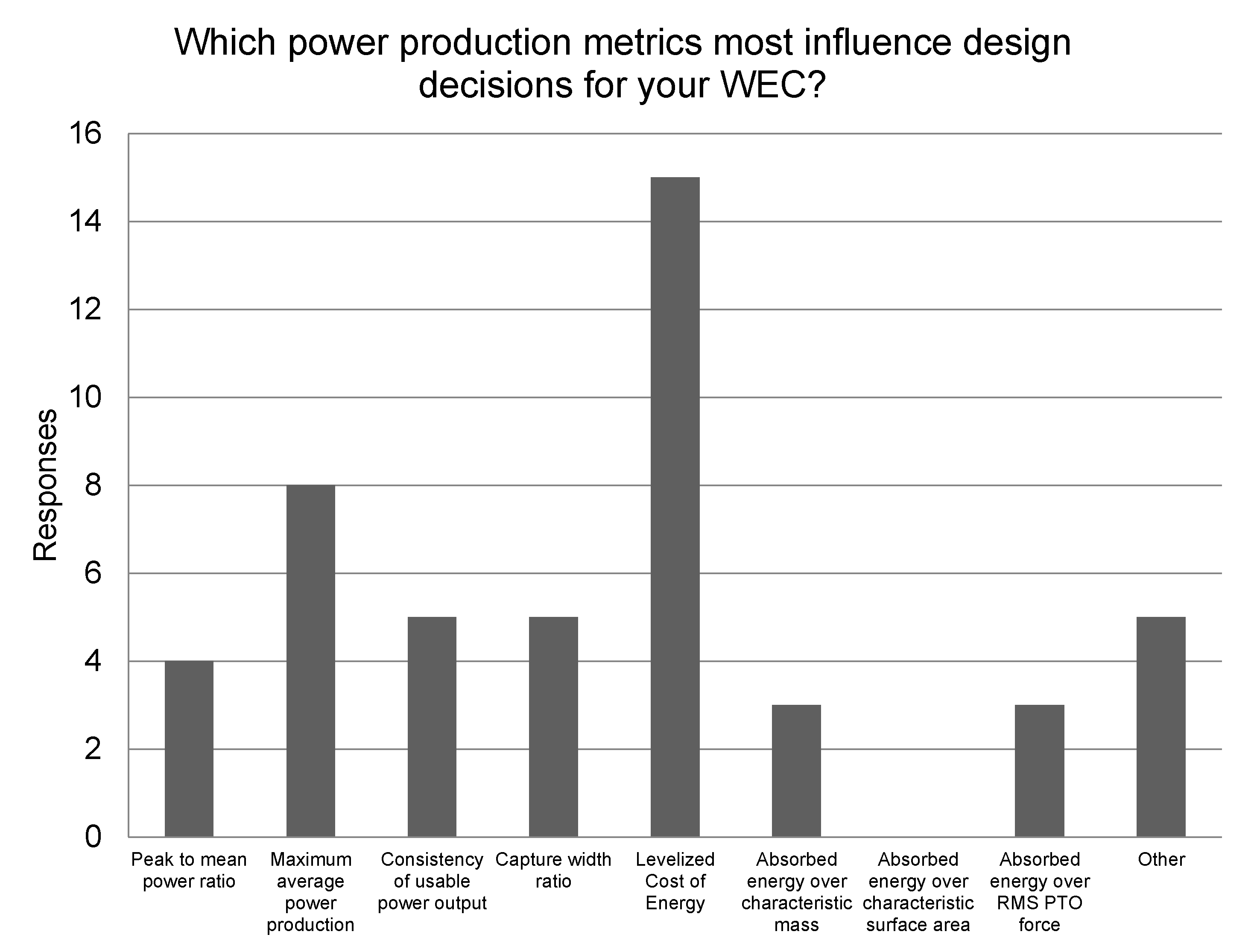
4.1. Power Production

The design requirement for power production captures the WEC’s ability to convert energy from the ocean waves to usable energy. For grid-scale WECs, this usable energy is electricity, although for some emerging markets it might take another form. Power production is commonly measured through MAEP [39,120], CWR [7], and transformed and delivered efficiency [121]. Researchers with DTOceanPlus recommend that CWR is used to measure performance of low-TRL devices and power matrices for higher-TRL devices [121]. Power matrices show the mean power (absorbed or converted) over a range of significant wave heights and average wave periods [38]. The DTOceanPlus project has created an assessment tool for “system performance and energy yield” which enables designers to assess device efficiency, alternative metrics of energy performance, energy production, and power quality. The documentation of that tool includes a number of other metrics that are used for power productions [122].
Design strategies to improve power production (as well as evaluation strategies) often depend upon the numerical models and simulations discussed in Section 3.3.1. Designers often create numerical models early in the design process and use them iteratively—modeling a system, simulating its performance, changing parameters to improve performance, and so on—as exemplified by Ruellan et al. in the design of the SEAREV WEC [60]. Once enough parameters have been defined, optimization methods can be used to improve power production. Parameters of the main subsystems of a WEC may be optimized to increase power production, including the WEC, PTO, controls, and moorings, but their interdependence can make the optimization processes more difficult as discussed in Section 3.4. The PTO, moorings, and control strategies all influence the motion of the WEC, indicating that improving power production may require those subsystems to be designed concurrently. Appropriate control design has the potential to double the energy output of a WEC [123]. The DTOceanPlus project has developed and released (May 2020) tools for energy capture, energy transformation, and energy delivery, each of which may be useful to improve device power production [102]. The wave energy field has not yet identified device-agnostic principles for improving power production, though Babarit et al. show that the device archetype does not automatically make a significant difference [7]. Identifying principles for improving power production could lead to early-stage design tools which can decrease the time and effort spent on numerical modeling, model validation, and simulation.

4.2. Capital Cost

The capital cost (CAPEX) of a WEC project includes all the expenses prior to operation, including design, procurement, manufacturing, installation, and permitting expenses [97]. Measured in national currency, CAPEX estimates are integrated into the LCOE calculation. Reducing the capital cost of WECs will be an important part of making wave energy a feasible renewable energy source. Chang et al. determined the need to reduce CAPEX and operational cost (OPEX) costs by about 45% to meet the cost-competitiveness goal of offshore wind energy of $0.30/kWh USD [25]. It can be difficult to evaluate the capital cost of WECs due to the limited experience across the industry building and deploying full-scale systems. As shown by Farrell et al., uncertainty is high, and costs are dependent on government policy [124]. Costello et al. identify important capital cost drivers as device surface area, device displacement, number of PTO units, maximum PTO effort, maximum PTO excursions, and maximum device power [125]. Factors outside the designer’s control, such as changes in policies and permitting practices also impact capital costs.
In order to design toward these CAPEX goals, designers must evaluate their own devices, increasing the fidelity of the evaluation as they move along through the design process. Estimates of CAPEX will increase in certainty as they increase in fidelity, and designers must remain aware of the level of uncertainty throughout the process. To evaluate CAPEX, designers can use baseline estimates from the offshore wind industry or the oil and gas industry to estimate the capital cost of a WEC. They can also begin with estimates from the marine energy Reference Models 3 [23], 5 [97], or 6 [98] (introduced in Section 3.3.1). Chang et al. begin with baseline values and use a mass ratio to estimate the CAPEX and OPEX of different devices [25]. Designers may choose to perform in-house cost estimates or to hire subcontractors for the job. Early cost estimates may be based on only the costs of the most expensive components of a device in order to simplify design and evaluation. A common design method is to simply use estimates of capital cost to identify the most expensive components or services (such as transportation of materials) and redesign those aspects of the system, i.e., [63]. This iterative method can be time consuming and is best coupled with methods which help designers make better decisions from the conceptual stages. To reduce capital cost, designers can employ design for manufacturing or design for assembly methods (discussed further in the Manufacturing and Material Selection Section 4.6) [107]. Eliminating components which are subject to major price fluctuations as well as decreasing the number, mass, and volume of components will also help reduce capital cost [126]. Later in the design process, capital cost can be included in optimization algorithms as discussed in the Section 3.4.

4.3. Operational Cost

OPEX can be defined as “all annual costs required to maintain optimum mechanical performance,” including scheduled and unscheduled maintenance and insurance [127]. O’Connor and Dalton divide OPEX into insurance costs, replacement costs, overhaul costs, and annual operations and maintenance. They show that common metrics for operation and maintenance costs are currency/MWh, percent of initial cost, percent of total OPEX, and percent of cost of electricity [127]. It is important to note that the most common metric, currency/MWh, is site-specific and should be qualified as such [25,127]. The metric of % of initial cost is a non-site-specific metric that is sometimes used for operations and maintenance costs (which make up a large portion of OPEX) [127]. Though the annual OPEX of a WEC is estimated to be 1–10% of the capital cost [128], it is more difficult to estimate given the lack of experience in WEC operation.
OPEX can be estimated by designers using many of the same methods as capital cost, and similar iterative design methods or optimization can also be employed. DTOceanPlus offers a System Lifetime Costs assessment tool [122]. The cost drivers for OPEX include accessibility and technology maturity, but have not been researched as extensively as the drivers of CAPEX [127]. For that reason, iterative design methods of reducing OPEX are less dependable. Designers can reduce OPEX by selecting components according to a lifetime maintenance schedule, synchronizing maintenance and reducing visits to the deployment site [120]. Designing components to be modular, durable, and adaptable will reduce operational cost affiliated with device failures, while automating routine maintenance and monitoring of the WEC system will reduce operational cost affiliated with personnel. Choosing components which are non-hazardous and recyclable helps to reduce decommissioning costs associated with environmental regulations, as noted in studies of oil rig decommissioning [129]. DTOceanPlus offers a logistics and marine operations tool to help designers plan operations [121]. Design for remanufacturing is the process of designing products such that the components or materials may be recovered and reused. Remanufacturing can be both economically and environmentally beneficial [130], and may be especially applicable for WEC designers building scaled prototypes. Harnessing the benefits of remanufacturing may also allow for opportunities to reduce capital cost and increase technology learning rates by making short-term deployments more economically feasible. OPEX research by O’Connor and Dalton suggests that “designers will need to choose whether to opt for longer lasting more expensive devices which require lower annual maintenance costs, or cheaper devices with short device lifetimes requiring overhaul mechanisms that enable easy and cheap retrieval from ocean site to maintenance dock” [127]. Rapid technology development based on fast learning rates and short diffusion timescales has been identified by Wilson et al. as an important factor for technologies intended to help with decarbonization [131], implying that in the early stages of WEC development, the latter option may be preferable. A final design strategy for reducing OPEX is to reach out to potential insurers early on in the design process in order to get estimates of insurance costs and begin working to decrease them.

4.4. Availability

Availability is traditionally defined as the amount of time a system is functional over the amount of time it is needed. Abdulla et al. argue that this traditional definition is not suitable for WECs because it “requires specifying the definition of a functional system” [132]. Instead, they define availability as the electrical energy generated over the electrical energy that would have been generated over the same period of time if there was no downtime. DTOceanPlus simply uses the percentage of time in which the WEC is producing energy [122]. The availability of a WEC has a significant impact on its annual energy production and OPEX, and therefore its LCOE [127].
In early stages of design, one may estimate the range of sea states for which the device is functional and use wave resource data to estimate availability along with a generic frequency of failure [133]. In order to estimate availability in such a way that it helps in design decision-making, designers may choose to create statistical models of availability as Abdulla et al. did for the Oyster-2 [132]. Abdulla et al. use power matrices, historical wave, tidal, and weather data, mean time between failure (MTBF) data for components, and maintenance timelines to estimate failure rates. They use OREDA, a commercial component industry database of MTBFs, to determine MTBFs and operational experience and they use operational reviews to determine maintenance timelines [132]. Designers can use models like this one to estimate the impact of system layout, preventative maintenance, system aging, wave height, and tidal restrictions on availability. DTOceanPlus offers a system reliability, availability, maintainability, and survivability assessment tool [121]. Improving availability requires designers to select and configure components such that they can handle failures [134]. WEC designers need to factor in the location at which repair will take place and the weather window necessary for repair if it is offshore [120]. This requires knowledge of offshore operations and meetings with stakeholders. Designing in redundancy for critical WEC functions and standardizing the fasteners, components, and tools needed for maintenance will also improve availability.

4.5. Reliability and Survivability

Reliability and survivability are closely related to availability. In fact, reliability, as measured through failure rates, is typically an input to an availability model [122]. We discuss it separately here because unlike environmental conditions and maintenance strategies, reliability can be extremely difficult to estimate (and thereby design for) for WECs given the lack of deployment experience. Clark and DuPont review the ways that wave and tidal energy researchers and developers have attempted to measure reliability, including factor approaches in which a base failure rate is multiplied by independent factors, accelerated lifetime testing approaches, and failure modes and effects analysis (FMEA) [135]. The International Organization for Standardization defines reliability as “the ability of a structure or structural member to fulfill the specified requirements, during the working life, for which it has been designed” [136]. Johannesson et al., members of the Swedish RiaSor 2 project, present a method of determining device safety factors through a Variation Modes and Effects Analysis (VMEA), a method which increases in complexity throughout the design stages and is meant to make up for shortcomings in the FMEA [137]. Johannesson et al. use the VMEA to perform fatigue design assessment [137], and Atcheson et al. use VMEA to quantify load uncertainties [138]. General reliability standards have been published by the British Standards Institution [139], while both the European Marine Energy Centre (EMEC) [140] and the International Electrotechnical Commission (IEC) [141] have published wave energy specific standards. Survivability is measured by the range of sea states in which a WEC can operate or the probability of structural failure [121].
Designing for reliability and survivability is rooted in calculations of load and fatigue. Destructive testing or load testing on components or prototypes for which performance data may not be available helps designers understand the weak points of their concept and the operational sea state range. Margheritini et al. used a 1:60 prototype equipped with pressure cells to measure the wave loading on the Sea Slot-cone Generator. They used the results to redesign the WEC to reduce structural loading [142]. Clark et al. use fatigue analysis to account for reliability in the objective function of a WEC optimization algorithm [113]. In earlier design stages, designers might use literature to understand common failures, as done by Boscaino et al. They perform what they call a “reliability-oriented approach” in which they do a literature-based failure analysis and develop a modular WEC to increase reliability [61]. FMEAs are also common in the early stages to identify the most likely failures and then perform low-cost, isolated testing and analysis [122]. Researchers from NREL and Sandia National Labs have developed a toolbox called the WEC Design Response Toolbox which is openly available on the WEC-Sim github. The toolbox includes environmental characterization, short-term extreme response, long-term extreme response, fatigue, and design wave composition capabilities and is meant to improve the WEC survival design process [143]. Altering the configuration of the WEC during high sea states can serve as a way to increase survivability, such as Oscilla Power has done with the Triton device [144]. To come up with such a configuration, designers can perform survival strategy storyboarding (described in Section 3.2.1). To improve survivability, designers can implement life-extending controls such as those discussed by Stillinger et al. [145]. Accounting for environmental factors such as the site’s water pressure, salinity (air and water), temperature variations, marine life, and extreme wave events when making structural and material decisions can improve reliability and survivability [146].

4.6. Manufacturability and Materials Selection

The manufacturing processes and materials selection for a WEC directly impact the CAPEX and the survivability. Manufacturability is typically measured in the time and cost of manufacturing [121]. The DTOceanPlus project has suggested a metric of manufacturing readiness level (MRL) which they borrow from the Department of Defense [121,147]. For designers, meeting the requirement for manufacturability means understanding the available materials and manufacturing processes such that they may design a device which can be manufactured with ease, at a low cost, and with minimal risk. To evaluate manufacturability, designers can make in-house estimates of manufacturing processes, timelines, and costs which are improved by reaching out to potential manufacturers. Involving manufacturers early in the design process can prevent designers from overlooking important factors [107]. When making in-house estimates, it is helpful for designers to look to other offshore industries, as they have to deal with similar environmental challenges to materials selection. Hudson et al. document the material challenges for WECs and how they impact the commonly-used materials. They discuss corrosion, fatigue, corrosion fatigue, wear/fretting fatigue, marine fouling, and impact loading and fracture and the causes, effects, and mitigation strategies for each of these challenges [148]. A report by the US Department of the Interior Minerals Management service identified applicable standards and codes for materials which included ISO 2394: 1998 (for testing of structural materials), API RP 2SM (for testing of synthetic mooring ropes), and DNV-OS-C401 (for testing of electrical equipment and cables). They also identify manufacturing guidelines which include API RP 2A-WSD, DNV-OS-C410, and the EMEC standards for manufacturing [149].
Few publications discuss WEC design for manufacturability and materials selection. Malca et al. discuss the influence of material selection on the structural behavior of a bottom-mounted linear hydraulic PTO point absorber [150], and Le et al. in the design of a bucking diaphragm WEC [151]. Le et al. use the Cambridge Engineering Selection Software (now sold as GRANTA Selector) to choose a material for the diaphragm of the WEC according to the required yield strength and bulk modulus [151]. They also detail an experimental set-up for materials testing [151]. Herrmann et al. summarize design for manufacturability (DFM) techniques which can be used in each stage of the design process as well as in concurrent engineering. DFM encompasses the consideration of product shape, size, material, and number of components [107]. Concurrent engineering is the practice of simultaneously designing a product and determining the manufacturing processes which will be used to make it [107]. Das et al. introduce Pro-DFM, a way to model and evaluate manufacturability based on procurement, handling, assembly, and inventory. Pro-DFM combines cost and manufacturability assessments to provide designers suggestions for low-cost product realization [152]. Using a resource such as Matweb, an online source for materials information, could help WEC designers find the appropriate materials [153]. Other methods that WEC designers might use to improve manufacturability include manufacturing storyboarding, stakeholder meetings with manufacturers, and materials selection based on finite element analysis [150]. Designers may add modularity to the WEC, standardize parts, and reduce custom component complexity. It is important for WEC designers to understand the materials and manufacturing processes which are available for them in the prototyping, one-off testing, and mass manufacturing stages of design. It is, of course, best to use the lowest-cost materials possible in prototyping, but when doing so, designers must know how those choices impact experimental results [106].

4.7. Installation and Maintenance

Installation and maintenance of offshore technology is much more expensive than for onshore technology, and is, therefore, an important aspect of WEC design. Installation duration and costs are the common measures of installability [121]. Designers may evaluate these qualities via simulations, prototype testing, or feedback from subcontractors. A report by US Department of the Interior Minerals Management service outlines relevant codes and standards for installation [149], but as with manufacturing, approaches for design for installability and maintainability in the early design stages are different from approaches in the later design stages which are guided by these standards. There is significant research on how installation and maintenance impact the economics of wave energy, i.e., [154], but less work on how WEC design decisions (including decisions about installation and maintenance strategies) influence installation and maintenance capabilities. Operational simulations which consider maintenance strategies have been introduced by Teillant et al. They consider unscheduled maintenance which occurs randomly based on an FMEA table [128]. The DTOceanPlus project includes Logistics and Marine Operations tools which aim to help designers with vessel selection, weather windows, and preventative and corrective maintenance planning [155]. Rémouit et al. discuss the applicability of divers and underwater vehicles in marine renewable energy installation and maintenance, identifying the situations in which one is more time and cost effective than the other [156]. Other design methods to improve installability and maintainability include storyboarding, the application of conceptual design methods to installation and maintenance strategies, and stakeholder meetings with installation and maintenance personnel. Designers may also consider combined installation with other offshore structures or integration into breakwaters [157]. Mooring design is highly influential on the installability and maintainability (as well as survivability) of a floating WEC farm [158]. Johanning et al., introduce a design methodology for identifying plausible station-keeping techniques [159]. Finally, designers might review publications and reports of other WEC installation processes such as [154] as Rinaldi et al. do for tidal deployments [160] and learn from other offshore industries [161].

4.8. Grid Integration

Integrating a WEC into an electric grid depends on the frequency of the output power, the consistency of the electricity production, the predictability of production [162], and how quickly production can be curtailed. Power electronics, energy storage, and control strategies directly impact grid integration [163] whereas array placement, distance from shore, and predictability of wave resource contribute to the consistency, predictability, and cost of transport of the produced power. The peak-to-average power ratio is a common measure of the quality of power produced by a WEC array [164]. Minimizing the peak-to-average power ratio has emerged as a research objective in array placement/optimization i.e., [165,166,167] as well as in control design, i.e., [41,164]. The standards for marine energy grid integration can be found in IEC TC114 62600 and power quality standards for wind energy can be found in IEC 61400-21, both of which are discussed by Kracht et al. in the MaRINET report on grid integration and power quality testing [168]. Power quality measures relate to minimizing both voltage and frequency fluctuations and include include reactive power and flicker coefficients (among other measures) associated with grid codes [168]. The MaRINET report on demand side grid compatibility offers methods for designing control systems and array layouts to meet grid codes [169]. Flicker is a measure of voltage fluctuations which is impacted by the WEC farm size and architecture, device type, control, and sea state [170]. Although the impacts of flicker depend on the grid strength [171], Kovaltchouk et al. present a method of evaluating flicker independent of the grid [170]. Blavette et al. point out that because site-specific grid compatibility studies are time consuming and require a lot of detail, developers often put them off. To address this issue, they present a method using DIgSILENT power systems simulator to simulate the compatibility of a WEC farm with a generic grid representations which vary in strength [171].
Short term energy storage such as hydraulic accumulators (i.e., [172,173]), flywheels, batteries, or super-capacitors have been subjects of research related to minimizing power fluctuations [38,75] as have power electronics [165]. Combining wave energy with other renewables has also been explored as a way to make systems more compatible with the electric grid, i.e., [2,174]. A numerical model which includes WEC control strategies, PTO, and power electronics is referred to as a wave-to-wire model. Wang et al. present a strategy for control design using wave-to-wire models [175], and Penabla and Ringwood present a method for developing high-fidelity wave-to-wire models. Iterative design using these models is a common design strategy, but since power system dynamics are on much shorter timescales than WEC dynamics, a complete wave-to-wire model can be computationally expensive [176]. Parkinson et al. and Reikard show methods for performing short-term forecasting and simulation of WEC-grid integration [162,177]. Designing to reduce sensitivity to wave direction and sea state and to improve consistency of power production is most effective if began during the conceptual design phase. As discussed previously, WEC design often begins with the design of the subsystem that absorbs wave energy, leaving consideration of grid integration until later in the design process. Considering the end use earlier in the design process may help to improve the integration of the WEC with the grid, or whichever other end use for which the WEC is designed by forcing designers to understand the power quality requirements of the end use early. This will help developers avoid making high-cost deployments without the necessary knowledge on how the WEC will integrate with the grid [176]. Grid integration requirements are, of course, less applicable for WECs that are designed for non-grid applications, but the steps that designers take to consider the electric grid in WEC design may be used as a model for how designers can design for any end use.

4.9. Environmental Impacts and Safety

The environmental impacts affiliated with wave energy have been researched rather disparately in areas related to noise and light impacts, habitat change, sediment transport, wildlife behavior, pollution, and impacts of electric cabling. There is not a standard way of measuring all environmental impacts, but regulatory agencies require their assessment [178]. Apolonia et al. propose a method for Environmental Impacts Assessment and Socioeconomic Impact Assessment for nearshore wave energy devices [179]. Willsteed et al. argue the need for cumulative environmental assessments of marine energy devices which can bring together environmental impacts research and place it in the context of climate change and other ocean uses [180]. To get the necessary permits for testing or deployment, WECs are subject to environmental impacts assessment [181] and safety requirements. Folley et al. point out that Boussinesq, mild-slope, and spectral wave models are more suitable for determining environmental impacts than potential flow models or QFD [85]. Design for improving safety and reducing environmental impacts has been piecewise, including noise reduction, elimination of hazardous fluids and components, and minimizing human–device interaction. Additional methods for improving operational-stage environmental impacts include prototype testing with data collection, tools for which are being developed by researchers [182]. Designing to reduce environmental impacts requires communication and work between scientists and designers, which methods of Ecological Engineering help to facilitate [58]. WEC designers could benefit from employing sustainable design/design for the environment (DfE) practices as well. Life Cycle Analysis (LCA) is one of the most popular tools in DfE, but it requires a fully defined product [183]. Telenko et al. present a compilation of DfE principles and guidelines that designers can employ in the conceptual and embodiment stages to lower the environmental footprint of a product [183], most of which are focused on resource use, which receives less attention in marine energy development compared to operational-stage impacts. Nature-inspired design strategies [184], remanufacturing, and optimization methods which integrate environmental impacts (as an objective or constraint) and safety (as a constraint) are all methodologies related to DfE. Marine energy has been identified as one of the major potential ocean-based solutions to address climate change and the effects of climate change on ocean ecosystems [185]. As wave energy expands its intended end-use, designers may even choose to design systems which address the current threats to ocean ecosystems.

4.10. Acceptability

The acceptability of a WEC can be difficult to measure given the irrationality of human nature. Nonetheless, with this requirement, we attempt to gauge the likelihood that a WEC project will be embraced by the local governments and communities. Measures of acceptability have been proposed by governance and human dimensions researchers in wave energy. Acceptability may depend on environmental impacts and safety concerns, but, Henkel et al. point out that “Coastal stakeholders’ support for offshore renewable energy technology may be based on perception rather than an understanding of technological specifics of a project” [181]. This means that we can make preliminary assessments of acceptability based on environmental impacts, safety, competition for ocean space, job creation, or even more detailed equity metrics such as the Gini coefficient [186], but ultimately, the acceptability of a wave energy project will be contingent upon the symbolic interpretations of both technology and of ocean place of the local community [187]. Testing is seen by the public as an important factor in the development of wave energy [188]. Researchers emphasize the need for good communication with the public and policy makers, participation in outreach or community partnerships by developers, and the creation of websites that are able to address the concerns of the public [188]. Though technical researchers often discuss the visibility of WECs from shore as an important factor to acceptability, social science researchers have shown that visibility is not a primary concern [189]. Acceptability may be achieved through design methodologies such as participatory design [190] and ethnographic need-finding [191], design for local manufacturing [120], and community engagement [188]. More non-traditional methodologies might include taking a site-specific approach which accounts for the community as part of the system via the principles of ecological engineering or even via engaging in customer co-design projects to build understanding of the WEC system and customize it to the needs of the specific community.

4.11. Global Deployability

The global deployability of a WEC encompasses its ability to operate in many locations which differ in terms of wave conditions, environment, geophysical conditions, socioeconomic status, energy demand, and manufacturing and deployment capabilities. The TPL assessment considers water depth requirements, geophysical requirements, minimum feasible wave resource, sensitivity to tidal range and current, impacts on environmentally sensitive areas, and necessity of specialized manufacturing, construction, assembly and installation tools [120]. Most evaluation of global deployability is via qualitative reasoning based on some fraction of these contributing factors. Researchers use Geographical Information Systems (GIS) datasets from projects such as that performed by Cradden et al. [192] to assess different sites around the world for their suitability for wave energy. Nobre et al. use a multi-criteria analysis method along with GIS to identify the best sites for a WEC deployment based on depth, sea bottom type, wave resource, other marine area uses, and several other factors [193]. Vasileiou et al. use a similar method for combined wind-wave systems [194]. Ghosh et al. use multi-criteria decision making techniques and artificial neural networks to index potential wave energy sites [195]. Each of these methods requires input criteria, some of which are based on the deployment requirements of the WEC. This, like many other methods in WEC design, leads designers into an iterative design process of defining the details of a concept, understanding the site requirements based on those design decisions, determining the deployability, and then redefining the details of the design based on the potential deployment sites. Where WEC design strategies fall short is in the interplay between the WEC parameters and the site requirements. There are no methodologies which help designers make decisions which improve/expand the deployability of the WEC other than the iterative process described above, and even then, we have limited data on how specific design decisions expand or constrain deployability.

5. WEC Designer and Developer Methods

In order to give a complete review of WEC design methods, it is important that we discuss the methods employed by WEC designers, not just those present in research. Given that industry designers and developers do not regularly publish in academic journals, we combine our literature review with an analysis of survey results from WEC designers to integrate that perspective and complete the picture. We surveyed 25 respondents, 20 of whom identified themselves as WEC developers (either designers or supervisors), four academic researchers, and one researcher from a national lab or similar entity in order to fill this gap in knowledge of the WEC design process. The qualification for participation in the survey was that the respondent must have participated in the design of a WEC which has been tested in the water. This could include scaled prototypes and testing in tanks, flumes, oceans, or other bodies of water. Although this qualification allows for a wide range of development stages, it guarantees that designers have at least made it through conceptual design and significant portions of the embodiment design stage, which is where most of the methods we asked about would be applied. We eliminated responses based on WEC design projects which were completed in order to create test platforms. Participants were self-selected and anonymous. We use this survey data along with the knowledge of the WEC design process detailed above to identify trends in WEC design methods, common tools and approaches, gaps in methodologies, and areas for improvement of the WEC design process.

5.1. Survey Overview

The WEC Design Methods Survey began with baseline questions about the role that the respondent has in WEC design and how the primary device archetype was selected for their design project. The second section of the survey asked which general design approaches/philosophies and conceptual design methodologies the respondents employed. We asked at which point in the design process a deployment site was selected. For most questions, respondents were allowed to select more than one answer. The remaining eleven sections of the survey asked the same set of questions for each of the eleven design requirements. Respondents were asked what design methodologies/tools they use to design for a particular requirement, what methodologies or tools they use to evaluate success under that requirement, at what point in the design process they began to consider a particular requirement, how often (scale of 1–10, Never to “Every time I make a design decision”) they consider the requirement, and how satisfied (scale of 1–10, “not satisfied” to ”I highly recommend them”) they are with the methodologies and tool available to them for designing for the requirement. In the power production section, we also asked the order in which the design team designed subsystems of the WEC and the power production metric which most influences their design decisions. Respondents were asked to respond to the best of their knowledge regarding their project as a whole, not just their personal experiences. For example, if the design team uses CFD, the respondent should select CFD even if they do not personally work with CFD. Respondents were able to skip questions, but any response with entire sections left blank were deleted to ensure the quality of the data collected. We did not ask for any personally or professionally identifying information in the survey in order to protect the privacy of individuals and companies. This means that we are unable to connect the responses to particular devices and thereby make conclusions about how well particular methods work, but we believe that requiring that information may have deterred many respondents from participating. Nonetheless, we are able to get a good idea of what methods designers are using and how satisfied they are with those methods.

5.2. Survey Results

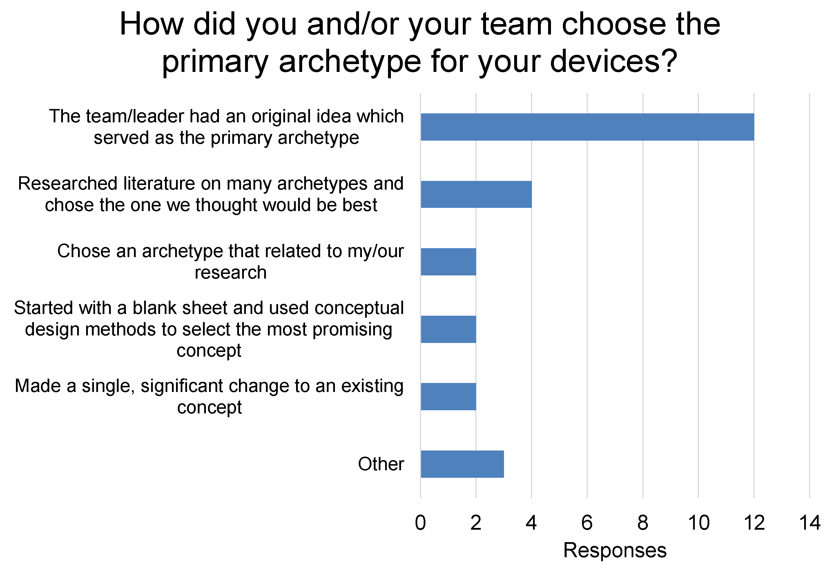
5.2.1. Design Philosophy and Conceptual Design

Respondents were asked which design approaches they used to shape their overall design process. The results are shown in Figure 5. The three most popular responses were the three most traditional approaches—spiral design, Systems Engineering, and product design methods. This is consistent with the literature we reviewed, where Systems Engineering approaches and product design methods such as QFD were emphasized by both federal-level research groups [9,11] and independent researchers [33]. The spiral design process is embodied in the piece-wise innovation of the projects discussed in Section 3.2 [60,61,62], and is not considered a good methodology for reaching optimal solutions [55]. That said, spiral design is popular in software engineering and known for its emphasis on risk assessment [196]. The popularity of spiral design indicates a need for researchers and designers to continue to apply and publish the results of more structured methodologies. The three popular approaches were also the only approaches which were selected by the nine respondents who only selected one approach, indicating that designers do not consider any of the other approaches to be sufficient for stand-alone use (most of which are not intended for stand-alone use). In all five instances that a respondent selected Set-Based Design, they also selected spiral design and Systems Engineering. Set-Based Design and Systems Engineering are compatible approaches, but combining Set-Based Design and spiral design likely requires some alterations to each approach. Effective alterations might include using Set-Based Design for the conceptual design stages and Spiral Design for embodiment and detail design, or using the spiral design process on multiple concepts until they are all well-enough developed to select the best one. All respondents who selected Ecological Engineering Principles, Axiomatic Design, Hierarchical Decomposition, Ethnographic Design, QFD, whole system trades analysis (WSTAT), SWOT, or Decision-based design also selected three or more other approaches.
Figure 6 shows how the respondent and/or their design team chose the primary archetype for the device. Nearly half (12 out of 25) of the respondents answered that the team or the team leaders had an original idea which served as the primary archetype. This method of choosing a design project is common, though it is considered to be a weak strategy which relates to premature commitment to a concept as is exemplified by the vast body of conceptual design research. Schmidt and Calantone point out that managers who built projects on original ideas are less likely to acknowledge when a project is failing. They call this ”escalation of commitment,” and determine that it is a major problem in new product development [197]. Only two of the respondents went though a conceptual design process to select the primary archetype. Given the importance of conceptual design to the success of a product [198], this data shows the need to more broadly employ traditional conceptual design methodologies to WEC design, as well as the need to develop conceptual design methodologies better suited to the challenges of WEC design. The fact that many WEC designers do not perform structured conceptual design is reflective of the general lack of literature covering the topic for WEC design (as discussed in Section 3).
Although conceptual design methods are not popular for choosing a primary archetype, 18 of the 25 respondents reported using conceptual design methods at other points in the design process. The most popular methods were mind mapping/brainstorming (11/25 respondents) and design structure matrices (6/25 respondents). Biomimicry and C-sketching were not used by any respondents, and brain writing (1), morphological matrices (1), TRIZ (2), computational concept generation (2), and Functional Decomposition (4) were each used sparingly. The popularity of “brainstorming” is unsurprising, given that the term is sometimes used as a blanket term for coming up with ideas. The use of some of these methods outside of the system-level conceptual design phase indicates that many researchers are decomposing the WEC into multiple subsystems. Designers may be more comfortable with applying these approaches to subsystems because other decisions that have already been made regarding the WEC design provide the constraints necessary to make the evaluation of subsystem/component concepts less uncertain. For example, it is easier to evaluate (with certainty) concepts for a hydraulic PTO subsystem given the constraints of the prime mover than it is to evaluate how well a specific WEC archetype will meeting the numerous design requirements. This indicates that within conceptual design, WEC designers may benefit from new methods of dealing with uncertainty such as that discusses by Malak et al. in Section 3.2.1 [81].

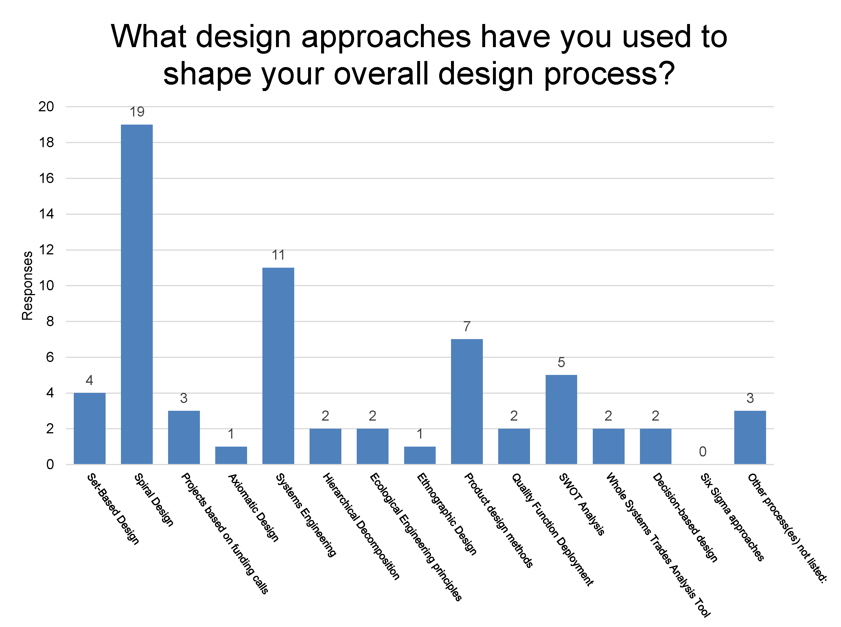
5.2.2. Common Design Methods

Table 1 shows all of the design methods and tools that are employed by 12 or more of the 25 respondents, our chosen benchmark for a “commonly used method” which indicates a level of convergence by the industry on that method. We recognize convergence as indicating one of two things; that the industry has reached a best available approach or that the industry has adopted an imperfect approach according to norms of another industry or engineering tradition. A lack of convergence indicates that there is no clear best option, and it can also indicate disorganized knowledge about methodological options or differing needs of specific projects. Using only survey responses, it can be difficult to determine the implications of convergence/non-convergence on design methods for the industry, but when we use knowledge from the literature reviewed in the rest of this paper, we can make an informed analysis.
From Table 1, we see that there are 22 methods (out of 100 different options across the 11 requirements) used by 12 or more of the 25 respondents throughout the 11 WEC requirements. Using wave resource assessments to design globally deployable WECs was the most commonly used method, followed by the iterative design of WEC and PTO subsystems by modeling, simulating, changing parameters, and returning to the modeling stage. The iterative method of improving power production is similar to the process described by Portillo et al. [45] and discussed in Section 3. An iterative method was also most common for reducing capital cost. As discussed, iterative methods can be slow, are unlikely to lead to an optimal design, and can lead to many costly late-stage design decisions [55], leading us to conclude that this convergence is more a reflection of engineering tradition than best practice. The selection of components based on lifetime maintenance scheduling, though an important method, only addresses one element which affects availability–planned maintenance [132]. Designers did not converge on a method for designing for availability related to failure reduction. For installability and maintenance, environmental impacts and safety, acceptability, and global deployability, designers converged on methodologies recommended by the DTOceanPlus and WaveSPARC projects. There were no common practices for designing to reduce operational costs or for grid integration, and only one for capital cost and availability, indicating the need for continued research toward best practices in designing for each of these requirements.
Despite the popularity of optimization in research, no optimization method was used by more than half of the designers, indicating that none of them have been adopted as best practice. The disparity may be due to the background knowledge needed to use optimization methods effectively, the number of ways that optimization can be applied, or the differences in the way designers prioritize the different design requirements. Given the minimum requirement of the survey that survey respondents must have tested their device in the water (tank testing acceptable), there is a chance that some of the respondents simply have not made it to an optimization stage in design. In Table 2, we show all of the optimization methods that we asked respondents about and the percentage of respondents who use each method. Controls optimization and hydrodynamic optimization to determine WEC shape and/or size were the most popular methods. Given that hydrodynamic optimization appears in Figure 2 as the first step of detailed design, it is surprising that the use of the method is not more common among designers. It is worth noting that when designers optimize using capital cost, they more often try to estimate capital cost rather than use a representative measures such as mass or volume. Operational cost, availability, variability, and installability/maintainability, are more often used in optimization algorithms as objective functions rather than constraints, while environmental impacts and safety measures are used equally as objective function and constraint.
For each design requirement, at least half of the respondents used multiple methods for design and evaluation of the requirement, as shown in Table 3. In many cases, satisfying requirements demands the employment of multiple approaches. For instance, when considering survivability, designers need to consider the impacts of all possible wave conditions as done by Mundon [144] while also considering the challenges to survival due to marine life, sediment, and salinity [146]. Accounting for both of these challenges to WEC survival can, understandably, require multiple design methods. Evaluation methods can differ according to the stage in the design process. As designers move toward better defined concepts, reducing uncertainty, they might move toward more detailed evaluations. For instance, in early stages of design, a WEC developer might make cost estimates in-house based on stakeholder engagement and/or estimates from other offshore industries, while later they might choose to hire a subcontractor such as done by Cordinnier et al. [63] to make more project-specific estimates. We discuss commonly used overall metrics and evaluation methods in the next subsection.

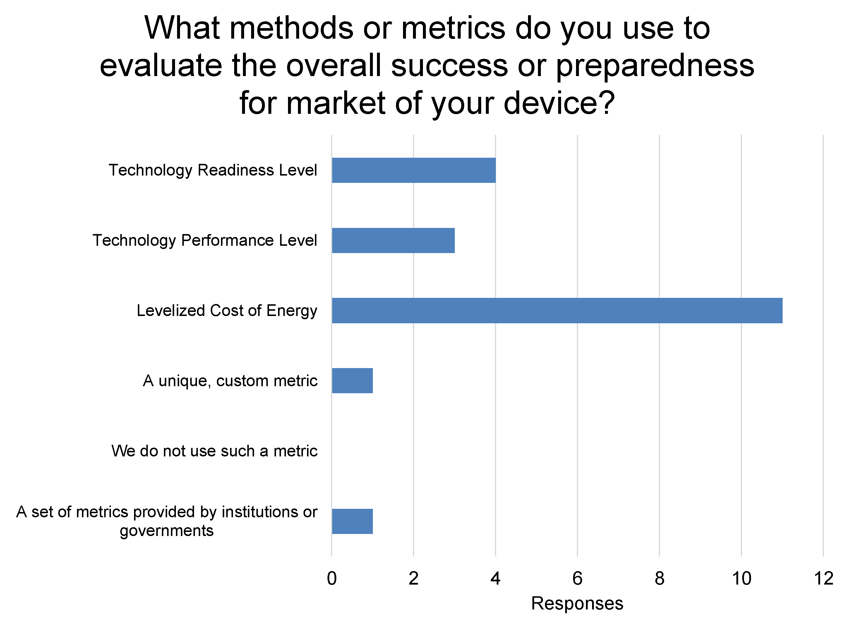
5.2.3. Common Metrics and Evaluation Methods

We asked designers how often they considered each design requirement. Knowing what requirements a designer considers important can help us to understand why/how they select certain metrics and evaluation methods. Figure 7 shows the responses with minimums, maximums, means with standard deviation, and outliers. For each requirement, there is a wide range of answers, with the response of 10 indicating that the designers consider that requirement every time they make a design decision, 7–8 indicating most of the time, 5 about half the time, 2–3 sometimes, and 0 never. The wide range could indicate that designers, on the whole, have a hard time relating individual design decisions to design requirements. For example, it may be difficult to consider availability when making a decision about device geometry if the designer does not know how a specific change in device geometry influences the design parameters which determine availability. At the same time, there may be design decisions by which a design requirement is not (or does not seem to be) affected, and therefore designers do not consider it. To continue with the same example, maybe the designer does not think that their choice of device geometry influences availability. QFD might help designers understand when a design requirement should be considered by requiring them to relate customer requirements to design specifications [14]. Researchers should take steps toward clearing up some of these relationships as well, especially for the requirements which have the largest standard deviation of answers-availability, grid integration, environmental impacts and safety, and acceptability. In Figure 7, power production, hydrodynamics, capital cost, and survivability, all have a mean above 8 with a standard deviation below 2. These requirements are the ones considered, on the whole, most often. Acceptability and grid integration had the lowest mean ranking, with the mean designer considering the requirement just over half of the time.
Figure 8 shows the methods/metrics that designers use to evaluate the overall success or preparedness for market of their devices. LCOE is clearly the most commonly used. It is also the most influential metric regarding power production, shown in Figure 9. This is reflective of a significant body of research on how to estimate LCOE for WECs discussed in Section 2.3, e.g., [23,25,34,35,36], but does not seem to reflect the level of uncertainty associated with the metric [24,37]. Despite researchers’ claims that LCOE is not the best metric for WEC performance, it is clear that designers do not see a viable alternative. We can see from Figure 8 that TPL assessment [32] has not yet been widely adopted as a metric for success/preparedness. In Figure 9 we see 23 positive responses for metrics that account for both power and cost (two from the “other” category) and 22 positive responses for metrics which did not involve cost directly.
Aside from LCOE as a common metric for both overall performance and power production, there are several other requirement-specific evaluation methods used across WEC design. Table 4 shows the evaluation methods (for all categories aside from power production) which are used by 12 or more of the 25 respondents. There were no common methods of evaluation in the categories of grid integration, environmental impacts and safety, and acceptability. This could be because these are considered more as binary requirements by some (a concept is either able to be integrated or not, safe or not, etc.) or because there simply are not satisfactory methods of evaluating these requirements. LCOE appears twice more as a common method for evaluating capital and operational cost. The next most popular evaluation method is using numerical simulations of extreme seas to evaluate reliability and survivability, e.g., [144]. Dynamic modeling and simulation make up a large portion of WEC research leading to robust evaluative capabilities for understanding the system dynamics and power production (discussed in Section 5.2.4). Table 4 shows that designers lack similar capabilities to evaluate the WEC in terms of other system requirements.

5.2.4. Dynamic Modeling

We asked designers about specific software tools as well as methodologies for dynamic modeling of WEC devices. A total of 21 of the 25 respondents use time domain simulations with hydrodynamic modeling, which, as mentioned, is required in order for designers to account for device nonlinearities [104]. This is consistent with the considerable amount of research which takes advantage of time domain simulations. Of those 21, nine model the system hydrodynamics linearly, seven use weakly nonlinear approaches, and five model nonlinear hydrodynamics. This could relate to the type of device, stage of development, or experience of designers [87]. CFD methods are used by 11 of the respondents. Five respondents use WEC-Sim [91]. Nine respondents use frequency domain simulations. Of the boundary element solvers, WAMIT was the most popular (nine respondents) followed by Ansys Aqwa (7), then NEMOH (4). Other software used by one or two respondents included Rhino mesh simulator, Orcaflex dynamic analysis software, and Flexcom Wave WEC simulator. No respondents use ProteusDS dynamic analysis software. Knowing the common software used in industry may help researchers decide which to use for their own work.

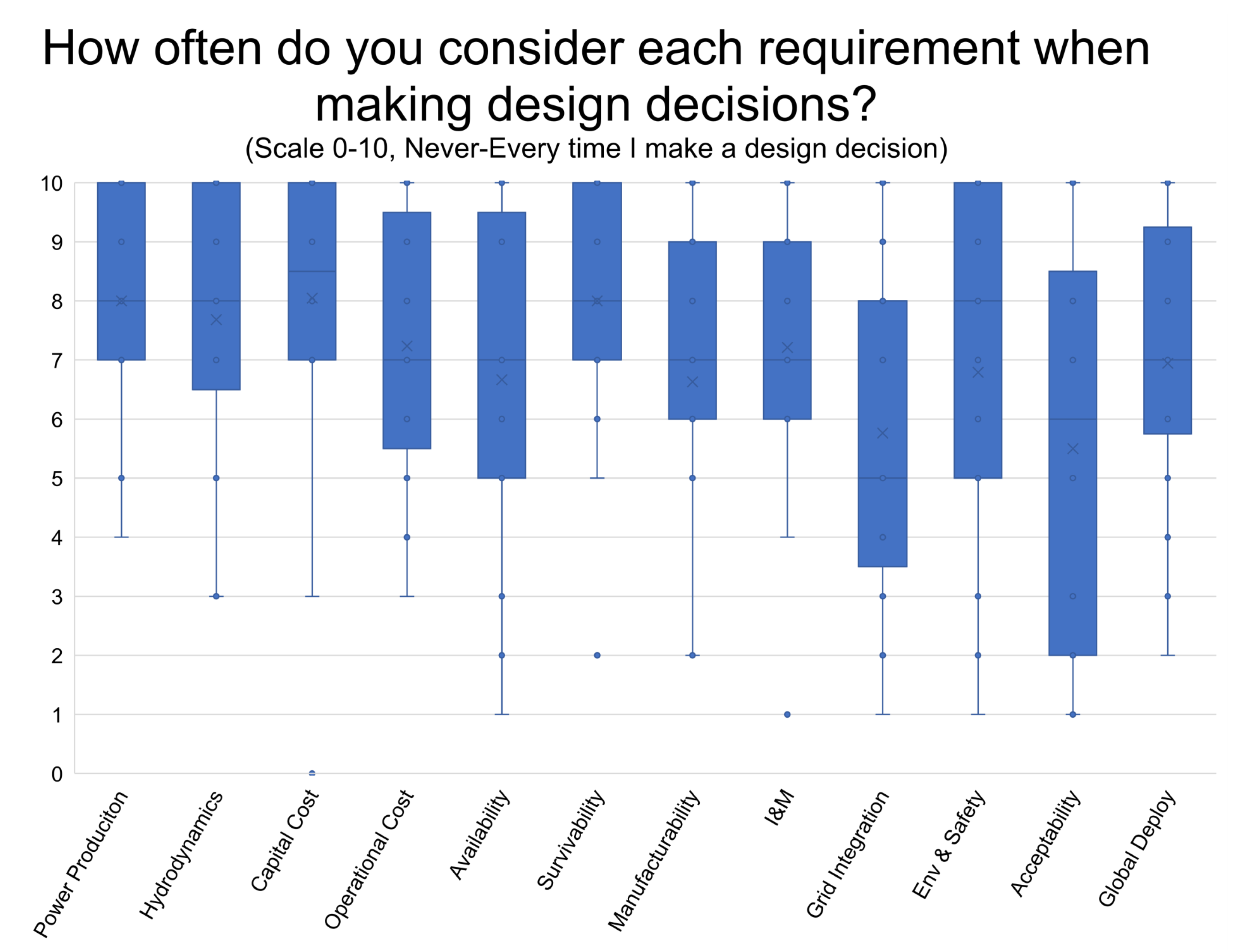
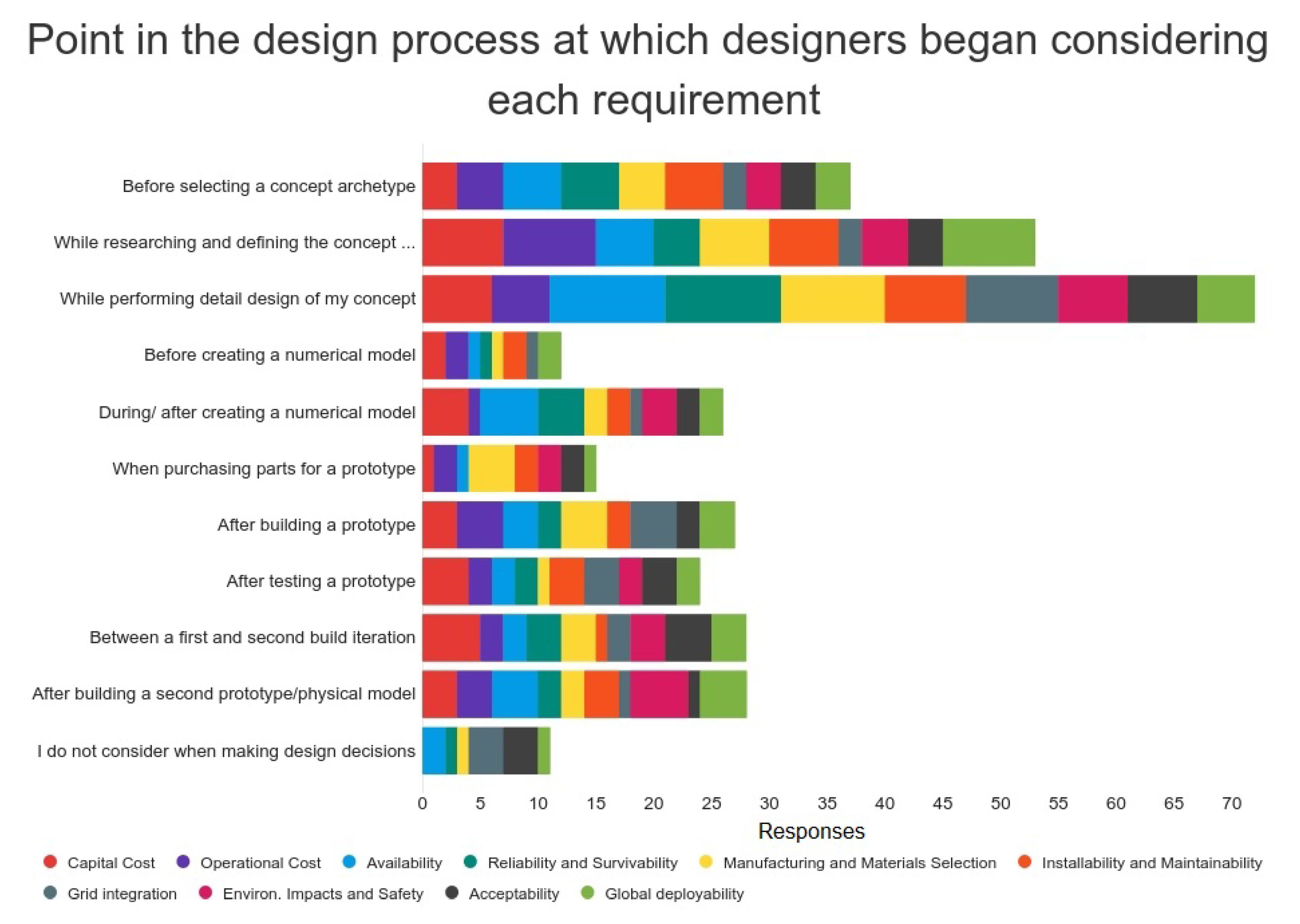
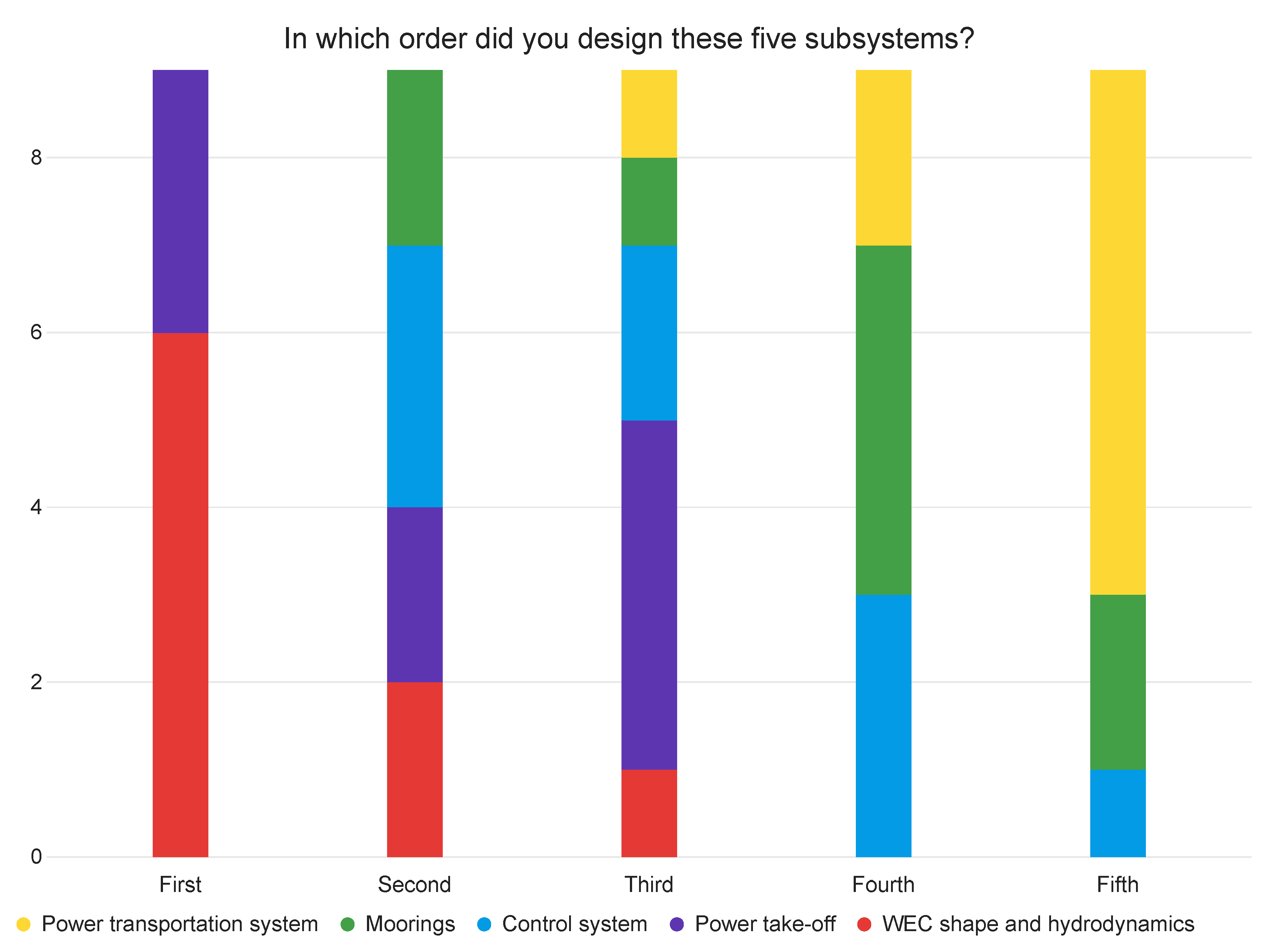
5.2.5. Timeline of Requirement Consideration and Subsystem Design

We asked respondents at what stage in the design process they began to consider each requirement. As a result that the process of designing a wave energy converter does not follow a prescribed pathway, we gave designers 11 options for responses and allowed them to select multiple options if appropriate. Figure 10 shows the collective responses, in the order that they were presented to respondents. It is a possible sequential order for WEC design aside from the placement of detail design. Although While performing detail design is the most commonly selected option, it is also one of the least informative data points given that different designers may have different definitions of detail design, just as we have defined detail design in this paper a bit differently than Portillo et al. did in Figure 2. Analyzing the other response options, we see that for each requirement, there were five or fewer respondents who considered the requirement before selecting a concept, which supports that conclusions of the literature reviewed in this paper which calls for improved conceptual design strategies [47,49,50]. Grid integration had the fewest considerations (2) prior to concept selection as well as during research/concept definition. For each requirement, there were respondents (though few) who did not consider the requirement until after building a second prototype or not at all. From design research, we know that considering all design requirements early in the design process leads to higher-performing concepts [200], therefore Figure 10 shows us that we still have work to do when it comes to giving designers the tools they need to do that.
When we asked respondents the order in which they designed five subsystems of the WEC (WEC, PTO, control, moorings, power transport), 18 responded. Nine of the designers responded that they designed the WEC, PTO, control system, moorings, and power transportation subsystems concurrently. Figure 11 shows the order in which the remaining nine respondents designed the subsystems. Generally, we see that WEC designers design the WEC subsystem and PTO in the first half of the process and the power transportation subsystem in the second half. Mooring and control design lingered in the middle. This order resembles the order suggested in the MaRINET2 publication on instrumentation best practice [102], but the fact that half of the respondents said that they designed the subsystems concurrently indicates a shift in industry toward co-design following that suggested by some control designers [75]. There is a significant space for further research on how those concurrent subsystem design processes should be carried out in wave energy.

5.2.6. Deployment Site-Agnostic Design

Of the 25 respondents, 10 indicated that their WEC was designed to be deployment-site agnostic. A deployment-site agnostic device will likely have a slightly different set of requirements than those discussed in this paper. Global deployability would likely be of higher importance; there might be different methods used for modeling given the need to understand performance in many different conditions; and the ways of designing for and evaluating manufacturability, installability, grid integration, environmental impacts, and acceptability might be different due to the fact that the designers need to satisfy the requirement for many potential sites. We did not find any notable methodological differences between the designers who claimed their WEC was site-agnostic and those who did not, but the sample size was too small to say definitively that methodological differences do not exist. This challenges us to question whether site-agnostic or site-specific approaches are better for WEC development and what changes would need to be made to current design processes for either approach. Committing fully to site-specific or site-agnostic design would lead to slightly different stakeholder and functional requirements than those addressed in this paper. Furthermore, different design philosophies would be useful for site-agnostic vs. site-specific approaches. For example, the principles of Ecological Engineering would not be suitable for a site-agnostic project, given the second principle’s emphasis on site-specific design. While site-agnostic design might seem financially appealing, site-specific design could help wave energy gain the support and thereby experience needed to continue development. Further research in design theory and direct comparison of site-agnostic and site-specific projects may shed light on the best pathway forward.

5.2.7. Designer Satisfaction

For each design requirement, we asked respondents how satisfied they are with the tools available to them for meeting that design requirement. They responded with a score between 0 and 10 (“not satisfied” to “I highly recommend them”). All requirements, except for capital cost, had a satisfaction range of nine or more, meaning every requirement area had both satisfied and unsatisfied designers. Capital cost had a range of eight. There were no requirements for which respondents were significantly more dissatisfied with the methods and tools available. The mean levels of satisfaction were between 4.9 (availability) and 6.66 (power production). Availability, operational cost, and grid integration were the requirements for which respondents were least satisfied, but when normalized by the individual respondent’s average level of satisfaction, availability, installation and maintenance, and grid integration received the lowest scores. Eight respondents gave availability the lowest score, three for installability and maintainability, and two for grid integration. Given the variability in how much designers attend to each requirement shown in Figure 7 and Figure 10, the variability in satisfaction is not surprising.

5.2.8. Under-Utilized Methods and Choosing a Method

Throughout this paper, we have identified and provided resources for numerous design methodologies which could be employed in WEC design. Choosing which to use may seem overwhelming (although design researchers such as Giambalvo et al. have published work intended to help designers choose [201]). Academic researchers we can further help designers choose methodologies by testing the methodologies and developing them to be more applicable to the unique challenges of WEC design. Some tools and methodologies which are worthwhile for continued research in WEC design include:
  • Set-Based Design.
  • Ecological Engineering.
  • Axiomatic Design.
  • Ethnographic Need-Finding.
  • Participatory Design.
  • Quality Function Deployment.
  • Conceptual Design Methods.
  • Installation Storyboarding.
  • Redundancy of Critical Function.
  • Subsystem Co-design.

6. Conclusions

From a design theory standpoint, wave energy development includes some of the most difficult aspects of both product and systems design. Like product design, WEC design requires designers to create custom components by identifying customer needs, generating concepts, and detailing designs using models and prototypes. Like systems design, WEC design involves the integration of subsystems of off-the-shelf components and the need to satisfy multiple levels of stakeholders [31]. WECs, whether for grid applications or emerging markets, are systems which are embedded into other complex technical (the grid/emerging market technology), economic (the electricity market), social (coastal communities), and natural (the ocean) systems upon which the WEC designer has little control. Despite the designer’s inability to control these larger systems in which their designed artifacts operate, they must understand the impact on the larger systems (such as grid impacts, environmental impacts, and acceptability), and must be able to respond to changes in those systems (such as changing energy policies). Each of these larger systems is changing in response to the same societal need that drives the design of those systems—the need for low-emission energy [185,202]. The ocean, furthermore, makes prototyping and testing difficult and poses major environmental design challenges [146]. The harsh yet endangered ocean ecosystems lead to the amplified need for highly reliable, low maintenance, easy-to-test systems with minimal negative environmental impacts. These changing contexts make prioritizing design requirements a challenging task. The need for low-emission energy will not be entirely fulfilled by wave energy, meaning wave energy development is both in competition with and reliant upon the development of other renewable energy technologies [2]. This can make it difficult to benchmark a technology against others on the market in a meaningful way. The unique challenges of WEC design, the fact that it does not fit neatly into any one design framework, and the fact that it requires the consideration of many systems considered to be outside of the boundaries of the designed system demand that we reflect upon and improve our current design strategies.
Through this review, we observe an emergent pattern in WEC design. Researchers have made and continue to make significant strides in evaluative techniques for WECs. This is understandable, given that in order to design toward specific requirements, we must first be able to evaluate performance in terms of those requirements. As these evaluative techniques emerge, academic researchers have focused on embedding these evaluations into optimization algorithms as a primary design methodology. As we see from the survey results, these optimization techniques are not being universally adopted by WEC designers. This could be for a number of reasons, including the time and computational demands of complex optimization problems. Furthermore, optimization algorithms cannot be entirely depended upon to integrate all of the requirements of a WEC. This leaves WEC designers using mostly iterative design methods in which they define the parameters of a WEC then evaluate performance under a single or a few requirements, often using qualitative methods for evaluating requirements which are not evaluated within numerical simulations. Once they have evaluated the performance, they redefine the parameters of the WEC according to its observed weaknesses, then return to evaluation. Although this iterative process is an essential element to engineering design, it leaves a lot to be desired in terms of guiding designers toward initial concepts with the potential for high performance. The iterative process also lacks guidance for using the output of WEC evaluations to make design decisions that improve performance as measured under the multiple WEC performance criteria. When it comes to improving WEC design, iterative techniques are only as good as the evaluations upon which they are based and the understanding of the relationship between individual design decisions and the results of those evaluation. In this paper, we have presented some existing design techniques that might be able to address the shortcomings in the WEC design process and we have identified areas where new design techniques would be beneficial. The DTOcean and DTOceanPlus projects have created openly-available design tools, discussed throughout this paper, in order to satisfy some to the gaps in WEC design and begin standardizing the process [9]. Their tools will need to be accompanied by design techniques which are developed, tested, and improved by wave energy researchers. A few important areas of future research are listed below.
  • Relating design decisions to customer requirements It will be the role of researchers to clarify how different design decisions impact a WEC’s ability to meet each design requirement and to create the tools that can help designers understand, visualize, and quantify those impacts. An example of such a tool would be one that relates design parameters to deployment site criteria in order to characterize how individual design decisions impact the wave resource available globally to a WEC.
  • Early assessment of all design requirements Although usable power production is the primary goal of WECs, and improving power production continues to be the main focus of much of the academic research, wave energy development is at a point where many of the methods of energy absorption and conversion are well understood. For that reason, designers will need to begin to consider requirements other than power production and hydrodynamics earlier and more often. This will require assessment techniques geared toward WEC concepts with high uncertainty.
  • Addressing grid integration and end use Grid integration is a requirement that consistently stood out among others. There were no common design or evaluation methods for grid integration, it was the requirement considered least often when making design decisions, the fewest respondents considered it prior to concept selection, and it was one of the requirements for which designers were least satisfied with the tools they had available.The widespread use of LCOE as a performance metric may contribute to the challenges designers face in designing for grid integration. The metric does not value any ancillary benefits that WECs could provide to the grid, which could become more important as more renewable energy sources come online. WEC designers need better tools for considering grid integration which are less computationally expensive than wave-to-wire models and do not require a fully-defined WEC concept.
  • Conceptual design processes As has been emphasized in previous WEC design research, engaging in structured conceptual design processes stands to save WEC designers time and money. With so many WEC concepts being proposed, conceptual design methods can help designers begin with a clean sheet. Concept evaluation methods can offer designers opportunities to evaluate concepts before creating detailed models.
  • Exploring new design philosophies As we have seen throughout this paper, systems engineering approaches tend to dominate the WEC design process although other design philosophies such as Ecological Engineering, Set-Based Design, and User-Center/Participatory design for emerging market WECs have the potential to guide WEC design in new directions. Further research is needed to determine whether any of these other design philosophies will lead to improvements in WEC design.
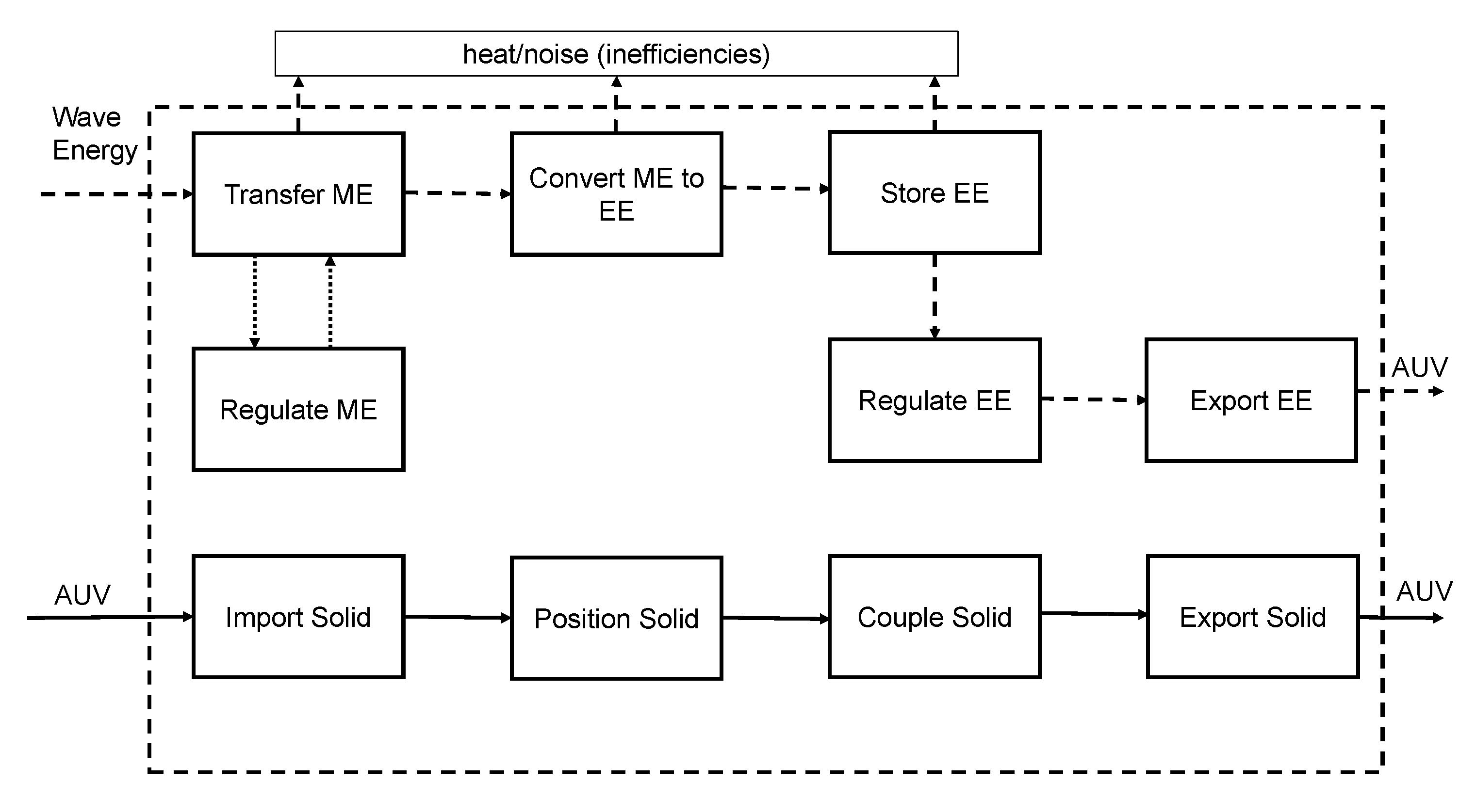
  • The impacts of model surrogates As discussed in Section 3.3.1, WEC designers may use surrogate representations of subsystems in early numerical models of WECs. How they do so depends on the prioritization of subsystems, which we analyzed for the survey respondents in Section 5.2.4. No research exists which explores the impacts of using these surrogates on the eventual performance of a WEC device. Such research could better inform design approaches (such as the extent to which co-design should be implemented), as well as the way that designers decompose WEC subsystems.
  • Materials selection at various design stages Prototype testing and the deployment of scaled WECs will be essential to gaining the experience necessary to drive down costs, reduce risk, and gain acceptance in the public eye. Gaining a better understanding of what components can be tested and what investigations can be performed at various scales of prototyping and how results scale to the full-sized WEC can help researchers and developers determine ways to cut material and manufacturing costs of prototyping.
  • Need-finding and site-specific design Given the opportunities for WECs which include grid-scale development and emerging market off-grid development as well as the driver of WEC development—climate change—there is more than one potential path for wave energy. Although we summarize stakeholder and functional WEC requirements in this paper, a particular project or site will have its own set of unique requirements. Developers should not forgo the need-finding design practices that allow them to determine those unique requirements. Just as the device requirements are site-specific, researchers have shown that the economic viability of a WEC is also site-specific. These facts challenge us to more closely evaluate the meaning and value of technology convergence and global deployability to determine the best pathway for WEC development. The pathway chosen will, as discussed, impact which design methodologies which are most appropriate.

Funding

This research was funded by US Department of Energy award number DE-EE0006816.

Acknowledgments

The authors would like to thank Jochem Weber of the National Renewable Energy Lab, Jesse Robert of Sandia National Labs, and Budi Ganawan of Sandia National Labs for supplying contact information for WEC developers. They would also like to thank all of the respondents for their time, participation, and inquires. Thank-you to Benjamin Maurer for his feedback and Christian Ransmeier his assistance during survey development. A. Trueworthy would like to acknowledge Daniel Gaebele and Austin Berrier for suggesting many helpful references and Matt Leary for draft feedback.

Conflicts of Interest

The authors declare no conflict of interest.

Abbreviations

The following abbreviations are used in this manuscript:
WECWave Energy Converter
PTOPower Take-Off
LCOELevelized Cost of Energy
CWRCapture Width Ratio
MAEPMean Average Energy Production
NPVNet Present Value
IRRInertial Rate of Returns
PBPPayback Period
HPQHydrodynamic Performance Quality
ACEAverage climate capture width divided by characteristic capital expenditure
TRLTechnology readiness Level
TPLTechnology Performance Level
QFDQuality Function Deployment
HoQHouse of Quality
AUVAutonomous Underwater Vehicle
TRIZTheory of Inventive Problem Solving
DSMDesign Structure Matrix
SWOTStrengths Weakness Opportunities and Threats
BEMBoundary Elements Methods
CFDComputational Fluid Dynamics
SPHSmoothed Particle Hydrodynamics
OWCOscillating Water Column
CADComputer Aided Design
CAPEXCapital Expenditure
OPEXOperational Expenditure
MTBFMean Time Between Failure
FMEAFailure Modes and Effects Analysis
VMEAVariations Modes and Effects Analysis
EMECEuropean Marine Energy Centre
IECInternational Electrotechnical Commission
NRELNational Renewable Energy Laboratory
MRLManufacturing Readiness Level
DFMDesign for Manufacturing
DfEDesign for the Environment
LCALifetime Cost Analysis
GISGeographic Information Systems
WSTATWhole System Trades Analysis

References

  1. Edenhofer, O.; Madruga, R.P.; Sokona, Y.; Seyboth, K.; Matschoss, P.; Kadner, S.; Zwickel, T.; Eickemeier, P.; Hansen, G.; Schlömer, S.; et al. Renewable Energy Sources and Climate Change Mitigation—IPCC; Technical Report; Cambridge Univerrsity Press: New York, NY, USA, 2012. [Google Scholar]
  2. Reikard, G.; Robertson, B.; Bidlot, J.R. Combining wave energy with wind and solar: Short-term forecasting. Renew. Energy 2015, 81, 442–456. [Google Scholar] [CrossRef]
  3. EERE. Powering the Blue Economy: Exploring Opportunities for Marine Renewable Energy in Maritime Markets; Technical Report; U.S. Department of Energy, Office of Energy Efficiency and Renewable Energy: Washington, DC, USA, 2019.
  4. Clément, A.; McCullen, P.; Falcão, A.; Fiorentino, A.; Gardner, F.; Hammarlund, K.; Lemonis, G.; Lewis, T.; Nielsen, K.; Petroncini, S.; et al. Wave energy in Europe: Current status and perspectives. Renew. Sustain. Energy Rev. 2002, 6, 405–431. [Google Scholar] [CrossRef]
  5. Robertson, B.; Hiles, C.; Luczko, E.; Buckham, B. Quantifying wave power and wave energy converter array production potential. Int. J. Mar. Energy 2016, 14, 143–160. [Google Scholar] [CrossRef]
  6. Langhamer, O.; Haikonen, K.; Sundberg, J. Wave power-Sustainable energy or environmentally costly? A review with special emphasis on linear wave energy converters. Renew. Sustain. Energy Rev. 2010, 14, 1329–1335. [Google Scholar] [CrossRef]
  7. Babarit, A. A database of capture width ratio of wave energy converters. Renew. Energy 2015, 80, 610–628. [Google Scholar] [CrossRef]
  8. Ruehl, K.; Bull, D. Wave Energy Development Roadmap: Design to commercialization. In Proceedings of the OCEANS 2012 MTS/IEEE: Harnessing the Power of the Ocean, Hampton Roads, VA, USA, 14–19 October 2012. [Google Scholar] [CrossRef]
  9. DTOceanPlus—Design Tools for Ocean Energy Systems; DTOcean2 Consortium: Edinburgh, UK, 2020.
  10. MaRINET2. Objectives—MaRINET2; Marine Renewables Infrastructure Network; European Union: Brussels, Belgium, 2020. [Google Scholar]
  11. Weber, J.; Roberts, J. Wave-SPARC Systematic Process and Analysis for Reaching Commercialization; Technical Report; U.S Department of Energy Office of Energy Efficiency and Renewable Energy: Washington, DC, USA, 2019.
  12. Aderinto, T.; Li, H. Ocean Wave energy converters: Status and challenges. Energies 2018, 11, 1250. [Google Scholar] [CrossRef] [Green Version]
  13. Falcão, A.F.O. Wave energy utilization: A review of the technologies. Renew. Sustain. Energy Rev. 2010, 14, 899–918. [Google Scholar] [CrossRef]
  14. Ullman, D. The Mechanical Design Process, 6th ed.; McGraw Hill: New York, NY, USA, 2017. [Google Scholar]
  15. Falnes, J. A review of wave-energy extraction. Mar. Struct. 2007, 20, 185–201. [Google Scholar] [CrossRef]
  16. Sims, R.E.; Schock, R.N.; Adegbululgbe, A.; Fenhann, J.; Konstantinaviciute, I.; Moomaw, W.; Nimir, H.B.; Schlamadinger, B.; Torres-Martínez, J.; Turner, C.; et al. Energy Supply. In Climate Change 2007: Mitigation of Climate Change. Contribution of Working Group III to the Fourth Assessment Report of the Intergovernmental Panel on Climate Change; Metz, B., Davidson, O., Bosch, P., Dave, R., Meyer, L., Eds.; Cmabridge University Press: Cmabridge, UK, 2007; pp. 251–322. [Google Scholar]
  17. Krewitt, W.; Nienhaus, K.; Kleßmann, C.; Capone, C.; Stricker, E.; Graus, W.; Hoogwijk, M.; Supersberger, N.; von Uta, W.; Sascha, S. Role and Potential of Renewable Energy and Energy Efficiency for Global Energy Supply; Technical Report; Federal Environment Agency: Dessau-Roßlau, Germany, 2009.
  18. Mørk, G.; Barstow, S.; Kabuth, A.; Pontes, M.T. Assessing the global wave energy potential. In Proceedings of the International Conference on Offshore Mechanics and Arctic Engineering—OMAE, Shanghai, China, 6–11 June 2010; Volume 3, pp. 447–454. [Google Scholar] [CrossRef]
  19. Gunn, K.; Stock-Williams, C. Quantifying the global wave power resource. Renew. Energy 2012, 44, 296–304. [Google Scholar] [CrossRef]
  20. Hughes, M.G.; Heap, A.D. National-scale wave energy resource assessment for Australia. Renew. Energy 2010, 35, 1783–1791. [Google Scholar] [CrossRef]
  21. Liberti, L.; Carillo, A.; Sannino, G. Wave energy resource assessment in the Mediterranean, the Italian perspective. Renew. Energy 2013, 50, 938–949. [Google Scholar] [CrossRef]
  22. Guedes Soares, C.; Bento, A.R.; Gonçalves, M.; Silva, D.; Martinho, P. Numerical evaluation of the wave energy resource along the Atlantic European coast. Comput. Geosci. 2014, 71, 37–49. [Google Scholar] [CrossRef]
  23. Neary, V.; Copping, A.; Rieks, J.; Lawson, M.; Hallett, K.C.; Murray, D.; Previsic, M.; LaBonte, A. Methodology for design and economic analysis of marine energy conversion technologies. In Proceedings of the 2nd Marine Energy Technology Symposium, Seattle, WA, USA, 15–18 April 2014. [Google Scholar]
  24. De Andrés, A.; Macgillivray, A.; Guanche, R.; Jeffrey, H. Factors affecting LCOE of Ocean energy technologies: A study of technology and deployment attractiveness. In Proceedings of the International Conference on Ocean Energy, Halifax, NS, Canada, 4–6 November 2014. [Google Scholar]
  25. Chang, G.; Jones, C.A.; Roberts, J.D.; Neary, V.S. A comprehensive evaluation of factors affecting the levelized cost of wave energy conversion projects. Renew. Energy 2018, 127, 344–354. [Google Scholar] [CrossRef]
  26. O’Hagan, A.M.; Huertas, C.; O’Callaghan, J.; Greaves, D. Wave energy in Europe: Views on experiences and progress to date. Int. J. Mar. Energy 2016, 14, 180–197. [Google Scholar] [CrossRef] [Green Version]
  27. Cantarero, M.V.; Domene, G.A.; Noble, D.R.; Pennock, S.; Jeffrey, H.; Ruiz, P.M.; Tunga, I.; Morrison, N.; Apolonia, M.; Luxcey, N.; et al. D8.1 Potential Markets for Ocean Energy; Technical Report; DTOceanPlus: Edinburgh, UK, 2020. [Google Scholar]
  28. Caio, A.; Davey, T.; Mcnatt, C. Tackling the Wave Energy Paradox—Stepping towards Commercial Deployment. In Proceedings of the Twenty-Ninth (2019) International Ocean and Polar Engineering Conference, Honolulu, HI, USA, 16–21 June 2019. [Google Scholar]
  29. Robertson, B.; Bekker, J.; Buckham, B. Renewable integration for remote communities: Comparative allowable cost analyses for hydro, solar and wave energy. Appl. Energy 2020, 264, 114677. [Google Scholar] [CrossRef]
  30. Clark, C.E.; Miller, A.; DuPont, B. An analytical cost model for co-located floating wind-wave energy arrays. Renew. Energy 2019, 132, 885–897. [Google Scholar] [CrossRef]
  31. Babarit, A.; Bull, D.; Dykes, K.; Malins, R.; Nielsen, K.; Costello, R.; Roberts, J.; Bittencourt Ferreira, C.; Kennedy, B.; Weber, J. Stakeholder requirements for commercially successful wave energy converter farms. Renew. Energy 2017, 113, 742–755. [Google Scholar] [CrossRef]
  32. Bull, D.; Roberts, J.; Malins, R.; Babarit, A.; Weber, J.; Dykes, K.; Costello, R.; Kennedy, B.; Neilson, K. Systems Engineering Applied to the Development of a Wave Energy Farm; Technical Report; Sandia National Laboratories: Albuquerque, NM, USA, 2017.
  33. Ruiz-minguela, P.; Blanco, J.M.; Nava, V. Novel methodology for holistic assessment of wave energy design options. In Proceedings of the 13th European Wave and Tidal Energy Conference, Naples, Italy, 1–6 September 2019. [Google Scholar]
  34. De Andres, A.; Medina-Lopez, E.; Crooks, D.; Roberts, O.; Jeffrey, H. On the reversed LCOE calculation: Design constraints for wave energy commercialization. Int. J. Mar. Energy 2017, 18, 88–108. [Google Scholar] [CrossRef]
  35. De Andres, A.; MacGillivray, A.; Roberts, O.; Guanche, R.; Jeffrey, H. Beyond LCOE: A study of ocean energy technology development and deployment attractiveness. Sustain. Energy Technol. Assess. 2017, 19, 1–16. [Google Scholar] [CrossRef]
  36. Frost, C.; Findlay, D.; Macpherson, E.; Sayer, P.; Johanning, L. A model to map levelised cost of energy for wave energy projects. Ocean Eng. 2018, 149, 438–451. [Google Scholar] [CrossRef]
  37. Dallman, A.; Jenne, D.S.; Neary, V.; Driscoll, F.; Thresher, R.; Gunawan, B. Evaluation of performance metrics for the Wave Energy Prize converters tested at 1/20th scale. Renew. Sustain. Energy Rev. 2018, 98, 79–91. [Google Scholar] [CrossRef]
  38. Babarit, A.; Hals, J.; Muliawan, M.J.; Kurniawan, A.; Moan, T.; Krokstad, J. Numerical benchmarking study of a selection of wave energy converters. Renew. Energy 2012, 41, 44–63. [Google Scholar] [CrossRef]
  39. Hiles, C.E.; Beatty, S.J.; de Andres, A. Wave energy converter annual energy production uncertainty using simulations. J. Mar. Sci. Eng. 2016, 4, 53. [Google Scholar] [CrossRef] [Green Version]
  40. Guanche, R.; de Andrés, A.D.; Simal, P.D.; Vidal, C.; Losada, I.J. Uncertainty analysis of wave energy farms financial indicators. Renew. Energy 2014, 68, 570–580. [Google Scholar] [CrossRef]
  41. Henriques, J.C.; Portillo, J.C.; Gato, L.M.; Gomes, R.P.; Ferreira, D.N.; Falcão, A.F. Design of oscillating-water-column wave energy converters with an application to self-powered sensor buoys. Energy 2016, 112, 852–867. [Google Scholar] [CrossRef] [Green Version]
  42. Clarke, F.; Lorenzoni, A. Applied Cost Engineering; CRC Press: Boca Raton, FL, USA, 1979. [Google Scholar]
  43. Rush, C.; Roy, R. Analysis of cost estimating processes used within a concurrent engineering environment throughout a product life cycle. In Proceedings of the CE2000 Conference, Lyon, France, 17–20 July 2000. [Google Scholar]
  44. Pahl, G.; Beitz, W.; Feldhuen, J.; Grote, K.H. Engineering Design: A Systematic Approach, 3rd ed.; Springer International Publishing: Berlin/Heidelberg, Germany, 2007. [Google Scholar]
  45. Portillo, J.C.; Collins, K.M.; Gomes, R.P.; Henriques, J.C.; Gato, L.M.; Howey, B.D.; Hann, M.R.; Greaves, D.M.; Falcão, A.F. Wave energy converter physical model design and testing: The case of floating oscillating-water-columns. Appl. Energy 2020, 278, 115638. [Google Scholar] [CrossRef]
  46. Falcão, A.F.; Sarmento, A.J.; Gato, L.M.; Brito-Melo, A. The Pico OWC wave power plant: Its lifetime from conception to closure 1986–2018. Appl. Ocean Res. 2020, 98, 102104. [Google Scholar] [CrossRef]
  47. Weber, J. WEC Technology Readiness and Performance Matrix—Finding the best research technology development trajectory. In Proceedings of the International Conference on Ocean Energy, ICOE, Dublin, Ireland, 17 October 2012; pp. 1–10. [Google Scholar]
  48. Suh, N.P. Axiomatic Design Theory for Systems. Res. Eng. Des. 1998, 10, 189–209. [Google Scholar] [CrossRef]
  49. Trueworthy, A.M.; DuPont, B.L.; Maurer, B.R.; Cavagnaro, R.J. A Set-Based Design Approach for the Design of High—Performance Wave Energy Converters. In Proceedings of the European Wave and Tidal Energy Conference, Naples, Italy, 1–6 September 2019; Volume 98105. [Google Scholar]
  50. Tunga, I.; Bradley, S.; Eraut, N.; Bowick, L.; Noble, D.; Henderson, J. D3.1 Technical Requirements for the Implementation of Structured Innovation in Ocean Energy Systems; Technical Report 1.0, Report by DTOceanPlus. Report for DTOceanPlus; DTOceanPlus: Edinburgh, UK, 2019. [Google Scholar]
  51. Sahsa Costanza-Chock. Design Justice: Community-Led Practices to Build the Worlds We Need; MIT Press: Cambridge, MA, USA, 2020; pp. 77–101. [Google Scholar]
  52. Smith, R.C.; Bossen, C.; Kanstrup, A.M. Participatory design in an era of participation. CoDesign 2017, 13, 65–69. [Google Scholar] [CrossRef] [Green Version]
  53. Kurfman, M.A.; Stone, R.B.; Rajan, J.R.; Wood, K.L. Functional modeling experimental studies. In Proceedings of the ASME Design Engineering Technical Conference, Pittsburgh, PA, USA, 9–12 September 2001; Volume 4, pp. 267–279. [Google Scholar]
  54. Zurita, N.F.; Stone, R.B.; Demirel, O.; Tumer, I.Y. The Function-Human Error Design Method (FHEDM). In Proceedings of the ASME Design Engineering Technical Conference, Quebec City, QC, Canada, 26–29 August 2018; Volume 7. [Google Scholar] [CrossRef]
  55. Singer, D.J.; Doerry, N.; Buckley, M.E. What is set-based design? Nav. Eng. J. 2009, 121, 31–43. [Google Scholar] [CrossRef]
  56. Finch, W.W.; Ward, A.C. A Set-Based System for Eliminating Infeasible Designs in Engineering Problems Dominated by Uncertainty. In Proceedings of the ASME International Design Engineering Technical Conferences, Sacramento, CA, USA, 14–17 September 1997; pp. 1–12. [Google Scholar]
  57. Ward, A.; Liker, J.K.; Cristiano, J.J.; Sobek, D.K. The second Toyota paradox: How delaying decisions can make better cars faster. In MIT Sloan Managment Review; Spring: Berlin/Heidelberg, Germany, 1995. [Google Scholar] [CrossRef]
  58. Mitsch, W.J. What is ecological engineering? Ecol. Eng. 2012, 45, 5–12. [Google Scholar] [CrossRef]
  59. Bergen, S.D.; Bolton, S.M.; Fridley, J.L. Design principles for ecological engineering. Ecol. Eng. 2001, 18, 201–210. [Google Scholar] [CrossRef]
  60. Ruellan, M.; Ahmed, H.B.; Multon, B.; Josset, C.; Babarit, A.; Clément, A.; Benahmed, H.; Babarit, A.; Clement, A. Design Methodology for a SEAREV Wave Energy Converter. IEEE Trans. Energy Convers. 2010, 25, 760–767. [Google Scholar] [CrossRef]
  61. Boscaino, V.; Cipriani, G.; Di Dio, V.; Franzitta, V.; Trapanense, M. Experimental test and simulations on a linear generator-based prototype of a wave energy conversion system designed with a reliability-oriented approach. Sustainability 2017, 9, 98. [Google Scholar] [CrossRef] [Green Version]
  62. Bracco, G.; Giorcelli, E.; Mattiazzo, G. ISWEC: Design of a prototype model for wave tank testing. In Proceedings of the ASME 10th Biennial Conference on Engineering Systems Design and Analysis, Istanbul, Turkey, 12–14 July 2010. [Google Scholar]
  63. Cordonnier, J.; Gorintin, F.; De Cagny, A.; Clément, A.; Babarit, A. SEAREV: Case study of the development of a wave energy converter. Renew. Energy 2015, 80, 40–52. [Google Scholar] [CrossRef]
  64. Costello, R.; Nielsen, K.; Weber, J.; Tom, N.; Roberts, J. WaveSPARC: Evaluation of Innovation Techniques for Wave Energy. In Proceedings of the 13th Euopean Wave and Tidal Energy Conference, Naples, Italy, 1–6 September 2019. [Google Scholar]
  65. PAO and Olivier Goguel. TRIZ Matrix/40 Principles/TRIZ Contradictions Table; SolidCreativity: Bordeaux, France, 2014. [Google Scholar]
  66. Zhang, H.; Aggidis, G.A. Nature rules hidden in the biomimetic wave energy converters. Renew. Sustain. Energy Rev. 2018, 97, 28–37. [Google Scholar] [CrossRef] [Green Version]
  67. Wang, N.; Zou, J.; Yang, Y.; Li, X.; Guo, Y.; Jiang, C.; Jia, X.; Cao, X. Kelp-inspired biomimetic triboelectric nanogenerator boosts wave energy harvesting. Nano Energy 2019, 55, 541–547. [Google Scholar] [CrossRef]
  68. So, R.; Michelen, C.; Bosma, B.; Lenee-Bluhm, P.; Brekken, T.K. Statistical Analysis of a 1:7 Scale Field Test Wave Energy Converter Using WEC-Sim. IEEE Trans. Sustain. Energy 2017, 8, 1118–1126. [Google Scholar] [CrossRef]
  69. Strawbridge, Z.; McAdams, D.A.; Stone, R.B. A computational approach to conceptual design. In Proceedings of the ASME Design Engineering Technical Conference, Montreal, QC, Canada, 29 September–2 October 2002; Volume 4, pp. 15–25. [Google Scholar] [CrossRef]
  70. Sobek, D.; Liker, J.K. Toyota’s Principles of Set-Based Concurrent Engineering. MIT Sloan Manag. Rev. 1999, 40, 67. [Google Scholar]
  71. Truong, K.N.; Hayes, G.R.; Abowd, G.D. Storyboarding: An empirical determination of best practices and effective guidelines. In Proceedings of the Conference on Designing Interactive Systems: Processes, Practices, Methods, and Techniques, DIS, University Park, PA, USA, 26–28 June 2006; Volume 2006, pp. 12–21. [Google Scholar]
  72. Alfaris, A.; Siddiqi, A.; Rizk, C.; De Weck, O.; Svetinovic, D. Hierarchical decomposition and multidomain formulation for the design of complex sustainable systems. J. Mech. Des. Trans. ASME 2010, 132, 091003. [Google Scholar] [CrossRef] [Green Version]
  73. Guindon, R. Designing the Design Process: Exploiting Opportunistic thoughts Guindon Contents. Hum.-Comput. Interact. 1990, 5, 305–344. [Google Scholar] [CrossRef]
  74. Liu, T.; Azarm, S.; Chopra, N. Decentralized Multisubsystem Co-Design Optimization Using Direct Collocation and Decomposition-Based Methods. J. Mech. Des. 2020, 142. [Google Scholar] [CrossRef]
  75. OSullivan, D.; Murray, D.; Hayes, J.; Egan, M.G.; Lewis, A.W. The Benefits of Device Level Short Term Energy Storage in Ocean Wave Energy Converters. In Energy Storage in the Emerging Era of Smart Grids; IntechOpen: Rijeka, Croatia, 2011. [Google Scholar] [CrossRef] [Green Version]
  76. Ringwood, J.V.; Bacelli, G. Control of Wave-Energy Converters. IEEE Control Syst. Mag. 2014, 34, 30–55. [Google Scholar]
  77. Garcia-Rosa, P.B.; Bacelli, G.; Ringwood, J.V. Control-informed geometric optimization of wave energy converters: The impact of device motion and force constraints. Energies 2015, 8, 2386. [Google Scholar] [CrossRef]
  78. Gilloteaux, J.; Ringwood, J. Control-informed geometric optimisation of wave energy converters. IFAC Proc. Vol. 2010, 43, 399–404. [Google Scholar] [CrossRef] [Green Version]
  79. Garcia-Rosa, P.B.; Bacelli, G.; Ringwood, J.V. Control-Informed Optimal Array Layout for Wave Farms. IEEE Trans. Sustain. Energy 2015, 6, 575–582. [Google Scholar] [CrossRef] [Green Version]
  80. Eppinger, S.D. The Design Structure Matrix—DSM; MIT Press: Cambridge, MA, USA, 2005. [Google Scholar]
  81. Malak, R.J.; Aughenbaugh, J.M.; Paredis, C.J. Multi-attribute utility analysis in set-based conceptual design. Comput.-Aided Des. 2009, 41, 214–227. [Google Scholar] [CrossRef]
  82. Upadhye, A.A.; Qi, W.; Huber, G.W. Conceptual process design: A systematic method to evaluate and develop renewable energy technologies. AIChE J. 2011, 57, 2292–2301. [Google Scholar] [CrossRef]
  83. Wisthoff, A.; DuPont, B. A method for understanding sustainable design trade-offs during the early design phase. In Smart Innovation, Systems and Technologies; Springer Science and Business Media Deutschland GmbH: Berlin/Heidelberg, Germany, 2016; Volume 52, pp. 271–280. [Google Scholar]
  84. Bubbar, K.; Buckham, B.; Wild, P. A method for comparing wave energy converter conceptual designs based on potential power capture. Renew. Energy 2018, 115, 797–807. [Google Scholar] [CrossRef]
  85. Folley, M.; Babarit, A.; Child, B.; Forehand, D.; O’Boyle, L.; Silverthorne, K.; Spinneken, J.; Stratigaki, V.; Troch, P. A review of numerical modelling of wave energy converter arrays. In Proceedings of the International Conference on Offshore Mechanics and Arctic Engineering—OMAE, Rio de Janeiro, Brazil, 1–6 July 2012; American Society of Mechanical Engineers Digital Collection: New York, NY, USA, 2012; Volume 7, pp. 535–546. [Google Scholar] [CrossRef] [Green Version]
  86. Penalba, M.; Kelly, T.; Ringwood, J.V. Using NEMOH for Modelling Wave Energy Converters: A Comparative Study with WAMIT. In Proceedings of the 12th European Wave and Tidal Energy Conference, Cork, Ireland, 27 August–1 September 2017; p. 10. [Google Scholar]
  87. Wendt, F.; Nielsen, K.; Yu, Y.H.; Bingham, H.; Eskilsson, C.; Kramer, M.; Babarit, A.; Bunnik, T.; Costello, R.; Wendt, F. Ocean Energy Systems Wave Energy Modelling Task: Modelling, Verification and Validation of Wave Energy Converters. J. Mar. Sci. Eng. 2019, 7, 379. [Google Scholar] [CrossRef] [Green Version]
  88. Ancellin, M.; Dias, F. Capytaine: A Python-based linear potential flow solver. J. Open Source Softw. 2019, 4, 1341. [Google Scholar] [CrossRef]
  89. Sheng, W.; Alcorn, R.; Lewis, T. Physical modelling of wave energy converters. Ocean Eng. 2014, 84, 29–36. [Google Scholar] [CrossRef]
  90. Gaebele, D.T.; Magaña, M.E.; Brekken, T.K.; Sawodny, O. State space model of an array of oscillating water column wave energy converters with inter-body hydrodynamic coupling. Ocean Eng. 2020, 195, 106668. [Google Scholar] [CrossRef]
  91. Yu, Y.H.; Lawson, M.; Ruehl, K.; Michelen, C. Development and Demonstration of the WEC-Sim Wave Energy Converter Simulation Tool. In Proceedings of the 2nd Marine Energy Technology Symposium, Seattle, WA, USA, 15–18 April 2014. [Google Scholar]
  92. Sirigu, S.A.; Foglietta, L.; Giorgi, G.; Bonfanti, M.; Cervelli, G.; Bracco, G.; Mattiazzo, G. Techno-Economic Optimisation for a Wave Energy Converter via Genetic Algorithm. J. Mar. Sci. Eng. 2020, 8, 482. [Google Scholar] [CrossRef]
  93. Li, Y.; Yu, Y.H. A synthesis of numerical methods for modeling wave energy converter-point absorbers. Renew. Sustain. Energy Rev. 2012, 16, 4352–4364. [Google Scholar] [CrossRef]
  94. Davidson, J.; Costello, R. Efficient nonlinear hydrodynamic models for wave energy converter design—A scoping study. J. Mar. Sci. Eng. 2020, 8, 35. [Google Scholar] [CrossRef] [Green Version]
  95. Davidson, J.; Giorgi, S.; Ringwood, J.V. Linear parametric hydrodynamic models for ocean wave energy converters identified from numerical wave tank experiments. Ocean Eng. 2015, 103, 31–39. [Google Scholar] [CrossRef] [Green Version]
  96. Paduano, B.; Giorgi, G.; Gomes, R.P.; Pasta, E.; Henriques, J.C.; Gato, L.M.; Mattiazzo, G. Experimental validation and comparison of numerical models for the mooring system of a floating wave energy converter. J. Mar. Sci. Eng. 2020, 8, 565. [Google Scholar] [CrossRef]
  97. Yu, Y.H.; Jenne, D.S.; Thresher, R.; Copping, A.; Geerlofs, S.; Hanna, L.A. Reference Model 5 (RM5): Oscillating Surge Wave Energy Converter; Technical Report; National Renewable Energy Laboratory: Golden, CO, USA, 2013.
  98. Bull, D.; Smith, C.; Jenne, D.S.; Jacob, P.; Copping, A.; Willits, S.; Fontaine, A.; Brefort, D.; Copeland, G.; Gordon, M.; et al. Reference Model 6 (RM6): Oscillating Wave Energy Converter; Technical Report; Sandia National Laboratories: Albuquerque, NM, USA, 2014.
  99. Davidson, J.; Ringwood, J.V. Mathematical modelling of mooring systems for wave energy converters—A review. Energies 2017, 10, 666. [Google Scholar] [CrossRef] [Green Version]
  100. O’Connor, M.; Lewis, T.; Dalton, G. Techno-economic performance of the Pelamis P1 and Wavestar at different ratings and various locations in Europe. Renew. Energy 2013, 50, 889–900. [Google Scholar] [CrossRef]
  101. Topper, M.B.; Olson, S.S.; Roberts, J.D. Techno-economic modelling of tidal energy converter arrays in the tacoma narrows. J. Mar. Sci. Eng. 2020, 8, 646. [Google Scholar] [CrossRef]
  102. Têtu, A.; Frigaard, P.; Kofoed, J.P.; Lopes, M.; Iyer, A.; Bourdier, S.; Marina, D.; Stripling, S.; Johanning, L. WP2: Marine Energy System Testing-Standardisation and Best Practice Deliverable 2.5 EC Report on Instrumentation Best Practice; Technical Report; MARINET2; European Union: Brussels, Belgium, 2013. [Google Scholar]
  103. Falcão, A.F.; Henriques, J.C. Model-prototype similarity of oscillating-water-column wave energy converters. Int. J. Mar. Energy 2014, 6, 18–34. [Google Scholar] [CrossRef]
  104. Sheng, W.; Alcorn, R.; Lewis, A. Assessment of primary energy conversions of oscillating water columns. I. Hydrodynamic analysis. J. Renew. Sustain. Energy 2014, 6. [Google Scholar] [CrossRef] [Green Version]
  105. Schmitt, P.; Elsäßer, B. The application of Froude scaling to model tests of Oscillating Wave Surge Converters. Ocean Eng. 2017, 141, 108–115. [Google Scholar] [CrossRef] [Green Version]
  106. Thiébaut, F.; Sutton, G.; Johnstone, C. WP2: Marine Energy System Testing—Standardisation and Best Practice D2.28Model Construction Methods; Technical Report; MARINET2; European Union: Brussels, Belgium, 2015. [Google Scholar]
  107. Herrmann, J.W.; Cooper, J.; Gupta, S.K.; Hayes, C.C.; Ishii, K.; Kazmer, D.; Sandborn, P.A.; Wood, W.H. New directions in design for manufacturing. In Proceedings of the ASME Design Engineering Technical Conference, Salt Lake City, UT, USA, 28 September–2 October 2004; Volume 3, pp. 853–861. [Google Scholar]
  108. Arora, J.S. Introduction to Optimum Design, 4th ed.; Academic Press: Cambridge, MA, USA, 2016. [Google Scholar]
  109. Thomsen, J.B.; Ferri, F.; Kofoed, J.P.; Black, K. Cost optimization of mooring solutions for large floating wave energy converters. Energies 2018, 11, 159. [Google Scholar] [CrossRef] [Green Version]
  110. Cretel, J.A.; Lightbody, G.; Thomas, G.P.; Lewis, A.W. Maximisation of energy capture by a wave-energy point absorber using model predictive control. IFAC Proc. Vol. 2011, 44, 3714–3721. [Google Scholar] [CrossRef] [Green Version]
  111. Shadman, M.; Estefen, S.F.; Rodriguez, C.A.; Nogueira, I.C. A geometrical optimization method applied to a heaving point absorber wave energy converter. Renew. Energy 2018, 115, 533–546. [Google Scholar] [CrossRef]
  112. Abdelkhalik, O.; Coe, R.G.; Bacelli, G.; Wilson, D.G. WEC geometry optimization with advanced control. In Proceedings of the International Conference on Offshore Mechanics and Arctic Engineering—OMAE, Trondheim, Norway, 25–30 June 2017; American Society of Mechanical Engineers (ASME): New York, NY, USA, 2017; 10. [Google Scholar] [CrossRef]
  113. Clark, C.E.; Garcia-Teruel, A.; DuPont, B.; Forehand, D. Towards Reliability-Based Geometry Optimization of a Point-Absorber with PTO Reliability Objectives. In Proceedings of the European Wave and Tidal Energy Conference, Naples, Italy, 1–6 September 2019. [Google Scholar]
  114. Alamian, R.; Shafaghat, R.; Safaei, M.R. Multi-objective optimization of a pitch point absorber wave energy converter. Water 2019, 11, 969. [Google Scholar] [CrossRef] [Green Version]
  115. Koh, H.J.; Ruy, W.S.; Cho, I.H.; Kweon, H.M. Multi-objective optimum design of a buoy for the resonant-type wave energy converter. J. Mar. Sci. Technol. 2015, 20, 53–63. [Google Scholar] [CrossRef]
  116. Gomes, R.P.; Henriques, J.C.; Gato, L.M.; Falcão, A.F. Hydrodynamic optimization of an axisymmetric floating oscillating water column for wave energy conversion. Renew. Energy 2012, 44, 328–339. [Google Scholar] [CrossRef]
  117. Giassi, M.; Göteman, M. Layout design of wave energy parks by a genetic algorithm. Ocean Eng. 2018, 154, 252–261. [Google Scholar] [CrossRef]
  118. Sharp, C.; DuPont, B. Wave energy converter array optimization: A genetic algorithm approach and minimum separation distance study. Ocean Eng. 2018, 163, 148–156. [Google Scholar] [CrossRef]
  119. Pichard, A.; Wale, C.; Rafiee, A. Techno-economical tools for WEC scale optimisation. In Proceedings of the 13th Euopean Wave and Tidal Energy Conference, Naples, Italy, 1–6 September 2019; pp. 1–8. [Google Scholar]
  120. Bull, D.; Costello, R.; Babarit, A.; Nielsen, K.; Ferreira, C.B.; Kennedy, B.; Malins, R.; Dykes, K.; Roberts, J.; Pi, W. Technology Performance Level Assessment Methodology; Technical Report; Sandia National Laboratory: Albuquerque, NM, USA, April 2017. [Google Scholar]
  121. Hudson, B.; Henderson, J.; Hodges, J.; Holland, M.; Noble, D.; Tunga, I.; Fonseca, F.; Ruiz-Minguela, P. D4.2 Stage Gate Tool—Alpha Version; Technical Report; DTOceanPlus: Edinburgh, UK, 2020. [Google Scholar]
  122. Nava, V.; Gonzalaz, I.T.; Mendia, L.L.; Noble, D.R.; Tunga, I.; Fonseca, F.; Henderson, J.; Hudson, B.; Ferri, F.; Pons, F.; et al. D6.2 Performance and Energy Yield Tools—Alpha Version; Technical Report; DTOceanPlus: Edinburgh, UK, 2018. [Google Scholar]
  123. Babarit, A.; Clément, A.H. Optimal latching control of a wave energy device in regular and irregular waves. Appl. Ocean Res. 2006, 28, 77–91. [Google Scholar] [CrossRef]
  124. Farrell, N.; Donoghue, C.O.; Morrissey, K. Quantifying the uncertainty of wave energy conversion device cost for policy appraisal: An Irish case study. Energy Policy 2015, 78, 62–77. [Google Scholar] [CrossRef]
  125. Costello, R.; Teillant, B.; Weber, J.; Ringwood, J.V. Techno-Economic Optimisation for Wave Energy Converters. In Proceedings of the International Conference on Ocean Energy, Dublin, Ireland, 17–19 October 2012. [Google Scholar]
  126. Dalton, G.J.; Alcorn, R.; Lewis, T. Case study feasibility analysis of the Pelamis wave energy convertor in Ireland, Portugal and North America. Renew. Energy 2010, 35, 443–455. [Google Scholar] [CrossRef]
  127. O’Connor, M.; Lewis, T.; Dalton, G. Operational expenditure costs for wave energy projects and impacts on financial returns. Renew. Energy 2013, 50, 1119–1131. [Google Scholar] [CrossRef] [Green Version]
  128. Teillant, B.; Costello, R.; Weber, J.; Ringwood, J. Productivity and economic assessment of wave energy projects through operational simulations. Renew. Energy 2012, 48, 220–230. [Google Scholar] [CrossRef] [Green Version]
  129. Zawawi, N.A.A.; Liew, M.S.; Na, K.L. Decommissioning of offshore platform: A sustainable framework. In Proceedings of the CHUSER—IEEE Colloquium on Humanities, Science and Engineering Research, Kota Kinabalu, Malaysia, 3–4 December 2012; pp. 26–31. [Google Scholar] [CrossRef]
  130. Sundin, E. Product and Process Design for Successful Remanufacturing. Ph.D. Thesis, Linköping University, Linköping, Switzerland, 2004. [Google Scholar]
  131. Wilson, C.; Grubler, A.; Bento, N.; Healey, S.; De Stercke, S.; Zimm, C. Granular technologies to accelerate decarbonization. Science 2020, 368, 36–39. [Google Scholar] [CrossRef] [Green Version]
  132. Abdulla, K.; Skelton, J.; Doherty, K.; O’Kane, P.; Doherty, R.; Bryans, G. Statistical availability analysis of Wave Energy Converters. In Proceedings of the International Offshore and Polar Engineering Conference, Maui, HI, USA, 19–24 June 2011; pp. 572–577. [Google Scholar]
  133. Angelis-Dimakis, A.; Biberacher, M.; Dominguez, J.; Fiorese, G.; Gadocha, S.; Gnansounou, E.; Guariso, G.; Kartalidis, A.; Panichelli, L.; Pinedo, I.; et al. Methods and tools to evaluate the availability of renewable energy sources. Renew. Sustain. Energy Rev. 2011, 15, 1182–1200. [Google Scholar] [CrossRef]
  134. Janakiraman, G.; Santos, J.R.; Turner, Y. Automated system design for availability. In Proceedings of the International Conference on Dependable Systems and Networks, Florence, Italy, 28 June–1 July 2004; pp. 411–420. [Google Scholar] [CrossRef]
  135. Clark, C.E.; DuPont, B. Reliability-based design optimization in offshore renewable energy systems. Renew. Sustain. Energy Rev. 2018, 97, 390–400. [Google Scholar] [CrossRef]
  136. ISO. ISO 2394:2015 General Principles on Reliability for Structures; ISO: Geneva, Switzerland, 2015. [Google Scholar]
  137. Johannesson, P.; Svensson, T. Reliability Evaluation using Variation Mode and Effect Analysis: Application to CorPower’s mooring pre-tension cylinder. In Proceedings of the 13th European Wave and Tidal Energy Conference, Naples, Italy, 1–6 September 2019. [Google Scholar]
  138. Atcheson, M.; Cruz, J.; Martins, T.; Johannesson, P.; Svensson, T. Quantification of load uncertainties in the design process of a WEC. In Proceedings of the 13th European Wave and Tidal Energy Conference, Naples, Italy, 1–6 September 2019; pp. 1–9. [Google Scholar]
  139. British Standards Institution. BS 5760-0: Reliability of Constructed or Manufactured Products, Systems, Equipment and Components—A Guide to Reliability; Technical Report; British Standards Institution: London, UK, 2014. [Google Scholar]
  140. EMEC. Guidelines for Reliability, Maintainability and Survivability of Marine Energy Conversion Systems; European Marine Energy Centre Limited: Orkney, UK, 2009. [Google Scholar]
  141. International Electrotechnical Commission. IEC TC 114: Marine Energy—Wave, Tidal and Other Water Current Converters; Technical Report; International Electrotechnical Commission: Geneva, Switzerland, 2017. [Google Scholar]
  142. Margheritini, L.; Vicinanza, D.; Frigaard, P. Sea Slot Cone Generator Overtopping Performance in 3D Conditions. In Proceedings of the International Offshore and Polar Engineering Conference, Vancouver, BC, Canada, 6–11 July 2008. [Google Scholar]
  143. Coe, R.G.; Michelen, C.; Eckert-Gallup, A.; Yu, Y.H.; van Rij, J. WDRT: A Toolbox for Design-Response Analysis of Wave Energy Converters; Technical Report; Sandia National Laboratories: Albuquerque, NM, USA; National Renewable Energy Laboratory: Golden, CO, USA, 2016.
  144. Mundon, T.; Rosenberg, B. Development of a Survival Configuration for the Triton Wave Energy Converter. In Proceedings of the Marine Energy Technology Symposium, Washington, DC, USA, 30 April–2 May 2018. [Google Scholar]
  145. Stillinger, C.J.; Brekken, T.K.; Von Jouanne, A. Furthering the study of real-time life extending control for ocean energy conversion. In Proceedings of the IEEE Power and Energy Society General Meeting, San Diego, CA, USA, 22–26 July 2012. [Google Scholar] [CrossRef]
  146. Tiron, R.; Mallon, F.; Dias, F.; Reynaud, E.G. The challenging life of wave energy devices at sea: A few points to consider. Renew. Sustain. Energy Rev. 2015, 43, 1263–1272. [Google Scholar] [CrossRef]
  147. OSD Manufacturing Technology Program and The Joint Service/Industry MRL Working Group. Manufacturing Readiness Level (MRL) Deskbook Version 2018; Technical Report; U.S. Department of Defense Manufacturing Technology Program: Arlington, VA, USA, 2020.
  148. Hudson, J.A.; Phillips, D.C.; Wilkins, N.J. Materials aspects of wave energy converters. J. Mater. Sci. 1980, 15, 1337–1363. [Google Scholar] [CrossRef]
  149. PCCI Inc. Wave and Current Energy Generating Devices Criteria and Standards; Technical Report; Mineral Management Service: Alexandria, VA, USA, 2009.
  150. Malça, C.M.S.P.; Pedro, J.B.F.N.; Felismina, R.P. Influence of material selection on the structural behavior of a wave energy converter. AIMS Energy 2014, 2, 359–372. [Google Scholar] [CrossRef]
  151. Le, H.R.; Collins, K.M.; Greaves, D.M.; Bellamy, N.W. Mechanics and materials in the design of a buckling diaphragm wave energy converter. Mater. Des. 2015, 79, 86–93. [Google Scholar] [CrossRef] [Green Version]
  152. Das, S.; Kanchanapiboon, A. A multi-criteria model for evaluating design for manufacturability. Int. J. Prod. Res. 2011, 49, 1197–1217. [Google Scholar] [CrossRef]
  153. MatWeb Material Property Data, MatWeb LLC. Copyright 1996–2020. Available online: http://www.matweb.com/ (accessed on 10 July 2020).
  154. Dalton, G.J.; Alcorn, R.; Lewis, T. A 10 year installation program for wave energy in Ireland: A case study sensitivity analysis on financial returns. Renew. Energy 2012, 40, 80–89. [Google Scholar] [CrossRef]
  155. Correia da Fonseca, F.; Amaral, L.; Rentschler, M.; Arede, F.; Chainho, P.; Yang, Y.; Noble, D.R.; Petrov, A.; Nava, V.; Germain, N.; et al. D5.7 Logistics and Marine Operations Tools—Alpha Version; Technical Report; DTOceanPlus: Edinburgh, UK, 2020. [Google Scholar]
  156. Rémouit, F.; Chatzigiannakou, M.A.; Bender, A.; Temiz, I.; Sundberg, J.; Engström, J. Deployment and maintenance ofwave energy converters at the Lysekil Research Site: A comparative study on the use of divers and remotely-operated vehicles. J. Mar. Sci. Eng. 2018, 6, 39. [Google Scholar] [CrossRef] [Green Version]
  157. Mustapa, M.A.; Yaakob, O.B.; Ahmed, Y.M.; Rheem, C.K.; Koh, K.K.; Adnan, F.A. Wave energy device and breakwater integration: A review. Renew. Sustain. Energy Rev. 2017, 77, 43–58. [Google Scholar] [CrossRef]
  158. Zanuttigh, B.; Angelelli, E.; Kofoed, J.P. Effects of mooring systems on the performance of a wave activated body energy converter. Renew. Energy 2013, 57, 422–431. [Google Scholar] [CrossRef]
  159. Johanning, L.; Smith, G.H.; Wolfram, J. Mooring design approach for wave energy converters. Proc. Inst. Mech. Eng. Part M J. Eng. Marit. Environ. 2006, 220, 159–174. [Google Scholar] [CrossRef]
  160. Rinaldi, G.; Crossley, G.; Parkinson, R.; Johanning, L. The O&M driven design of a multi-row platform tidal project. In Proceedings of the 13th Euopean Wave and Tidal Energy Conference, Naples, Italy, 1–6 September 2019; pp. 1–8. [Google Scholar]
  161. Lawso, J. A perfect match?: Oil and gas companies have learned to overcome many offshore difficulties, so what, if anything, can they bring to the renewable energy table? Renew. Energy Focus 2011, 12, 38–40. [Google Scholar] [CrossRef]
  162. Reikard, G. Integrating wave energy into the power grid: Simulation and forecasting. Ocean Eng. 2013, 73, 168–178. [Google Scholar] [CrossRef]
  163. Parwal, A.; Fregelius, M.; Temiz, I.; Göteman, M.; Oliveira, J.G.; Boström, C.; Leijon, M. Energy management for a grid-connected wave energy park through a hybrid energy storage system. Appl. Energy 2018, 231, 399–411. [Google Scholar] [CrossRef]
  164. Henriques, J.C.; Gato, L.M.; Lemos, J.M.; Gomes, R.P.; Falcão, A.F. Peak-power control of a grid-integrated oscillating water column wave energy converter. Energy 2016, 109, 378–390. [Google Scholar] [CrossRef] [Green Version]
  165. Molinas, M.; Skjervheim, O.; Sørby, B.; Andreasen, P.; Lundberg, S.; Undeland, T. Power Smoothing by Aggregation of Wave Energy Converters for Minimizing Electrical Energy Storage Requirements. In Proceedings of the 7th European Wave and Tidal Energy Conference, Porto, Portugal, 11–13 September 2007; pp. 3–8. [Google Scholar] [CrossRef]
  166. Engström, J.; Eriksson, M.; Göteman, M.; Isberg, J.; Leijon, M. Performance of large arrays of point absorbing direct-driven wave energy converters. J. Appl. Phys. 2013, 114, 204502. [Google Scholar] [CrossRef] [Green Version]
  167. Tissandier, J.; Babarit, A.; Clément, A.H. Study of the smoothing effect on the power production in an array of SEAREV wave energy converters. In Proceedings of the International Offshore and Polar Engineering Conference, Vancouver, BC, Canada, 6–11 July 2008; International Society of Offshore and Polar Engineers: Cupertino, CA, USA, 2008. [Google Scholar]
  168. Kracht, P.; Giebhardt, J.; Dick, C.; Salcedo, F. Deliverable 4.3 Report on Grid Integration and Power Quality Testing; Technical Report; Marinet2: Marine Renewables Infrastructure Network Transnational Project; European Union: Brussels, Belgium, 2014. [Google Scholar]
  169. Torres-Olguin, R.E.; Tedeschi, E.; Endegnanew, A.G. D4.14 Demand Side Grid Compatibility; Technical Report; MaRINET2: Marine Renewables Infrastructure Network Transnational Project; European Union: Brussels, Belgium, 2014. [Google Scholar]
  170. Kovaltchouk, T.; Armstrong, S.; Blavette, A.; Ben Ahmed, H.; Multon, B. Wave farm flicker severity: Comparative analysis and solutions. Renew. Energy 2016, 91, 32–39. [Google Scholar] [CrossRef] [Green Version]
  171. Blavette, A.; O’Sullivan, D.L.; Alcorn, R.; Lewis, T.W.; Egan, M.G. Impact of a Medium-Size Wave Farm on Grids of Different Strength Levels. IEEE Trans. Power Syst. 2014, 29, 917–923. [Google Scholar] [CrossRef]
  172. Falcao, A. Modelling and control of oscillating-body wave energy converters with hydraulic power take-off and gas accumulator. Ocean Eng. 2007, 34, 2021–2032. [Google Scholar] [CrossRef]
  173. Costello, R.; Ringwood, J.V.; Weber, J. Comparison of Two Alternative Hydraulic PTO Concepts for Wave Energy Conversion. In Proceedings of the Ninth European Wave and Tidal Energy Conference, Southhampton, UK, 5–9 September 2011. [Google Scholar]
  174. Fusco, F.; Nolan, G.; Ringwood, J.V. Variability reduction through optimal combination of wind/wave resources—An Irish case study. Energy 2010, 35, 314–325. [Google Scholar] [CrossRef] [Green Version]
  175. Wang, L.; Isberg, J.; Tedeschi, E. Review of control strategies for wave energy conversion systems and their validation: The wave-to-wire approach. Renew. Sustain. Energy Rev. 2018, 81, 366–379. [Google Scholar] [CrossRef]
  176. Penalba, M.; Ringwood, J.V. A high-fidelity wave-to-wire model for wave energy converters. Renew. Energy 2019, 134, 367–378. [Google Scholar] [CrossRef]
  177. Parkinson, S.C.; Dragoon, K.; Reikard, G.; García-Medina, G.; Özkan-Haller, H.T.; Brekken, T.K. Integrating ocean wave energy at large-scales: A study of the US Pacific Northwest. Renew. Energy 2015, 76, 551–559. [Google Scholar] [CrossRef]
  178. Wright, G. Marine governance in an industrialised ocean: A case study of the emerging marine renewable energy industry. Mar. Policy 2015, 52, 77–84. [Google Scholar] [CrossRef]
  179. Apolonia, M.; Silva, A.; Simas, T. Developing an Environmental Impact Assessment model for nearshore wave energy devices. In Proceedings of the 13th Euopean Wave and Tidal Energy Conference, Naples, Italy, 1–6 September 2019; pp. 1–7. [Google Scholar]
  180. Willsteed, E.; Gill, A.B.; Birchenough, S.N.; Jude, S. Assessing the cumulative environmental effects of marine renewable energy developments: Establishing common ground. Sci. Total Environ. 2017, 577, 19–32. [Google Scholar] [CrossRef] [Green Version]
  181. Henkel, S.K.; Conway, F.D.; Boehlert, G.W. Environmental and human dimensions of ocean renewable energy development. Proc. IEEE 2013, 101, 991–998. [Google Scholar] [CrossRef]
  182. Joslin, J.; Rush, B.; Stewart, A.; Polagye, B. Development of an Adaptable Monitoring Package for Marine Renewable Energy Projects Part I: Conceptual Design and Operation. In Proceedings of the 2013 OCEANS, San Diego, CA, USA, 23–27 September 2013; pp. 1–10. [Google Scholar] [CrossRef]
  183. Telenko, C.; Seepersad, C.C.; Webber, M.E. A Compilation of Design for Environment Principles and Guidelines. In Proceedings of the ASME 2008 International Design Engineering Technical Conferences & Computers and Information in Engineering Conference, Brooklyn, NY, USA, 3–6 August 2008. [Google Scholar] [CrossRef] [Green Version]
  184. De Pauw, I.C.; Karana, E.; Kandachar, P.; Poppelaars, F. Comparing Biomimicry and Cradle to Cradle with Ecodesign: A case study of student design projects. J. Clean. Prod. 2014, 78, 174–183. [Google Scholar] [CrossRef]
  185. Gattuso, J.P.; Magnan, A.K.; Bopp, L.; Cheung, W.W.; Duarte, C.M.; Hinkel, J.; Mcleod, E.; Micheli, F.; Oschlies, A.; Williamson, P.; et al. Ocean solutions to address climate change and its effects on marine ecosystems. Front. Mar. Sci. 2018, 5, 337. [Google Scholar] [CrossRef] [Green Version]
  186. Jacobson, A.; Milman, A.D.; Kammen, D.M. Letting the (energy) Gini out of the bottle: Lorenz curves of cumulative electricity consumption and Gini coefficients as metrics of energy distribution and equity. Energy Policy 2005, 33, 1825–1832. [Google Scholar] [CrossRef]
  187. McLachlan, C. Technologies in Place: Symbolic Interpretations of Renewable Energy. Sociol. Rev. 2009, 57, 181–199. [Google Scholar] [CrossRef]
  188. Conway, F.; Stevenson, J.; Hunter, D.; Stefanovich, M.; Campbell, H.; Covell, Z.; Yin, Y. Ocean space, ocean place the human dimensions of wave energy in oregon. Oceanography 2010, 23, 82–91. [Google Scholar] [CrossRef]
  189. Lange, M.; Page, G.; Cummins, V. Governance challenges of marine renewable energy developments in the U.S.—Creating the enabling conditions for successful project development. Mar. Policy 2018, 90, 37–46. [Google Scholar] [CrossRef]
  190. Iversen, O.S.; Halskov, K.; Leong, T.W. Values-led participatory design. CoDesign 2012, 8, 87–103. [Google Scholar] [CrossRef]
  191. Ball, L.J.; Ormerod, T.C. Applying ethnography in the analysis and support of expertise in engineering design. Des. Stud. 2000, 21, 403–421. [Google Scholar] [CrossRef] [Green Version]
  192. Cradden, L.; Kalogeri, C.; Barrios, I.M.; Galanis, G.; Ingram, D.; Kallos, G. Multi-criteria site selection for offshore renewable energy platforms. Renew. Energy 2016, 87, 791–806. [Google Scholar] [CrossRef] [Green Version]
  193. Nobre, A.; Pacheco, M.; Jorge, R.; Lopes, M.F.; Gato, L.M. Geo-spatial multi-criteria analysis for wave energy conversion system deployment. Renew. Energy 2009, 34, 97–111. [Google Scholar] [CrossRef]
  194. Vasileiou, M.; Loukogeorgaki, E.; Vagiona, D.G. GIS-based multi-criteria decision analysis for site selection of hybrid offshore wind and wave energy systems in Greece. Renew. Sustain. Energy Rev. 2017, 73, 745–757. [Google Scholar] [CrossRef]
  195. Ghosh, S.; Chakraborty, T.; Saha, S.; Majumder, M.; Pal, M. Development of the location suitability index for wave energy production by ANN and MCDM techniques. Renew. Sustain. Energy Rev. 2016, 59, 1017–1028. [Google Scholar] [CrossRef]
  196. Vance, J.; Giambalvo, J.; Hoffenson, S. Navigating the common approaches to product development. Proc. Int. Conf. Eng. Des. ICED 2017, 9, 169–178. [Google Scholar]
  197. Schmidt, J.B.; Calantone, R.J. Escalation of Commitment During New Product Development. J. Acad. Mark. Sci. 2002, 30, 103–118. [Google Scholar] [CrossRef]
  198. Ulrich, K.; Eppinger, S. Product Design and Development, 3rd ed.; McGraw Hill: New York, NY, USA, 2003. [Google Scholar]
  199. Nielsen, K.; Kennedy, B.; Bull, D.; Costello, R.; Roberts, J.; Weber, J. Technical Submission Form Technical Specification of a Wave Energy Farm; Technical Report; Sandia National Laboratories: Albuquerque, NM, USA, 2017.
  200. Otto, K.; Wood, K. Product Design Techniques in Reverse Engineering and New Product Development; Pearson: London, UK, 2001. [Google Scholar]
  201. Giambalvo, J.W.; Vance, J.K.; Hoffenson, S. Toward a decision support tool for selecting engineering design methodologies. In Proceedings of the ASEE Annual Conference and Exposition, Columbus, OH, USA, 25–28 June 2017. [Google Scholar]
  202. Brown, M.A.; Chandler, J.; Lapsa, M.V.; Sovacool, B.K. Carbon Lock-In: Barriers To Deploying Climate Change Mitigation Technologies; Technical Report; Oak Ridge National Laboratory: Oak Ridge, TN, USA, 2007.
Figure 1. The stakeholders throughout the life cycle of a wave energy farm project determined by Babarit et al. [31]. Image created by Alfred Hicks of the National Renewable Energy Laboratory for publication in Stakeholder requirements for commercially successful wave energy converters by Babarit et al. in Elsevier’s Journal Renewable Energy. The image was reproduced with permission from the publisher.
Jmse 08 00932 g001
Figure 2. The WEC design process as presented by Portillo et al. [45] with iterative arrows removed for clarity. Image was adapted by Portillo et al. from their previous publication [41] and republished in Wave energy converter physical model design and testing: The case of floating oscillating water columns in Elsevier’s Journal Applied Energy. The image was reproduced with permission from the publisher.
Jmse 08 00932 g002
Figure 3. An example of the central part of a House of Quality (HoQ) filled out for a grid-scale WEC.
Jmse 08 00932 g003
Figure 4. An example of the a simple functional decomposition for a WEC designed for autonomous underwater vehicle (AUV) recharge.
Jmse 08 00932 g004
Figure 5. The only approach which was used by more than half of the respondents was spiral design, which we described as iterative design through concept, model, optimization, prototype, back to concept. This approach is similar to that described by Henriques et al. [41].
Jmse 08 00932 g005
Figure 6. The majority of respondents chose the primary archetype of their device from an original idea of the team of the leader. Only two of the 25 respondents used conceptual design methods.
Jmse 08 00932 g006
Figure 7. Respondents were asked how often they consider each design requirement when making design decisions.
Jmse 08 00932 g007
Figure 8. Metrics for evaluating the overall success or market readiness of a WEC.
Jmse 08 00932 g008
Figure 9. Power metrics used by WEC developers. The other response included capital cost (CAPEX) over annual productivity and absorbed energy over CAPEX of main components.
Jmse 08 00932 g009
Figure 10. The stage in the design process at which designers begin to consider each requirement (excluding power production).
Jmse 08 00932 g010
Figure 11. The order in which the 9 respondents who did not design subsystems concurrently designed the WEC, PTO, control, moorings, and power transport subsystems.
Jmse 08 00932 g011
Table 1. Design methods used by 12 or more of the 25 respondents and the associated design requirement.
MethodRequirementPercentage of Users
Iterative design of WEC and PTO Subsystems (model, simulate, change parameters, model…) [45]Power Production68
Controls optimization [60,110]Power Production48
Iterative design by approximating the cost of all components and redesigning the most expensive [23]Capital Cost56
Selection of components based on lifetime maintenance schedule [132]Availability64
Design for a 50-year wave [144]Survivability and Reliability56
Prototyping and prototype testing [106]Survivability and Reliability64
Stakeholder meetings with manufacturers [63]Manufacturing and Materials Selection48
Design for Manufacturing [107]Manufacturing and Materials Selection48
Installation and maintenance storyboarding [50]Installability and Maintainability52
Application of conceptual design methodologies to installation and maintenance planning [121]Installability and Maintainability52
Stakeholder meetings with installation and maintenance personnel [31]Installability and Maintainability52
Eliminating or minimizing entanglement hazards [146]Environmental Impacts and Safety56
Eliminating hazardous fluids [121,199]Environmental Impacts and Safety60
Minimizing human–device interaction [199]Environmental Impacts and Safety60
Reducing visibility [121]Acceptability52
Reducing ecosystem impact [146,199]Acceptability52
Design for local manufacturing [121]Acceptability52
Community engagement [188]Acceptability48
Design for flexibility of wave conditions [199]Global Deployability60
Wave resource assessment [19]Global Deployability72
Design for modularity [152]Global Deployability56
Standardization of manufacturing, construction, assembly, and installation needs [106,152]Global Deployability48
Table 2. Use of Optimization by WEC designers and developers.
MethodRequirementPercentage of Users
Multi-objective optimizationPower Production24
Controls optimizationPower Production48
Optimization with power production as objective functionPower Production32
Hydrodynamic optimization to determine PTO characteristicsPower Production28
Hydrodynamic optimization to determine WEC shape/sizePower Production40
Optimization with genetic algorithmsPower Production20
Array optimizationPower Production16
Optimization algorithms which represent cost as mass of weightCapital Cost20
Optimization algorithms which represent cost as volumeCapital Cost8
Optimization algorithms which estimate and minimize capital costCapital Cost24
Supply chain optimizationCapital Cost32
Optimization using operational cost as an objectiveOperational Cost16
Optimization using operational cost as a constraintOperational Cost4
Optimization using availability as an objectiveAvailability16
Optimization using availability as a constraintAvailability8
Reliability-based optimizationReliability24
Optimization using installability or maintainability as an objectiveInstallability and Maintainability4
Optimization using availability as a constraintInstallability and Maintainability0
Optimization to minimize variabilityGrid Integration12
Optimization using grid characteristics of variability as constraintsGrid Integration8
Optimization using environmental impacts of safety as an objectiveEnvironmental Impacts and Safety20
Optimization using environmental impacts of safety as a constraintEnvironmental Impacts and Safety20
Table 3. Many respondents used multiple design and evaluation methodologies to meet each design requirement.
RequirementPercent Using Multiple Design MethodsPercent Using Multiple Evaluation Methods
Power Production8475
Capital Cost8475
Operational Cost5776
Availability7650
Survivability and Reliability7668
Manufacturing and Materials Selection8388
Installability and Maintainability7861
Grid Integration6067
Environmental Impacts and Safety9576
Acceptability10076
Global Deployability8978
Table 4. Evaluation methodologies or tools used by twelve or more of the twenty-five respondents as well as the design requirement for which they were used.
MethodRequirementPercentage of Users
Cost Estimates by subcontractors [63]Capital Cost48
In-house capital cost estimates based on research and stakeholder engagement [34]Capital Cost52
LCOECapital Cost60
In-house operational cost estimates based on research and stakeholder engagement [34]Operational Cost56
LCOEOperational Cost48
Failure Modes and Effects Analysis [50]Availability48
Extreme sea state numerical simulations [144]Survivability and Reliability60
Manufacturing cost estimates and timelines provided by subcontractorsManufacturing and Materials Selection52
Installation and Maintenance timelines and estimates provided by subcontractors [121]Installability and Maintainability48
Estimate of a minimum feasible wave resource for an attractive LCOE [120]Global Deployability56
Depth and geophysical requirements [120]Global Deployability52
Publisher’s Note: MDPI stays neutral with regard to jurisdictional claims in published maps and institutional affiliations.

