Article

Simplified Design Method of Laterally Loaded Rigid Monopiles in Cohesionless Soil

1
School of Civil Engineering and Architecture, East China Jiaotong University, Nanchang 330013, China
2
Engineering Research & Development Centre for Underground Technology of Jiangxi Province, East China Jiaotong University, Nanchang 330013, China
3
China Construction Industrial & Energy Engineering Group Co., Ltd., Nanjing 210023, China
4
Kunming Survey, Design and Research Institute Co., Ltd. of CREEC, Kunming 650200, China
*
Author to whom correspondence should be addressed.
J. Mar. Sci. Eng. 2024, 12(2), 208; https://doi.org/10.3390/jmse12020208
Submission received: 19 November 2023 / Revised: 24 December 2023 / Accepted: 11 January 2024 / Published: 24 January 2024
(This article belongs to the Special Issue Geological Environment and Engineering in Coastal Region)

Abstract

:
This paper presents a simplified design method for laterally loaded rigid monopiles in cohesionless soil. The proposed design method is based on a constant depth of the rotation point and a bi-linear distribution of soil lateral reaction along the embedded length of the monopile. Furthermore, a mobilization coefficient of soil resistance is introduced to quantify the magnitude of the soil reaction mobilized under a certain load level applied at the pile head. The mobilization coefficient is found to be directly related to the pile head rotation by back-analyzing test results measured from 13 laterally loaded piles in the published literature. The feasibility and reliability of the proposed design method are evaluated with another 23 laterally loaded piles, which are compiled in a database. The results show that the proposed design method yields relatively satisfactory predictions of the nonlinear load-deformation responses of these piles. Furthermore, comparison of soil lateral reaction profiles between those measured and calculated with the proposed method proves the validity of the assumed soil reaction profiles. As the mobilization coefficient is back-analyzed from piles mostly embedded in uniform ground and the pile bending and translational deformations are neglected in this study, the proposed method is suitable for monopile designs in uniform sites with medium~medium-dense sand, in which the pile bending and translational deformations can be ignored.

1. Introduction

Pile foundations are widely employed to resist the lateral forces arising from traffic, wind, waves, and water currents in civil engineering. For example, many long-span bridges, high-rise buildings, transmission lines, and oil and gas production platforms are supported by pile foundations to resist both vertical and lateral superstructure loads. Based on the pile geometric characteristics, the quality of the pile, and the characteristics of the founding soils, laterally loaded piles can be generally classified as flexible piles and rigid piles [1,2]. For most cases in practical engineering, laterally loaded piles can be regarded as flexible piles, for example, the pile foundations used in high-rise buildings and oil and gas production platforms, in which pile slenderness ratios (i.e., ratio of pile embedded length Lem to outer diameter D) are usually greater than 20. With the development of the energy industry, especially offshore wind turbines, large-diameter rigid monopiles are becoming widely used to resist the lateral load and moment transferred from offshore wind turbines [3,4,5]. The monopile foundation, consisting of an open-ended steel pipe with an outer diameter D generally ranging from 3.5 m to 8 m, is often driven into the seabed with an embedded length Lem of (5~10)D. Compared with the long slender piles widely used in the offshore oil/gas sector, the large-diameter monopile behaves similar to a rigid pile and tends to move around a rotation point under lateral loading [6,7,8].
When designing piles to resist lateral loads, two design criteria should commonly be satisfied: one is a reduction in the ultimate load considering a safety factor and the other is an allowable lateral displacement [6]. In general, a design based on an allowable lateral displacement provides a more rational approach because it can allow the designer to simultaneously consider the ultimate bearing capacity state and serviceability limit state. For example, Kozubal et al. [9] conduced a three-dimensional sophisticated probabilistic approach to investigate the influence of varying soil properties on laterally loaded piles and defined the failure criterion as the pile head displacement exceeding the displacement threshold.
In order to predict the load-displacement response of laterally loaded piles, a series of analytical methods have been developed over the years. For example, Ashour et al. [10] proposed a strain wedge model to assess the three-dimensional response of a flexible pile under lateral loading. Higgins et al. [11] analyzed laterally loaded piles using Fourier FEM, and based on the analysis, equations describing pile head deflection, rotation, and maximum bending moment were proposed. Suryasentana and Lehane [12] presented a numerical derivation of CPT-based Py curves applicable to both small- and large-diameter laterally loaded single piles in sand. However, most of these analytical methods originate from flexible pile assumptions, and the applicability of these methods for the design of rigid piles should be further investigated. For example, the Winkler foundation-based Py curve method has been extensively developed and is recommended by some design guidelines for laterally loaded piles. Even though this method gives successful designs for piles that commonly have diameters no more than 2 m and slenderness ratios (Lem/D) greater than 20, the applicability and reliability issues of this method were reviewed by many researchers when applied to the design of larger diameter rigid monopiles with slenderness ratios generally smaller than 10 (e.g., Abdel-Rahman and Achmus [13], Hu et al. [14], Wang et al. [15]).
To predict the response of laterally loaded rigid piles, designs based on the assumed profiles of soil ultimate lateral resistance and load equilibrium have been recommended by many researchers, e.g., Brinch-Hansen et al. [16], Zhang et al. [17] and Li et al. [18]. For simplicity, the ultimate lateral resistance of soil is usually assumed to be fully mobilized in most of these approaches, which is not the case in reality, especially at the depth near the rotation point. In addition, the disadvantage of these methods is that the pile deformation cannot be estimated.
Another kind of design method for laterally loaded rigid piles is force and moment equilibrium-based solutions, such as the analytical methods proposed by Zhang [6], Motta [7], Zhang and Ahmari [19] and Wang et al. [15], in which laterally loaded piles are considered to undergo rigid rotation, with the distribution models of soil reaction and horizontal subgrade reaction modulus being assumed. Based on the equilibrium of pile force and moment, the deformation of the laterally loaded monopile can be obtained. It should be noted that, however, in order to obtain a good prediction of the rigid monopile response, the modulus of horizontal subgrade reaction should be carefully examined, and an iteration process is needed to solve the high-order nonlinear equations [6].
To facilitate the nonlinear design of laterally loaded rigid monopiles in cohesive soil, a simplified design method with an assumption of a fixed rotation depth has been developed by Luo et al. [5], in which the lateral soil reaction is assumed to vary in a trilinear pattern with depth, and a soil reaction mobilization coefficient is introduced to evaluate the mobilization of lateral soil resistance with monopile rotation. The main advantage of this method is that it can be employed without computer programing, and the input parameters can be conveniently obtained through conventional laboratory or field tests.
As an extension of the proposed design method for rigid monopiles under lateral load proposed by the authors in [5], the objective of this paper is to present a simplified design method for laterally loaded rigid piles or monopiles in cohesionless soils. A bi-linear profile of soil lateral reaction is assumed, and a mobilization coefficient is introduced to quantify the magnitude of the soil reaction mobilized under a certain load. This mobilization coefficient is related to the applied load and pile rotation through the load equilibrium of the pile system and is back-analyzed using a database of 13 test piles with a wide range of dimensions. The general design procedures for a laterally loaded rigid monopile in cohesionless soil have been summarized, and another database consisting of 23 test piles is compiled to evaluate the feasibility and reliability of this proposed method, as well as to prove the validity of the assumed soil lateral reaction profile.

2. Proposed Design

2.1. Depth of Rotation Point of Rigid Monopile

Figure 1 shows the deformed shape of a rigid monopile of outer diameter of D with an embedded length of Lem under a lateral load applied at a height of Lup above the ground surface level. In general, if the relative stiffness between the subsurface soil and monopile is small enough, the monopile under lateral loading undergoes pure rotation as a rigid body around a point located at a depth of Zr below the ground surface [2]. In order to investigate the location of the rotation point, a series of loading tests on rigid monopiles have been collected. These test piles, having a wide range of pile dimensions, were installed in loose to dense sand and loaded monotonically. The details of these pile tests are summarized in Table 1.
The variations of normalized rotation depth Zr/Lem with normalized load magnitude Qb are presented in Figure 2. The normalized load magnitude Qb is defined as Qb = F/Fu, in which F is the applied lateral load and Fu is the ultimate load capacity of the laterally loaded monopile. For test piles for which the ultimate load capacities were not specified in the literature, the ultimate load capacity is taken as the load corresponding to a pile-head displacement of 0.1D [27,28]. As shown in Figure 2, with some discrete in general, the normalized rotation depth Zr/Lem is mainly located in the range of 0.7~0.81, and the depth of the rotation point is approximately constant, independent of the test pile’s dimensions, soil conditions, load eccentricity, and applied load magnitude. This agrees with the observations from the numerical modeling [28]. Based on the analysis above, the proposed design method in this paper assumes the depth of the rotation point Zr is constant and equal to 0.75Lem, which is the same as the assumption proposed by Wang et al. [29]. From an engineering point of view, the error caused by the assumption of a fixed rotation depth is within the acceptable tolerances, with an inaccuracy less than 10%.

2.2. Mobilization Coefficient of Soil Lateral Reaction

Figure 3 shows the proposed distribution of soil lateral reaction for a rigid monopile under lateral loading in this paper, which is defined as follows:
(1)
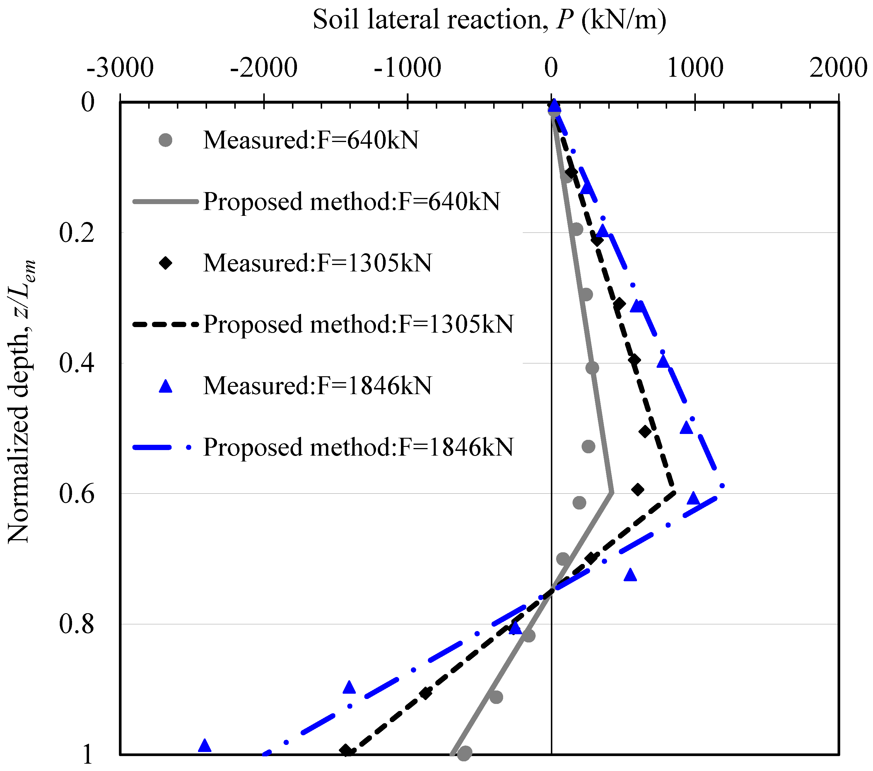
As the depth increases, the magnitude of the lateral soil reaction around a monopile generally increases to a maximum value and then decreases to zero at the depth of the rotation point, and following that, at the rear side of the monopile, it gradually increases from this rotation point to a maximum value at the pile tip (e.g., Prasad and Chari, [30]; Zhang et al. [17]; Li et al. [18]; Wang et al. [15]). The maximum soil lateral reaction in the front side is located at a depth of Zm.
(2)
The maximum soil lateral pressure in the front side of the monopile is pm, which may be calculated using Rankine’s passive earth pressure theory (KpγZm) and the mobilization coefficient of ultimate soil resistance η, where γ′ is the effective unit weight of soil, and Kp is the coefficient of Rankine’s passive earth pressure. The mobilization coefficient η is introduced to quantify the amount of soil pressure/reaction mobilized under a certain loading magnitude. At a given depth of the monopile, to account for the non-uniformity distribution of soil lateral pressure across the diameter of a circular monopile, a reduction factor of 0.8 is usually introduced (e.g., Zhang et al. [17]; Prasad and Chari [30]).
(3)
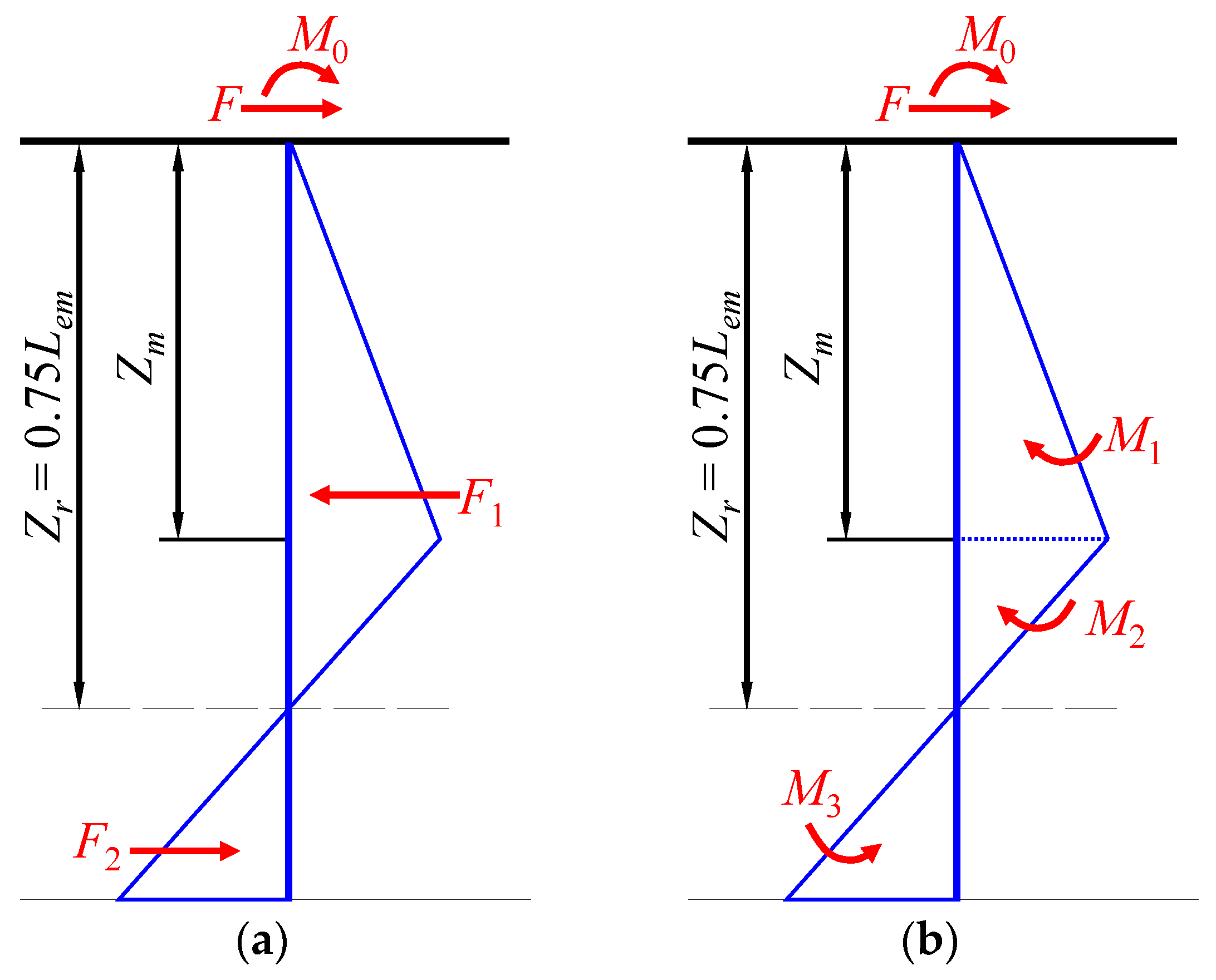
According to the equilibrium of lateral force and moment on the monopile, the depth of the maximum soil pressure Zm in front of the monopile can be determined using Equation (1), while the correlation between the applied lateral load and the mobilization coefficient η is given by Equation (2). The derivation process of Equations (1) and (2) can be referred to Appendix A. Equation (1) demonstrates that the depth of the maximum soil pressure Zm is only related to the pile embedded depth Lem and load eccentricity Lup, and it is independent of the magnitude of the applied lateral load F, which is in line with the findings by other researchers (e.g., Georgiadis et al. [21]; Zhu et al. [27]; Prasad and Chari [30]).
Z m = 0.09 L u p 2 + 0.0132 L e m 2 + 0.08 L u p L e m 0.3 L u p 0.2
η = F Z m K p γ L e m D ( 0.3 0.025 L e m 0.75 L e m Z m )

2.3. Correlation between Pile Head Rotation and Mobilization Coefficient

The magnitude of mobilized soil lateral reaction depends on the applied load, as illustrated in Equation (2); therefore, it can be inferred that the pile deformation is directly related to the applied load, and a correlation between mobilization coefficient η and pile lateral deformation (e.g., pile head rotation θ) should exist. In this study, results measured from a series of rigid pile loading tests have been employed to back-analyze this correlation. These piles, embedded in different types of cohesionless soils of varying density and with a wide range of dimensions, were loaded monotonically. The details of these pile tests are summarized in Table 2.
To derive the correlation between mobilization coefficient η and pile head rotation θ from the measured response on each test pile, three steps need be followed.
Firstly, for a specifically applied lateral load Fi, the mobilization coefficient ηi is calculated using Equations (1) and (2). Secondly, the pile head rotation θi or lateral displacement yi corresponding to this applied load Fi can be read from the measured pile head response. If only yi is given, the pile head rotation θi can be calculated using Equation (3), as shown in Figure 3. It should be noted that Equation (3) is based on assumptions that the test pile is 100% rigid and the depth of the rotation point Zr is a constant value of 0.75Lem. Then, the mobilization coefficient ηi and pile head rotation θi under the applied lateral load Fi are derived.
θ i = arctan ( y i L u p + 0.75 L e m )
It should be noted that, as the monopile is assumed as an absolutely rigid pile in this study, the translational and bending deformations are neglected for the computation of pile head displacement, and the proposed method is only suitable for the piles in which the translational and bending deformations can be ignored. For sites with loose or over-consolidated sand, the pile translational or bending deformation cannot be neglected, and the application of the proposed method should be examined carefully.
By repeating these steps above, the correlation between η and θ is derived for each test pile, which is shown in Figure 4:
(1)
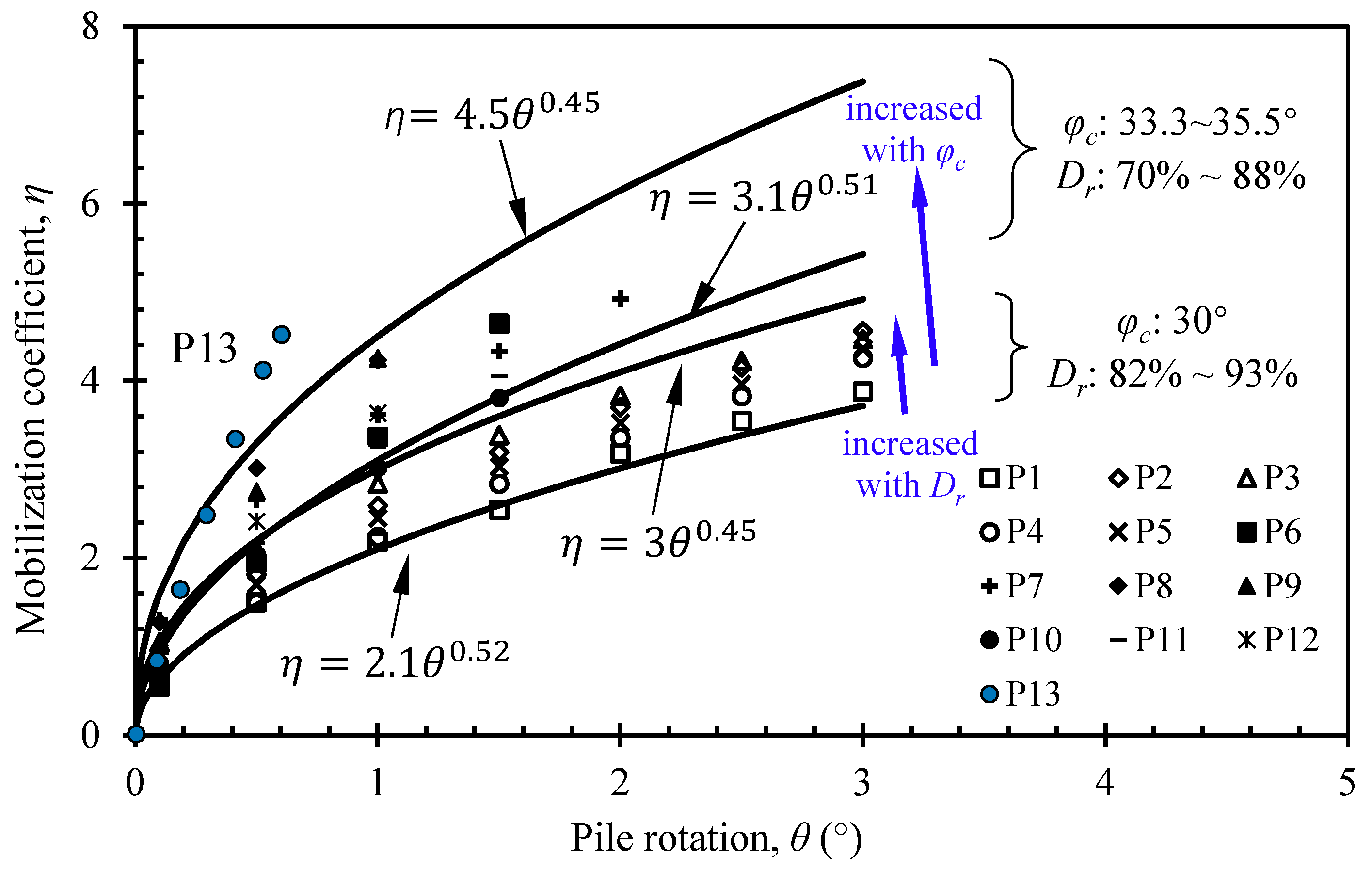
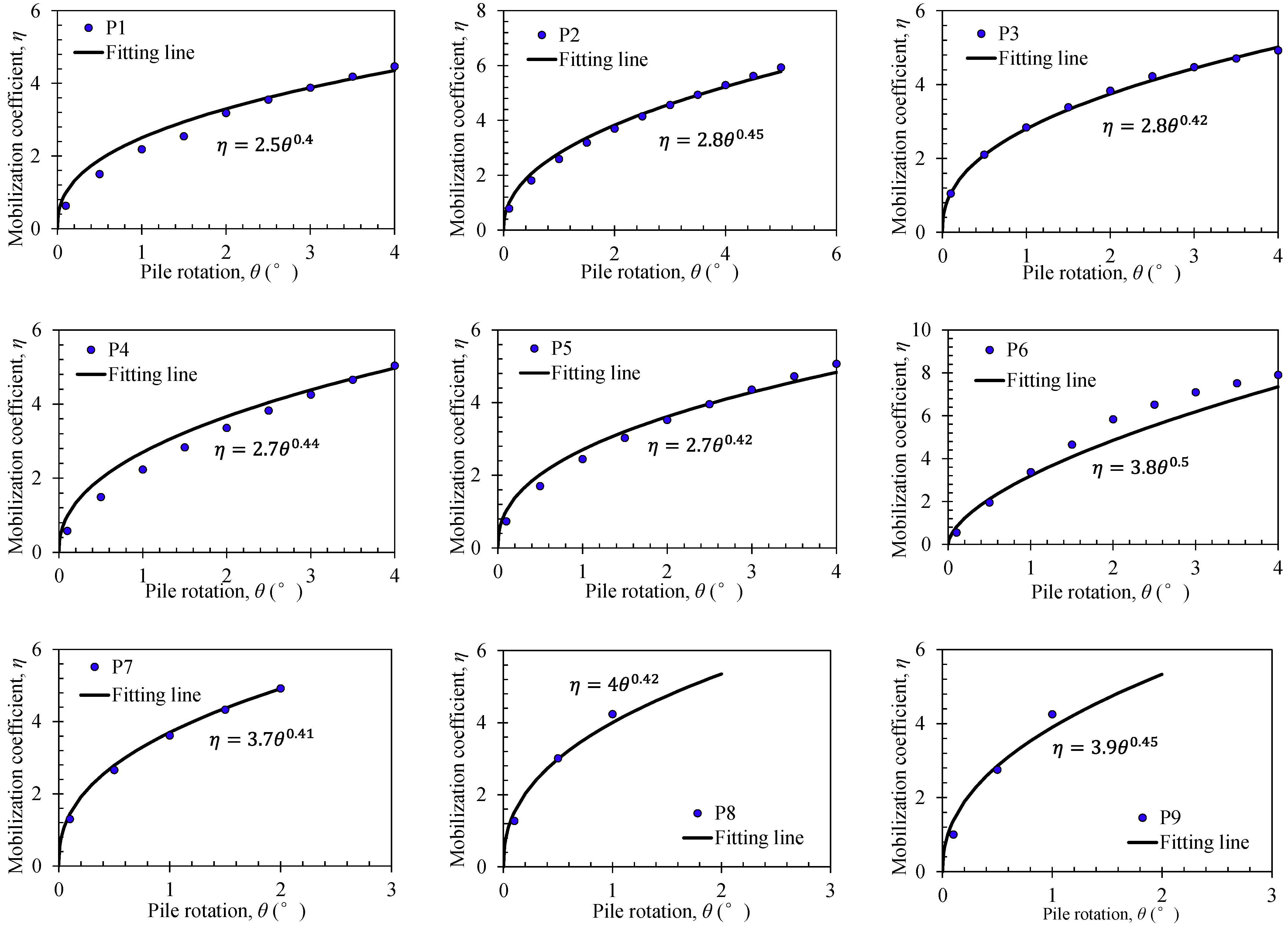
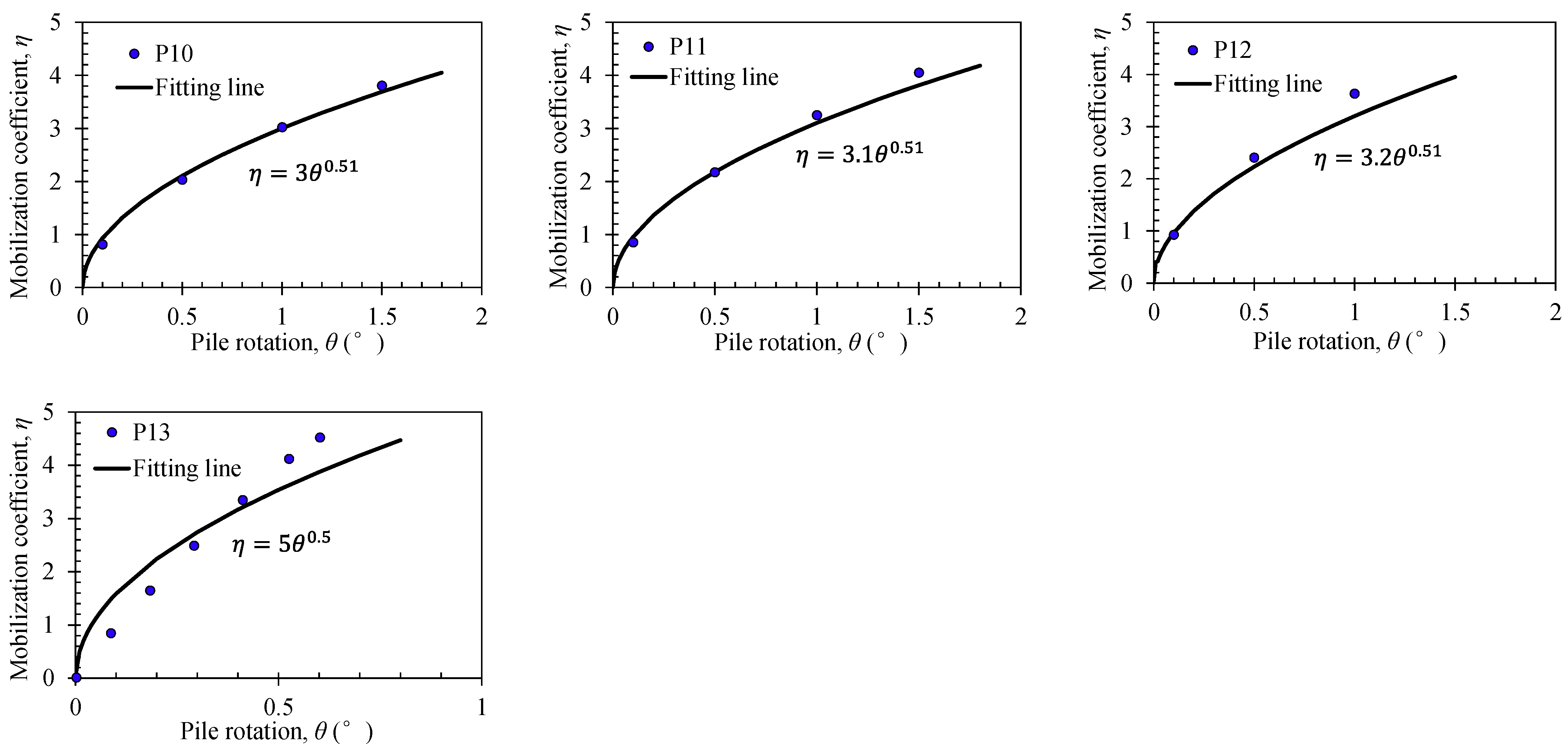
As expected, the value of mobilization coefficient η increases with pile head rotation θ in a nonlinear pattern.
(2)
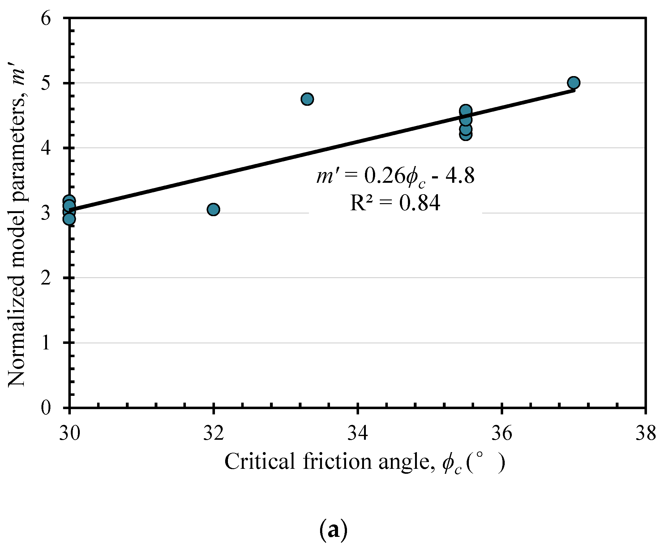
The relationship between η and θ depends on the critical friction angle of soil ϕc and the relative density Dr, i.e., piles in similar ground conditions generate nearly identical ηθ correlations.
(3)
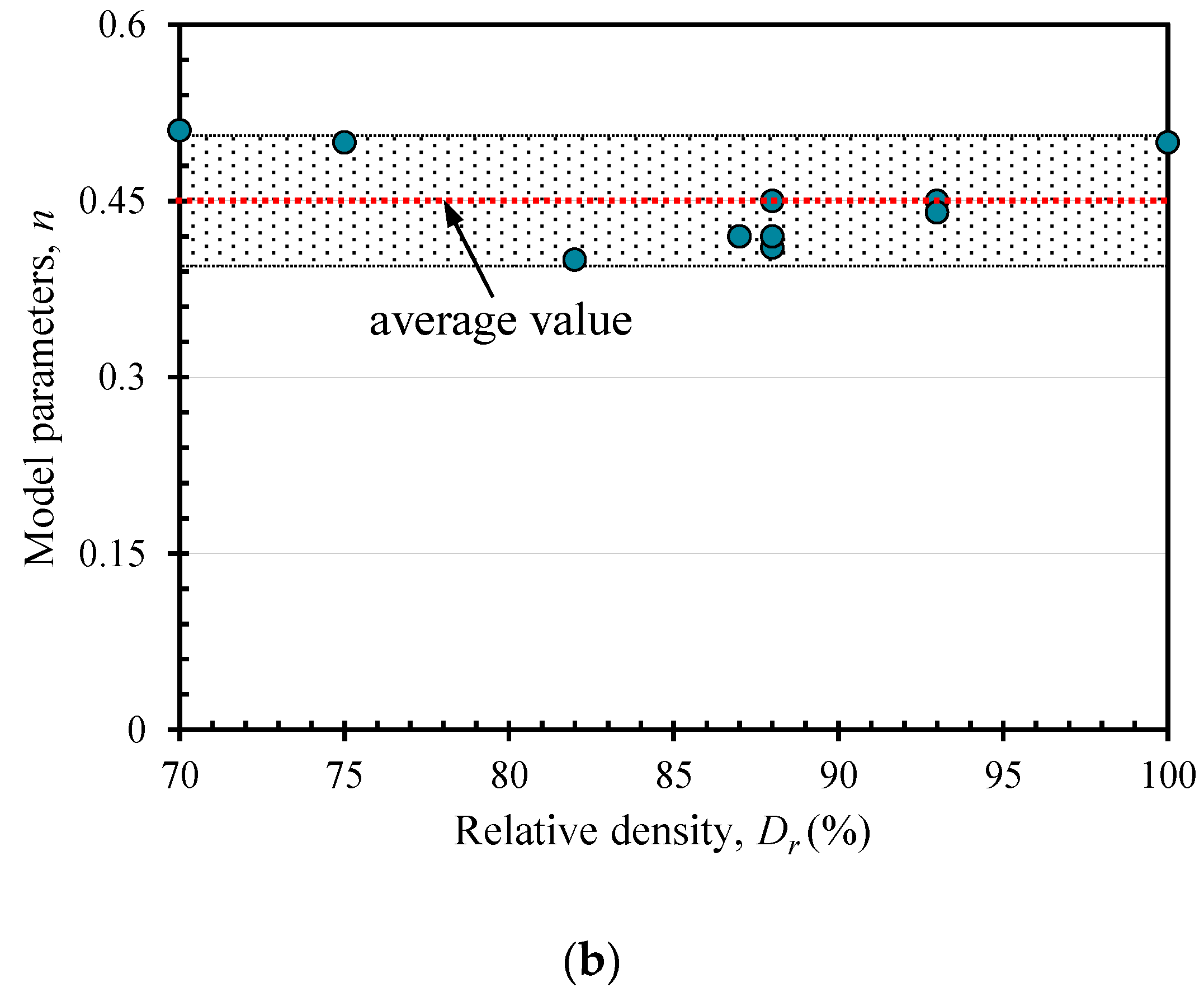
A power function, as shown in Equation (4), is capable of modeling the relationship between η and θ, where m and n are the model parameters.
η = m θ n
To investigate the variation patterns of model parameters m and n with the sand critical friction angle ϕc and relative density Dr, the power function for each pile case is presented, as shown in Figure 5. To establish a design formula or chart for the determination of model parameters, the normalized model parameters m′ and n are plotted with sand critical friction angle ϕc and relative density Dr, respectively, as shown in Figure 6. The normalized model parameter m′ is defined as m′ = m/Dr, in which m is the model parameter illustrated in Equation (4) and Dr is the sand relative density.
As shown in Figure 6a, the normalized model parameter m′ generally increases linearly with the sand critical friction angle ϕc, which indicates that the higher the critical friction angle, the stiffer the load-deformation response will be. As the relative density Dr is incorporated into the normalized model parameter m′, a higher relative density will induce a larger model parameter m, which agrees the observations in practical pile tests [27]. As shown in Figure 6b, the model parameter n is mainly located in the range of 0.4~0.5 and is irrelevant to the sand relative density Dr. Based on the cases analyzed, an average value of n = 0.45 is employed in this study.
As highlighted by Li et al. [3] for short rigid monopiles, the contribution of factors such as base shear and side shear stress becomes increasingly important. Although the contribution of these factors is not directly considered in the presented model, it should be pointed out that, however, as the correlation between pile head rotation and mobilization coefficient are back-analyzed from the measured pile head responses of the pile loading tests, the contribution of base shear and side shear stress has been indirectly incorporated into the model.

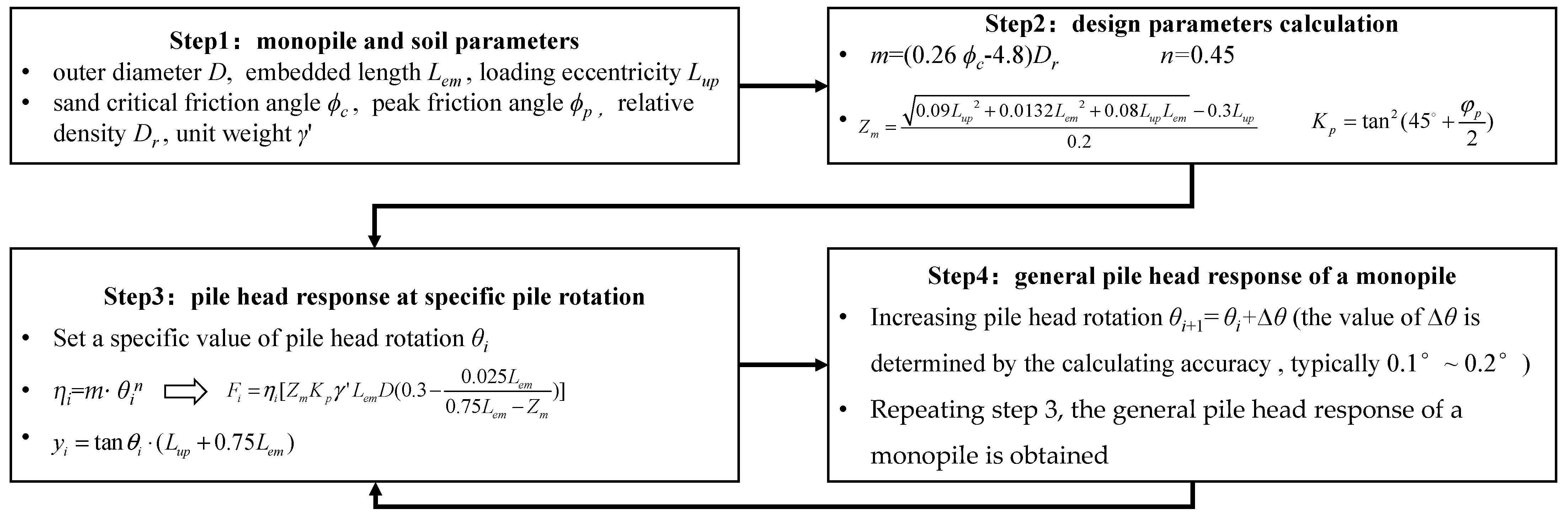
2.4. General Design Procedures

The following procedures are recommended for a laterally loaded rigid monopile in cohesionless soil, and the flow chart for calculating the load-displacement response of monopiles is illustrated in Figure 7.
  • Set a specific value of pile head rotation θi;
  • According to the ground conditions, including the sand critical friction angle ϕc and relative density Dr, the value of mobilization coefficient ηi can be calculated using Equation (4), where m = (0.26 ϕc − 4.8)Dr; n = 0.45.
  • Calculate the corresponding pile head load Fi using Equation (5), as well as the pile head displacement using Equation (6).
  • Repeating steps 1 to 3, the general pile head response of a monopile can be estimated.
F = η [ Z m K p γ L e m D ( 0.3 0.025 L e m 0.75 L e m Z m ) ]
y i = tan θ i ( L u p + 0.75 L e m )

3. Validation

3.1. Database

A database consisting of 23 pile tests is compiled from the published literature to verify the proposed design approach. The diameter of these test piles is up to 3 m in prototype scale, which were tested in centrifuge facilities, and the slenderness ratio ranges from 3 to 10. The load eccentricity is in the range of (0.92~15)D. The cohesionless soil consists of medium or dense sand with an estimated critical friction angle value of 30°~35°. A detailed description of the compiled database is presented in Table 3.

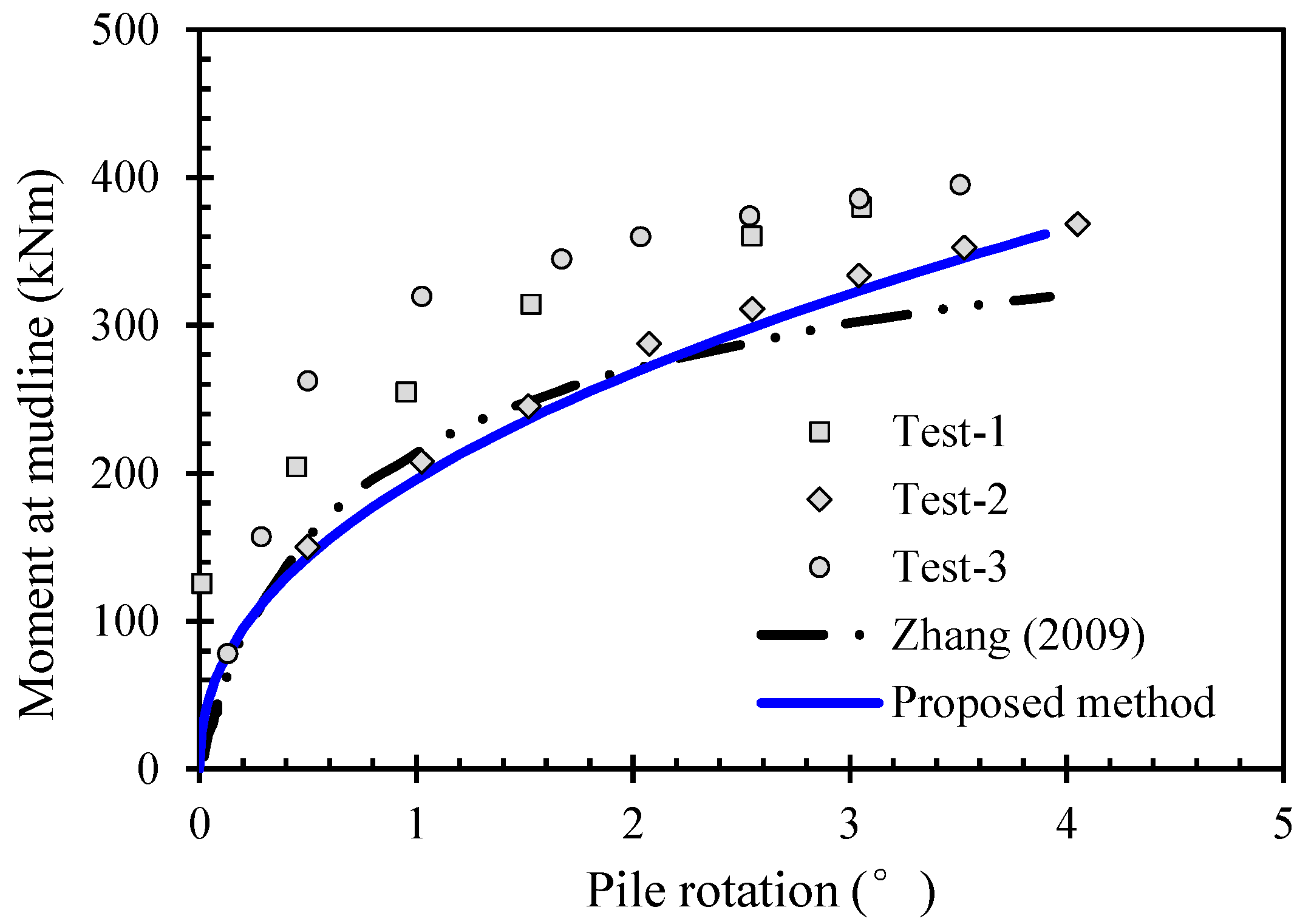
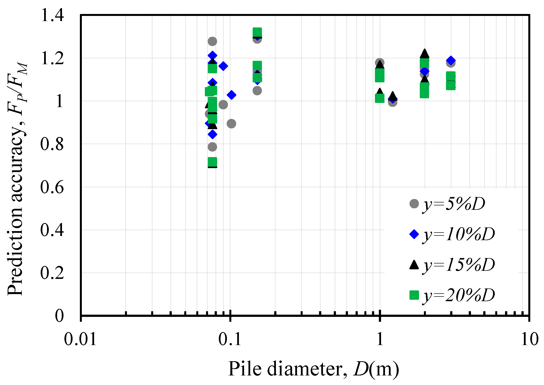
3.2. Pile Head Response

To verify the moment-rotation response of the pile head, centrifuge model tests reported by Nazir [36] are adopted. In total, 3 centrifuge tests with different accelerations are performed to model an identical pile with a diameter of 1 m and embedded length of 2 m in prototype scale, i.e., Test 1: acceleration = 50 g, diameter of model pile is 20 mm; Test 2: acceleration = 40 g, diameter of model pile is 25 mm; Test 3: acceleration = 33.3 g, diameter of model pile is 30 mm. The load eccentricity is 6 times the pile outer diameter. These tests are carried out in dry dense Erith sand, and the unit weight is 16.4 kN/m3, corresponding to a relative density of 85%. Studies performed by Dickin and King [38], Laman et al. [39] and Dickin and Laman [40] on Erith sand show that:
(4)
Erith sand consists of pure quartz grains with subrounded shape with critical friction angle ϕc of 35° [40].
(5)
The peak friction angle ϕp of Erith sand can be determined according to Equation (7).
ϕ p = 46.1 ° 2.06 ° ln ( σ 3 101 )
where σ3 is the confining pressure in kPa.
To analyze the prototype pile behavior using the proposed method, the peak friction angle ϕp of the sand in the centrifuge tests should be first determined. For simplicity, the peak friction angle is assumed to be constant within the depth of the pile, and the representative depth is 0.5Lem. For sand at a depth of 0.5Lem, the average stress σave = 9.8 kPa (the coefficient of lateral earth pressure is assumed as 0.4). Thus, based on Equation (7), the peak friction angle ϕp can be determined as 51°, which is used to determine the coefficient of Rankine’s passive earth pressure (Kp).
During the tests, the pile head rotation θ is recorded under various load magnitudes, and the measured moment-rotation data from the three centrifuge tests are employed to verify this study’s proposed design. According to the critical friction angle ϕc and relative density Dr of Erith sand, the correlation between η and θ adopted in this study is η = 3.7θ0.45. As shown in Figure 8, the proposed design method agrees well with the measured pile head response, which demonstrates the validity of the proposed design method. In addition, the prediction given by Zhang [6] is also shown in Figure 8, and the proposed method in this paper agrees well with the lower boundary of the measured results and those obtained by Zhang’s method. The proposed method is slightly better than Zhang’s [6] when the pile rotation angle is larger than 2º. Comparing the computing efficiency, this study’s proposed design is more convenient and does not need computer-based modeling and analysis.
To further verify the reliability of the proposed design procedures, the measured pile head load-displacement responses from 23 piles in Table 3 are analyzed. Detailed information for each test pile and the corresponding ground conditions are summarized in Table 3. For clarity, only loads corresponding to pile head displacements of y = 5%D, 10%D, 15%D, and 20%D are compared between measured and predicted values, which are shown in Figure 9. The vertical coordinate is the load ratio of predicted to measured Fp/Fm, and the abscissa is the outer diameter of each test pile. Fp is the predicted load calculated by the proposed method, and Fm is the measured load in the collected case history. It can be seen from Figure 9 that the recommended design procedures generally produce relatively good predictions for these test piles. The load ratio between measured and predicted is mainly within 0.8~1.2. The η–θ relationship adopted in this study is based on the critical friction angle ϕc and relative density Dr of the soil conditions, and the specific η–θ correlation for each test pile is listed in Table 3. In addition, as shown in Figure 9, Fp tends to be larger than Fm in general, and the reason may be due to the fact that the bending of the pile is ignored in the proposed method. When pile bending is considered, it will result in greater pile head deformation with the same pile rotation angle. In other words, ignoring the bending of the monopile will overestimate the pile rotation angle under the same pile head deformation, which will lead to overestimation of the soil resistance around the pile, making the predicted value higher than the measured value.

3.3. Soil Lateral Reaction Profile

To further verify the soil lateral reaction profile proposed in this study, soil lateral reaction profiles measured by Georgiadis et al. [21] are employed. In Georgiadis’s centrifuge tests, three lateral loading tests were performed on piles with diameters ranging from 1.09 m to 1.23 m in prototype scale, and the soil lateral reaction profile for a pile with a diameter of 1.224 m is illustrated in the literature. The ground model is prepared with uniform fine-grained sand under dry conditions. The relative density is about 60% and in a medium-dense state. The measured and predicted soil lateral reaction profiles of the test pile are plotted in Figure 10, which shows that the predictions given by this study’s proposed design procedures agree well with the profile measured in the test. A good agreement of pile rotation depth is also shown between the measured and assumed values in this study. This agreement proves the validity of this study’s recommended design procedures.

4. Conclusions

A semi-analytical design method for laterally loaded rigid monopiles in cohesionless soil has been presented in this paper, which can be applied without computer-based modeling and analysis. This method has been developed on the basis that the soil reaction along the monopile’s embedded length is linearly distributed, and the rotation point is located at a depth of 0.75Lem, which has been validated by a series of field or laboratory tests results. In this method, mobilization coefficient η is introduced to quantify the magnitude of soil lateral reaction mobilized under a certain load. The correlation between coefficient η and pile head rotation θ is derived by back-analyzing measured results from 13 test piles reported in the published literature. Furthermore, it was found that the parameters in Equation (4) are related to the critical friction angle ϕc and relative density Dr of cohesionless soils. The normalized model parameter m′ generally increases linearly with the sand critical friction angle ϕc, while the model parameter n is mainly located in the range of 0.4~0.5 and is irrelevant to the sand relative density Dr, based on the cases analyzed.
The proposed design method has been verified against measurements from another 23 test piles compiled in a database, which showed that this method generally produces a good prediction of pile head response, especially for larger diameter monopiles. Furthermore, comparison of a measured soil reaction profile against one calculated by the proposed design method proves the validity of the assumed soil reaction profiles.
It should be noted that as the mobilization coefficient is back-analyzed from piles mostly embedded in uniform ground, the pile bending and translational deformations are neglected in this study. The back-analyzed mobilization coefficient needs to be examined using more rigorous and theoretical methods in the future. In addition, for sites with loose or over-consolidated sand, the pile translational or bending deformation cannot be neglected, and the application of the proposed method should be carefully examined.

Author Contributions

Conceptualization, R.L. and A.W.; methodology, R.L. and J.L.; validation, J.L. and A.W.; formal analysis, J.L. and A.W.; investigation, R.L. and W.D.; writing—original draft preparation, R.L.; writing review and editing, R.L., A.W. and B.Z.; visualization, R.L. and W.D.; supervision B.Z.; funding acquisition, R.L. and A.W. All authors have read and agreed to the published version of the manuscript.

Funding

The authors acknowledge the funding received from the National Natural Science Foundation of China (52208343, 52168047), Natural Science Foundation of Jiangsu Province of China (BK20210051), and Natural Science Foundation of Jiangxi Province (20232BAB214078) for supporting this research.

Institutional Review Board Statement

Not applicable.

Informed Consent Statement

Not applicable.

Data Availability Statement

Data are contained within the article.

Conflicts of Interest

Author Anhui Wang was employed by the company China Construction Industrial & Energy Engineering Group Co., Ltd.; Author Wenyun Ding was employed by the company Kunming Survey, Design and Research Institute Co., Ltd. Of CREEC. The remaining authors declare that the research was conducted in the absence of any commercial or financial relationships that could be construed as a potential conflict of interest.

Notation

Douter diameter of pile
Drrelative density of sand
Epelastic modulus of pile
Flateral force acted on pile head
Fupile ultimate load capacity
hheight of displacement measured
Kpcoefficient of Rankine’s passive earth pressure
Lemembedded length of pile
Luploading eccentricity of pile
M0moment acted on pile head
m, nparameters of correlation between η and θ
mnormalized model parameter
nhconstant of horizontal subgrade reaction
Plateral soil reaction
pmmaximum soil pressure in the front side of monopile
ylateral displacement of rigid pile
Zmdepth of maximum lateral soil reaction
Zrdepth of rotation point
ϕccritical friction angle of sand
ϕppeak friction angle of sand
γeffective density of sand
θrotation of pile
ηmobilization coefficient of ultimate soil resistance
Qbnormalized load magnitude

Appendix A. Derivation of Mobilization Coefficient η

Figure A1. Schematic force diagrams of rigid monopile: (a) horizontal force equilibrium; (b) moment equilibrium.
Jmse 12 00208 g0a1
Prasad et al. [30] introduced a reduction factor of 0.8 to account for non-uniform soil reaction distribution across the pile diameter. In the present analysis, a reduction factor of 0.8 is also introduced in the proposed method. Based on the soil pressure distribution profile proposed in Section 2.2, the horizontal forces acting on the pile are illustrated in Figure A1a, and can be expressed as follows:
F 1 = 1 2 × ( 0.8 η K p γ Z m × 0.75 L e m ) × D = 0.3 η K p γ Z m L e m D
F 2 = 1 2 × 0.25 L e m × 0.8 η K p γ Z m 0.75 L e m Z m × 0.25 L e m D = 0.025 L e m 2 D × η K p γ Z m 0.75 L e m Z m
The horizontal force equilibrium yields:
0.3 η K p γ Z m L e m D = F + 0.025 L e m 2 D × η K p γ Z m 0.75 L e m Z m
The moments acted on the rigid monopile are illustrated in Figure A1b, and can be expressed as follows:
M 1 = 4 15 η K p γ D Z m 3
M 2 = 2 × ( 0.75 L e m Z m ) × ( 0.75 L e m + 2 Z m ) × Z m 15 × η K p γ D
M 3 = 0.025 L e m 2 D × η K p γ Z m 0.75 L e m Z m × 11 12 L e m = 0.0229 L e m 3 D × η K p γ Z m 0.75 L e m Z m
The moment equilibrium of the pile at the ground line yields:
M 0 = F × L u p = 0.0229 L e m 3 D × η K p γ Z m 0.75 L e m Z m 4 15 η K p γ D Z m 3 2 × ( 0.75 L e m Z m ) × ( 0.75 L e m + 2 Z m ) × Z m 15 × η K p γ D
By solving Equations (A3) and (A7), the depth of the maximum soil reaction Zm and the coefficient of earth pressure η can be obtained:
Z m = 0.09 L u p 2 + 0.0132 L e m 2 + 0.08 L u p L e m 0.3 L u p 0.2
η = F Z m K p γ L e m D ( 0.3 0.025 L e m 0.75 L e m Z m )

References

  1. Poulos, H.G.; Hull, T.S. The role of analytical geomechanics in foundation engineering. In Foundation Engineering: Current Principles and Practices; ASCE: Reston, VA, USA, 1989; pp. 1578–1606. [Google Scholar]
  2. Tomlinson, M.; Woodward, J. Pile Design and Construction Practice; Taylor & Francis: London, UK; New York, NY, USA, 2015. [Google Scholar]
  3. Li, W.; Zhu, B.; Yang, M. Static Response of Monopile to Lateral Load in Overconsolidated Dense Sand. J. Geotech. Geoenviron. Eng. 2017, 143, 04017026. [Google Scholar] [CrossRef]
  4. Yang, M.; Luo, R.; Li, W. Numerical study on accumulated deformation of laterally loaded monopiles used by offshore wind turbine. Bull. Eng. Geol. Environ. 2018, 77, 911–921. [Google Scholar] [CrossRef]
  5. Luo, R.; Hu, M.; Yang, M.; Li, W.; Wang, A. Static Design for Laterally Loaded Rigid Monopiles in Cohesive Soil. J. Mar. Sci. Eng. 2023, 11, 817. [Google Scholar] [CrossRef]
  6. Zhang, L. Nonlinear analysis of laterally loaded rigid piles in cohesionless soil. Comput. Geotech. 2009, 36, 718–724. [Google Scholar] [CrossRef]
  7. Motta, E. Lateral deflection of horizontally loaded rigid piles in elastoplastic medium. J. Geotech. Geoenviron. Eng. 2013, 139, 501–506. [Google Scholar] [CrossRef]
  8. Reese, L.C.; Cox, W.R.; Koop, F.D. Analysis of Laterally Loaded Piles in Sand. In Proceedings of the Offshore Technology Conference, Houston, TX, USA, 6–8 May 1974; pp. 95–105. [Google Scholar]
  9. Kozubal, J.; Puła, W.; Wyjadłowski, M.; Bauer, J. Influence of varying soil properties on evaluation of pile reliability under lateral loads. J. Civ. Eng. Manag. 2013, 19, 272–284. [Google Scholar] [CrossRef]
  10. Ashour, M.; Norris, G.; Pilling, P. Lateral loading of a pile in layered soil using the strain wedge model. J. Geotech. Geoenviron. Eng. 1998, 124, 303–315. [Google Scholar] [CrossRef]
  11. Higgins, W.; Vasquez, C.; Basu, D.; Griffiths, D.V. Elastic solutions for laterally loaded piles. J. Geotech. Geoenviron. Eng. 2012, 139, 1096–1103. [Google Scholar] [CrossRef]
  12. Suryasentana, S.; Lehane, B. Numerical derivation of CPT-based py curves for piles in sand. Géotechnique 2014, 64, 186–194. [Google Scholar] [CrossRef]
  13. Abdel-Rahman, K.; Achmus, M. Finite element modelling of horizontally loaded monopile foundations for offshore wind energy converters in Germany. In International Symposium on Frontiers in Offshore Geotechnics; Cassidy, M., Gourvenec, S., Eds.; Taylor & Francis: Perth, Australia, 2015; pp. 391–396. [Google Scholar]
  14. Hu, Q.; Han, F.; Prezzi, M.; Salgado, R.; Zhao, M. Lateral load response of large-diameter monopiles in sand. Géotechnique 2022, 72, 1035–1050. [Google Scholar] [CrossRef]
  15. Wang, H.; Lehane, B.M.; Bransby, M.F.; Wang, L.Z.; Hong, Y.; Askarinejad, A. Lateral behavior of monopiles in sand under monotonic loading: Insights and a new simple design model. Ocean. Eng. 2023, 277, 114334. [Google Scholar] [CrossRef]
  16. Brinch-Hansen, J. The Ultimate Resistance of Rigid Piles against Transversal Forces; Bulletin 12; Danish Geotechnical Institute: Copenhagen, Denmark, 1961; pp. 1–9. [Google Scholar]
  17. Zhang, L.; Silva, F.; Grismala, R. Ultimate lateral resistance to piles in cohesionless soils. J. Geotech. Geoenviron. Eng. 2005, 131, 78–83. [Google Scholar] [CrossRef]
  18. Li, W.; Gavin, K.; Doherty, P. Experimental investigation on the lateral load capacity of monopiles in dense sand. In Proceedings of the 38th Annual Conference on Deep Foundations, Phoenix, AZ, USA, 25–28 September 2013; pp. 67–75. [Google Scholar]
  19. Zhang, L.; Ahmari, S. Nonlinear analysis of laterally loaded rigid piles in cohesive soil. Int. J. Numer. Anal. Methods Geomech. 2013, 37, 201–220. [Google Scholar] [CrossRef]
  20. Murphy, G.; Doherty, P.; Cadogan, D.; Gavin, K. Field experiments on instrumented winged monopiles. Proc. Inst. Civ. Eng.-Geotech. Eng. 2016, 169, 227–239. [Google Scholar] [CrossRef]
  21. Georgiadis, M.; Anagnostopoulos, C.; Saflekou, S. Centrifugal testing of laterally loaded piles in sand. Can. Geotech. J. 1992, 29, 208–216. [Google Scholar] [CrossRef]
  22. Klinkvort, R.T.; Hededal, O. Effect of load eccentricity and stress level on monopile support for offshore wind turbines. Can. Geotech. J. 2014, 51, 966–974. [Google Scholar] [CrossRef]
  23. El Naggar, M.H.; Wei, J.Q. Response of tapered piles subjected to lateral loading. Can. Geotech. J. 1999, 36, 52–71. [Google Scholar] [CrossRef]
  24. Qin, H.; Guo, W.D. Response of static and cyclic laterally loaded rigid piles in sand. Mar. Georesour. Geotechnol. 2016, 34, 138–153. [Google Scholar] [CrossRef]
  25. Choo, Y.W.; Kim, D. Experimental Development of the py Relationship for Large-Diameter Offshore Monopiles in Sands: Centrifuge Tests. J. Geotech. Geoenviron. Eng. 2016, 142, 04015058. [Google Scholar] [CrossRef]
  26. Mu, L.; Kang, X.; Feng, K.; Huang, M.; Cao, J. Influence of vertical loads on lateral behaviour of monopiles in sand. Eur. J. Environ. Civ. Eng. 2018, 22 (Suppl. S1), 286–301. [Google Scholar] [CrossRef]
  27. Zhu, B.; Sun, Y.X.; Chen, R.P.; Guo, W.D.; Yang, Y.Y. Experimental and Analytical Models of Laterally Loaded Rigid Monopiles with Hardening py Curves. J. Waterw. Port Coast. Ocean. Eng. 2015, 141, 04015007. [Google Scholar] [CrossRef]
  28. Ahmed, S.S.; Hawlader, B. Numerical Analysis of Large-Diameter Monopiles in Dense Sand Supporting Offshore Wind Turbines. Int. J. Geomech. 2016, 16, 04016018. [Google Scholar] [CrossRef]
  29. Wang, H.; Lehane, B.; Bransby, M.; Askarinejad, A.; Wang, L.; Hong, Y. A simple rotational spring model for laterally loaded rigid piles in sand. Mar. Struct. 2022, 84, 103225. [Google Scholar] [CrossRef]
  30. Prasad, Y.V.; Chari, T. Lateral capacity of model rigid piles in cohesionless soils. Soils Found. 1999, 39, 21–29. [Google Scholar] [CrossRef] [PubMed]
  31. Chari, T.R.; Meyerhof, G.G. Ultimate capacity of rigid single piles under inclined loads in sand. Can. Geotech. J. 1983, 20, 849–854. [Google Scholar] [CrossRef]
  32. Li, W.; Igoe, D.; Gavin, K. Evaluation of CPT-based Py models for laterally loaded piles in siliceous sand. Geotech. Lett. 2014, 4, 110–117. [Google Scholar] [CrossRef]
  33. Bolton, M.D. The strength and dilatancy of sands. Géotechnique 1986, 36, 65–78. [Google Scholar] [CrossRef]
  34. Joo, J.S. Behaviour of Large Scale Rigid Model Piles under Inclined Loads in Sand. Master’s Thesis, Memorial University of Newfoundland, St. John’s, NL, Canada, 1986. [Google Scholar]
  35. Agaiby, S.W.; Kulhawy, F.H.; Trautmann, C.H. Experimental Study of Drained Lateral and Moment Behavior of Drilled Shafts during Static and Cyclic Loading; Final Report; Electric Power Research Inst.: Palo Alto, CA, USA; Cornell Univ.: Ithaca, NY, USA; Geotechnical Engineering Group: Grand Junction, CO, USA, 1992. [Google Scholar]
  36. Nazir, R.B. The Moment Carrying Capcity of Short Piles in Sand. Ph.D. Thesis, University of Liverpool, Liverpool, UK, 1994. [Google Scholar]
  37. Leth, C.T. Improved Design Basis for Laterally Loaded Large Diameter Pile. Ph.D. Thesis, Department of Civil Engineering, Aalborg University, Aalborg, Denmark, 2013. [Google Scholar]
  38. Dickin, E.; King, G. Numerical modelling of the load-displacement behaviour of anchor walls. Comput. Struct. 1997, 63, 849–858. [Google Scholar] [CrossRef]
  39. Laman, M.; King, G.; Dickin, E. Three-dimensional finite element studies of the moment-carrying capacity of short pier foundations in cohesionless soil. Comput. Geotech. 1999, 25, 141–155. [Google Scholar] [CrossRef]
  40. Dickin, E.; Laman, M. Uplift response of strip anchors in cohesionless soil. Adv. Eng. Softw. 2007, 38, 618–625. [Google Scholar] [CrossRef]
Figure 1. Deformation pattern of monopile under lateral loading.
Jmse 12 00208 g001
Figure 2. Normalized rotation depth of laterally loaded monopiles: (a) PR1~PR12; (b) PR13~PR18 (modified from Zhu et al. [27]).
Jmse 12 00208 g002aJmse 12 00208 g002b
Figure 3. Sketch of pile deformation and proposed distribution of soil lateral reaction.
Jmse 12 00208 g003
Figure 4. Relationship between pile rotation and soil resistance mobilization coefficient η.
Jmse 12 00208 g004
Figure 5. Correlation between pile rotation and soil resistance mobilization coefficient for each case.
Jmse 12 00208 g005aJmse 12 00208 g005b
Figure 6. Variation patterns of model parameters with ground conditions: (a) normalized model parameter m′; (b) model parameter n.
Jmse 12 00208 g006aJmse 12 00208 g006b
Figure 7. Flow chart for calculating the load-displacement response of monopiles.
Jmse 12 00208 g007
Figure 8. Comparison of the moment-rotation results [6].
Jmse 12 00208 g008
Figure 9. Ratio of Fp to Fm under different pile deformation criteria.
Jmse 12 00208 g009
Figure 10. Comparison of soil lateral reaction.
Jmse 12 00208 g010
Table 1. Database of test piles for rotation point determination.
Pile No.Field/
Lab
Soil
Condition
Prototype Pile DimensionsPile TypeReference
D
(m)
Lem/DLup/D
PR1FieldDense sand0.346.51.18Steel Pipe PileLi et al.
[3]
PR2FieldMedium-dense0.2456.11.63Steel Pipe PileMurphy et al.
[20]
PR3FieldMedium-dense0.2456.11.63Steel Winged Pipe PileMurphy et al.
[20]
PR4LabMedium-dense to dense1.0928.31.14Steel Pipe PileGeorgiadis et al.
[21]
PR5LabDense sand36.015Steel Pipe PileKlinkvort & Hededal
[22]
PR6LabLoose sand0.1687.11.16Steel Pipe PileNaggar & Wei
[23]
PR7LabDense sand0.03215.63.59Steel Pipe PileQin & Guo
[24]
PR8LabDense sand0.03212.53.59Steel Pipe PileQin & Guo
[24]
PR9LabDense sand65.25.5Steel Pipe PileChoo & Kim
[25]
PR10~
PR12
LabDense sand0.0488.31.04Steel Pipe PileMu et al.
[26]
PR13~
PR18
LabDense sand0.1655.56Steel Pipe PileZhu et al.
[27]
Table 2. Details of pile tests for mobilization coefficient correlation.
Pile NoPile Dimensions in PrototypeSoil PropertiesTest
Description
Height of Displacement
Measured
(m)
Reference
D(m)Lem/DLup/Dγ
(kN/m3)
ϕp
(°)
ϕc
(°)
Dr
(%)
P10.07513.3115.254632 a82Angular dry sand
1 g model test
0Chari and Meyerhof
[31]
P2161516.743.23093Dry/Saturated Fontainebleau sand,
centrifuge test
1.375Klinkvort and Hededal. [22]
P338.2510.342.5884.125
P4310.510.443.4934.125
P5312.7510.242.3874.125
P60.10261.518.34333.3 b75Well-graded angular dry sand
1 g model test
0Prasad and Chari [30]
P70.1655.5569.141.535.588Saturated Hangzhou silt sand,
1 g model test
0.99Zhu et al.
[27]
P80.495
P90.165
P108.837.4700.99
P110.495
P120.165
P130.346.51.18205437100Heavily over-consolidated
Blessington sand
0Li et al.
[32]
a: defined by the critical friction angle of silica sand [33]. b: defined by the loose condition of the test sand.
Table 3. Pile tests for design validation.
Pile No.Prototype Pile DimensionsSoil PropertiesTest DescriptionMeasured
Curves b
η~θReference
D(m)Lem/DLup/Dγ
(kN/m3)
ϕp
(°)
ϕc
(°)
Dr
(%)
10.073102.3315.141.232 a771 g model testsF-yη = 2.7θ0.45Joo
[34]
20.098.92.78
30.1028.82.75
41.2247.4116.3363060centrifuge testsF-yη = 1.8θ0.45Georgiadis et al. [21]
50.07690.9216.4241.432.9medium dense1 g model testsF-yη = 1.8θ0.45Agaiby et al.
[35]
68.641.4
7641.7
8342.3
90.15230.5341.7
10641.2
11940.9
120.0763342.3
139
1415
15 *12616.4513585centrifuge testsM-θη = 3.7θ0.45Nazir
[36]
16162.516.2433080centrifuge testsF-yη = 2.4θ0.45Leth
[37]
17842.5
181042
19261.4341.6
20840.9
211040.4
2236140.5
233839.9
a: values are determined according to silica sand [33]. b: F-y: load-displacement curve of piles; M-θ: moment-rotation curve at ground line. * including 3 centrifuge tests.
Disclaimer/Publisher’s Note: The statements, opinions and data contained in all publications are solely those of the individual author(s) and contributor(s) and not of MDPI and/or the editor(s). MDPI and/or the editor(s) disclaim responsibility for any injury to people or property resulting from any ideas, methods, instructions or products referred to in the content.

