Article

Analysis of the Reliability of Subsea Clamp Connector Based on Multiple Response Surface Methodology

1
College of Safety and Ocean Engineering, China University of Petroleum (Beijing), Beijing 102249, China
2
CNOOC Research Institute, Beijing 100028, China
*
Author to whom correspondence should be addressed.
J. Mar. Sci. Eng. 2023, 11(7), 1378; https://doi.org/10.3390/jmse11071378
Submission received: 30 May 2023 / Revised: 27 June 2023 / Accepted: 3 July 2023 / Published: 6 July 2023
(This article belongs to the Special Issue Frontiers in Deep-Sea Equipment and Technology II)

Abstract

:
The subsea clamp connector is susceptible to sealing and locking failures over its lifetime in harsh marine environments and complex loading conditions, posing a serious challenge to the safe development of subsea oil and gas fields. Accurately predicting the reliability of the subsea clamp connector under realistic and complex operating conditions is therefore an important guarantee of its safe operation. Considering the main structural characteristic parameters of the subsea clamp connector, this paper conducts a reliability analysis using finite element numerical simulation combined with multiple response surface methodology (MRSM), based on the seal failure and yield failure criteria. The applicability has been verified through the application of subsea clamp connector in the Bohai Sea. The results show that the failure probability of the system is mainly affected by the radius of the seal, the contact angle of the upper and lower flanges and internal pressure. Considering the influence of various factors, the reliability of the connector was calculated to be 98.73%, and the reliability was verified by the sealing performance test. This paper provides a practical method for the reliability analysis of the subsea clamp connector structure under the comprehensive consideration of multiple factors, and provides a new technology to ensure the safe operation of subsea oil and gas fields.

1. Introduction

With the rapid development of the world’s industry, the demand for oil and gas resources is constantly increasing, and the exploration and exploitation of offshore oil and gas has become the main development direction of the petroleum industry [1,2,3]. In the development of offshore oil and gas fields, subsea connectors are important connecting components for subsea production system, such as the Christmas tree and manifold [4]. Subsea clamp connectors (as shown in Figure 1) are widely used due to the advantages of simple structure, rapid connection, and wide applicability, and their reliability directly affects the safety of subsea oil and gas field development.
At present, research on subsea connectors is mainly focused on the theoretical relationship between the load transfer of the contact surface, the locking force and the pre-tightening force, the optimization of the sealing ring structure, and related experiments [5,6,7,8]. In terms of sealing and leakage research, Yun et al. [9] established the contact mechanics model of the metal lens-type sealing gasket at the macroscopic scale based on the Hertz theory. They also analyzed the contact characteristics between the metal lens seal and the flange structure at the microscopic scale by equivalently replacing the peak cutting coefficient of a one-dimensional sinusoidal wave. Li et al. [10] analyzed the influence of pre-tightening force, contact width, preloading compression, and operating pressure on contact stress through theoretical calculations and finite element methods. Liu et al. [11] derived a calculation expression for the size ratio of a spherical sealing groove based on the spherical structure of the connector’s sealing ring. They determined the width and depth of the groove, and used finite element methods to study the influence of different pressures and compression ratios on the sealing performance of O-ring seals from various aspects, such as von mises stress, contact pressure, and contact width of different contact surfaces.
In the field of subsea connector reliability research, the main approaches are fault tree analysis and dynamic Bayesian network analysis. Wan et al. [12] analyzed the failure modes and causes of the subsea connector drive ring, and established a fault tree model. Zhang et al. [13] obtained the failure probability magnitude of subsea connector installation through fuzzy quantitative analysis of the fault tree. Chen et al. [14] proposed a fault diagnosis method based on a three-layer dynamic Bayesian network to diagnose faults and predict failures for the mechanical structure of vertical collet subsea connectors. Torfinn et al. [15] applied structural reliability analysis (SRA) to wellhead connectors, fatigue induced by overload and plastic collapse are two failure modes to estimate the fatigue failure probability. Bhardwaj et al. [16] used the first-order second-moment method and the Monte Carlo method to evaluate the structural reliability of the pipeline system in deep water under high internal pressure and high temperature. Pang et al. [17] proposed a fuzzy Markov method that integrates risk, reliability, availability, and uncertainty analysis based on fault tree, fuzzy comprehensive evaluation, and Markov methods. The method pre-processes input fault data using fault tree and fuzzy theory to improve the reliability of the input fault data. Wang et al. [18] proposed a reliability analysis method based on a dynamic Bayesian network using the Monte Carlo simulation to evaluate the failure probability of subsea wellhead connectors during their service life. Tsai et al. [19] considered wind speed probability, fatigue strength of mast arm base, miner summation, and other uncertain factors to perform the Monte Carlo simulation and generate failure probability curve. Simon et al. [20] described a verification method for subsea pipeline maintenance to confirm that the product design meets DNV standards.
The MRSM is a reliability analysis method that can simultaneously consider two or more failure factors, and it is commonly used in reliability analysis under multi-factor coupling by establishing multiple response surface functional functions. Das et al. [21] proposed an improved response surface method and applied it to the reliability analysis of stiffened plate structures. The response surface functions are formed cumulatively so that second-order effects in the response surface are properly taken into account using acceptable computational work in the evaluation of state functions. Somdatta et al. [22] investigates moving least squares (MLSM) to construct response surface functions. The advantage of MLSM over the least square method (LSM) is that it reduces the number of iterations required to obtain the updated central point of the experimental design (DOE). The final response surface was constructed for effective structural reliability analysis. Zhang et al. [23] conducted a reliability study of aircraft engine blades using the multiple response surface method by establishing four response surface models for overall deformation, radial deformation, stress, and temperature of the blade. Lu [24] proposed a structural reliability analysis method to study the dynamic reliability of turbine disk structures. Liu et al. [25] used finite element numerical simulation combined with the multiple response surface method and the Monte Carlo method to analyze the reliability of tunnel structural systems. Zhai [26] calculated the reliability of the fan connectors according to the MRSM method.
This paper proposed an MRSM by combining the failure criterion of yield and minimum sealing ratio pressure to analyze the reliability of the subsea clamp connector under multi-factors. The proposed MRSM provides a feasible approach for the reliability prediction of subsea clamp connectors.

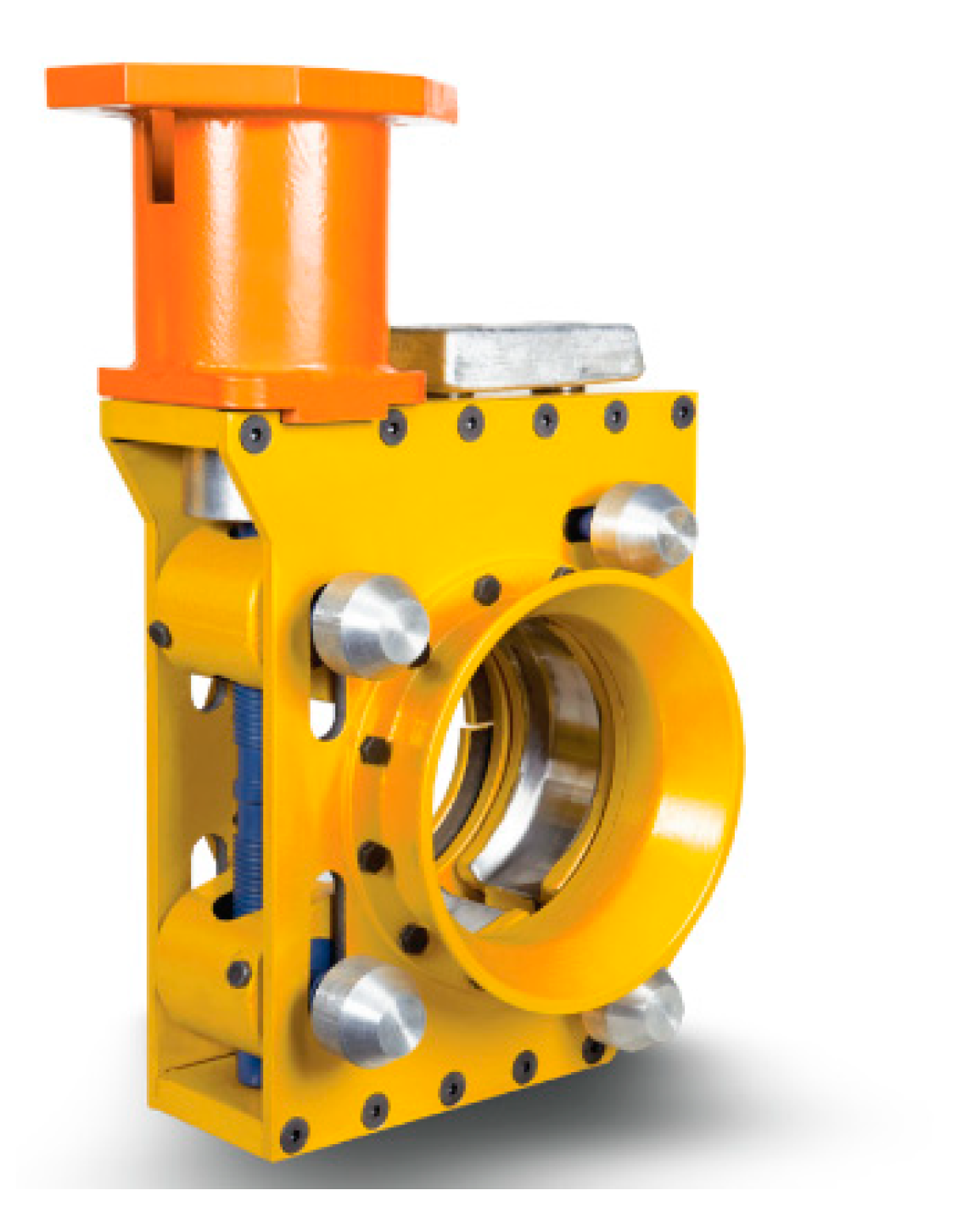
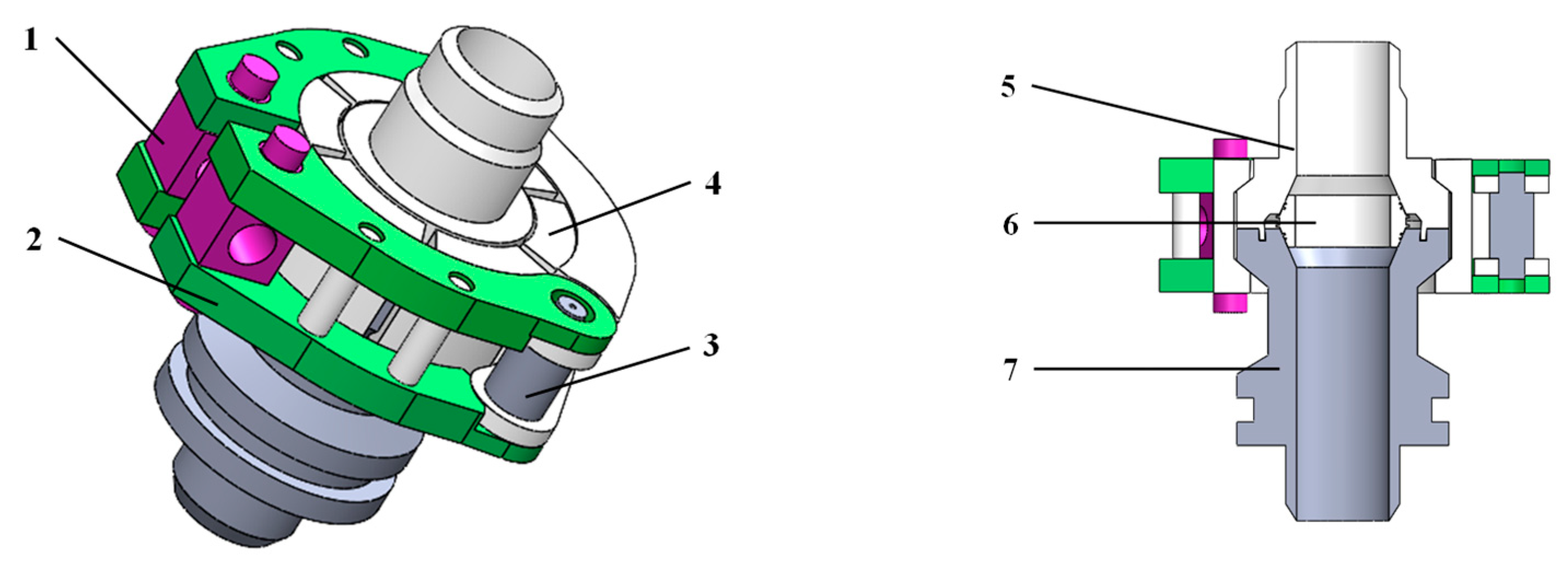
2. Structure Characteristics of Subsea Connection System

The subsea clamp connectors are mainly used to connect and fix a variety of subsea equipment, pipelines, and structural parts, including oil and gas pipelines, subsea oil wells, isolators, oil-water separators, Christmas tree, etc. The subsea clamp connector studied in the paper is a kind of structure to ensure the smooth, simple, and fast connection between the mobile end flange and the fixed end flange. It has the characteristics of simple operation, low requirements for installation environment, and reduces the influence of various uncontrollable factors. The subsea clamp connector is a rotary body axisymmetric structure, mainly including the upper flange, lower flange, clamp jaws, metal seals, and other components (as shown in Figure 2). The three-lobe clamp form makes the force of the flange more uniform. When the axial external force is applied, the overall structure is stressed evenly, and the fixed constraint and load are symmetrical along the central axis. It should maintain structural locking and sealing performance under axial force, bending moment and pressure etc.
The working condition of subsea clamp connection is very complicated. On the one hand, the sealing structure of the subsea clamp connector should play a sealing role in the internal oil and gas medium. On the other hand, the external seawater pressure caused by the water depth of the pipeline should also play a sealing role. Therefore, the lens seal and O-type composite seal (as shown in Figure 3) are commonly used in subsea clamp connectors. The metal seal is the primary seal for sealing oil and gas media, and the O-type is the secondary seal for sealing external seawater. The combination of these two sealing methods can effectively improve the reliability and service life of the seal.

3. The MRSM for Subsea Clamp Connector
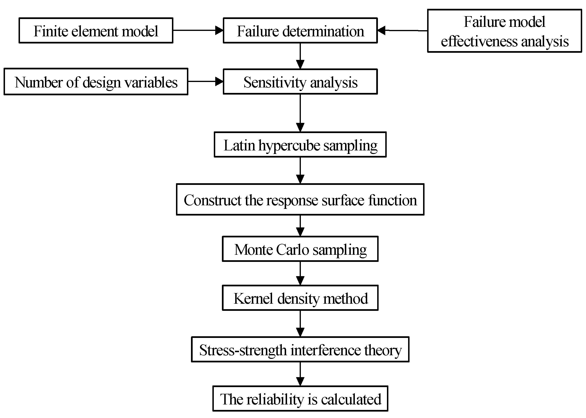
The MRSM is a reliability analysis method based on the response surface method, which can consider multiple failure factors of the system by establishing multiple response surface function functions. The response surface function is transformed into a specific mathematical polynomial expression by an implicit performance function, which can be fitted to obtain a global approximation of the output variable, and then goes to replace the true response surface while proving its correctness. The response surface function of a quadratic polynomial is often used in practical applications, and its basic expressions are as follows:
y = a 0 + i = 1 n a i x i + i = 1 n a i i x i 2 + i > 1 n a i j x i x i
The process of the newly proposed MRSM for the subsea clamp connector is shown in Figure 4 and its main steps include:
(1)
Selection of suitable failure criteria;
(2)
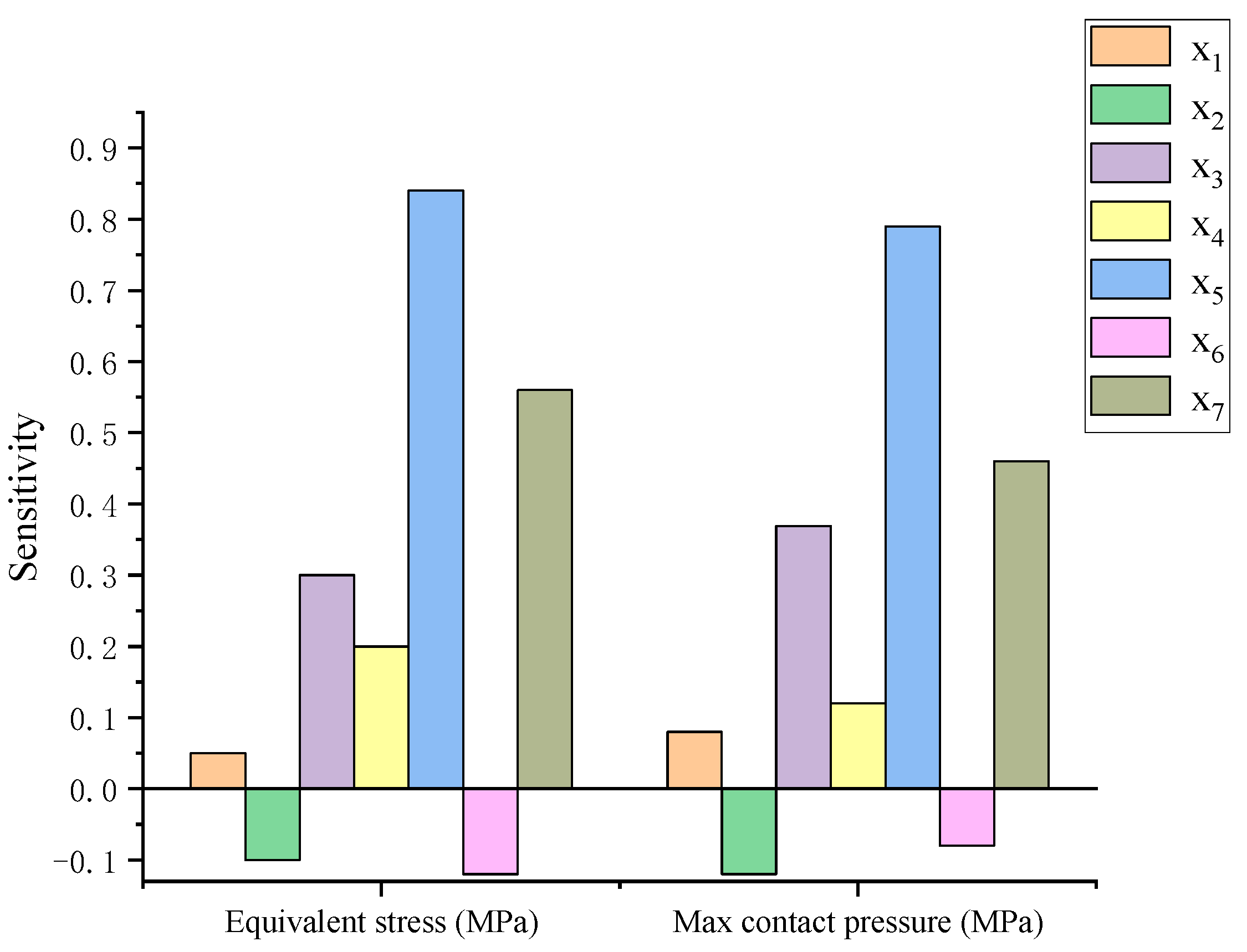
sensitivity analysis of structural parameters and internal pressure of subsea clamp connectors after parametric modeling;
(3)
acquisition of test points based on initial data using the Latin hypercube sampling method;
(4)
numerical calculations were performed on the test point data, and the response surface function was obtained by fitting the test point data and the resultant data using the least squares method;
(5)
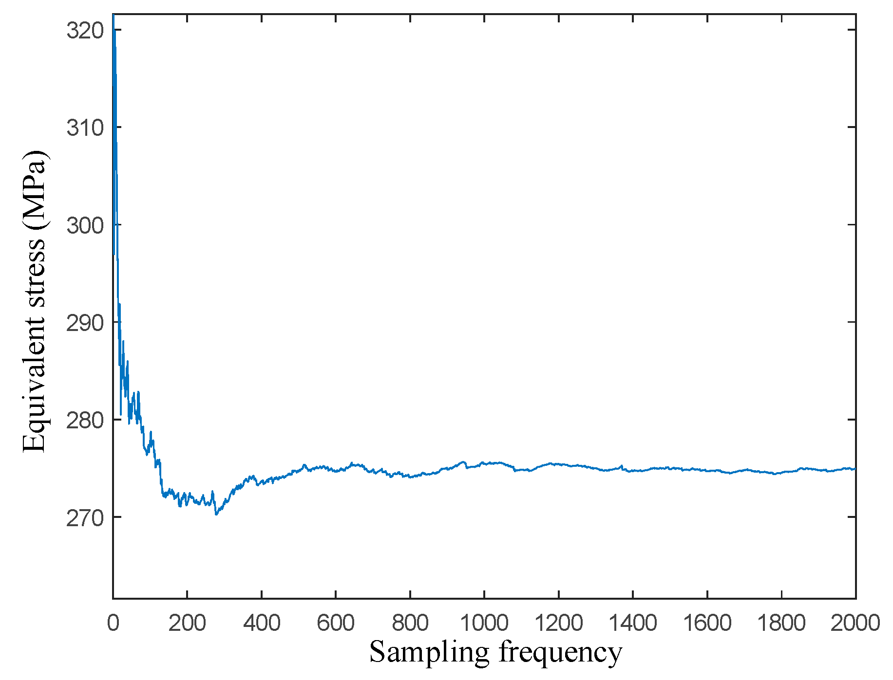
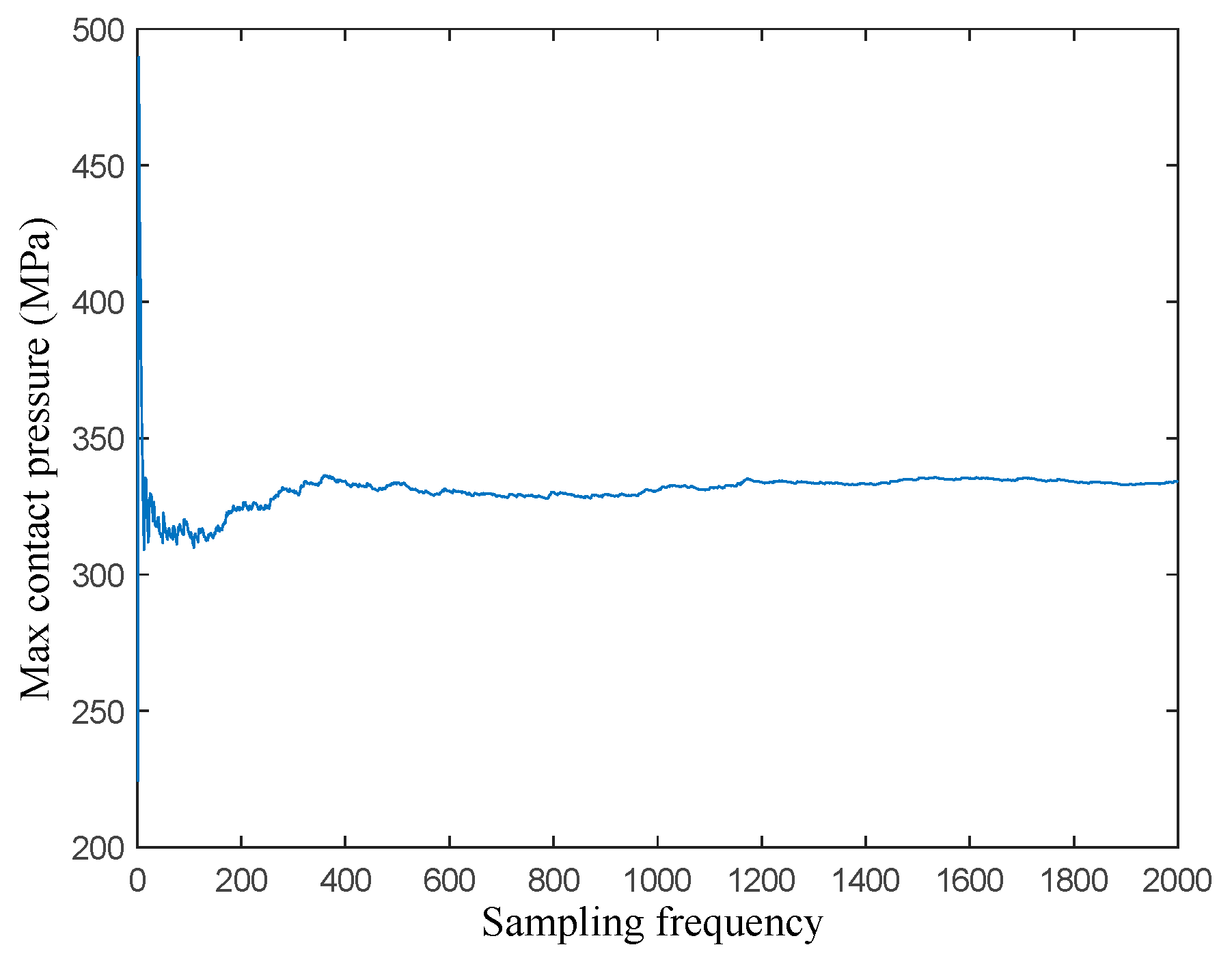
the obtained response surface function is sampled using the Monte Carlo method linkage;
(6)
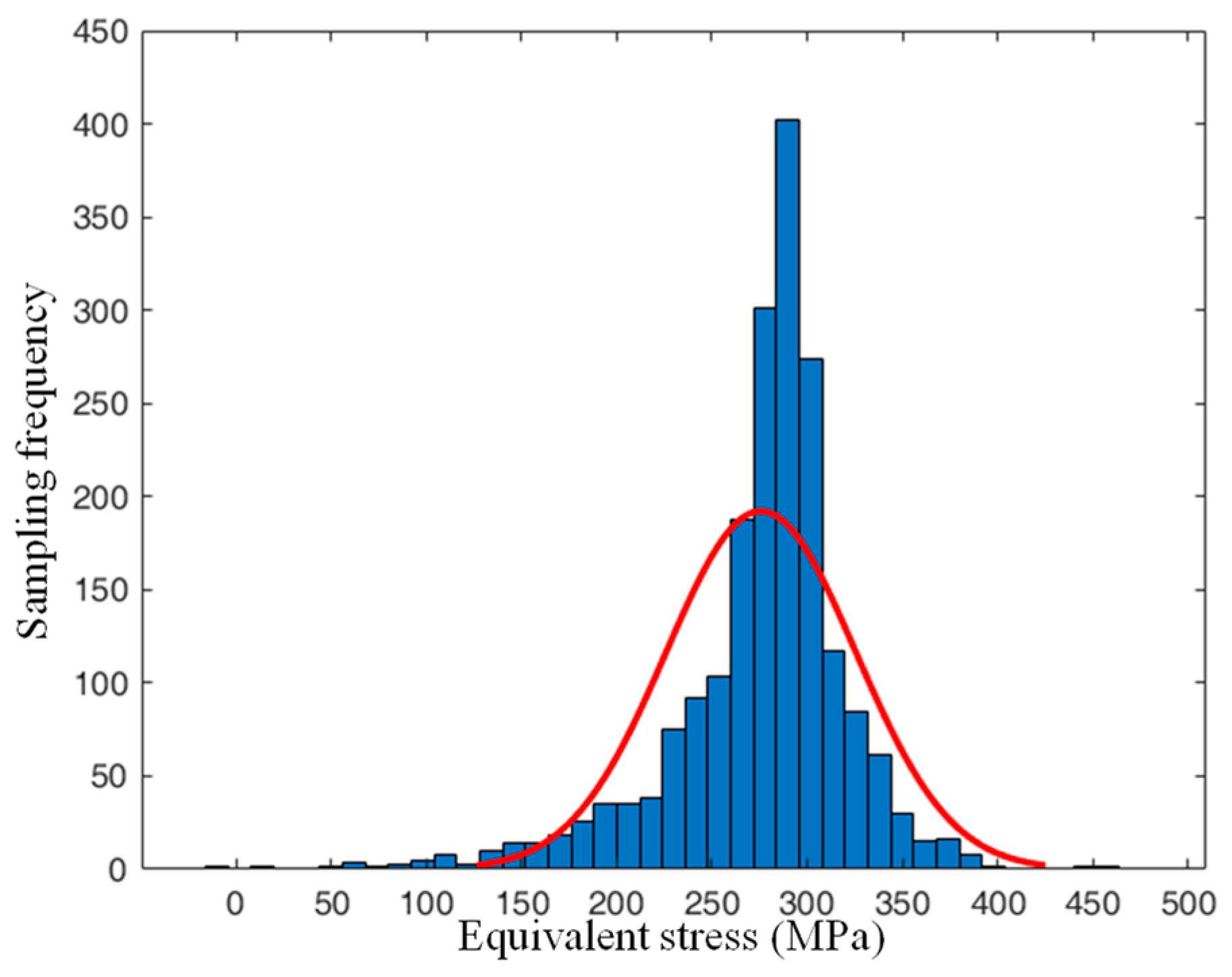
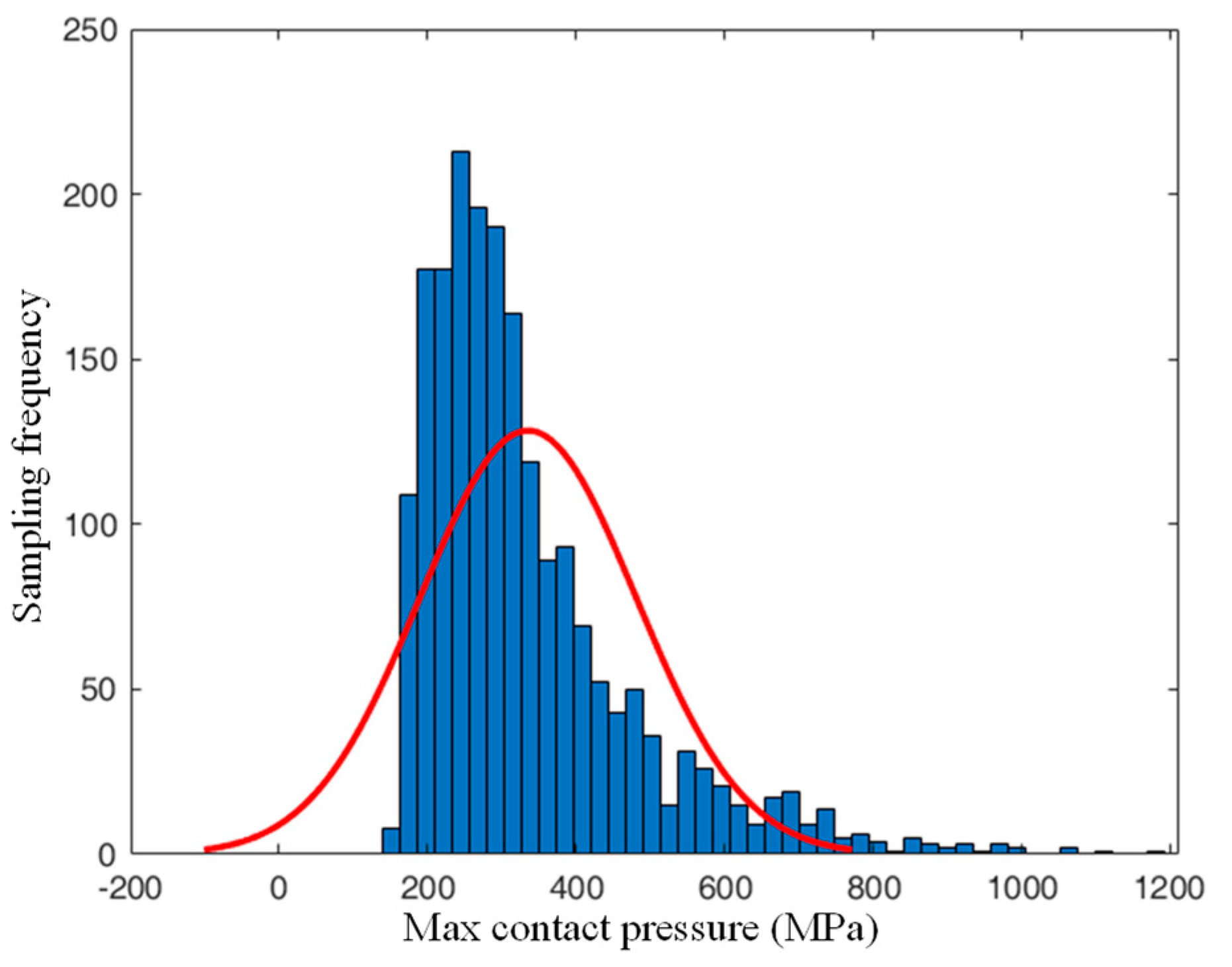
and the probability curve of the normal distribution of sample data is obtained by using the kernel density method, and finally the reliability is calculated combining the stress-strength interference theory.

3.1. Reliability Failure Criteria

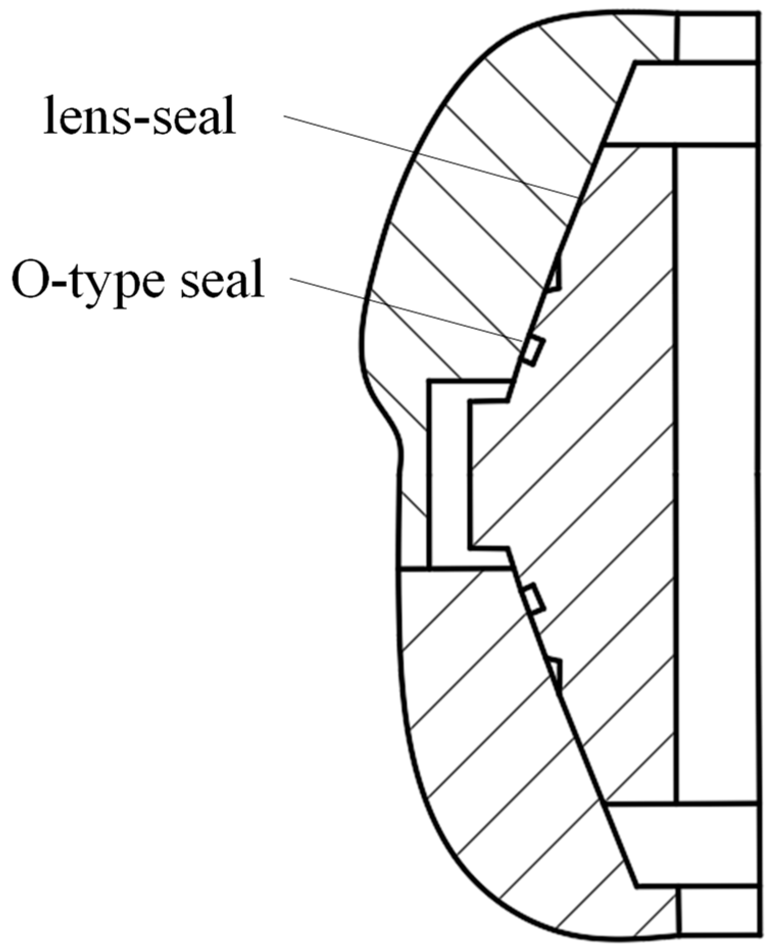
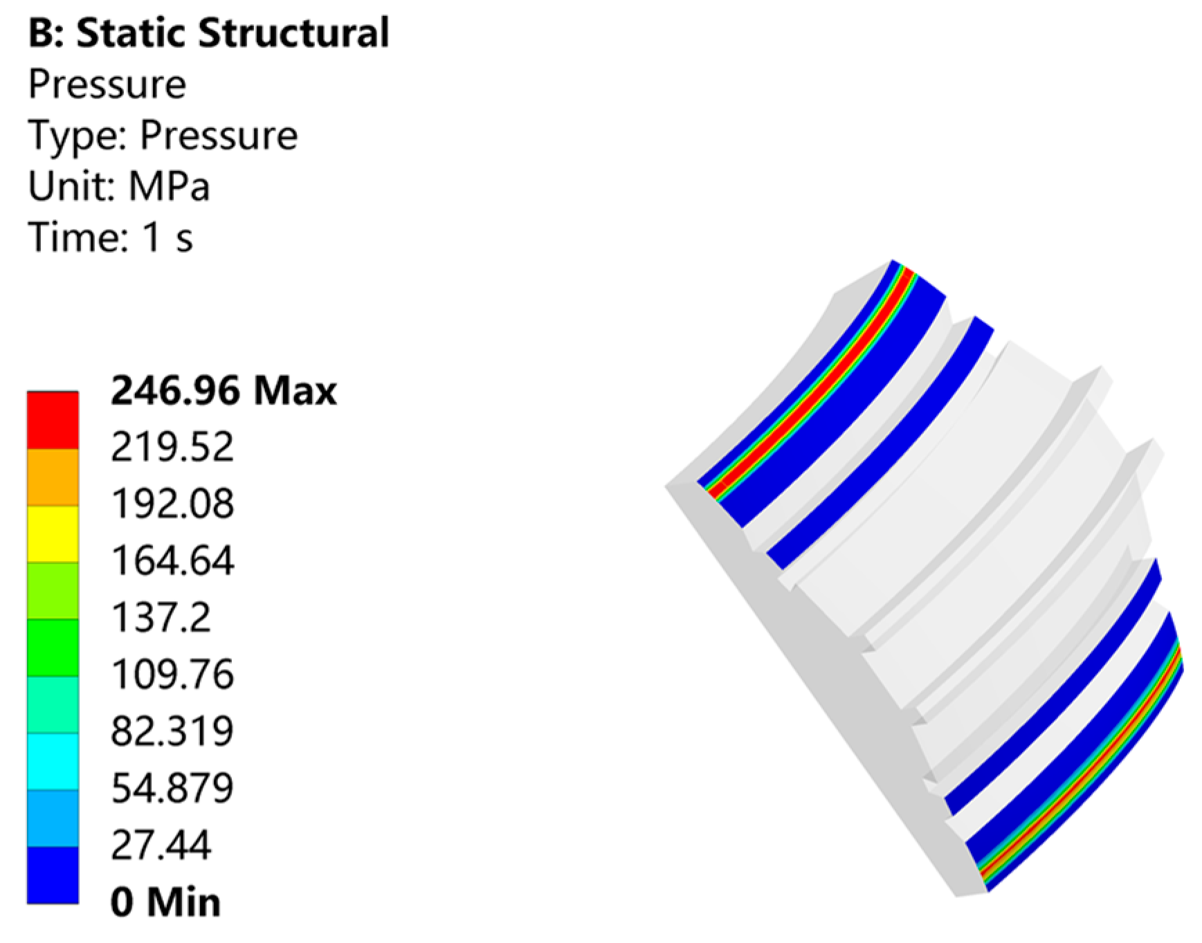
3.1.1. Seal Failure Criteria

In the operating condition, the subsea clamp connector needs the flange to provide sufficient preload, so that the residual contact force can ensure sufficient sealing, and thus avoid the occurrence of leakage. A schematic of the preload force transfer is shown in Figure 5.
Engineering has found a linear relationship between the sealing pressure and the contact stress, and defined the ratio of the mean contact stress applied to the unit effective area to the internal pressure, called the gasket coefficient, denoted by m [27], as follows:
p ¯ = m p n
where: p ¯ is the sealing specific pressure and p n is the internal medium pressure.
Therefore, to ensure reliable sealing of subsea connectors, it is necessary to satisfy:
p M a x p ¯
where: p m a x is the maximum contact pressure on the seal ring.

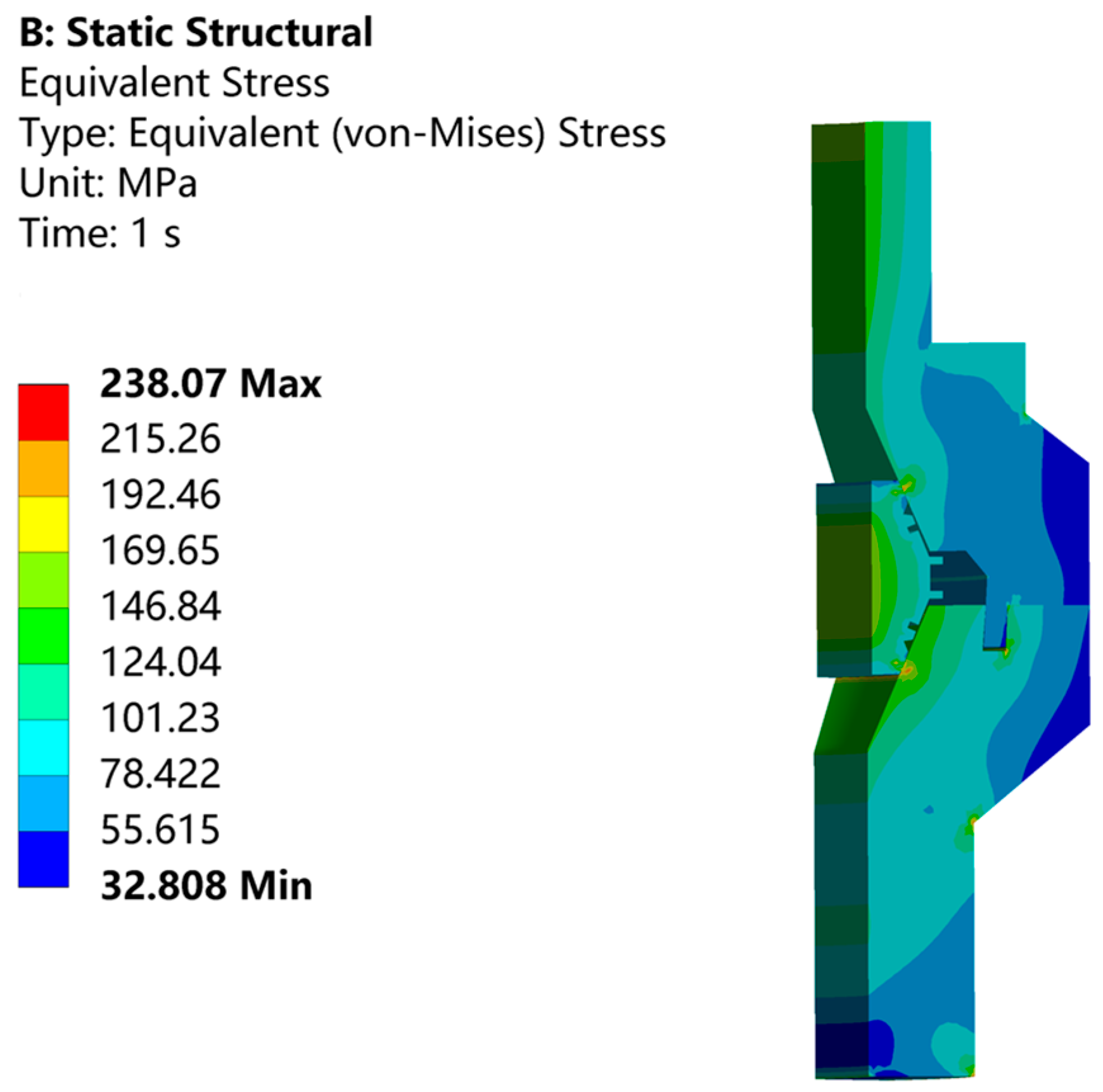
3.1.2. Yield Failure Criteria

Yield failure refers to the phenomenon that occurs when a material reaches its yield limit. When the subsea clamp connector is subjected to preload, the seal ring and other related parts will generate a certain amount of stress to resist small plastic deformation, when the external force is too large, the parts will undergo permanent plastic deformation, resulting in structural failure. The yield failure criterion adopts the fourth strength theory. Therefore, to ensure that no structural failure occurs in each part of the subsea connector, it is necessary to satisfy:
σ ε = 1 2 ( σ 1 σ 2 ) 2 + ( σ 2 σ 1 ) 2 + ( σ 3 σ 1 ) 2 < [ σ ]
where: σ ε is the calculated equivalent stress.

3.2. Kernel Density Estimation Method

The probability density distribution function of equivalent stress and maximum contact pressure needs to be obtained before reliability analysis of the subsea clamp connector. The sample set of equivalent stress and maximum contact pressure obtained from the Monte Carlo method of sampling can only be expressed as a histogram. Therefore, the histogram of the equivalent stress and maximum contact pressure is converted into the probability density distribution function of the sample set using the kernel density estimation method.
Using the idea of differentiation, the group distance of the frequency histogram is further reduced. As the group distance decreases, the width of the rectangle becomes smaller, so that in the limit the frequency histogram becomes a curve, and this curve is the probability density curve [28]. The formula is as follows:
f x = 1 2 n h i = 1 n 1 x h x i x + h
where: f ( x ) is probability density distribution function; h is bandwidth; and n is the number of samples.
According to this formula, in the actual calculation, the value of h must be given. The value of h cannot be too large or too small, too large does not satisfy the condition of h→→0, too small uses too few sample data points, and the error will be large. Therefore, there is more research on the choice of the value of h. Bandwidth h is usually selected by the AMISE rule.

3.3. Stress-Strength Interference Theory

For the subsea clamp connector related parts, when the material strength is greater than the stress, it is in a safe state. When the material strength is less than the stress, it fails. As shown in Figure 6, a schematic diagram of stress-strength interference theory, f s ( s 0 ) , is the probability density function of stress, and f S ( S ) is the probability density function of strength. The shadow where two normal distribution curves intersect is the subsea connector failure area.
Assuming that both strength and stress conform to the law of normal distribution, when the mean value of stress is less than the mean value of strength, the distribution area of the two will produce an overlapping interference region. When the stress is greater than the strength that occurs in this region, the structure is a failure. Therefore, the model for calculating the probability of failure in the interference region is the stress-strength interference model [29]. The probability of failure is as follows:
R = d R = f s s f S d S d s
where: R is probability of failure.
When the failure probability of the subsea clamp connector is calculated, its reliability can be obtained.

4. Case Study of Subsea Clamp Connector Based on MRSM

4.1. Finite Element Model of Subsea Clamp Connector

In the paper, the subsea clamp connector used in the Bohai Sea in China is selected as the object of study, and its reliability analysis is based on two response surfaces: equivalent stress and maximum contact pressure.
The structural parameters of metal seals and flanges affect the locking and sealing performance of subsea clamp connectors, which mainly contain seal ring thickness (x1), seal ring contact angle (x2), seal ring radius (x3), upper flange thickness (x4), upper and lower flange contact angle (x5), and lower flange thickness (x6) (as shown in Figure 7).
Its structure is shown in Figure 2, which mainly includes the locking block, flanges, seal ring, clamp flap, and other parts. Due to the large number of parts and complex contact relationships, the three core components of the upper and lower flanges and seal are selected for analysis in this numerical simulation. The one-eighth model is chosen for its axisymmetric structure for modeling, which can effectively improve the computational efficiency while ensuring the computational accuracy. In the numerical calculation model as shown Figure 8, the mesh all use hexahedral mesh, and the seal ring and the upper and lower flanges contact location of the grid size is set to 1 mm. The upper and lower flanges and other parts of the grid size is set to 3 mm, the number of grid is about 170,000. The constraints of the numerical model are set as follows: fixed constraints are applied to the lower flange position to limit all degrees of freedom; the upper and lower flange sides and seal ring sides are set as axisymmetric constraints and normal constraints to simulate the effect of the 1/8 model as an overall force analysis. The model load is set to apply a concentrated force on the upper flange end face to simulate an axial preload of 200 kN and a bending moment of 30 kN·m. A 35 MPa pressure load is applied to the internal surface to simulate the fluid pressure of the medium inside the connector. The initial sample data are shown in Table 1.
The material parameters for each component of the model are set as shown in Table 2.

4.2. Reliability Analysis of Subsea Clamp Connector

The finite element analysis allows the equivalent stress cloud of the subsea clamp connector (shown in Figure 9) and the maximum contact pressure cloud of the seal (shown in Figure 10) to be obtained. As can be seen from the graph, the maximum equivalent stress on the upper and lower flanges is 238.07 MPa and the yield strength of the seal is 330 MPa, both of which are less than the yield strength of the material. The maximum contact pressure on the seal is 246.96 MPa, which is greater than the minimum sealing specific pressure of 227.5 MPa (according to the ASME standard, the gasket factor m is selected as 6.5). Therefore, it is clear from the two failure criteria that the sealing structure of the subsea clamp connector meets the design requirements. The performance of the subsea clamp connector is good under the rated conditions. The analysis of the reliability under the relevant parameters can be continued.
By varying the main structural parameters of the subsea clamp connector, a sensitivity diagram expressing the effect of different parameters can be obtained, as shown in Figure 11, identifying the seal radius (x3), the upper flange contact angle (x5), and the internal pressure of the medium (x7) as the main influencing factors in the subsequent analysis.
In the paper, the Latin hypercube sampling method was chosen to obtain the test data. The Latin hypercube sampling technique was a stratified sampling method, which means that the characteristics of the overall sample can be reflected by a smaller sample size, which can greatly reduce the number of test points and save calculation time. The test data obtained from the sampling were then analyzed using finite element software, and the response surface functions for the equivalent stress S and the maximum contact pressure L were fitted separately based on the least squares method.
S = 66190.32642 375.23899 x 3 + 929.50191 x 5 + 761.76991 x 7 0.914321 x 3 x 5 5.04020 x 3 x 7 2.65118 x 5 x 7 + 4.69174 x 3 2 2.68596 x 5 2 0.076828 x 7 2
L = 105347.587 108.7357 x 3 1066.17 x 5 1417.9 x 7 11.165 x 3 x 5 0.341 x 3 x 7 + 8.4 x 5 x 7 + 12.21 x 3 2 + 5.438 x 5 2 + 3.29541 x 7 2
The response surface function obtained from the above fit was subjected to the Monte Carlo sampling method to obtain the sampling iterations shown in Figure 12 and Figure 13. The figure shows that after 2000 cycles, subsea clamp connector equivalent stress and maximum contact pressure sampling curves gradually plateau, which means that the data sampling requirements can be met using 2000 sampling cycles.
The mean value of the response surface S is 276.56 MPa with a variance of 226. The mean value of the response surface L is 330.03 MPa with a variance of 205. The red line in the figure is the normal distribution curve obtained by fitting, as shown in Figure 14 and Figure 15.
First, the probability density expression of the actual response surface is obtained. Then, the intensity probability density expression is obtained. Finally, the reliability of subsea clamp connector under each single response can be obtained by using the stress-strength interference theory:
P t ( S ) = f s ( s ) s f S ( S ) d s d S = 0.0048
P t ( L ) = f l ( l ) L f L ( L ) d l d L = 0.008
P t ( S ) and P t ( L ) are the failure probabilities obtained from the yield failure criterion and the seal failure criteria. The combined probability of failure is:
P ( S L ) = P ( S ) + P ( L ) P ( S ) P ( L ) = 0.0127
Therefore, the reliability of the subsea clamp connector is:
1 P ( S L ) = 98.73 %
The reliability is the reliability performance of the subsea clamp connector in the initial state of production. According to a literature study [30], this reliability belongs to the low-level fault and meets its working requirements.

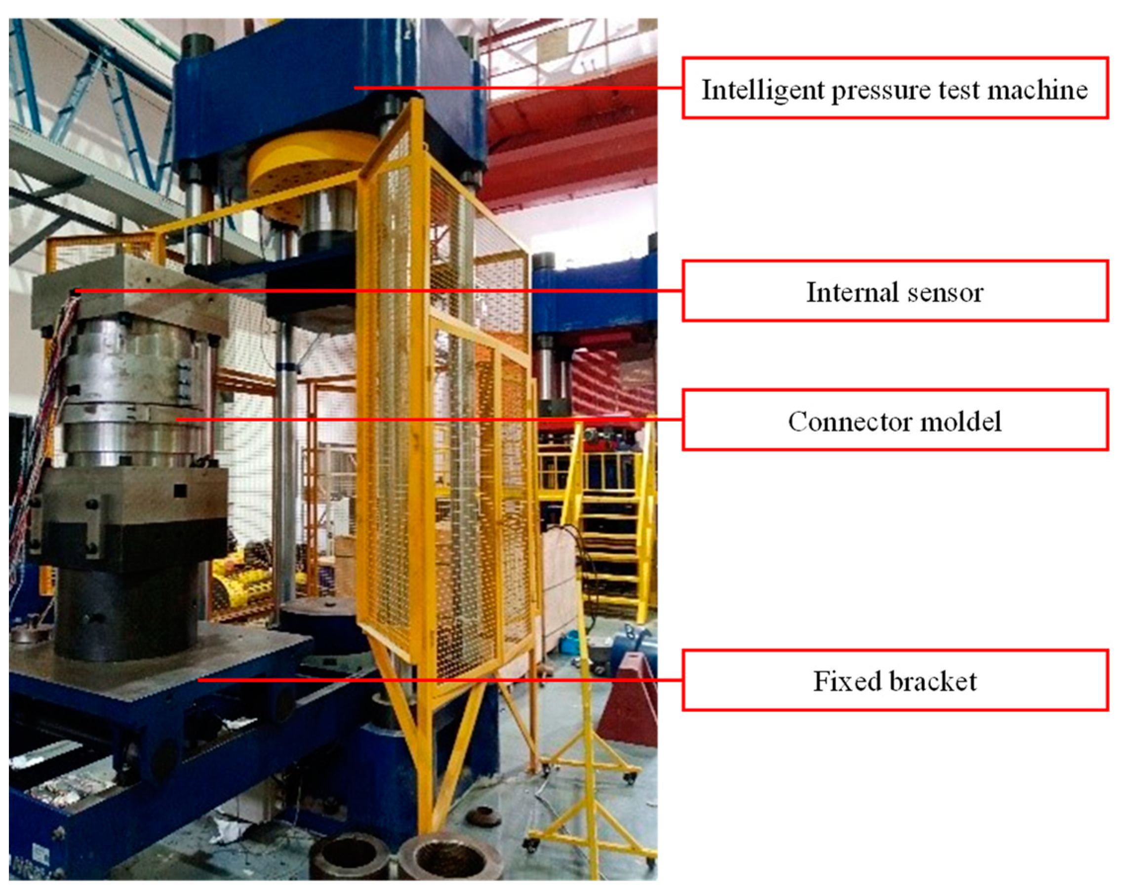
5. Model Test Verification

The test system shown in Figure 16 is used to check the sealing reliability of the subsea clamp connector studied in this paper. The test system is mainly composed of connector model, intelligent pressure test machine, internal sensor, and fixed brackets, etc. The test was carried out using a stepwise pressurization method, where the internal pressure of the connector model was gradually increased to 52.5 MPa. The pressure is loaded in 12 steps with a 5-min holding operation at each stage and 15 min at the last step. During the holding period measure, if the pressure drop is less than 5% of the test pressure, observe for leaks and abnormal sounds.
The pressure drop rate formed from the measured pressure drop data is shown in Figure 17. The maximum pressure drop rate during the whole pressurization process is 2%, which is lower than the standard requirement of 5%. As pressure increases, the pressure drop rate decreases and the internal pressure retention performance becomes stable. After the first pressurization step, the pressure is released and then re-pressurized in two steps to verify the accuracy of the above test procedure. The results of the model tests show that the subsea clamp connector has good sealing performance to meet the design requirements during both the pressurization and pressure-hold periods. It validates the applicability of the MRSM for the safe design of subsea clamp connectors.

6. Conclusions

The paper proposes a reliability prediction method based on the multiple response surface method for subsea clamping connectors and provides a specific analysis process for the structural characteristics and load bearing of subsea clamping connectors. The reliability analysis and model test validation are carried out with a model of subsea clamp connector, and the main conclusions are formed as follows:
(1)
The multiple response surface method can accurately predict the reliability of underwater clamp connectors under different structural characteristic parameters and load conditions due to its advantages of simultaneously considering multiple failure factors of the system.
(2)
The reliability of the subsea clamp connector analyzed in this paper is mainly affected by the radius of the sealing ring, the contact angle of the upper and lower flanges, and the internal pressure of the medium, and the reliability is 98.73% by calculation.
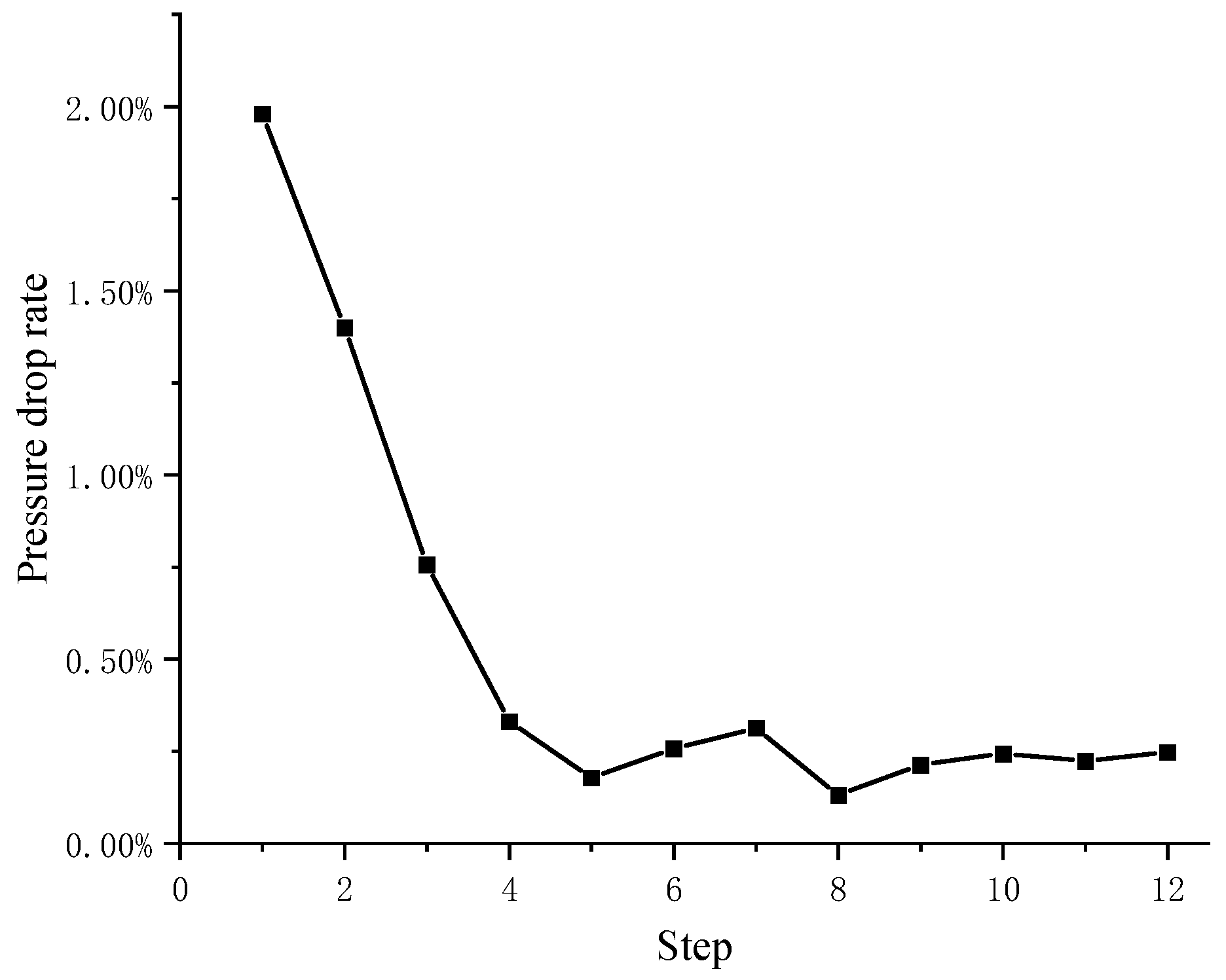
(3)
The maximum pressure drop rate of the internal pressure test of the underwater clamp connector analyzed in this paper is 2%, the pressure drop rate decreases with increasing pressure, and the internal pressure retaining performance tends to be stable. The applicability of the MRSM in the safety design of subsea clamp connectors is verified.

Author Contributions

Conceptualization, M.D.; methodology, W.A.; validation, B.C.; formal analysis, B.C.; investigation, X.Z.; resources, W.A.; data curation, Y.W.; writing—original draft preparation, W.A.; writing—review and editing, Y.W.; All authors have read and agreed to the published version of the manuscript.

Funding

This research was funded by National Natural Science Foundation, grant number 52222111.

Institutional Review Board Statement

Not applicable.

Informed Consent Statement

Not applicable.

Data Availability Statement

Not applicable.

Conflicts of Interest

The authors declare no conflict of interest.

References

  1. Chen, S. Current Situation and Improvement Method of Offshore Oil Drilling Platform Equipment Management. Chem. Manag. 2021, 8, 191–192. [Google Scholar]
  2. Li, Q.; Zhu, H.; Li, X. The Current State and Future of Deep Water Subsea Production Technology. Chin. Eng. Sci. 2016, 18, 76–84. [Google Scholar]
  3. Wang, L. The development status and trend of Chinese offshore petroleum engineering industry. China Pet. Chem. Stand. Rain Qual. 2022, 42, 142–144. [Google Scholar]
  4. Wang, Y. Subsea Production Systems and Engineering; Publishing House of China University of Petroleum: Dongying, China, 2017. [Google Scholar]
  5. Peng, F.; Duan, M.; Wang, J. Optimisation method for mathematical model of deepwater collet connector locking mechanism. Ships Offshore Struct. 2015, 11, 575–590. [Google Scholar] [CrossRef]
  6. Zhao, H.; Chen, R.; Luo, X.; Duan, M.; Lu, Y.; Fu, G.; Tian, H.; Ye, D. Metal sealing performance of subsea X-tree wellhead connector sealer. Chin. J. Mech. Eng. 2015, 28, 649–656. [Google Scholar] [CrossRef]
  7. Hu, X.; Yun, F.; Shi, L. Structural Optimization of Metal Sealing Ring of Underwater Clamp Connector. Lubr. Seal. 2022, 47, 117–124. [Google Scholar]
  8. Wang, R. Sealing Structure Optimization Analysis and Performance Research of Deep Sea Horizontal Clamp Connector; Harbin Engineering University: Harbin, China, 2017. [Google Scholar]
  9. Yun, F.; Wang, G.; Yan, Z.; Jia, P.; Xu, X.; Wang, L.; Sun, H.; Liu, W. Analysis of Sealing and Leakage Performance of the Subsea Collet Connector with Lens-Type Sealing Structure. J. Mar. Sci. Eng. 2020, 8, 444. [Google Scholar] [CrossRef]
  10. Li, Y.; Zhao, H.; Wang, D.; Xu, Y. Metal sealing mechanism and experimental study of the subsea wellhead connector. J. Braz. Soc. Mech. Sci. Eng. 2020, 42, 26. [Google Scholar] [CrossRef]
  11. Liu, D.; Yun, F.; Jiao, K.; Wang, L.; Yan, Z.; Jia, P.; Wang, X.; Liu, W.; Hao, X.; Xu, X. Structural Analysis and Experimental Study on the Spherical Seal of a Subsea Connector Based on a Non-Standard O-Ring Seal. J. Mar. Sci. Eng. 2022, 10, 404. [Google Scholar] [CrossRef]
  12. Wan, B.; Sun, Z.; Jiang, Y.; Cai, Y.; Chen, J. Reliability analysis of underwater connectors based on fault tree. China Shipp. Surv. 2015, 12, 85–87. [Google Scholar]
  13. Zhang, K.; Duan, M.; Luo, X.; Hou, G. A fuzzy risk matrix method and its application to the installation operation of subsea collet connector. J. Loss Prev. Process Ind. 2017, 45, 147–159. [Google Scholar] [CrossRef]
  14. Chen, Z.; Liu, G.; Wang, Y. Fault diagnosis of subsea collet connector based on dynamic Bayesian network. Chin. J. Saf. 2020, 30, 81–87. [Google Scholar]
  15. Hørte, T.; Reinås, L.; Wormsen, A.; Aardal, A. Structural Reliability Analysis Method for Assessing the Fatigue Capacity of Subsea Wellhead Connectors. In Proceedings of the ASME 2020 39th International Conference on Ocean, Offshore and Arctic Engineering, Online, 3–7 August 2020. [Google Scholar] [CrossRef]
  16. Bhardwaj, U.; Teixeira, A.P.; Soares, C.G. Reliability assessment of a subsea pipein-pipe system for major failure modes. Int. J. Pres. Ves. Pip. 2020, 188, 104177. [Google Scholar] [CrossRef]
  17. Pang, N.; Jia, P.; Liu, P.; Yin, F.; Zhou, L.; Wang, L.; Yun, F.; Wang, X. A Fuzzy Markov Model for Risk and Reliability Prediction of Engineering Systems: A Case Study of a Subsea Wellhead Connector. Appl. Sci. 2020, 10, 6902. [Google Scholar] [CrossRef]
  18. Wang, Y.; Liu, S.; Chen, Z. Dynamic Bayesian networks for reliability evaluation of subsea wellhead connector during service life based on Monte Carlo method. J. Loss Prev. Process Ind. 2021, 71, 104487. [Google Scholar] [CrossRef]
  19. Tsai, L.W.; Alipour, A. Structural health monitoring and fatigue life reliability assessment of a flexible structure in extreme wind. J. Civ. Struct. Health Monit. 2023, 13, 677–691. [Google Scholar] [CrossRef]
  20. Simon, O.; Fei, T.; Mohsen, S.; Chen, C. Risk Based Verification for Subsea Pipeline Repair Connectors and a Case Study. In Proceedings of the Offshore Technology Conference, Houston, TX, USA, 1–4 May 2023; p. 32412. [Google Scholar] [CrossRef]
  21. Das, P.K.; Zheng, Y. Cumulative formation of response surface and its use in reliability analysis. Probabilistic Eng. Mech. 2000, 15, 309–315. [Google Scholar] [CrossRef]
  22. Goswami, S.; Ghosh, S.; Chakraborty, S. Reliability analysis of structures by iterative improved response surface method. Struct. Saf. 2016, 60, 56–66. [Google Scholar] [CrossRef]
  23. Zhang, C.; Liu, L.; Sun, X. Reliability Analysis for Aero-engine Blades with Multiple Response Surface Method. J. Harbin Eng. Univ. 2016, 21, 22–27. [Google Scholar]
  24. Cheng, L. Research on Structural Reliability Analysis Method Based on Multiple Response Surfaces of Coupling Failure; Harbin Engineering University: Harbin, China, 2016. [Google Scholar]
  25. Liu, Z.; Lin, H.; Li, L. Analysis on the Reliability of Tunnel System Based on Multiple Response Surface Methodology and Monte Carlo Method. Mod. Tunn. Technol. 2022, 59, 78–87. [Google Scholar]
  26. Zhai, X. Structural Reliability Analysis and Optimization of Offshore Fan Connectors Based on Multiple Response Surface Method; China University of Petroleum: Beijing, China, 2022. [Google Scholar]
  27. Li, H. Factor Analysis of the Gasket Seal Failure. Liaoning Chem. Ind. 2013, 42, 1007–1009. [Google Scholar]
  28. Węglarczyk, S. Kernel density estimation and its application. XLVIII Semin. Appl. Math. 2018, 23, 8. [Google Scholar] [CrossRef] [Green Version]
  29. Niu, L.; Dong, H.; Zhao, X.; Li, X.; Yan, N. Reliability of Separation Nuts Based on Stress-Intensity Interference Model. Equip. Environ. Eng. 2022, 19, 8–13. [Google Scholar]
  30. Pang, N.; Jia, P.; Wang, L. Reliability analysis of subsea connector structure. J. Harbin Eng. Univ. 2021, 42, 68–73. [Google Scholar]
Figure 1. Subsea clamp connectors (https://www.fogt.com/subsea-connector (accessed on 3 May 2023)).
Jmse 11 01378 g001
Figure 2. Schematic of the overall structure of the subsea clamp connector. 1—Locking bolt hole; 2—Three-flap clamp piece; 3—Axial support plate; 4—Clamp jaws; 5—Upper flange; 6—Seal ring; 7—Bottom flange.
Jmse 11 01378 g002
Figure 3. Dual sealing structure with lens seal and O-type seal.
Jmse 11 01378 g003
Figure 4. Multiple response surface method calculation process.
Jmse 11 01378 g004
Figure 5. Schematic of preload force transmission.
Jmse 11 01378 g005
Figure 6. Schematic of stress-strength interference theory.
Jmse 11 01378 g006
Figure 7. Subsea clamp connector structure parameterization.
Jmse 11 01378 g007
Figure 8. Constraints and loads of the numerical model.
Jmse 11 01378 g008
Figure 9. Equivalent stress cloud diagram.
Jmse 11 01378 g009
Figure 10. Maximum contact pressure cloud diagram.
Jmse 11 01378 g010
Figure 11. Sensitivity of input parameters to the response surface.
Jmse 11 01378 g011
Figure 12. Iteration diagram of the response surface S.
Jmse 11 01378 g012
Figure 13. Iteration diagram of the response surface L.
Jmse 11 01378 g013
Figure 14. Normal distribution plot fitted to response plane S.
Jmse 11 01378 g014
Figure 15. Normal distribution plot fitted to response plane L.
Jmse 11 01378 g015
Figure 16. Reliability performance verification test model.
Jmse 11 01378 g016
Figure 17. Diagram of pressure drop rate for each stage during the test.
Jmse 11 01378 g017
Table 1. Initial sample data.
Random Variable ParametersSymbolsDistribution TypeAverage Value (mm)Coefficient of VariationStandard Deviation
Seal thicknessx1Normal distribution110.020.22
Sealing ring contact anglex2Normal distribution1070.022.14
Seal radiusx3Normal distribution740.021.48
Upper flange thicknessx4Normal distribution260.020.52
Upper flange contact anglex5Normal distribution1450.022.9
Lower flange thicknessx6Normal distribution380.020.76
Internal pressurex7Normal distribution350.020.7
Table 2. Material parameters.
Part NameMaterialsStrength Limit
(MPa)
Yield Limit (MPa)Elastic Modulus (GPa)Poisson RatioDensity (g/cm3)
Upper and lower flange12Cr2Mo15403402110.297.85
Seals3165153102110.38.0
Disclaimer/Publisher’s Note: The statements, opinions and data contained in all publications are solely those of the individual author(s) and contributor(s) and not of MDPI and/or the editor(s). MDPI and/or the editor(s) disclaim responsibility for any injury to people or property resulting from any ideas, methods, instructions or products referred to in the content.

