
Application of Multi-Cylinder Synchronous Control for Telescopic Mechanism of Marine Steel Pile Cleaning Equipment

 , and
, and 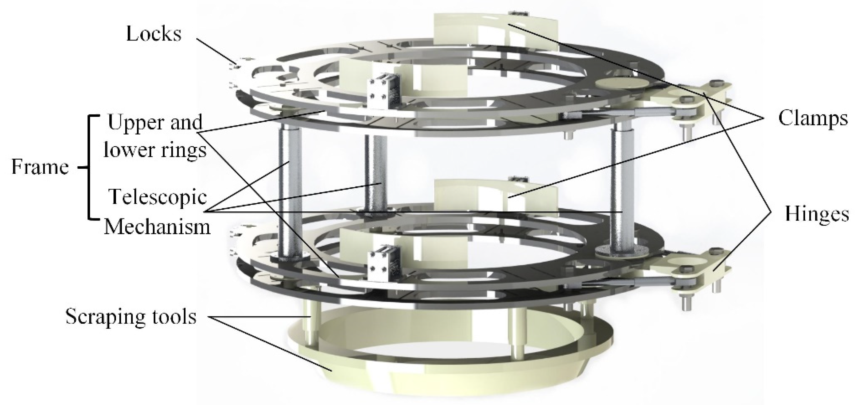
Abstract
:1. Introduction
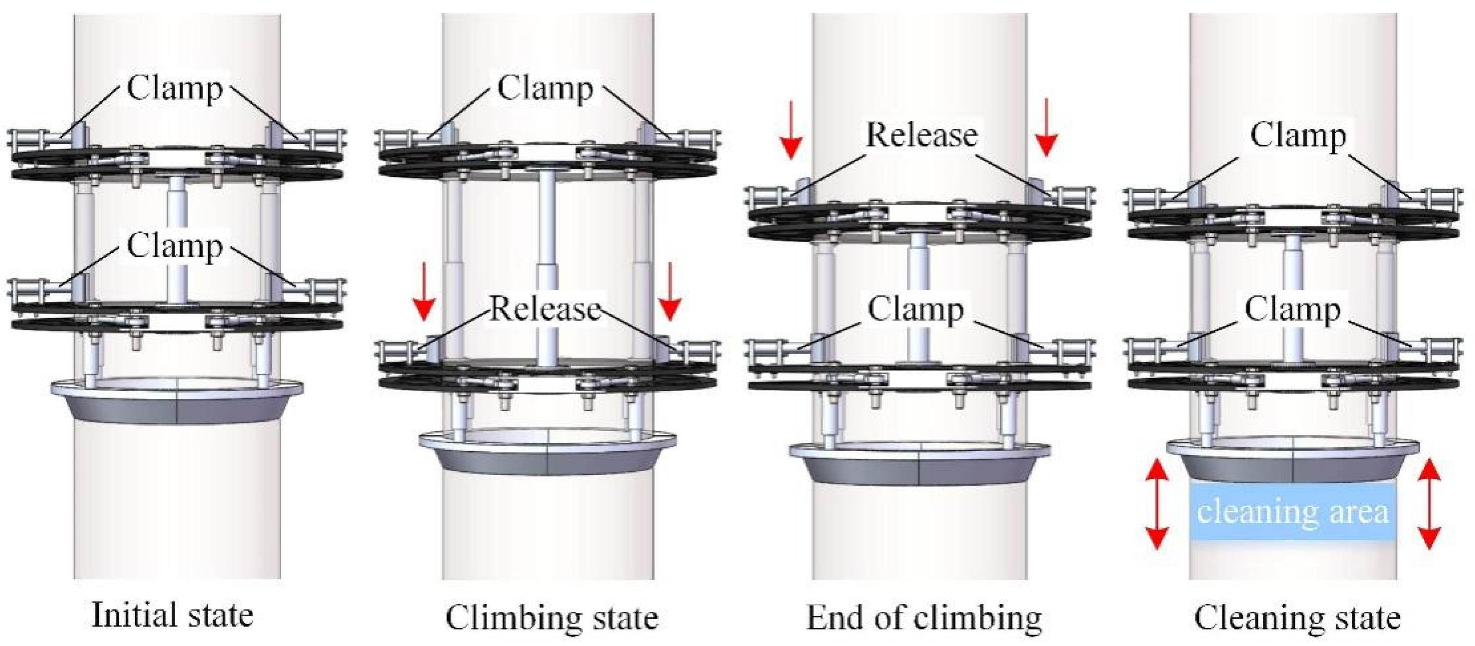
2. Cleaning Equipment Structure Scheme and Working Principle
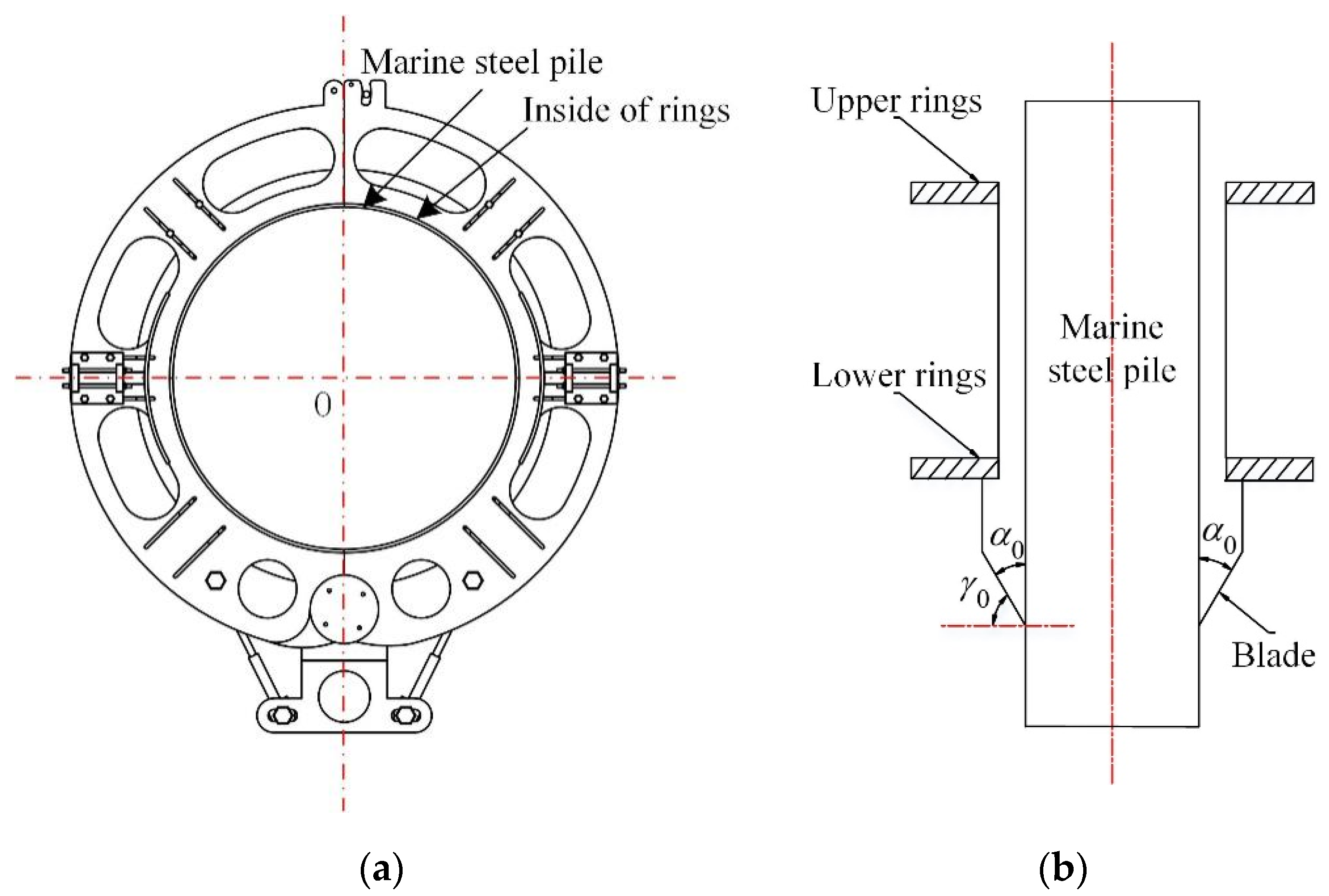
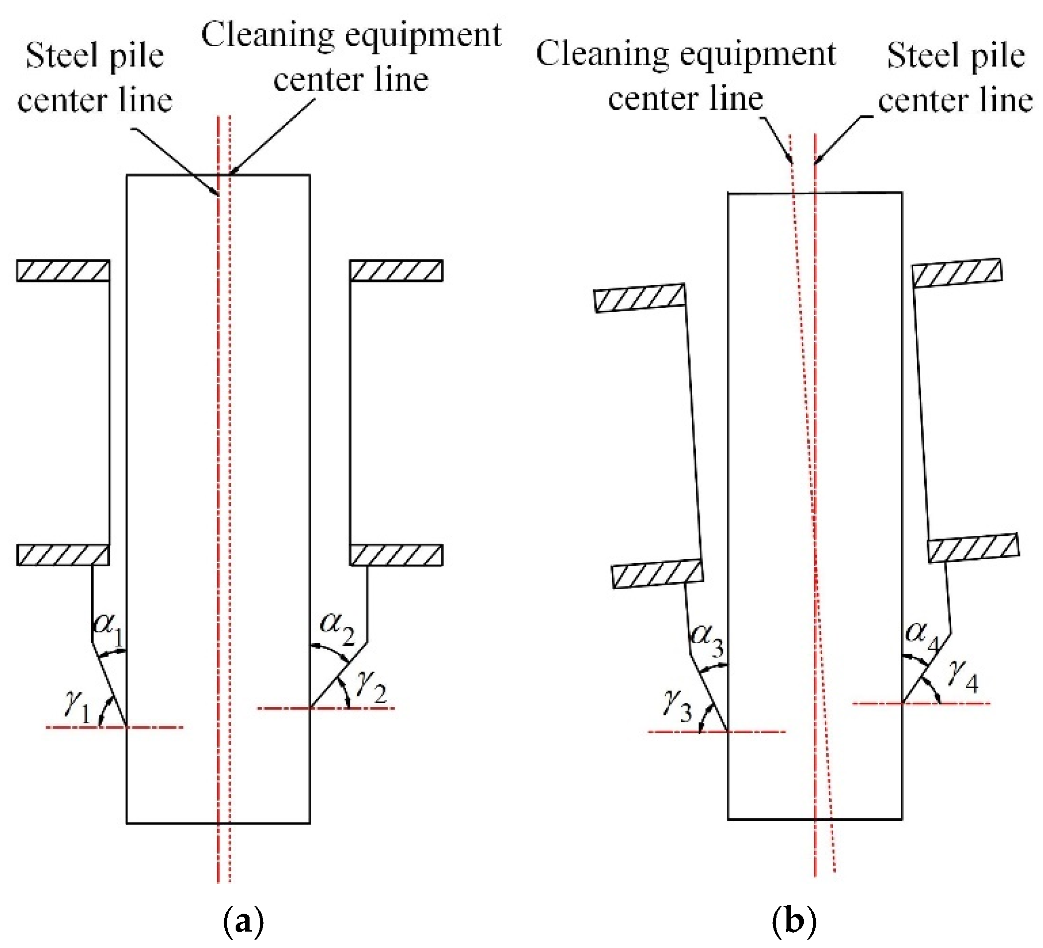
3. Influence of Telescopic Mechanism Synchronization on Scraping Tools
4. Synchronous Modeling and Simulation of the Telescopic Mechanism
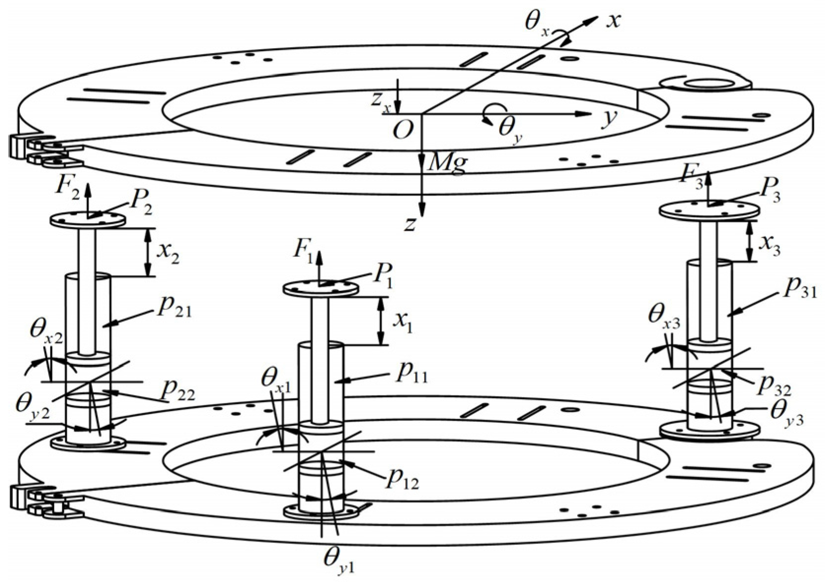
4.1. Modeling of Synchronous Control System of the Telescopic Mechanism
- (1)
- Assuming that the piston of the hydraulic cylinder does not rotate in the cavity, there is no degree of freedom to twist around the z-axis for the telescopic load;
- (2)
- Assuming that the synchronization error of the three-cylinder is much smaller than the distance between the installation positions of each hydraulic cylinder, the telescopic load mainly moves in the vertical direction, that is, the z-axis direction, and can be ignored along the x-axis and y-axis directions;
- (3)
- Assuming that the hydraulic cylinder piston is not affected by the lateral force, regardless of the gravity of the piston and cylinder, the output force Fi (I = 1, 2, 3) of the piston rod of the hydraulic cylinder is along the direction of the piston rod, and the angle with the z-axis is approximately zero;
- (4)
- Assume that the upper flange of the hydraulic cylinder and the upper ring are connected by a point centered on the flange.
4.1.1. Equation of Motion of Telescopic Mechanism
4.1.2. Telescopic Load and Point Contact Position Equation of Hydraulic Cylinder
4.1.3. The Equation of Motion of the Piston Rod of a Hydraulic Cylinder
4.1.4. Load Pressure Dynamic Characteristic Equation of Asymmetric Hydraulic Cylinder
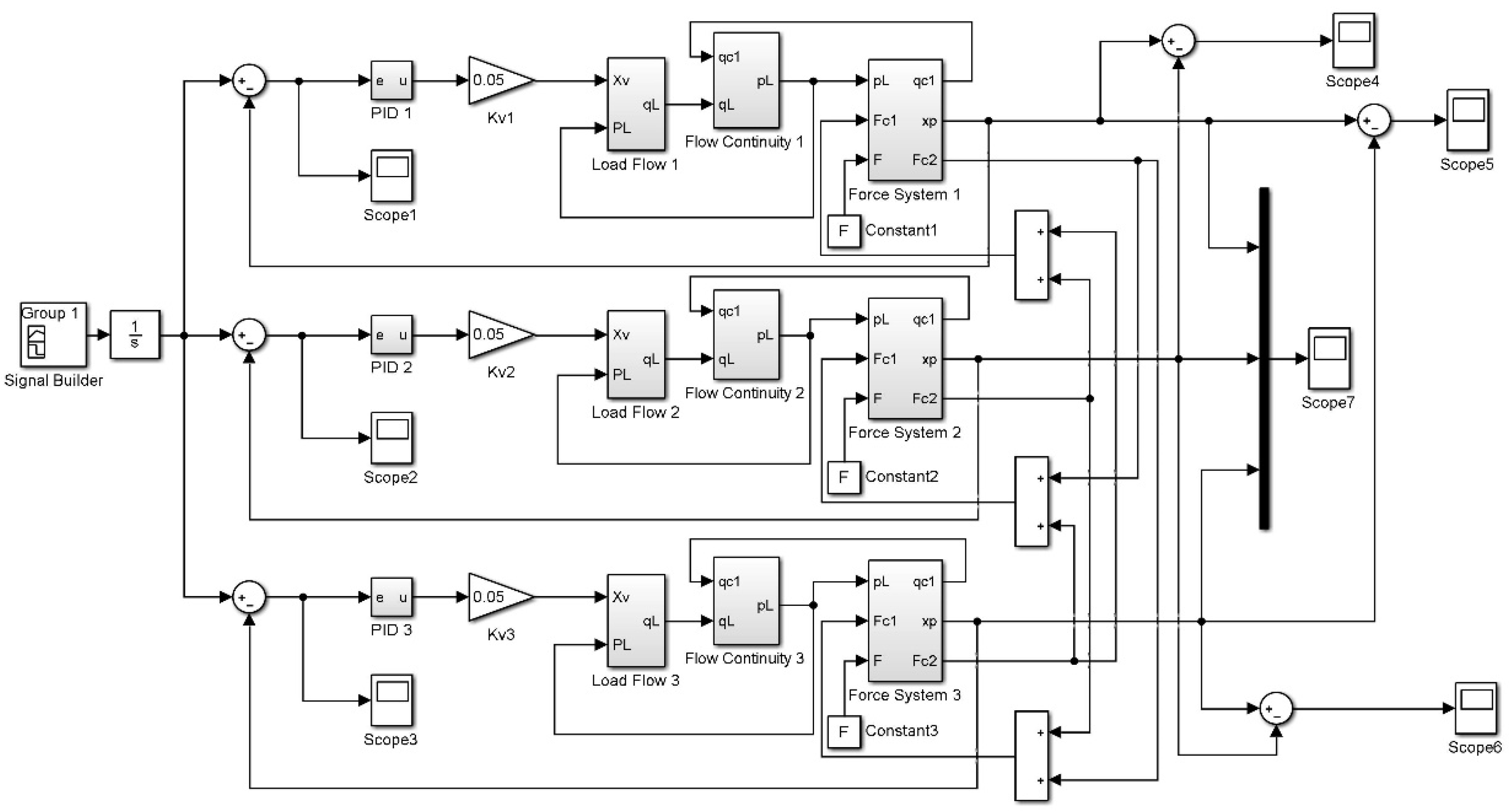
4.1.5. Mathematical Model of Three-Cylinder System
4.2. Synchronous Control Simulation of Telescopic Mechanism
5. Synchronous Test of the Telescopic Mechanism
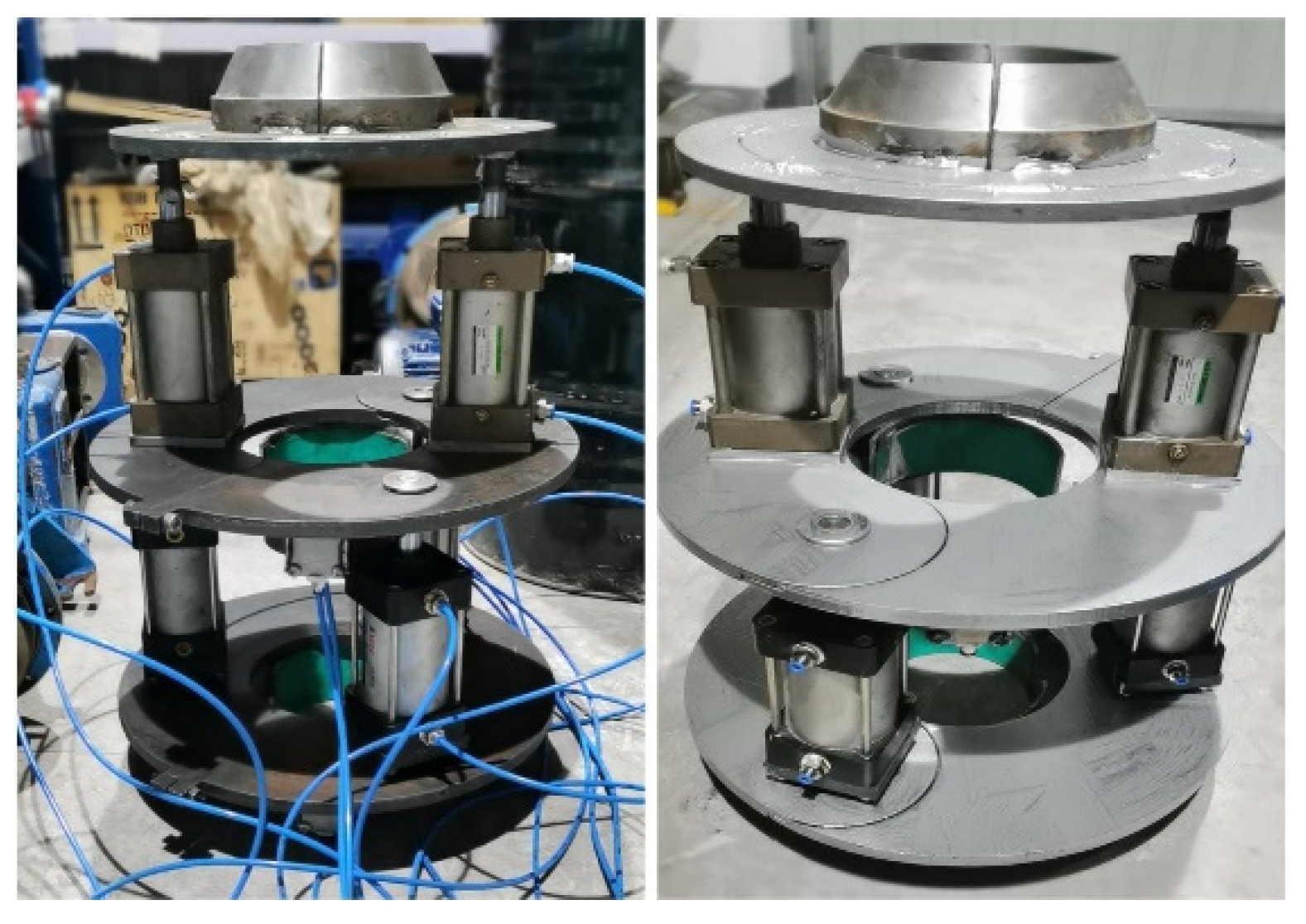
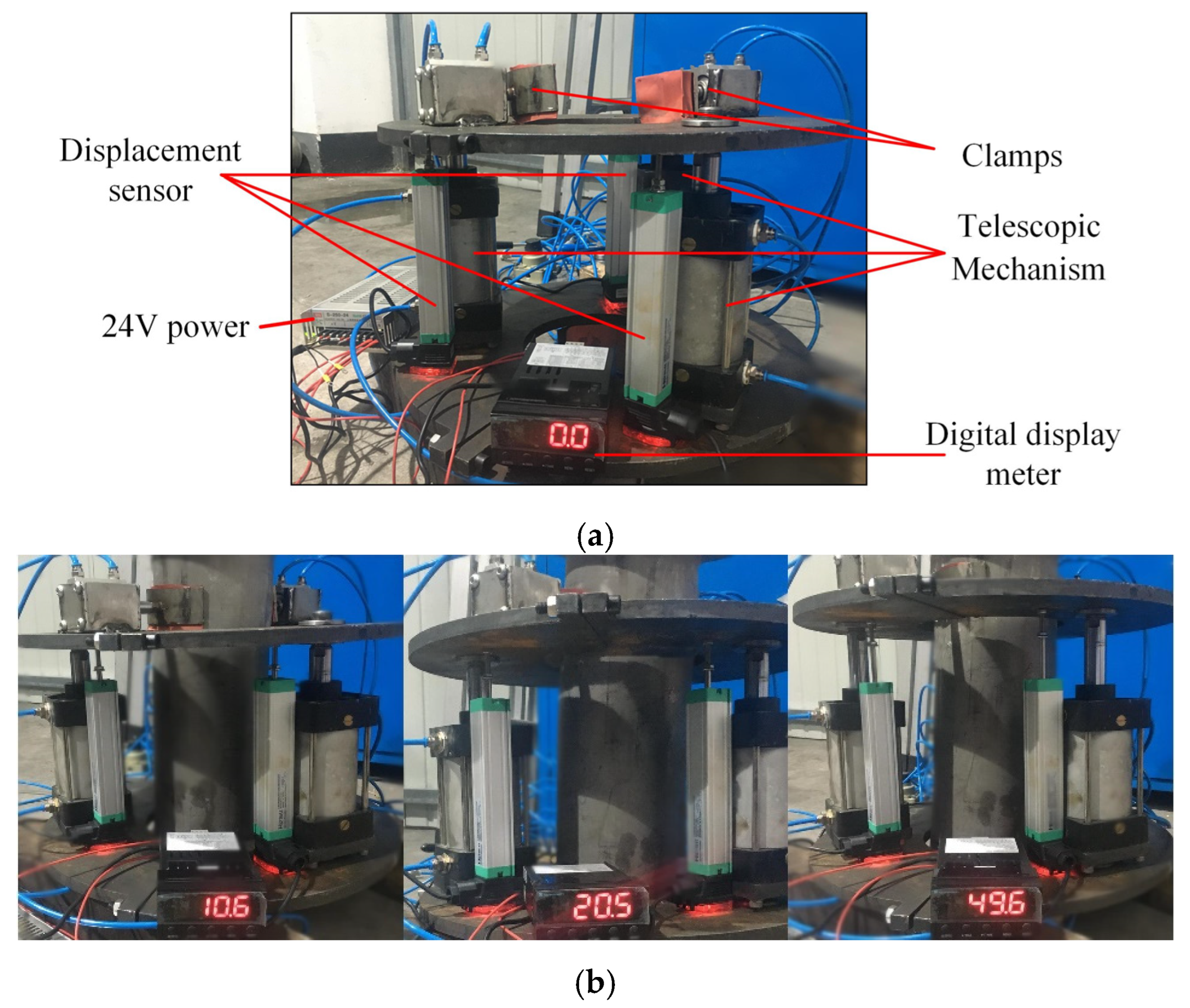
5.1. Development and Test of Cleaning Equipment
5.2. Test Results and Discussion
6. Conclusions
- (1)
- In order to clean up the fouling organisms attached to the offshore infrastructure, this paper designed a new configuration of marine steel pile cleaning equipment using the scraping method and its telescopic mechanism with a multi-cylinder synchronous control strategy and process and produced a test prototype.
- (2)
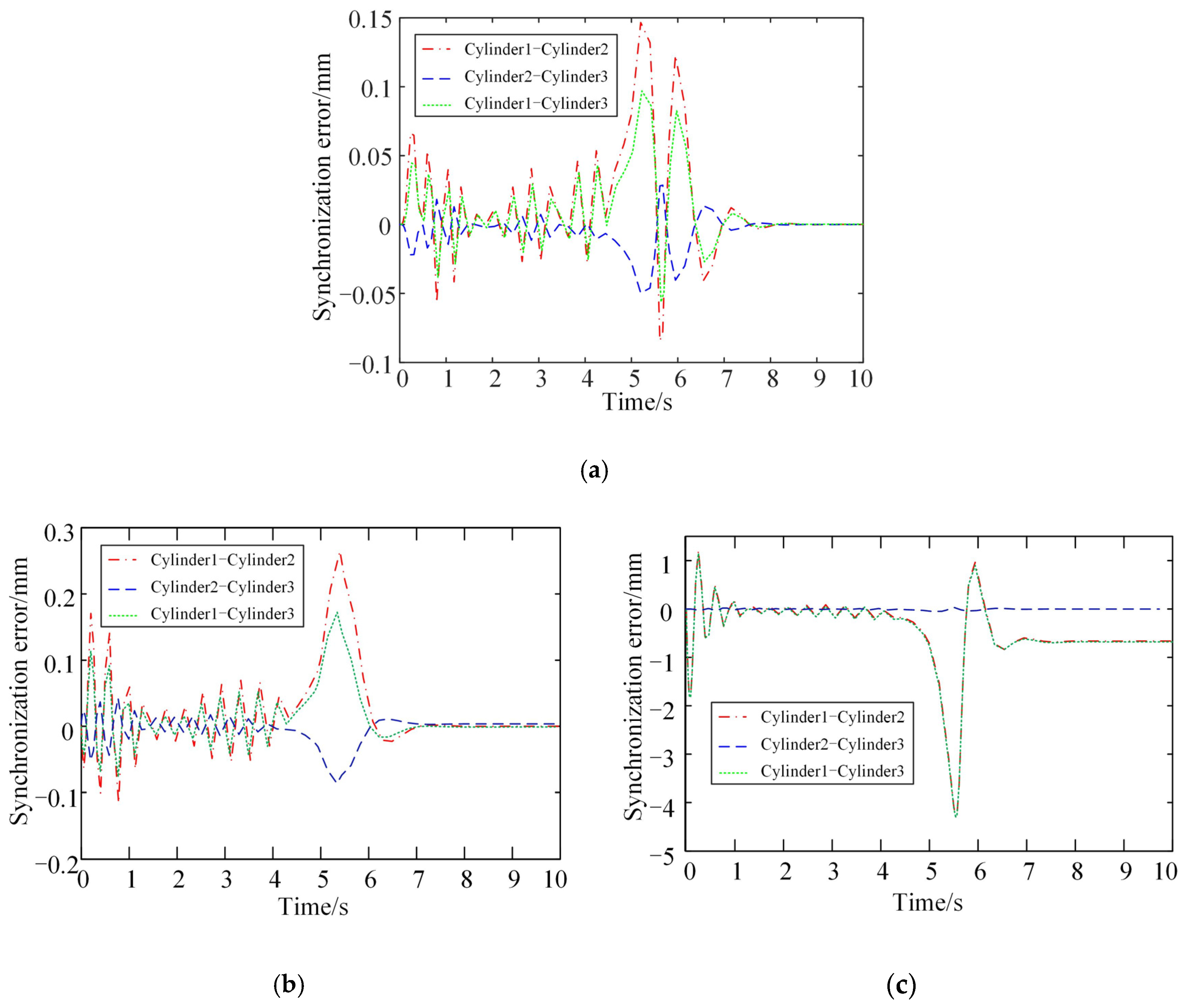
- The simulation model of the operation process of the marine steel pile cleaning equipment was established, and the simulation of its multi-cylinder synchronous control under multiple working conditions was completed. Through the simulation solution, the maximum displacement synchronization error between each cylinder of the telescopic mechanism under the no-load condition was 0.15 mm. When the three hydraulic cylinders were loaded by the scraping reaction force, the maximum synchronization error between each cylinder was about 0.28 mm; when a single hydraulic cylinder was loaded with the scraping reaction force, the maximum synchronization error between each cylinder was about 4 mm. In all three cases, the telescopic mechanism achieved good synchronization in the simulation process.
- (3)
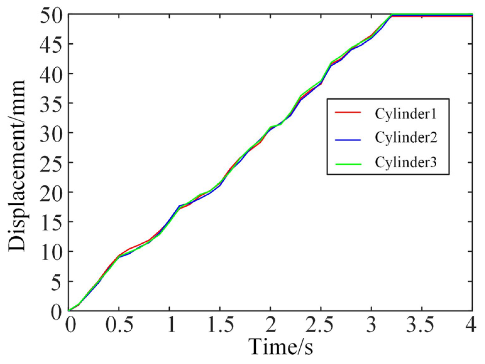
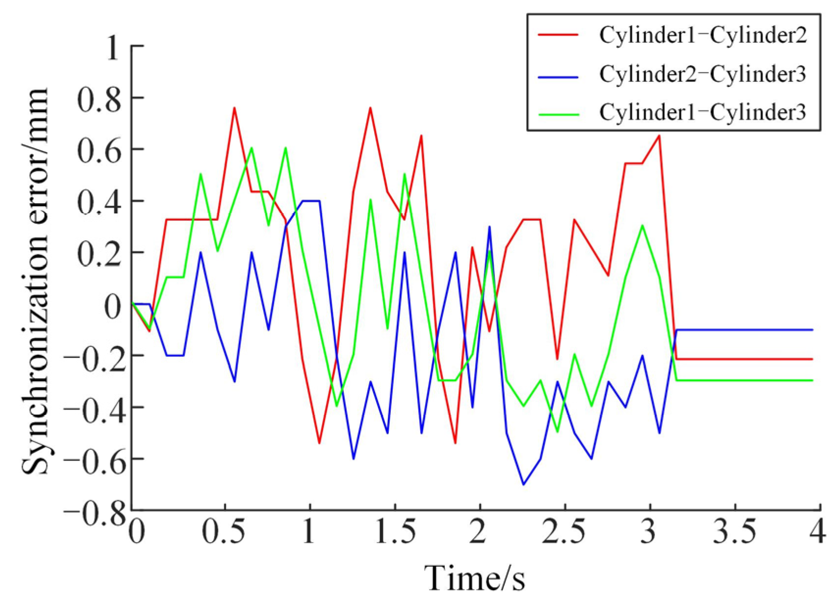
- Through the no-load test of the telescopic mechanism, the synchronization of the telescopic mechanism of the prototype of the cleaning equipment was preliminarily verified. The test results showed that the relative errors between the three cylinders and the target displacement were 0.8%, 0.4%, and 0.2%, respectively, to ensure that the equipment reached the designated working position at the given working speed. The displacement synchronization error of each cylinder was controlled within 1 mm, and the telescopic mechanism had good telescopic synchronization, which can prevent the eccentricity and tilt of the cleaning equipment during its operation while ensuring its stability.
Author Contributions
Funding
Institutional Review Board Statement
Informed Consent Statement
Data Availability Statement
Conflicts of Interest
References
- Hopkins, G.; Davidson, I.; Georgiades, E.; Floerl, O.; Morrisey, D.; Cahill, P. Managing biofouling on submerged static artificial structures in the marine environment–assessment of current and emerging approaches. Front. Mar. Sci. 2021, 8, 759194. [Google Scholar] [CrossRef]
- Azis, P.K.A.; Al-Tisan, I.; Al-Daili, M.; Green, T.N.; Ba-Mardouf, K.; Al-Qahtani, S.A.; Al-Sabai, K. Marine macrofouling: A review of control technology in the context of an on-line experiment in the turbine condenser water box of Al-Jubail Phase-I power MSF plants. Desalination 2003, 154, 277–290. [Google Scholar] [CrossRef]
- Magin, C.M.; Cooper, S.P.; Brennan, A.B. Non-toxic antifouling strategies. Mater. Today 2010, 13, 36–44. [Google Scholar] [CrossRef]
- Yebra, D.M.; Kiil, S.; Dam-Johansen, K. Antifouling technology—Past, present and future steps towards efficient and environmentally friendly antifouling coatings. Prog. Org. Coat. 2004, 50, 75–104. [Google Scholar] [CrossRef]
- Ren, W.; Chen, Y.; Xv, H.; Chen, Y.; Xie, Z.; Chen, Y. Study of Corrosion Mechanism and Corrosion Status of Offshore Wind Power Equipment. Ship Eng. 2021, 43, 1–5. [Google Scholar]
- Telegdi, J.; Trif, L.; Románszki, L. Smart anti-biofouling composite coatings for naval Applications. In Smart Composite Coatings and Membranes; Woodhead Publishing: Cambridge, UK; Elsevier: Amsterdam, The Netherlands, 2016; pp. 123–155. [Google Scholar]
- Zan, Y.; Guo, R.; Yuan, L.; Ma, Q.; Zhou, A.; Wu, Z. Experimental study of a suspended subsea module at different positions in the splash zone. Mar. Struct. 2021, 77, 102935. [Google Scholar] [CrossRef]
- Heaf, N.J. The Effect of Marine Growth On The Performance of Fixed Offshore Platforms in the North Sea. In Proceedings of the 11th Annual Offshore Technology Conference, Houston, TX, USA, 30 April–3 May 1979; pp. 255–267. [Google Scholar]
- Campos, R.M.; Islam, H.; Ferreira, T.R.S.; Soares, C.G. Impact of heavy biofouling on a nearshore heave-pitch-roll wave buoy performance. Appl. Ocean Res. 2020, 107, 102500. [Google Scholar] [CrossRef]
- Wei, S.C.; Xu, B.S.; Liang, X.B.; Wang, Y.J.; Liu, Y. Research on Corrosion-Resistance of High Velocity Arc Spray Coatings on Surface of Steel Structure in Splash Zone Environment. Mater. Sci. Forum 2011, 675–677, 1291–1294. [Google Scholar]
- Albitar, H.; Dandan, K.; Ananiev, A.; Kalaykov, I. Underwater robotics: Surface cleaning technics, adhesion and locomotion systems. Int. J. Adv. Robot. Syst. 2016, 13, 7. [Google Scholar] [CrossRef]
- Song, C.; Cui, W. Review of underwater ship hull cleaning technologies. J. Mar. Sci. Appl. 2020, 19, 415–429. [Google Scholar] [CrossRef]
- Morrisey, D.; Woods, C. In-Water Cleaning Technologies: Review of Information; Ministry for Primary Industries, Manatū Ahu Matua: Wellington, New Zealand, 2015.
- Nassiraei, A.A.F.; Sonoda, T.; Ishii, K. Development of ship hull cleaning underwater robot. In Proceedings of the 2012 Fifth International Conference on Emerging Trends in Engineering and Technology, Himeji, Japan, 5–7 November 2012; pp. 157–162. [Google Scholar]
- Souto, D.; Faiña, A.; López-Peña, F.; Duro, R.J. Morphologically intelligent underactuated robot for underwater hull cleaning. In Proceedings of the 2015 IEEE 8th International Conference on Intelligent Data Acquisition and Advanced Computing Systems: Technology and Applications (IDAACS), Warsaw, Poland, 24–26 September 2015; pp. 879–886. [Google Scholar]
- Souto, D.; Faiña, A.; López-Peña, F.; Duro, R.J. Lappa: A new type of robot for underwater non-magnetic and complex hull cleaning. In Proceedings of the 2013 IEEE International Conference on Robotics and Automation, Karlsruhe, Germany, 6–10 May 2013; pp. 3409–3414. [Google Scholar]
- Iasgroup Corporation. Splash Genius II Cleaning System. Available online: http://www.ias-group.com.au/view/video-articles/splash-genius-ii-remotely-operated-cleaning-tool (accessed on 12 February 2023).
- Iasgroup Corporation. Splash Genius Cleaning System. Available online: http://www.ias-group.com.au/view/video-articles/splash-genius-cleaning-tool (accessed on 12 February 2023).
- Woolfrey, J.; Lu, W.; Vidal-Calleja, T.; Liu, D.J.O.E. Clarifying clairvoyance: Analysis of forecasting models for near-sinusoidal periodic motion as applied to AUVs in shallow bathymetry. Ocean. Eng. 2019, 190, 106385. [Google Scholar] [CrossRef]
- Le, K.; To, A.; Leighton, B.; Hassan, M.; Liu, D. The spir: An autonomous underwater robot for bridge pile cleaning and condition assessment. In Proceedings of the 2020 IEEE/RSJ International Conference on Intelligent Robots and Systems (IROS), Las Vegas, NV, USA, 24 October 2020–24 January 2021; pp. 1725–1731. [Google Scholar]
- Submersible Pile Inspection Robot. Available online: https://www.youtube.com/watch?v=hFtW2cXaHYk&t=24s (accessed on 12 February 2023).
- Fan, J.; Yang, C.; Chen, Y.; Wang, H.; Huang, Z.; Shou, Z.; Jiang, P.; Wei, Q. An underwater robot with self-adaption mechanism for cleaning steel pipes with variable diameters. Ind. Robot: Int. J. 2018, 42, 193–205. [Google Scholar] [CrossRef]
- Huang, Z.; Chen, Y.; Yang, C.; Fan, J.; Jiang, P. Teleoperate system of underwater cleaning robot based on HUD. In Proceedings of the 2017 11th Asian Control Conference (ASCC), Gold Coast, Australia, 17–20 December 2017; pp. 2675–2679. [Google Scholar]
- Jiang, P.; Wei, Q.; Chen, Y.; Yang, C.; Fan, J.; Shou, Z.; Huang, Z. Real-time panoramic system for underwater cleaning robot. In Proceedings of the 2018 IEEE 9th International Conference on Mechanical and Intelligent Manufacturing Technologies (ICMIMT), Cape Town, South Africa, 10–13 February 2018; pp. 155–159. [Google Scholar]
- Jie, P.; Baorong, H.; Jiali, L.; Weiguo, Z. Advance in application of petrolatum tape cover anticorrsion technology in China. Corros. Prot. 2015, 36, 1170–1173. [Google Scholar]
- Chao, L.; Gang, W.; Chen, K.; Peng, J.; Liquan, W.; Xiangyu, W.; Feihong, Y. Analysis of removing barnacles attached on rough substrate with cleaning robot. J. Mar. Sci. Eng. 2020, 8, 569. [Google Scholar] [CrossRef]
- Liquan, W.; Chao, L.; Kaiyun, C.; Gang, W. Mechanical research on removing adhesion barnacles with a cleaning robot for marine steel piles. J. Harbin Eng. Univ. 2021, 42, 259–265. [Google Scholar]
- Fujie, Y.; Qingzhong, L.; Yao, W.; Yuan, C. Optimization of tool orientation for improving the cleaning efficiency of offshore jacket-cleaning systems. Appl. Ocean Res. 2021, 112, 102687. [Google Scholar]
- Mo, W.; Liu, N.; Li, L.; Han, H. Application of PID control in hydraulic synchronous system of cleaning equipment. In Journal of Physics: Conference Series; IOP Publishing: Bristol, UK, 2021; pp. 62–64. [Google Scholar]
- Kim, G.S.; Lee, D.J. Study on Optimization of Valve Parameter for Multi-Cylinder Synchronous Control System. Adv. Sci. Lett. 2015, 21, 2985–2988. [Google Scholar] [CrossRef]
- Jing, N.; Hongliang, W.; Zhen, M.; Xiangqi, L. DCAT-NDI Control on Synchro-motion System with Multi-cylinder. J. Hangzhou Dianzi Univ. Nat. Sci. 2015, 35, 14–22. [Google Scholar]
- Xiaoyao, Z.; Tao, W.; Bo, W. Synchronization Control of a 3-DOF Pneumatic Translational Parallel Robot. Chin. Hydraul. Pneum. 2021, 45, 129–134. [Google Scholar]


Disclaimer/Publisher’s Note: The statements, opinions and data contained in all publications are solely those of the individual author(s) and contributor(s) and not of MDPI and/or the editor(s). MDPI and/or the editor(s) disclaim responsibility for any injury to people or property resulting from any ideas, methods, instructions or products referred to in the content. |
© 2023 by the authors. Licensee MDPI, Basel, Switzerland. This article is an open access article distributed under the terms and conditions of the Creative Commons Attribution (CC BY) license (https://creativecommons.org/licenses/by/4.0/).
Share and Cite
Li, C.; Pang, N.; Xu, K.; Geng, Q.; Wang, X.; Yun, F.; Gao, L. Application of Multi-Cylinder Synchronous Control for Telescopic Mechanism of Marine Steel Pile Cleaning Equipment. J. Mar. Sci. Eng. 2023, 11, 1010. https://doi.org/10.3390/jmse11051010
Li C, Pang N, Xu K, Geng Q, Wang X, Yun F, Gao L. Application of Multi-Cylinder Synchronous Control for Telescopic Mechanism of Marine Steel Pile Cleaning Equipment. Journal of Marine Science and Engineering. 2023; 11(5):1010. https://doi.org/10.3390/jmse11051010
Chicago/Turabian StyleLi, Chao, Nan Pang, Kai Xu, Qingling Geng, Xiangyu Wang, Feihong Yun, and Lei Gao. 2023. "Application of Multi-Cylinder Synchronous Control for Telescopic Mechanism of Marine Steel Pile Cleaning Equipment" Journal of Marine Science and Engineering 11, no. 5: 1010. https://doi.org/10.3390/jmse11051010