1. Introduction
The Pressurized Water Reactor (PWR) is the most technologically mature marine nuclear reactor at present, which can be applied to floating power stations, nuclear submarines, nuclear-powered icebreakers, and marine resources development. It is an important measure to solve future offshore energy problems. The Reactor Coolant Pump (RCP) is the “heart” of a nuclear reactor and the only rotating equipment in the primary circuit system of a nuclear power plant [
1]. Its primary function is to ensure the circulation of the nuclear primary coolant and remove heat from the core during regular operation. As the primary energy-consuming equipment in nuclear power plants, the RCP’s continuous and stable operation has a critical impact on the safety and stability of the entire plant [
2]. Therefore, developing an efficient hydraulic model for the RCP is essential.
In recent years, scholars have conducted extensive analysis of the high-efficiency hydraulic model and internal flow field of pumps. The study of impellers mainly focuses on the in-depth exploration of geometric parameters such as blade thickness distribution, pack angle, and blade inlet position, and finding the optimal values of these parameters using genetic algorithms. Yang Minguan et al. [
3] discovered that an impeller with a maximum thickness of about 1/3 of the blade area from the inlet can achieve relatively high hydraulic efficiency, and that an impeller with a rounded blade working face has the best hydraulic performance [
4]. Qiu W et al. [
5] found that within a certain range, the larger the impeller pack angle, the better the inertia performance of the corresponding pump; the smaller the number of impeller blades, the better the inertia performance of the corresponding pump. Sambhrant et al. [
6] found that at the impeller entrance, the inclined blade position was more suitable than the trapezoidal blade, because the paradigm iso effect force distribution is smaller in the inlet inclined blade. Wang Xiuli et al. [
7] discovered that the dominant frequency of the impeller remains unchanged with changes in flow or inlet diameter of the short blade. The high frequency of the suction side of the blade gradually decreases, while the high frequency of the pressure face gradually increases with an increase in the inlet diameter of the short blade. Al-Obaidi [
8] found that the number of impeller blades has a high impact on pressure, shear stress, magnitude velocity, axial velocity, radial velocity, tangential velocity, and average pressure, and he also [
9] studied the behaviors of the flow field and pressure fluctuations in both time and frequency domains in an axial flow pump via the changing of various impeller blade angles. Li H [
10] found that different impeller trailing edges can affect the efficiency of the pump; the thinner the trailing edge, the higher the efficiency. Wang H [
11] variously tested slot structure geometric parameter combinations to explore this relationship: slot position
p, slot width
b1, slot deflection angle
β, and slot depth
h with (3–4) levels were selected for each factor on an
L16 orthogonal test table, and the results show that
b1 and
h are the major factors influencing pump performance under small and rated flow conditions. Xie Rong et al. [
12] utilized an optimized Latin hypercube experimental design method to analyze the impact of impeller geometry and its distance from the guide vane inlet on the hydraulic performance of an RCP. Lu Yeming [
13,
14] employed a united optimal design technology to evaluate the effects of crucial structures (impeller and vane blades) on pump performance. They determined that swirl velocity and installation angle were key design variables for the impeller blades and vane blades, respectively. D X Ye [
15] proposed an optimization approach based on the Kriging model and genetic algorithm, utilizing an experimental design with a Latin Hypercube to create 16 design cases containing three main parameters of blade: inlet angle
β1, pack angle
ϕ, and outlet blade angle
β2.
Most previous studies have focused on analyzing individual parameters of the impeller or using algorithms to analyze the optimal values of a few parameters but have yet to consider the coupling relationships between parameters to analyze the influence of impeller geometry on hydraulic performance. This study focuses on a mixed-flow RCP with ns = 461, which utilizes the design concept of axial flow pumps for impeller blade-type design. The L formula is defined, and the L/himp is introduced to study the influence of impeller blade type on the performance of the RCP. Twenty groups of models are designed according to the orthogonal test method, the concept of arc height ratio is proposed from the perspective of himp and L, and the distribution of internal entropy production within the impeller of the RCP under different Ls and himps of the impeller blade type is analyzed. By studying the flow loss of the RCP, the study derives the effect of himp and L on the hydraulic performance of the RCP.
2. Materials and Methods
This study focuses on the mode pump of a mixed-flow RCP with a scaling ratio of 2.866 and a specific speed of 461. The fluid medium density in the pump is 997.561 kg/m
3, and the dynamic viscosity of the fluid medium is 8.8871 × 10
−4 Pa·s.
Table 1 illustrates the scaled model pump parameters. The impeller and guide vane are built using CFturbo software, while a class of spherical snail casing is built using three-dimensional software CREO.
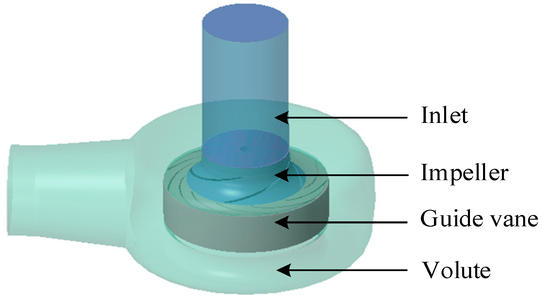
Figure 1 depicts the fluid calculation domain of the RCP.
Mixed flow pumps have a specific speed ranging from 300 to 500, while axial flow pumps range from 500 to 1200. The specific speed of the RCP examined in this study is 461, which can be either an axial or mixed flow solution at this parameter. Axial flow pumps operate based mainly on the basic theory of lift forces in fluid mechanics. When the centrifugal impeller runs at high speed, the fluid in the casing is primarily subject to the radial lift force of the impeller to perform work. The design method of traditional mixed flow pumps is basically the same as that of centrifugal pumps. It does not take into account the influence of the radial lift forces on the fluid in the impeller, while the fluid in the impeller of mixed flow pumps is subject to both centrifugal and radial lift forces.
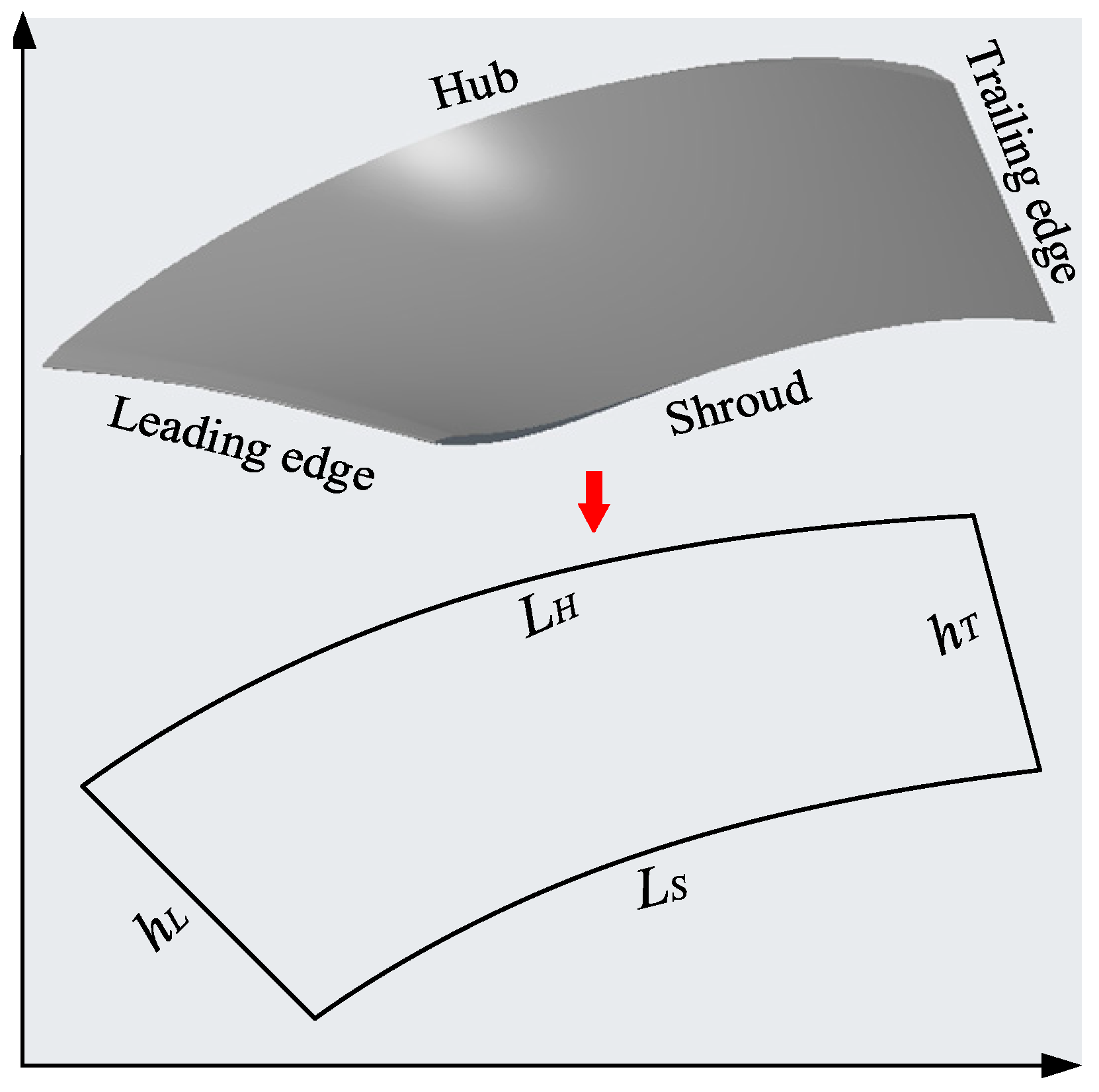
The geometry parameters of axial flow pump impellers mainly consist of chord length, outlet diameter, pitch, blade overlap coefficient, inlet and outlet angles, and hub ratio. This study incorporates the design philosophy of axial flow pumps and axial flow impeller design by treating the blades as made up of infinite arcs. The vanes are unfolded to examine the impact of impeller blades on the hydraulic performance of RCP concerning arc length (chord length and blade overlap coefficient), blade height (outlet diameter and hub ratio), and the interaction between them.
The
K1 factor is used to represent the arc length on the horizontal plane, while the
K2 coefficient is introduced to correct errors resulting from the angle of repose and to make the arc length on the horizontal plane more accurate. The
K2 coefficient accomplishes this by adding an import/export width difference parameter, thereby converting a planar arc length into a spatial arc length, as illustrated in
Figure 2. The arc length is calculated using the following formula:
where φ is the pack angle of the impeller blade;
K1 and
K2 are the correction factors;
K1 is 1.9274,
K2 is 0.5246;
D1,
D2 are the inlet and outlet diameters of the impeller;
β1, and
β2 are the inlet and outlet placement angles of the impeller;
b1 and
b2 are the inlet and outlet widths of impeller;
LH is the hub length;
LS is the shroud length;
himp is the blade height;
hL is the leading edge length;
hT is the trailing edge length; and
L/himp is the ratio of arc length to blade height.
From Formula (1), we can see that the L and himp are mainly determined by φ, D1, D2, β1, and β2. β1 and β2 are mainly determined by the velocity triangle of the blade inlet and outlet and are thus kept constant; b1 is mainly determined by the impeller inlet diameter and has a set value. Therefore, for mixed flow impeller blade types, the L and himp are mainly controlled by φ and b2.
This study utilized an orthogonal test design with 20 different combinations of pack angles ranging from 105° to 125° and outlet widths of 95, 99, 103, and 107. The aim was to investigate how the
L and
himp affect the performance of RCPs. The design scheme for the orthogonal tests is provided in
Table 2.
In this study, entropy production theory is utilized to analyze the distribution of hydraulic losses and the extreme value region of flow losses within the RCP. As the medium being transported is water, it is less affected by temperature changes, so the heat transfer effect can be ignored. Only the specific entropy generation rate
Spro,DT caused by the dissipation effect is considered. The internal flow dissipation loss of the RCP is much greater than the wall loss. Therefore, the specific entropy generation rate caused by wall friction is ignored, and the specific entropy generation rate in a turbulent flow
Spro,DT is mainly composed of the specific entropy generation rate caused by the time-averaged movement and the fluctuating terms. It can be expressed as
The expression for the entropy generation rate caused by the time-averaged movement is
The expression for the entropy generation rate caused by the fluctuation velocity is
However,
Spro,D’ is still an unknown term but may be related to the turbulence model [
16]. According to Kock’s entropy production theory [
17], the entropy generation rate caused by the fluctuation velocity is defined as
The total entropy production of the calculated domain is the volume integral of the dissipation specific entropy generation rate.
SD can be expressed as
where
μ is the dynamic viscosity;
ε is the turbulent dissipation rate;
u,
v,
w are the components of the velocity of the mass in a right-angle coordinate system; and
T is the temperature of the fluid mass.
This study utilised the
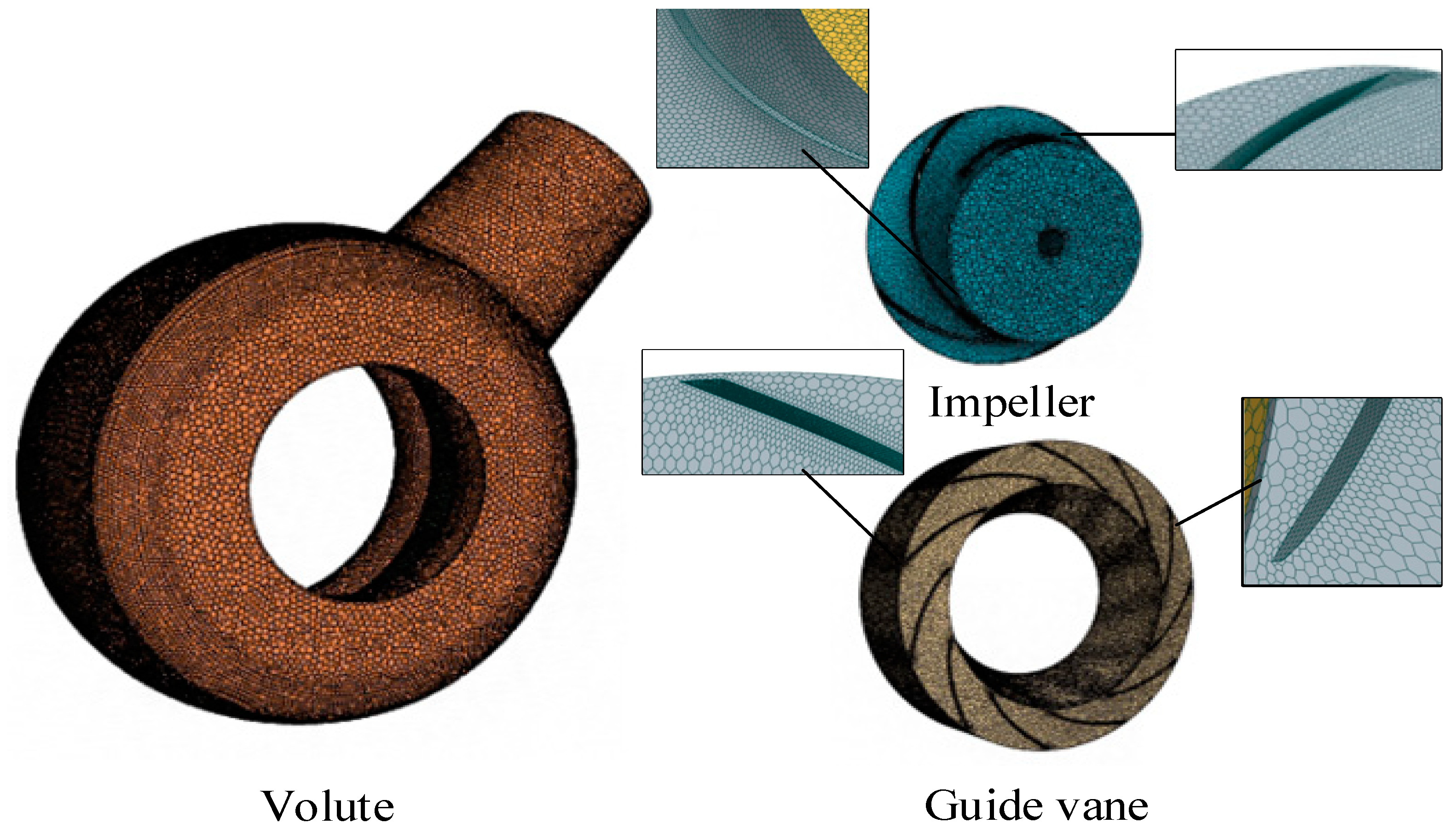
STAR-CCM+ software’s built-in mesh generation module was utilized to generate the mesh. The surface mesh generator model uses the surface remesher and automatic surface repair, whereas the pyramidal mesh generator uses the polyhedral mesh generator. The boundary layer mesh generator selected the prism layer mesher and locally refined the blades of the impeller and guide vane. The mesh of the RCP is displayed in
Figure 3. The independence of the fluid calculation domain’s grid for the RCP was examined. Schemes 1 to 5 were established from sparse to dense in proportion of the number of cells for each scheme, as shown in
Table 3. When the number of cells reached 1,855,000, the change in RCP efficiency was less than 0.05%. Considering computational resources and the computational accuracy of entropy production, Scheme 3 was selected for numerical simulation.
The fluid medium used in the calculations was water at a temperature of 25 °C. It was assumed to be incompressible with a density of 997.561 kg/m3 and a dynamic viscosity of 8.8871 × 10⁻⁴ Pa∙s. The reference pressure was set at 101,325 Pa. The inlet boundary condition was set as a mass flow inlet while the outlet boundary condition was set as a pressure outlet. Interfaces were created for the contact surfaces of each adjacent component and were set as internal interfaces. The realizable k-ε two-layer turbulence model was utilized as the turbulence model with a computational convergence accuracy of 10−4.
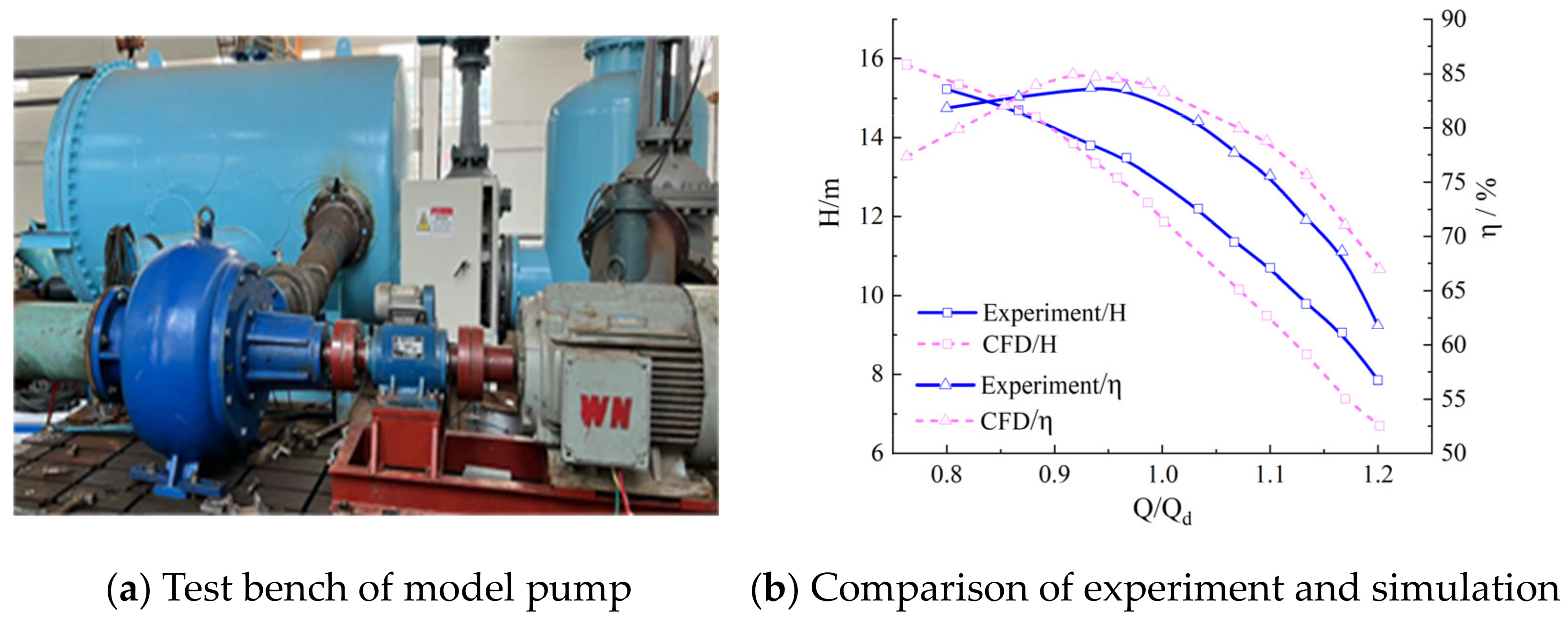
Figure 4a displays the test bench photograph, which includes equipment such as a pressure transmitter, force sensor, torque meter, DN350 electromagnetic flow meter, and pressure sensor. The accuracy of the pressure transmitter is ±0.1%, the accuracy of the torque meter is ±0.02%, the accuracy of the DN350 electromagnetic flow meter is ±0.5%. By using the pump unit comprehensive error, the overall performance of the pump unit system can be evaluated, and the efficiency comprehensive error of the pump unit system can be obtained based on the systematic error and random error of the pump unit system. The accuracy error of the pump unit efficiency in this experiment is ±1.48%, which meets the precision requirements of GB33216-89B level and ISO/DIS5198A level, indicating that the experimental results are reliable.
Figure 4b shows a comparison between the experiments and simulations. As the simulation and test results exhibit a consistent trend with an error of less than 5%, the simulation data are deemed reliable.
3. Results
The external characteristics of the 20 orthogonal design models are listed in
Table 4. It is evident from the table that the efficiency under large flow conditions aligns with the trend of head change, which is primarily influenced by the
L and
himp. There is little variation under small flow conditions, while under the design flow condition, the efficiency (
Ef) changes slightly but there is a significant change in head. The 5th, 6th, 10th, 11th, 15th, and 16th models exhibit an extensive variation range, with all parameters exhibiting an increasing trend except for the efficiency under the design flow condition. The head also rises when the
L is kept constant and the
himp is increased. On the other hand, when the
himp remains unchanged and the
L is changed, the head (
H) drops. Each group of models maintains a fixed
himp and varies the φ design within the range of 105° to 125° in five-degree increments. Comparing the
H of the 1st, 6th, 11th, and 16th models, which have different
himps but the same
L, shows that all have a consistent upward trend, and the efficiency curve also shows a constant upward trend.
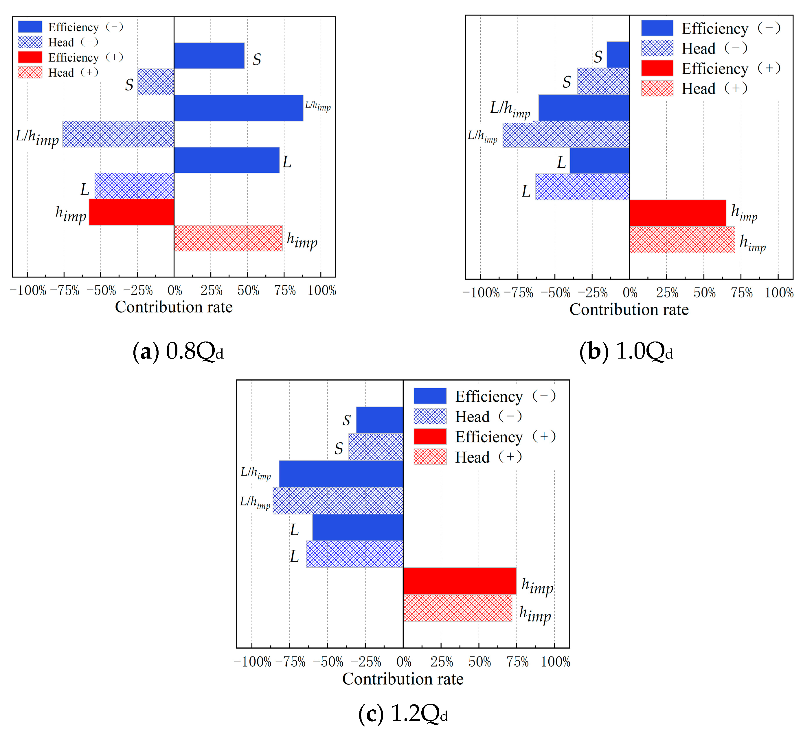
A correlation analysis was conducted to investigate the relationship between the geometric parameters of the impeller, including
L,
himp,
L/
himp and
S, with efficiency and head performance.
Figure 5 indicates that
S has a weak correlation with efficiency and head performance, while
L and
himp have a strong correlation with efficiency and head performance. Under both 1.0Q
d and 1.2Q
d conditions, the impact of each factor on head and efficiency is similar. Specifically,
L,
L/
himp and
S are all negatively correlated with head and efficiency, whereas
himp is positively correlated with head and efficiency. Moreover, the contribution of each geometric parameter to head and efficiency can be ranked as follows:
L/himp >
himp >
L >
S.
Under the 0.8Qd condition, each factor has opposite effects on efficiency and head performance. Specifically, L, L/himp, and S positively affect efficiency, while the head is negatively correlated with them. The contribution of each geometric parameter to efficiency can be ranked as follows: L/himp > L > himp > S; and for head performance, the order is L/himp > himp > L > S. Based on the correlation analysis, it can be concluded that smaller L/himp and higher himp lead to higher efficiency and head performance under design flow and large flow conditions. However, larger L/himp and lower himp under small flow conditions result in higher efficiency and lower head performance.
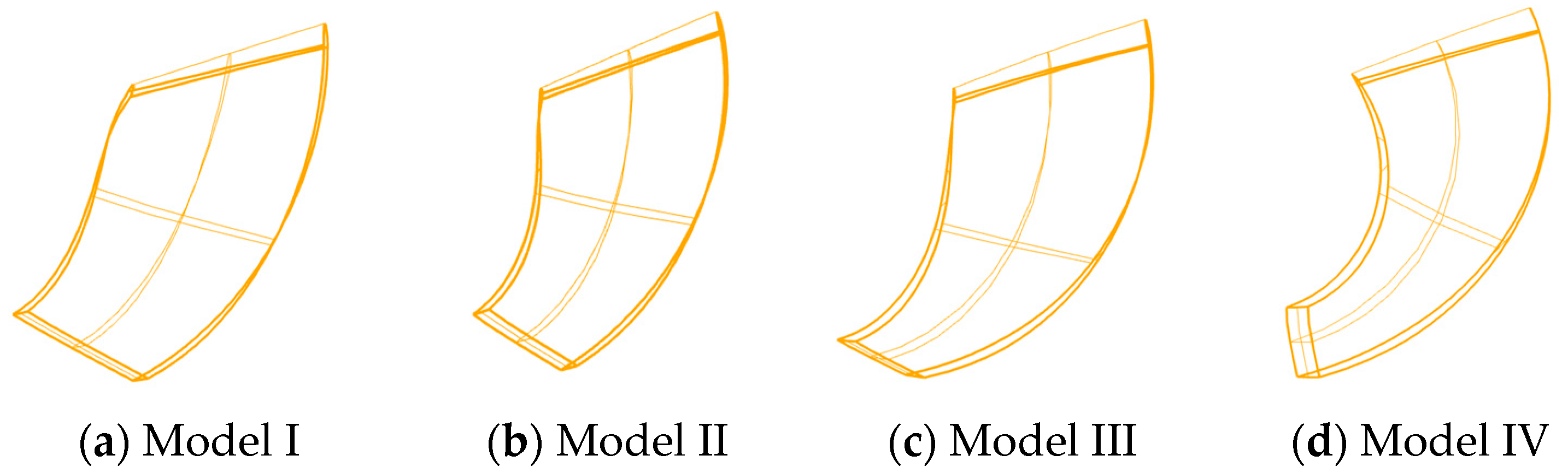
The head and efficiency indicators of twenty impeller models were comprehensively analyzed under different flow conditions, and four impeller models with different
L/
himp,
L, and
himp were selected to analyze these parameters’ effects on the RCP’s work and influx energy conversion mechanism. The selected models were Model 6, 8, 16, and 18, as shown in
Figure 6, and named Model I, II, III, and IV, respectively. By comparing these models, analyzing constant
himp, increasing
L, and larger
L/
himp, it was found that the efficiency increased at both small flow conditions and design flow conditions, while the efficiency at large flow conditions tended to decrease significantly. When the
L remained unchanged, and the
himp decreased, the efficiency increased under small flow conditions but decreased under design flow conditions and large flow conditions.
4. Discussion
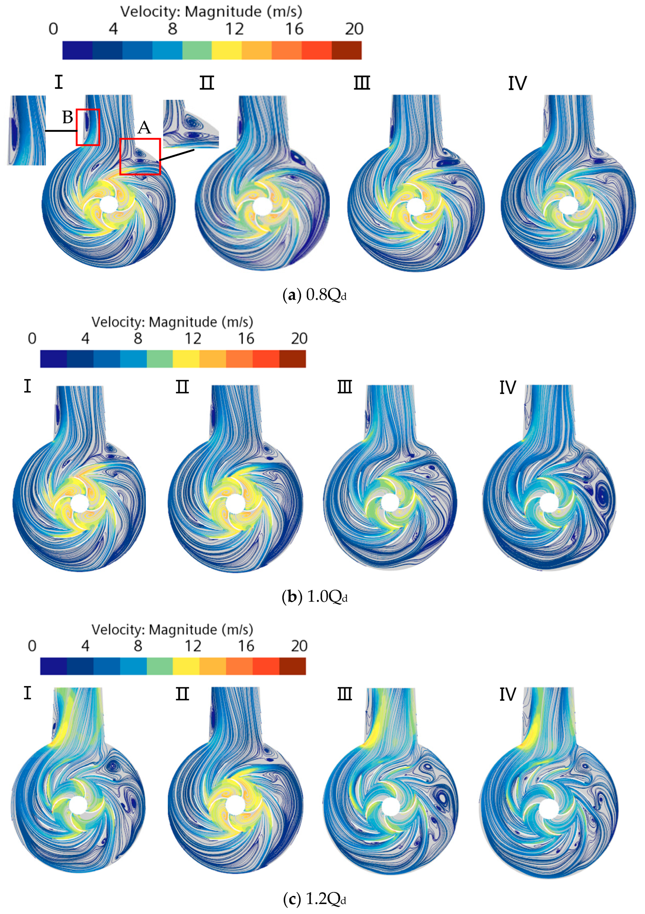
Figure 7 presents the axial velocity streamline of the RCP under different conditions. A significant number of low-velocity vortex groups can be observed inside the spherical volute, mainly distributed downstream of the volute (A) and the inner part of the diffusion segment (B). Under small flow conditions, the flow in the pump casing is more uniform, with fewer vortex groups and higher flow velocities in the impeller and guide vane flow paths. Models I and III have shorter
L and larger velocity gradients within the impeller, resulting in significantly larger high-speed vortex groups that have a significant impact on the inlet side of the guide vane. The fluid outflow after the flow state of the guide vane is worse, and it has a more significant impact on the inner wall of the volute, forming a pronounced secondary flow and vortex groups in the volute.
Model IV impeller exhibits significantly smaller vortex groups at high velocities in the impeller flow path with more uniform velocity gradient changes. As a result, the fluid follows a better streamline after entering the guide vane and volute, leading to smaller vortex groups in the A and B zones. Therefore, under small flow conditions, the impeller is slender (with a large L/himp), and it can perform more adequate work.
Under the 1.0Qd condition, the Model I and II impellers exhibit obvious high-velocity vortex groups, and there is a high-velocity zone and boundary layer separation in the guide vane. However, the flow in the volute is significantly better, with an obvious low-velocity vortex zone in the B zone. The flow in the Model IV impeller is the best, but there is a large vortex in the volute, and there is backflow phenomenon at the guide vane outlet. At 1.2Qd, models I, III, and IV all have good flow patterns within the impeller, but there is reflux at the exit of the guide vane channel, a large number of vortex groups in the volute, and an obvious high-speed jet in the B zone. Model II has an obvious vortex group in the impeller, with high velocity backflow in the guide vane channel, but it performs relatively better inside the volute. At 0.8Qd and 1.0Qd conditions, Model IV has the best flow pattern with uniform velocity gradient changes within the impeller, resulting in the highest efficiency. However, at 1.2Qd conditions, Model IV has a large number of vortex groups inside the volute, leading to the lowest efficiency.
Based on the above analysis, it is evident that the L, himp, and L/himp of the impeller have a significant impact on the flow inside the RCP. A detailed analysis of dissipation losses within the impeller, guide vane, and volute flow channel of the RCP is necessary to assess the impeller’s influence on the flow inside the RCP and to gain a more comprehensive understanding of the work and energy conversion mechanism of the RCP impeller.
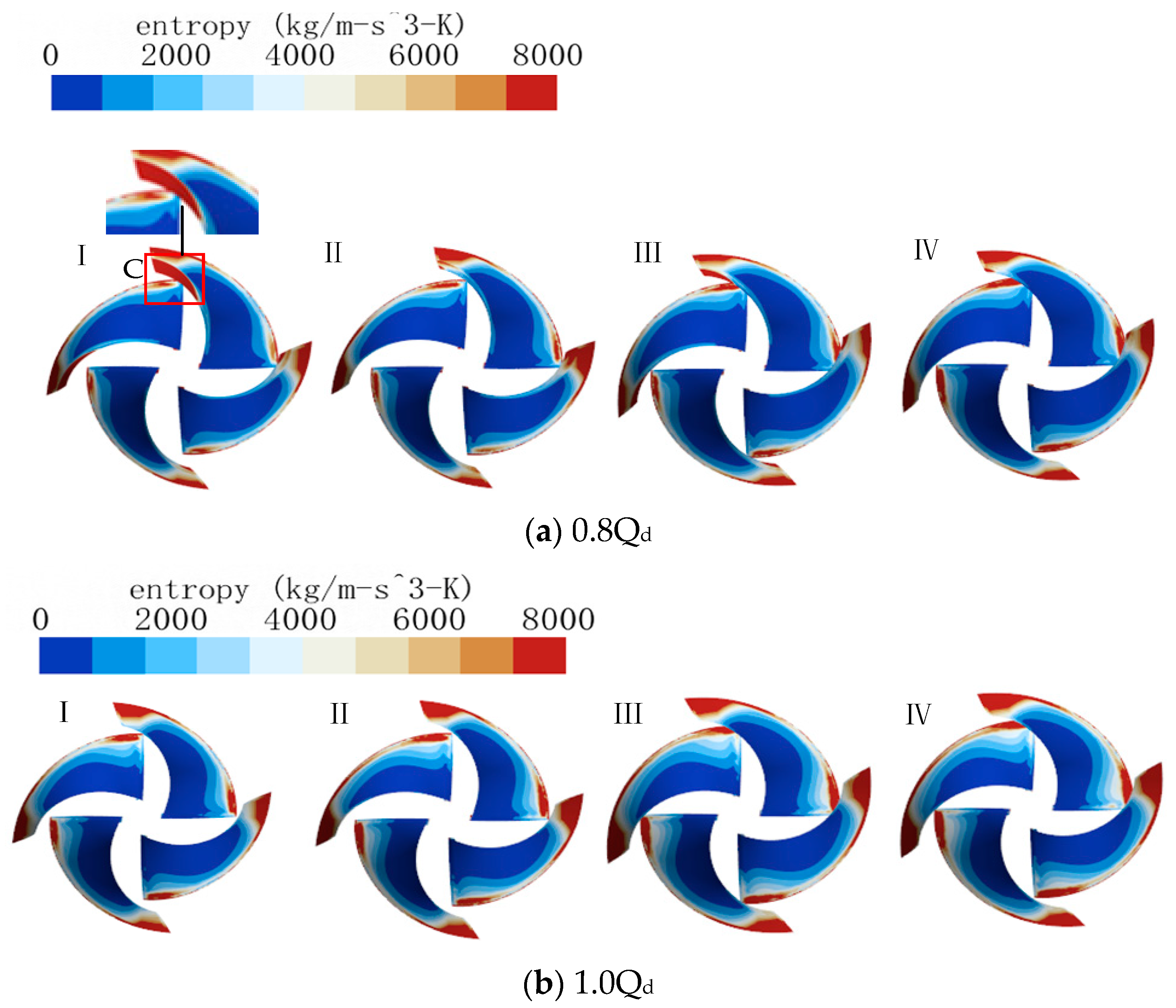
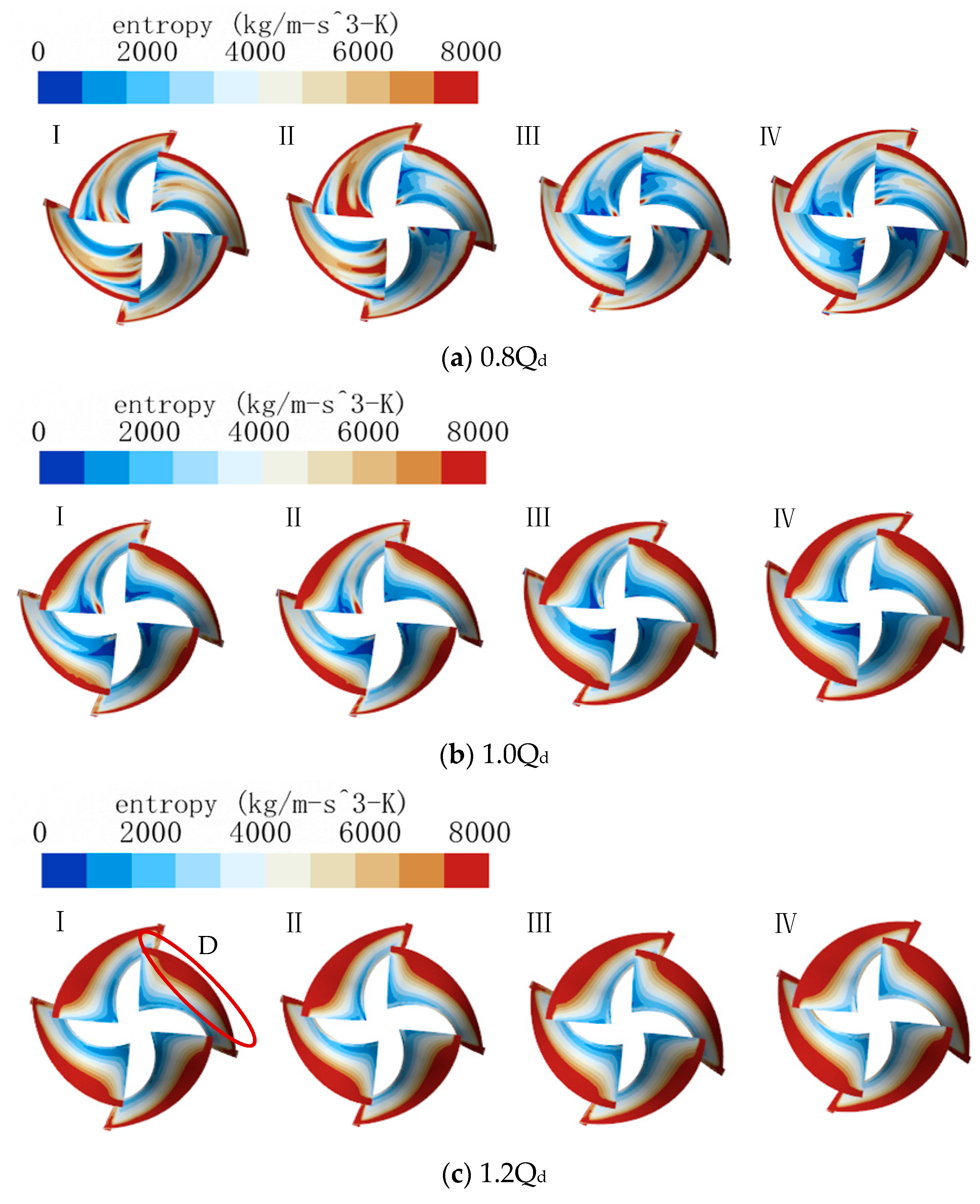
Figure 8 and
Figure 9 illustrate the entropy production distribution on the impeller’s working surface and suction surface. As depicted in
Figure 8, hydraulic losses on the blade’s working surface are primarily concentrated at the blade outlet and outer edge of the blade. As the flow rate increases, the fluid’s impact on the blade intensifies, leading to boundary layer separation and the generation of wake flow.
Consequently, there is an increase in hydraulic losses at the blade outlet and outer edge.
Figure 8a shows that at small flow conditions, the entropy production on the working surfaces of different impellers is concentrated near the blade outlet, specifically in the area close to the front cover. Moreover, the entropy production distribution on the suction surface is significantly greater than on the working surface. Model I and III blades have higher entropy production on the outlet edge’s inner (C) side due to fluid decoupling. In contrast, models II and IV exhibit less loss in the C zone and higher loss at the outlet close to the rear cover. As the
L increases and the
himp decreases, the flow channel narrows, causing the blades to be more constrained to the fluid.
Comparing
Figure 8 and
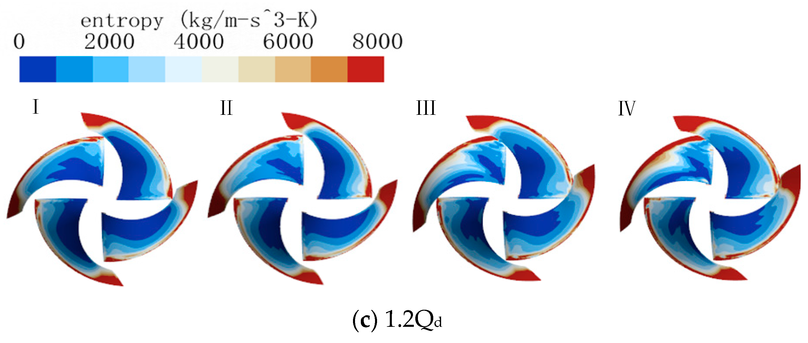
Figure 9, the hydraulic losses on the impeller mainly occur on the suction side of the impeller. Upon examination of
Figure 9’s entropy distribution diagram for the impeller’s suction surface, it becomes apparent that hydraulic losses at the outer edge of the blade (D) increase as the flow rate increases. Moreover, when the
L increases, hydraulic losses in the D zone increase due to hydraulic impact and friction losses. As the
L remains unchanged but the
himp increases, the hydraulic loss at the inlet of the impeller’s suction side decreases. Model II, with its smaller
L and
himp, has a greater blade curvature, resulting in a larger hydraulic loss at the inlet. At small flow conditions, secondary flow occurs at the blade inlet, creating a sizable area of hydraulic loss at the inlet due to the narrow flow path of Model II. At large flow conditions, the range of hydraulic losses in the D zone expands due to the rapid impingement and friction of the fluid.
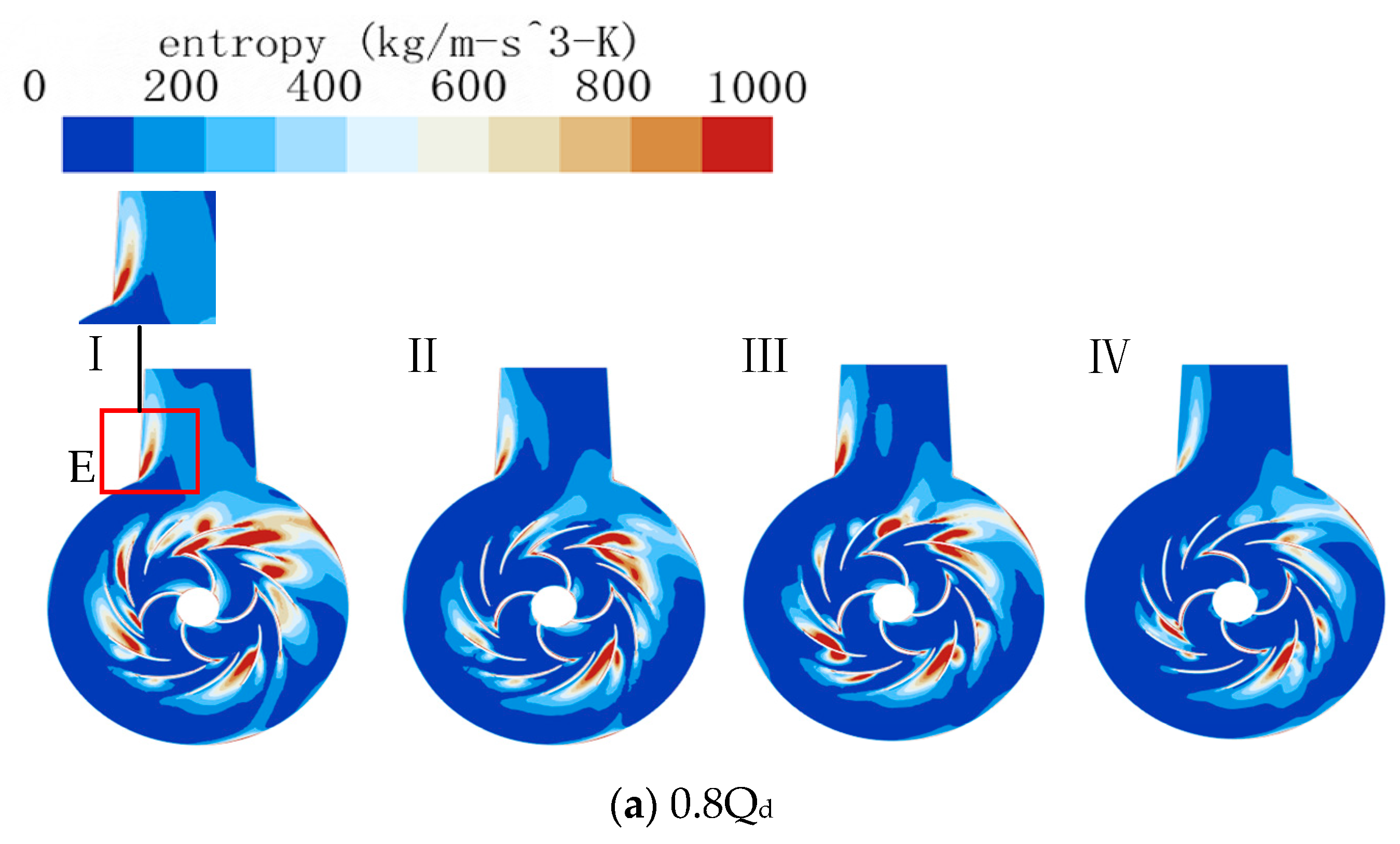
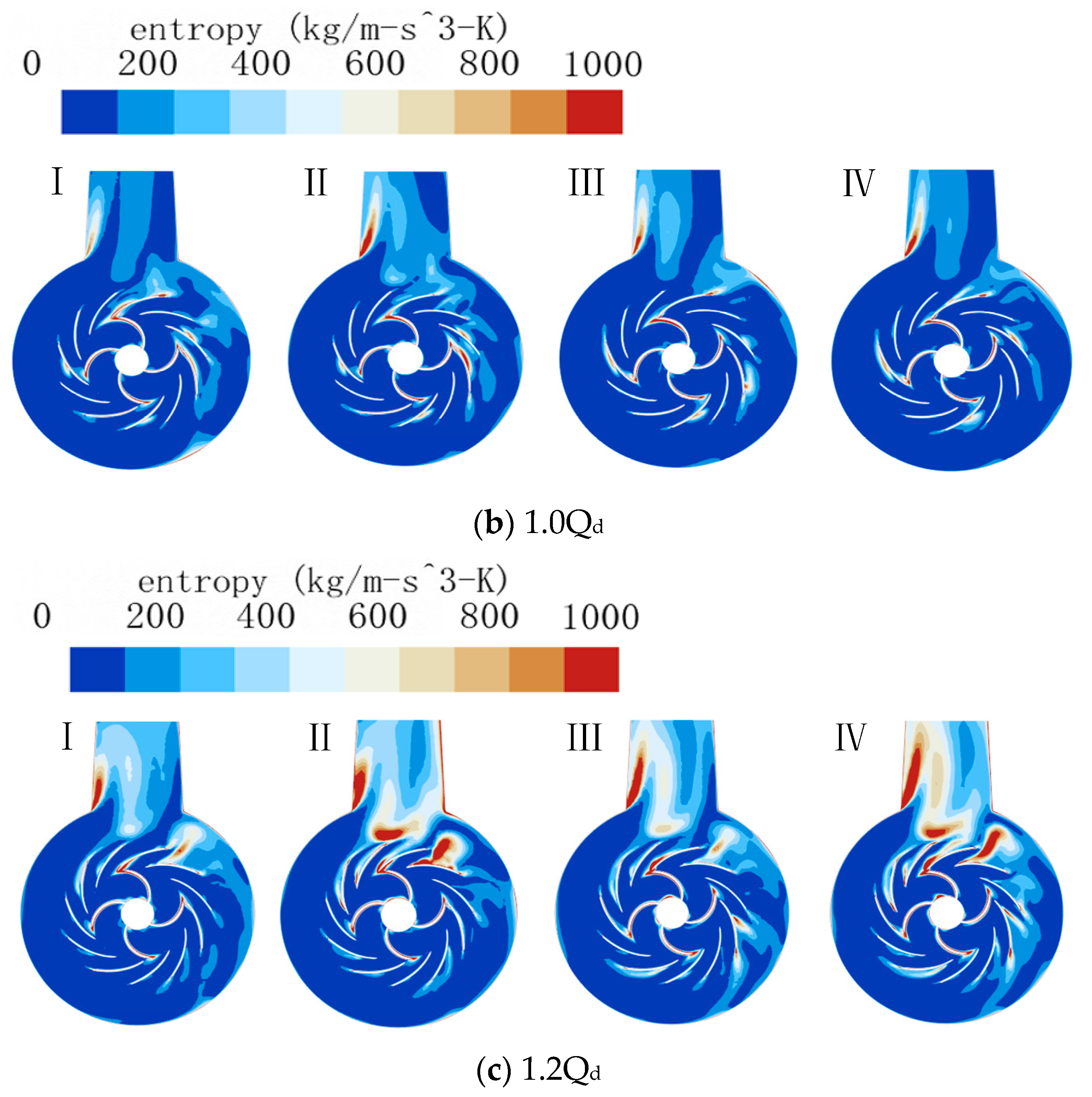
Figure 10 displays the entropy distribution of the axial section of the RCP, providing a visual representation of the internal hydraulic losses in the RCP. The area of the entropy generation rate distribution reflects the efficiency of the RCP, with larger areas indicating higher losses and lower efficiency.
Figure 10 shows that hydraulic losses within the RCP are mainly located at the impeller outlet, guide vanes, inner flow channel and E zone.
At 0.8Qd flow condition, the energy losses are mostly concentrated in the guide vane channel. At 1.2Qd flow condition, the energy losses concentrate at the E zone. Under 1.0Qd condition, the overall loss is small, but the loss in the guide vane channel of Model II is larger. Based on the aforementioned velocity flow field analysis, fluid is likely to experience turbulence when flowing along the guide vane channel, which can cause phenomena such as impact. These effects can lead to higher pressure areas in the local guide vane region.
For models I, II, III, and IV, the loss in the E zone increases with increasing L or decreasing himp. Model I has smaller losses in the E zone, but greater losses at the impeller outlet and the inlet of the guide vane. Model IV has the smallest entropy distribution area while Model I has the largest entropy distribution area under small flow conditions.
Due to the increased flow velocity at the impeller outlet of Model I, rotor-stator interaction occurs, resulting in larger losses at both the guide vane outlet and within the guide vane’s flow channel. To address this issue, increasing the arc length can result in more uniform flow in the pump, lower flow velocity at the impeller outlet, and reduced losses. By increasing the L, the flow in the pump becomes more uniform, flow velocity at the impeller outlet decreases and losses are reduced. When the L is unchanged and the himp is reduced, the flow velocity in the impeller channel decreases. This reduces the influence of static and dynamic blade interference, reducing guide vane channel losses. The highest efficiency occurs at an arc height ratio of 2.427, while the lowest efficiency occurs at an arc height ratio of 2.161.
Under large flow conditions, models II and IV experience greater losses due to their smaller impeller himp. When the fluid flows out of the guide vane and into the outlet section, mutual extrusion can occur, resulting in chaotic flow and causing higher losses. Additionally, losses increase at the corner where the volute connects to the exit section as the L/himp increases. Model I, with L/himp of 2.161, is the most efficient, while Model IV, with L/himp of 2.427, is the least efficient.
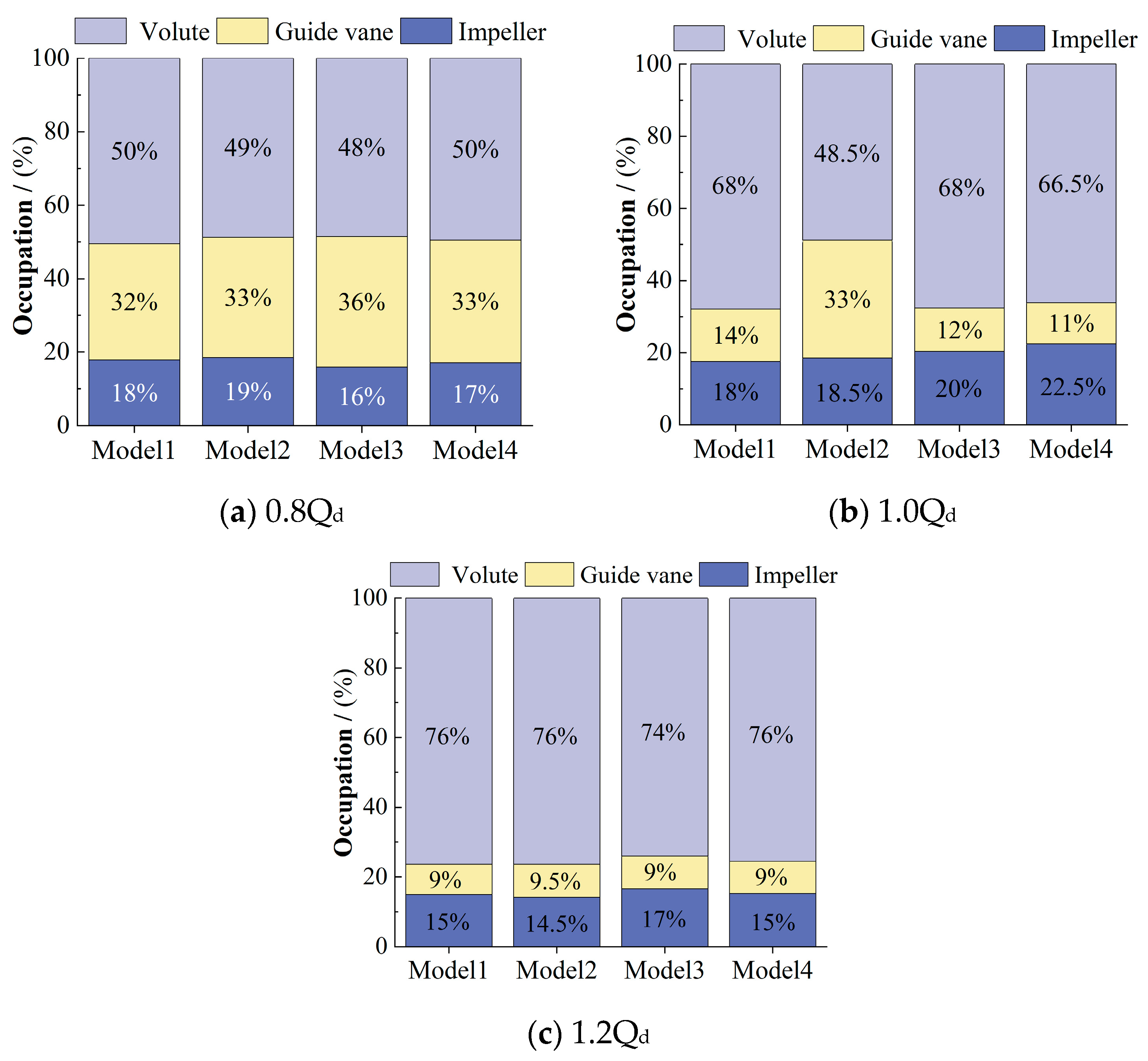
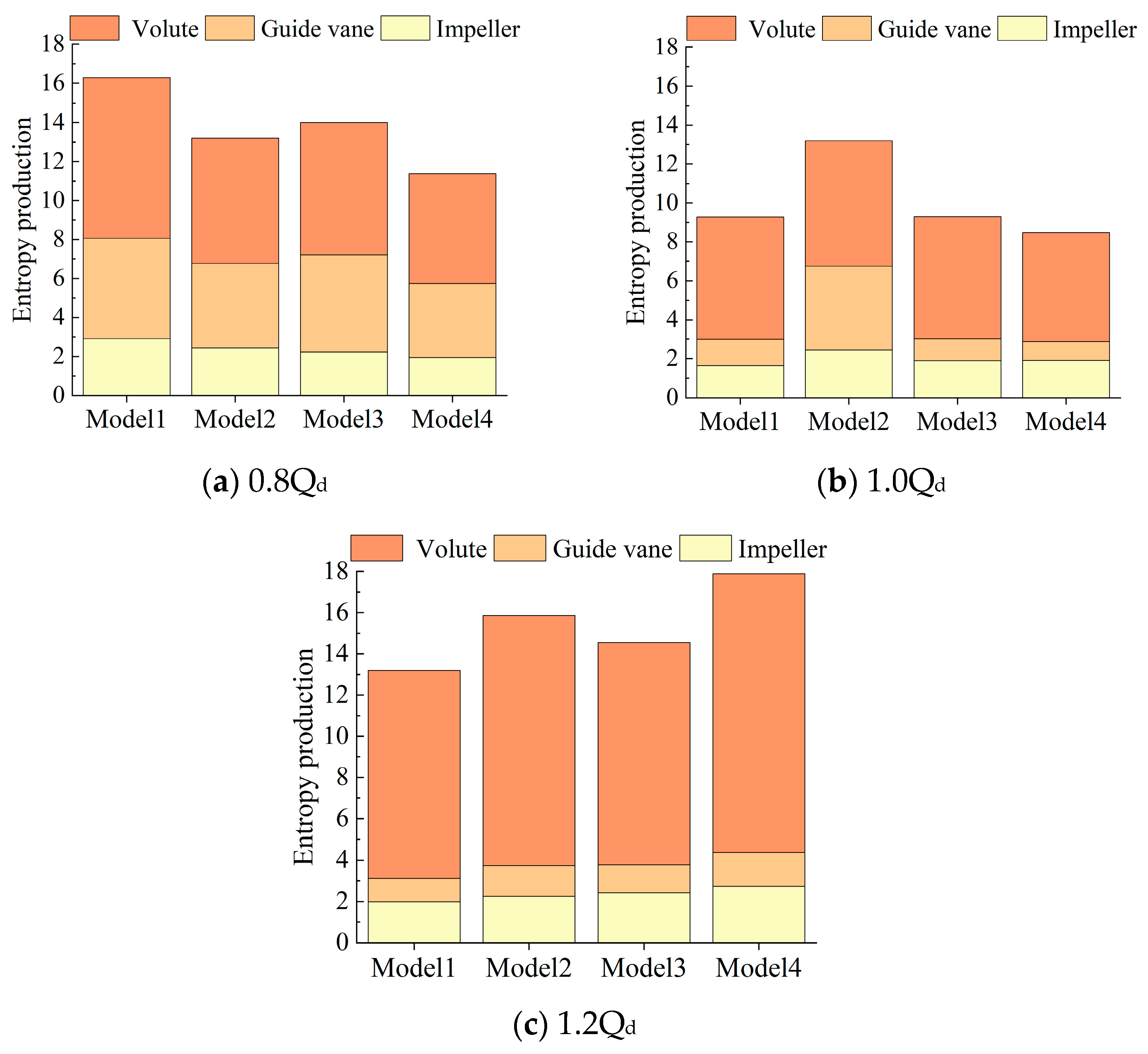
To further investigate the internal flow losses of the RCP under various flow conditions, the percentage of losses in each component of the RCP and the entropy production of each component was analyzed.
Figure 11 and
Figure 12 show that the flow loss in the volute is the primary contributor, and as the flow rate increases, the loss in the volute also increases. At 1.2Q
d condition, the entropy production in the volute accounts for as much as 76%.
When the flow rate changes from 0.8Q
d to 1.0Q
d, the proportion of entropy production of Model I and II impellers remains unchanged, while the proportion of entropy production of Model III and IV impellers increases. Although the proportion of Model I and II remains unchanged according to
Figure 12, the entropy generation rate of Model I impeller decreases, while that of the Model II impeller increases. This indicates that Model I is suitable for operation under 1.0Q
d conditions, while Model II, with its reduced
himp and narrower flow channel, is suitable for operation under low flow conditions.
The guide vane entropy production of Model I, III, and IV decreases greatly, indicating that the impeller and guide vane coupling is better. The fluid entering the guide vane can better fit the linear flow of the guide vane. On the other hand, the guide vane entropy production of Model II increases because the short and narrow impeller blade shape leads to a higher velocity of fluid entering the guide vane, causing impact losses to the guide vane.
As the flow rate expands from 1.0Qd to 1.2Qd, the impeller entropy generation rate decreases, and the actual entropy production value also decreases. The entropy production of the guide vane is smaller under large flow conditions. Still, the entropy production of Model II drops significantly due to turbulent flow occurring in the volute which increases losses.


