Article

Investigating the Reliability of the Location Transmitted by V-Pass Terminals: Prompt Rescue of Fishing Vessels

Department of Marine Police System, Gyeongsang National University, Tongyeong 53064, Republic of Korea
*
Author to whom correspondence should be addressed.
J. Mar. Sci. Eng. 2023, 11(5), 1023; https://doi.org/10.3390/jmse11051023
Submission received: 19 April 2023 / Revised: 5 May 2023 / Accepted: 9 May 2023 / Published: 11 May 2023
(This article belongs to the Special Issue Coastal Engineering: Sustainability and New Technologies)

Abstract

:
Fishing boats are equipped to quickly rescue ships and save lives in the event of an incident at sea; therefore, determination of the incident location is imperative for a swift response. According to the 2021 marine accidents by ship use statistics, fishing and non-fishing boats accounted for 64.6 and 35.4%, respectively, of the total 3053 ships involved in an accident. In addition to V-pass and the Automatic Identification System (AIS), several other types of terminals exist; however, approximately 91% of all registered fishing boats use V-pass terminals. Therefore, it is essential to know the exact location of fishing boats. However, little research has been conducted on V-pass equipment. Therefore, in this study, marine experiments were conducted using V-pass and AIS terminals that are mainly used in fishing boats. To determine the exact location of an incident and rapidly respond and rescue, this study compared the data saved in the terminals with the data received by the Vessel Traffic Service center. In the event of a maritime incident, the radio shadow areas and causes of the error in the location transmitter must be investigated to quickly rescue the fishing boat and to determine the root cause of the incident, respectively.

1. Introduction

According to the 2021 marine accidents by ship use statistics, fishing and non-fishing boats accounted for 64.6 and 35.4%, respectively, of the total 3053 ships involved in an accident, with 416 out of 512 casualties occurring on fishing boats [1].
To ensure the prompt rescue of individuals in fishing boat accidents, fishing boat location transmitters must be installed and operated in accordance with the “Fishing Boat Act,” “Fishing Boat Act Enforcement Regulations,” and “Notice on the Installation Standards and Operation of V-pass Devices” No. 2018-6 issued by the Korea Coast Guard.
As reported in the literature [2,3], 91.2% of the 61,717 registered fishing boats, that is, 56,279 fishing boats, operate V-pass terminals, of which 29,880 boats exceed 2 t, whereas 47% of the boats are under 2 t. This onboard location-tracking infrastructure currently does not comply with the requirement that ships with automatic identification system (AIS) devices be installed under the Ship Safety Act, which is applicable for passenger ships, oil tankers, and most other ship types with a minimum gross tonnage of 2, 50, and 300 t, respectively.
As revealed by the ship tracking information received by the ship detection system (Vessel Traffic Service; VTS) of the Marine Traffic Control Center, the final location data transmitted by fishing boats, which is used for investigating the incident factors, is stored 4–6 min before the incident.
The V-pass terminal is a system that records navigation data for periods of 4 and 6 min and subsequently transmits the data cumulatively. However, the navigation information between 30 s and 6 min is not saved depending on the time of the incident. Subsequently, the tracking information saved in the V-pass terminal installed in the stricken ship is directly extracted and used for incident analysis.
Notably, no prior research has been conducted to validate the location accuracy of V-pass terminals, and the current research on the tracking data and system is limited, except for certain studies reported in the literature [4,5,6,7,8,9,10,11,12].
This study compared the data saved in the V-pass terminal with the data received at the VTS through a sea test of the V-pass and AIS terminals installed on a test ship, and examined the transmission cycle and save interval. The location of AIS terminals was compared with that of numerous previous studies and the location of V-pass terminals, of which there is limited existing research data, to determine the frequency of location errors.
Section 2 presents the experimental details and compares the location-tracking capabilities of the V-pass and AIS terminals. Section 3 presents the results of this study obtained through the aforementioned test methodology. Section 4 proposes plans for the improvement of the identified problems based on the study findings. Section 5 presents the conclusions of this study and provides scope for future research.

2. Methods

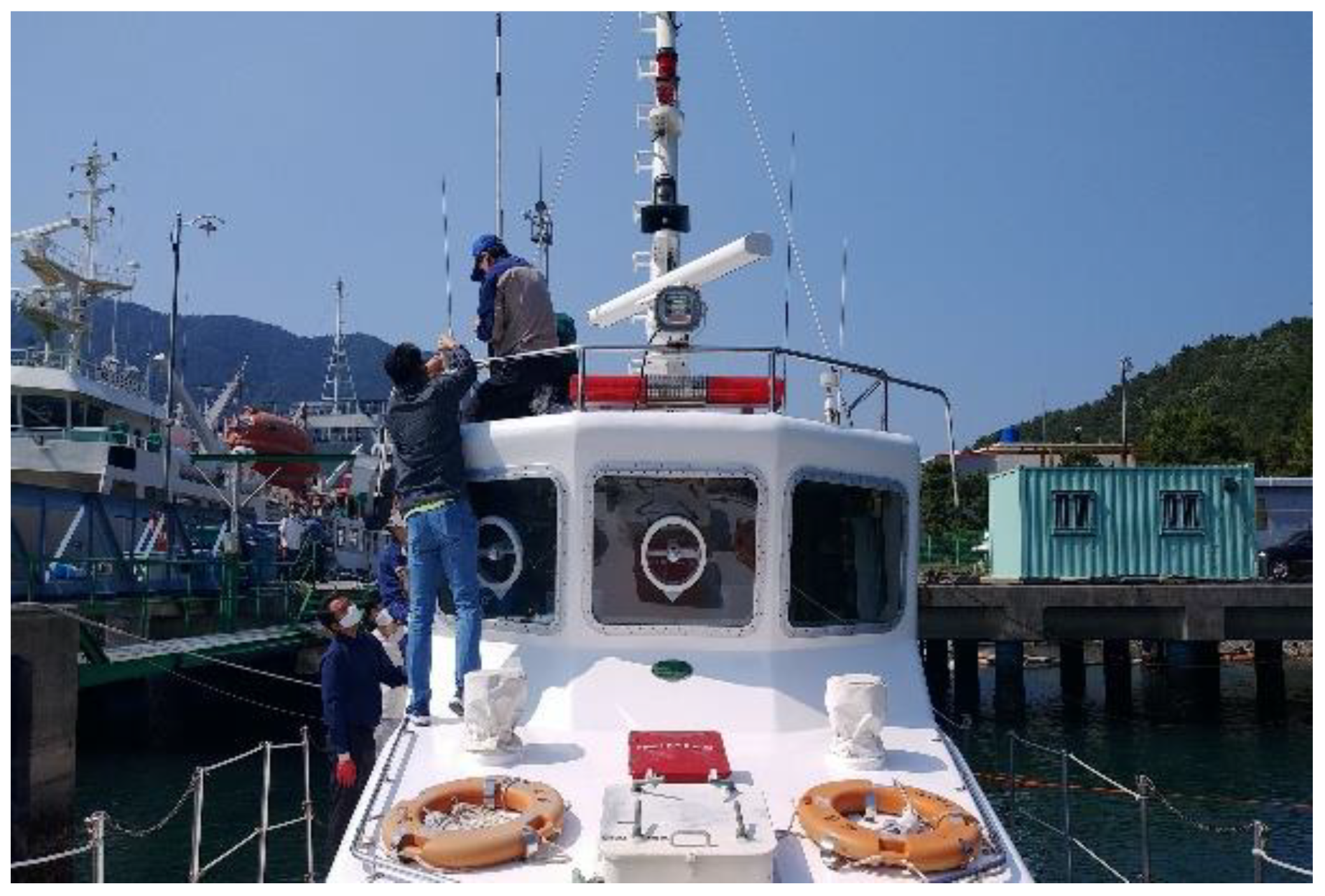
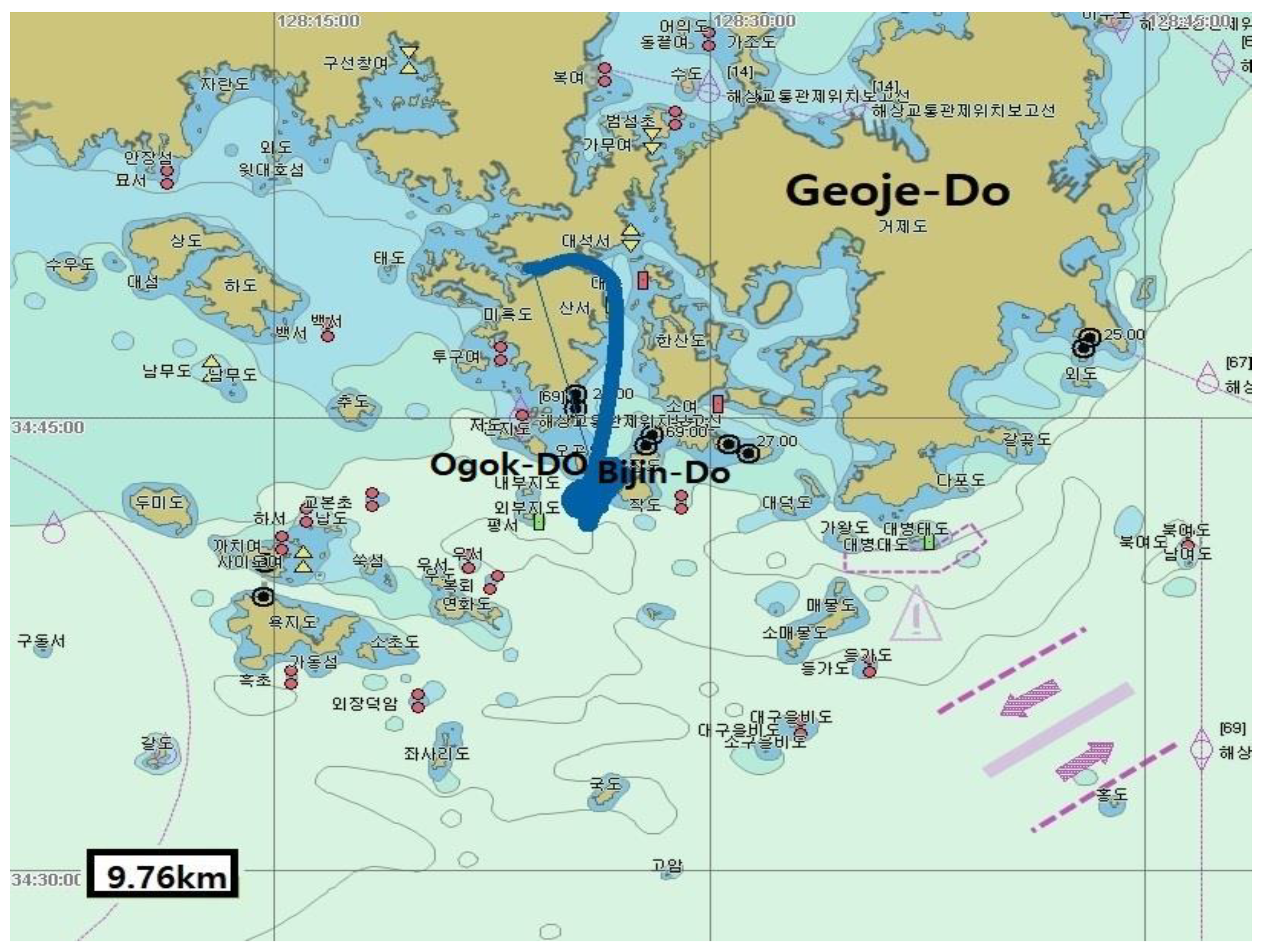
Test Details and Procedure

The sea test was conducted on 9 June 2022 using V-pass (Samyung ENC, SPA-900) and AIS (Samyung ENC, AIS-50N, class B) terminals installed on the marine survey ship, Chambada, of Gyeongsang National University, and the experimental track connected Tongyeong port and Bijin-do island in Gyeongsangnam-do.
The V-pass terminal installs a location-transmitting device on a fishing boat to establish a rapid response system for marine accidents and has an SOS function. The main function of the terminal is to transmit and receive the location of boats for rapid response to incidents and emergency situations. When the SOS button on the terminal is pressed or the transmission/reception antenna is separated, an SOS notification is automatically transmitted to the Korea Coast Guard situation room.
Additionally, it is linked to the automatic ship departure and entry system; therefore, it is possible to report departure and entry without visiting the police box or branch office. The marine survey ship, Chambada, has a gross tonnage of 36 t and is 23.14 m in length, which are similar to those of inshore fishing boats [13]. Therefore, the experimental environment was similar to the transmission conditions of a location transmitter installed on an actual fishing boat. The maritime weather during the test was relatively clear with wind speeds of 5–8 m/s, and maximum and average wave heights of 1.5 and 0.6 m, respectively.
As per the test procedure, the tracking save intervals for the V-pass and AIS terminals were set to 5 s, which saved the data received by the Tongyoung coastal VTS and the data transmitted from the terminal while sailing and turning in the sea area near Bijin-do. Each track was analyzed by comparing the positions indicated on the electronic charts of the ship collision reproduction system [14,15,16]. The ship collision reproduction system is a system used by the Korea Coast Guard to reproduce real-time ship movements by entering the trajectory data of the ship to analyze ship collisions. It was created through the National Research and Development Project of the Korea Coast Guard from 2014 to 2017. In this study, V-pass and AIS data obtained through sea trials were input into the ship collision reproduction system and compared by displaying them on the electronic chart.
As illustrated in Figure 1, the V-pass and AIS antennae were installed at the same position above the wheelhouse of the test ship to minimize errors owing to the antenna position.
Figure 2 presents the geographical positions and tracks of Gyeongsangnam-do, Tongyoung City Bijin-do, and Ogok-do, where the sea trials were conducted, on an electronic chart.

3. Results

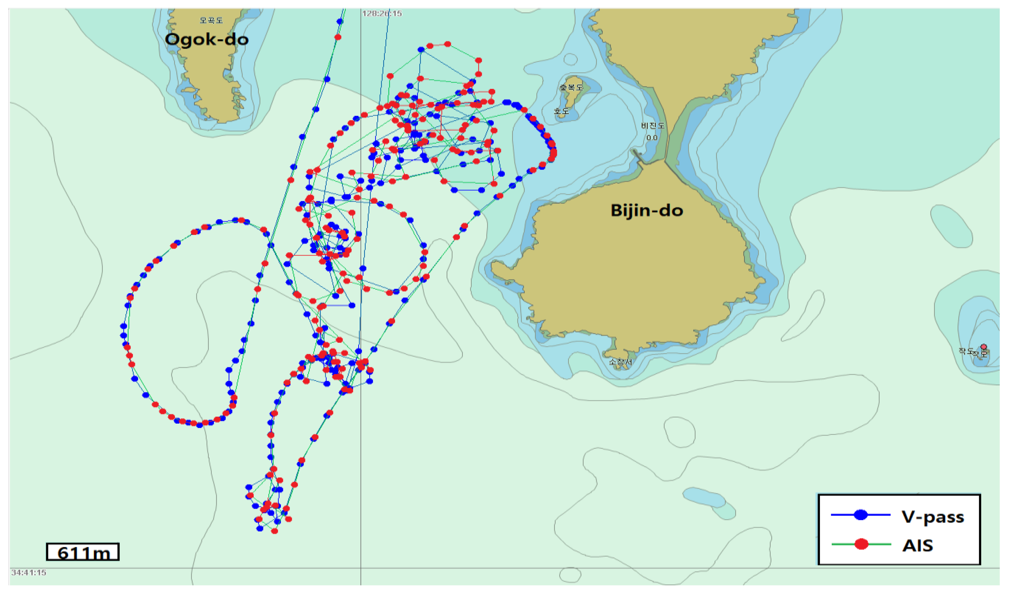
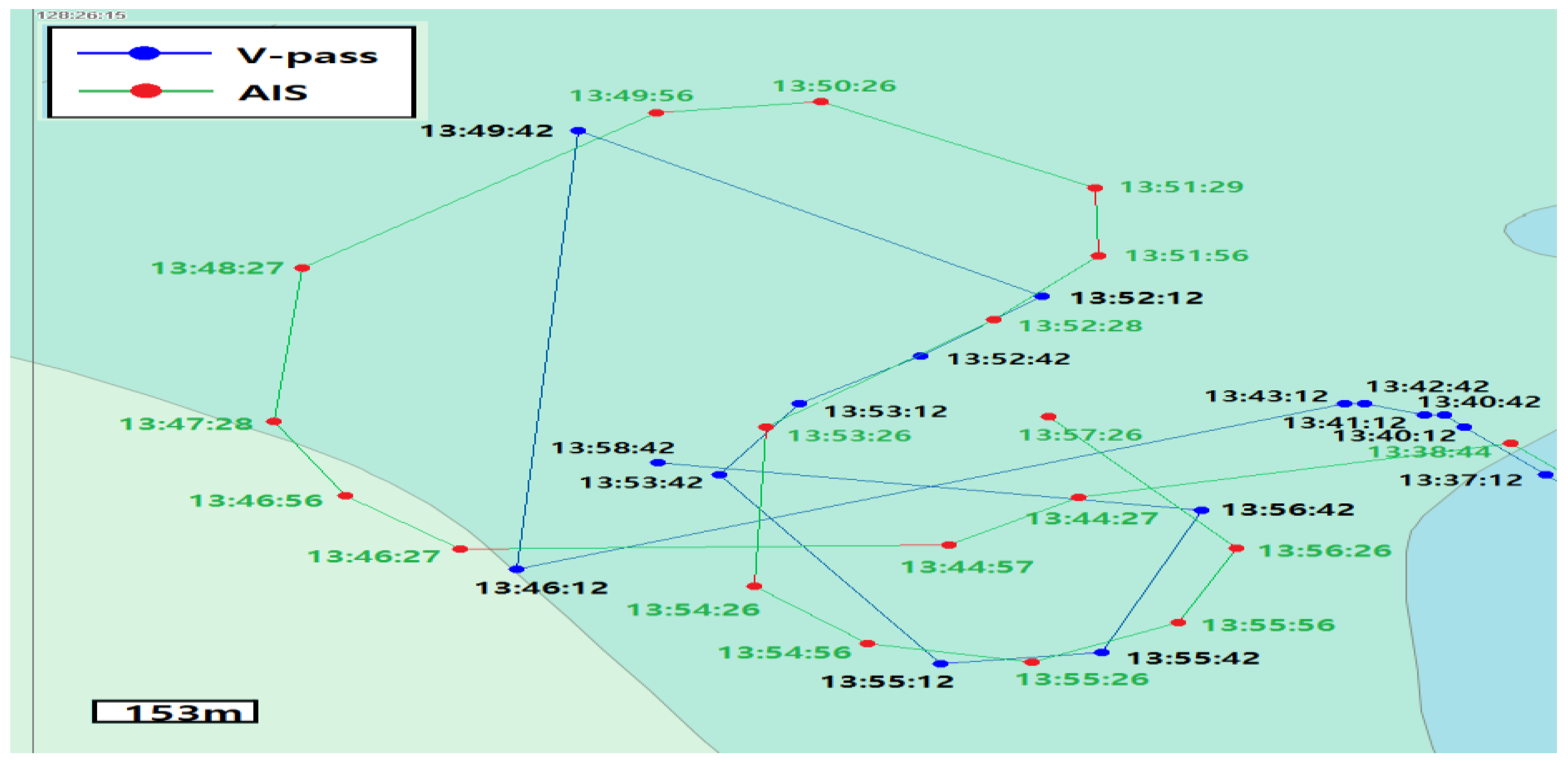
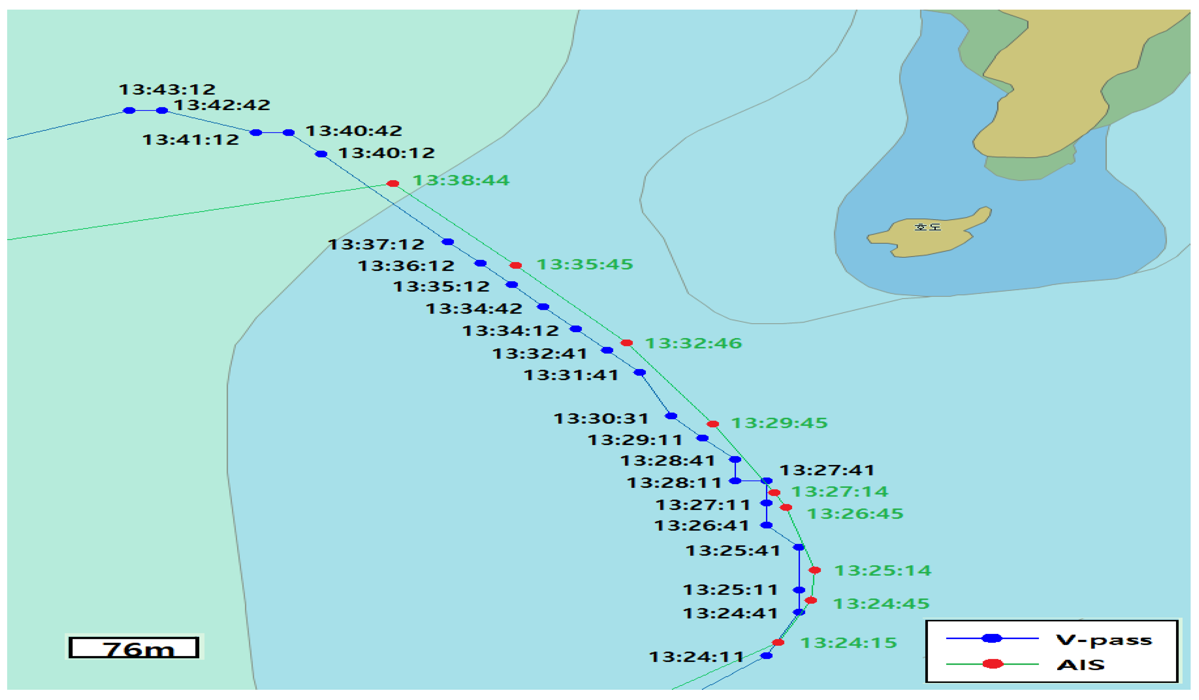
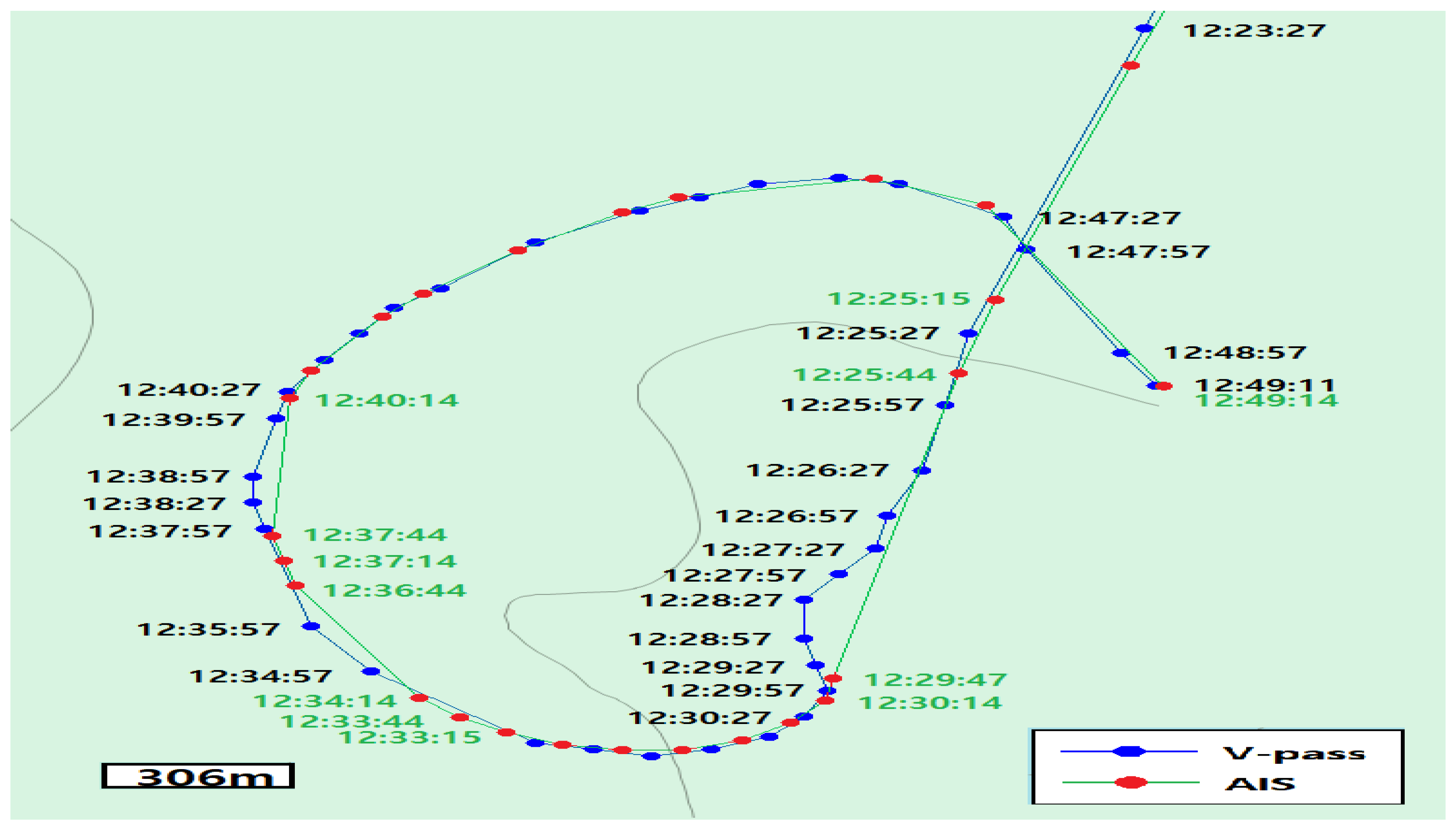
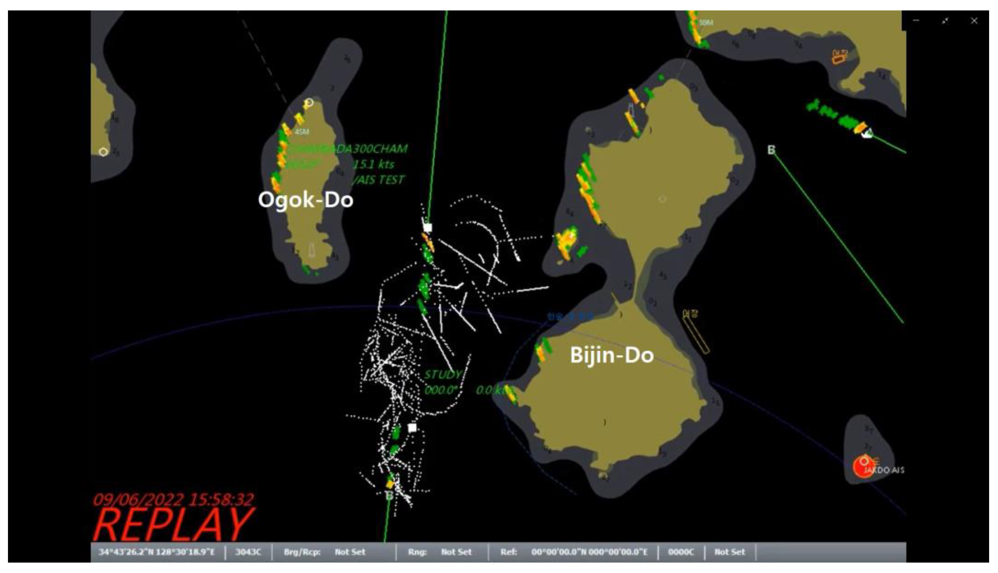
3.1. Comparison of the V-Pass and AIS Data Received by VTS

The data transmitted by the V-pass terminal (time zone, location, and received by VTS according to time) were compared to that transmitted by the AIS terminal. The number in the rectangles in the lower left corner of the electronic charts represents the distance scale for the horizontal length of the rectangle.
Figure 3 displays the V-pass and AIS data received by VTS from approximately 11:46 (KST) to approximately 15:53 on an electronic chart. In the test, which lasted approximately 4 h, the VTS received 269 and 223 instances of V-pass and AIS data, respectively.
The state of navigation, anchor, and changing speed in the V-pass data transmission cycle clearly did not change. These data were set to transmit in regular intervals of 30 s. Furthermore, in a particular period, the data interval was 1–7 min 30 s owing to missing data.
The reporting interval criteria for the AIS data was set to those specified in ITU-RM.1371-4 (International Telecommunication Union), which is dependent on the type of AIS class and the dynamic conditions of the ship. Class A (as mentioned in Table 1) is mainly used for international sailing vessels. The criteria in class A, such as the ship speed and course change, are more subdivided than those in class B (as mentioned in Table 2), and the reporting interval is shorter.
Because domestic fishing boats, excluding deep-sea fishing boats, mainly use class-B terminals, the experimental data was compared using the criteria in Table 2. The class-B terminal has a reporting interval of 30 s when the dynamic conditions of the test ship are 2–14 knots; the speed of the experimental boat was 1–14 knots. Therefore, a reporting interval of 30 s or 3 min is required depending on the speed condition.
The data was transmitted every 30 s, and the transmission data in certain sections was missing, similar to that observed for the V-pass data. In a particular period, the data was not transmitted for 1–7 min. The transmission characteristics did not deviate from the technical requirements stipulated in the Regulations on Installation Standards and Operation of Transmitting Devices, that is, every transmission was performed at intervals of 10 min or less in this experiment. Figure 4 shows three and fourteen packets of V-pass and AIS data, respectively, transmitted during a linear cruising section lasting approximately 9 min, which is a considerable difference in the number of data packets received by VTS. The AIS data was relatively regularly transmitted at intervals of 30 s–1 min, whereas the V-pass data was not transmitted for up to 7 min 30 s and the intervals between the transmission points were irregular.
Non-storage or non-transmission of trajectory data for tens of seconds to several minutes in a linear section without speed or course changes is not problematic as the location or direction of progress over time can be predicted.
Figure 5 shows 16 and 19 V-pass and AIS data packets, respectively, for a period of approximately 20 min in a specific section of a non-linear track. Although no significant differences were observed, the AIS data was regularly received within 1 min 30 s of a turn, except for the initial track corresponding to a period of 5 min 30 s when drifting to navigation, whereas the V-pass data was received within 30 s of a turn. Clearly, the V-pass data was irregularly transmitted up to 3 min 30 s.
If the trajectory data in a non-linear section is not transmitted for tens of seconds to several minutes, as shown in Figure 5, the location of the ship over time cannot be determined. Moreover, its direction of travel and turning circle cannot be determined.
Figure 6 presents a comparison of the trajectories in a specific section of a linear track lasting for approximately 19 min. The number of V-pass data packets (23) received by the VTS was greater than the number of AIS data packets (9). Thus, the V-pass data received was >2.5-fold greater than the AIS data.
According to the AIS class-B nominal reporting interval (ITU-RM.1371-4) in Table 2, when a ship does not move faster than 2 knots, the AIS terminal must transmit location data every 3 min. Simultaneously, the V-pass terminal transmitted the location data every 30 s to 1 min.
Figure 7 presents a large number of V-pass data packets and 26 AIS data packets. In particular, the data received by VTS during the 5 knots low-speed turning section lasting approximately 25 min significantly differed. Although V-pass data was regularly received, AIS data was not received for approximately 4 min in certain sections.
As shown in Figure 7, the AIS data did not comply with the AIS class-B nominal reporting interval (ITU-RM.1371-4) for approximately 4 min (from 12:25:44 (KST) to 12:29:47), even when the speed was approximately 4–5 knots. However, the V-pass data was simultaneously transmitted every 30 s to 1 min.
Considering the results presented in Figure 4, Figure 5, Figure 6 and Figure 7, the data transmitted by the AIS and V-pass terminals and received by VTS featured several V-pass data packets corresponding to the same time period in certain sections. Moreover, the number of intervals in the AIS data packets (red dots) was relatively greater than that of the V-pass data packets. Notably, a greater volume of data received in a given period of time allows for a more detailed determination of ship movement.
Figure 4, Figure 6 and Figure 7 represent linear tracks or low-speed turns with relatively minimal course or speed changes. In particular, certain data in the middle of the track was not received or saved. Had this not occurred, the location of the missing time period could be easily estimated as a nearby track point.
In the case of the results illustrated in Figure 5, if certain data packets in the middle of the track are not received or saved during turning or diagonal movements, limited tracking data in the form of dots will not provide the exact turning radius of the ship; therefore, estimating the trajectory becomes challenging.
Therefore, when sailing in a rapid and continuously changing course and speed, such as when a fishing vessel is operating or turning, each terminal should have a data-save interval to track the actual course of the vessel in the data received by VTS. Therefore, a database of turn tracks must be accumulated by comparing the data received by VTS during turns set in unit intervals of 5 s through voyage experiments.

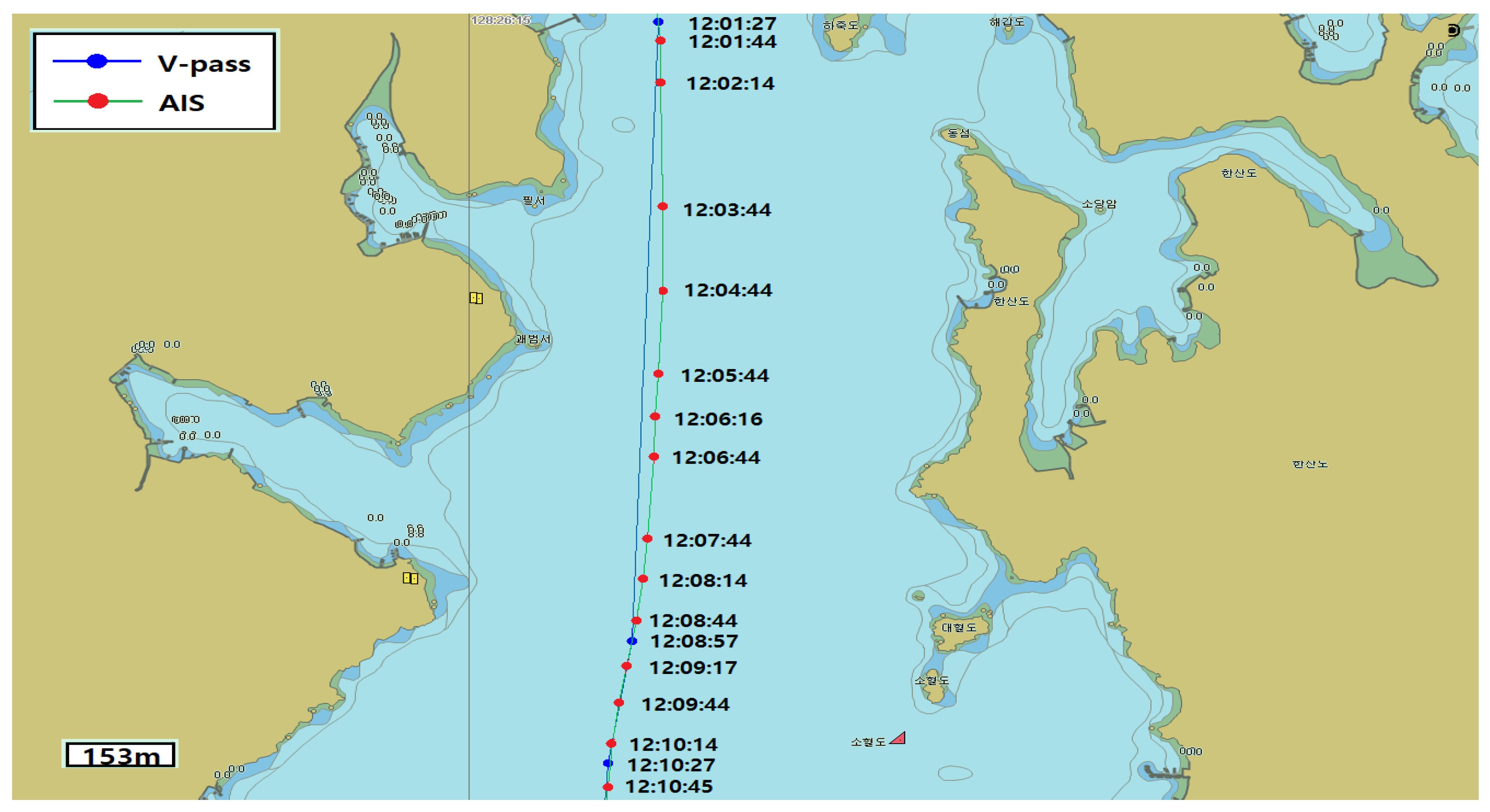
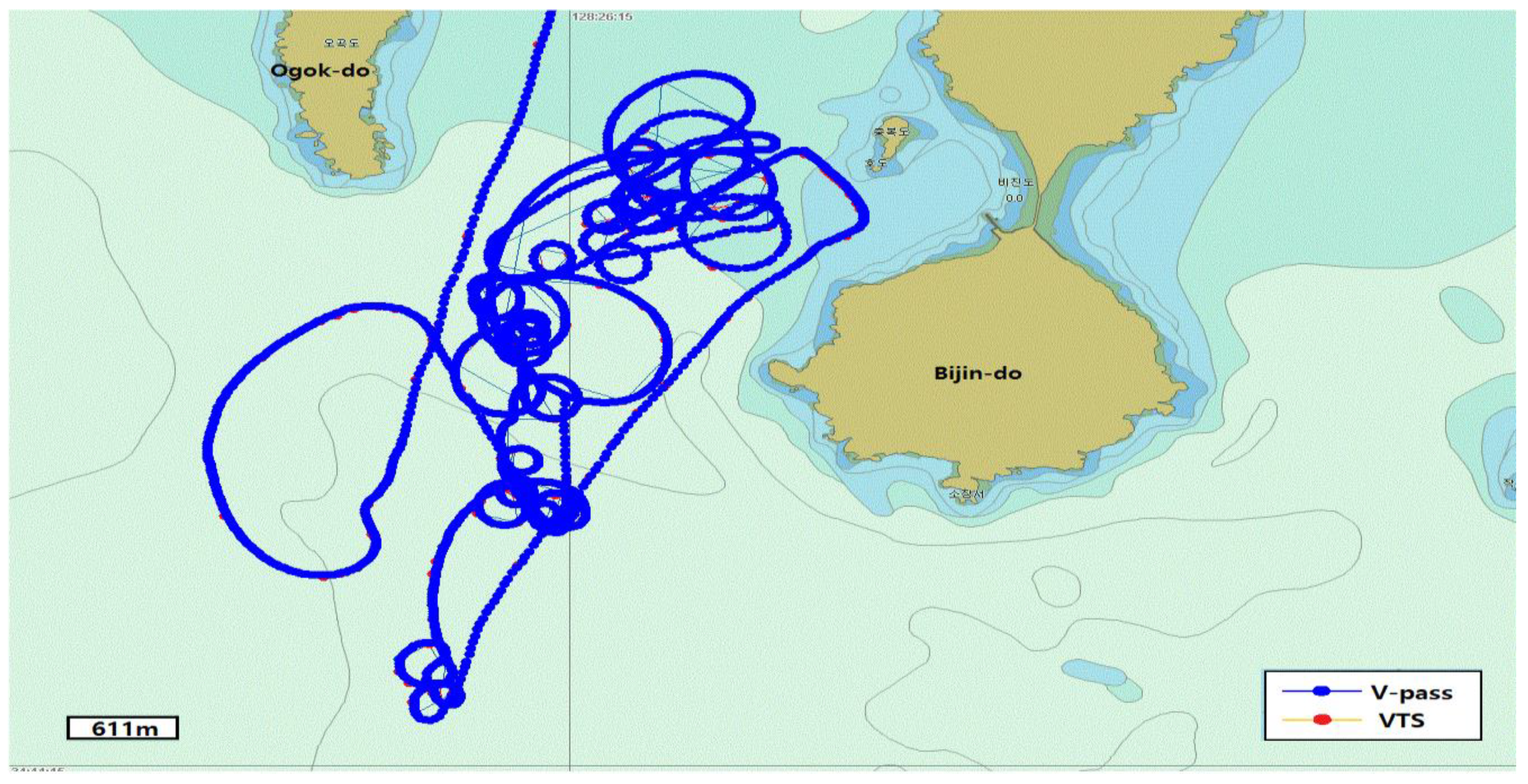
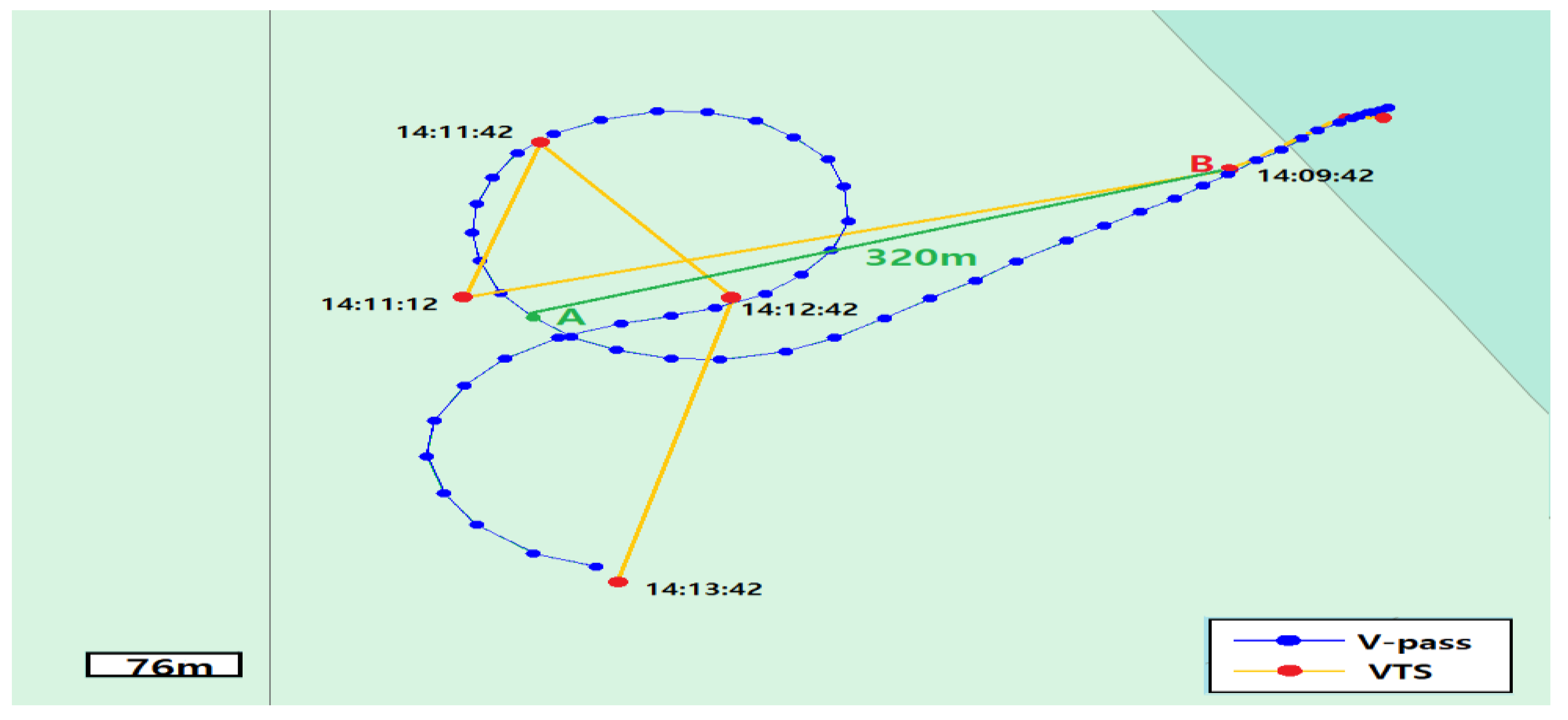
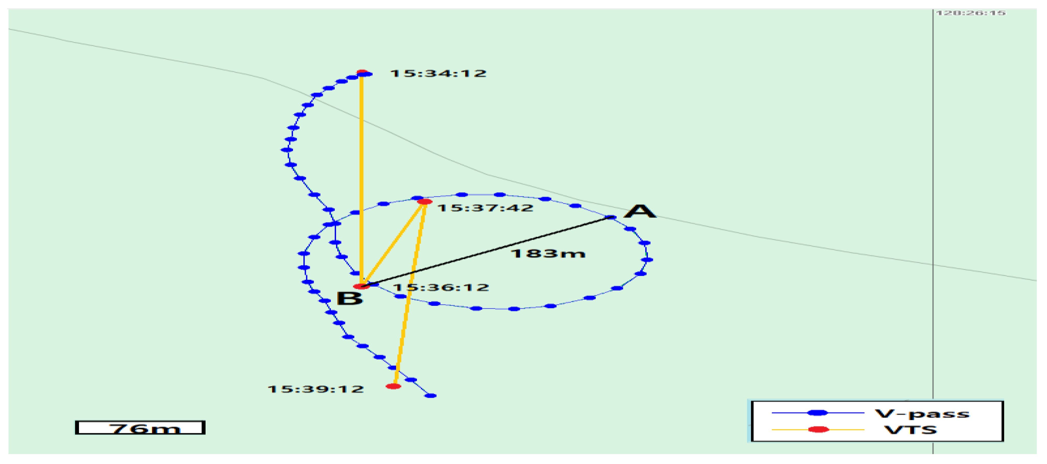
3.2. Comparison of the Data Saved in the V-Pass Terminal and the Data Received by VTS

Figure 8 is a screen-grab showing the tracking data of the ship saved every 5 s in the V-pass terminal and displayed on the electronic chart of the ship collision reproduction system. The red dots, which were transmitted by the ship every 30 s and received by VTS, are hardly visible amongst the blue dots, which were stored every 5 s. After receiving the global positioning system (GPS) signal, the difference between the data received by the VTS system and the data stored on the terminal using radio waves were comprehensively analyzed.
Figure 9 shows the Tongyoung coastal VTS radar screen, where the real-time tracking of the test ship was saved and replayed. The radar image shows the movement of the experimental ship in real time on the chart along with other nearby ships, but the stored trajectory is not as clear as that in the electronic chart of the ship collision reproduction system in Figure 8. However, it is possible to extract the trajectory of a specific ship from the stored radar image.
The blue dots and lines in Figure 10 represent the transmission data saved by the V-pass terminal in 5 s intervals, where the circular track that lasted for 4 min (14:09:42 to 14:13:42 (KST)) is represented by 47 dots. However, VTS only received five data packets during the same 4 min, which is represented with red dots and a yellow line in the figure.
Assuming that the ship was involved in an incident at approximately 14:09:42 (KST) to 14:11:12, as shown in Figure 10, VTS will send a rescue team to point B at 14:09:42 (KST), approximately 320 m from the accident point A. Although this experiment represents an extreme case, the actual situation could be more severe (as shown in Figure 3), that is, when the position of the vessel is not received by VTS for 5–7 min 30 s depending on the speed.
Similarly, the blue dots and line in Figure 11 represent the tracking data saved by the V-pass terminal in 5 s intervals. However, VTS only received four data packets within the same time period, which are marked with red dots and a yellow line. If an incident occurs at point A on the track that the fishing boat with the V-pass terminal is navigating, VTS issues a notification to the Korea Coast Guard Situation Room for point B, which is 183 m from point A, the final received location of the distressed fishing vessel, thereby triggering a nearby patrol ship.

4. Discussion

This section proposes plans to improve the problems identified from the study findings. If no other fishing boats are present in the vicinity (see Figure 10 and Figure 11), radar or other navigation equipment can be used to determine the location. However, if several fishing boats are present in the vicinity and the weather is poor, then correction cannot be determined, and the surrounding fishing boats must be directly sequentially checked. When attempting to visually identify the incident, delayed rescue operations could cause more fatalities. In particular, if the fishing boat suffers an incident and starts to sink, locating the sinking fishing boat, even with a minor positional error, will be challenging, considering that its hull will be partially visible on the water’s surface.
Blank tracking sections may occur due to various factors such as model variations and manufacturing characteristics of the V-pass and AIS terminals, terminal characteristics, antenna locations and conditions, radio shadow areas, number of ships passing in the same time zone, and communication conditions. However, the data is saved in the terminal every 30 s, and this is not an erroneous feature of the terminal but that of the process through which data is transmitted to the terminal via the antenna or that of the process through which data is received by VTS through wireless communication.
As reported in the literature [17], the AIS terminal features a built-in receiver autonomous integrity monitoring system, which verifies the accuracy and integrity of the received GPS signal. The AIS message features a built-in integrity test that runs continuously at regular intervals, significantly attenuating the integrity of the AIS or causing it to stop working. Thus, a system should be designed that activates an alarm if a failure or malfunction is detected.
Moreover, considering the published research [18,19], the AIS class-B terminals currently installed and used on fishing boats can interoperate with class-A terminals; nevertheless, it is within the range that does not overload the network used for class-A communication. AIS class-B terminals are designed to transmit and receive information only in slots that are vacant within the network, and the transmission cycle of AIS class-B terminals for ship stations is already known, assuming that it is not used for transmission when the AIS networks are heavily loaded. Therefore, the dynamic information for each AIS terminal manufacturer and tracking information cannot be stored by adjusting the update period, and the cause of an incident cannot be analyzed if there is any missing information. To address these challenges, basic requirements for dynamic-information storage should be standardized for each manufacturer. Two VHF channels (CH 87 and CH 88) are currently used to selectively receive 2250 units of information per min. Consequently, system improvements are required, such as the addition of a channel that can receive more information.
As previously mentioned, research on the positional accuracy of AIS data has been conducted [20,21,22,23,24,25,26,27,28,29]; however, most of these studies focused on only a single aspect, that is, validating the positional accuracy of the V-pass terminal. As a future research direction, further research and experimentation focusing on this aspect should be conducted under unfamiliar circumstances.

5. Conclusions

A test to validate the positional error was performed in this study by comparing the data transmitted by the V-pass terminal, which is a location transmitter installed on most fishing vessels, with the location transmitted by the AIS terminal of the ship.
The experimental V-pass and AIS tracking data packets collected for approximately 4 h showed that V-pass (269 data packets) collected 46 more data packets than AIS (223).
The Tongyoung coastal VTS, which is the V-pass land-based reception station, is located in the vicinity of the test region. The regional characteristics of Tongyoung feature several islands and radio shadow areas. For optimal transmission, 480 data packets should be received in approximately 4 h. However, only 269 V-pass data packets were received, and 211 data packets, corresponding to approximately 44% of the total transmitted data, were missing. Moreover, the AIS data was missing 237 data packets, corresponding to 54% of the total transmitted data. However, this result does not conclusively indicate that the AIS position is invariably more accurate than that of the V-pass position.
If detailed navigational data can be secured within the same time, it is possible to verify the exact hourly movement of the ship and swiftly respond in the event of a marine incident. However, there is no system to receive all the information, regardless of how regularly the ship transmits its location. This can be attributed to various reasons, such as the number of ships simultaneously operating in the same area, terminal type, radio interference, limitations of the communication system, and distance from the land relay station.
The ship location transmitter is a device that allows ships to exchange their location information; therefore, this device can prevent marine incidents such as collisions. The characteristics of the test vessel used in this study were similar to those of most fishing boats, and the location transmitter was installed using similar equipment. The scope of application of the V-pass terminals, as compared to the ship location transmitter, was limited because 91% of registered fishing boats have V-pass terminals installed and operating as fishing boat location transmitters; therefore, mutual information cannot be exchanged with automatic ship-identification devices installed on general vessels, such as merchant ships, resulting in incidents involving ship collisions. The ultimate function of the location transmission device, that is, the prevention of incidents, cannot be completely realized. Moreover, these systems face reliability issues. Therefore, such system limitations can result in incidents.
For the safe operation of fishing boats [30,31,32], which are the ultimate motivations behind installing fishing boat location-transmitting devices, the current location of the fishing boat must be determined to establish an emergency response in the event of a marine incident and to identify the exact cause of the incident. Clarifying the root cause of such incidents can prevent the reoccurrence of similar incidents. To enhance vessel and crew safety, the V-pass system must be improved through experiments and research focusing on fishing boat location transmitters.

Author Contributions

Validation, C.-H.P. and B.-K.J.; investigation, W.-S.C.; resources, C.-H.P.; data curation, B.-K.J.; writing—original draft preparation, C.-H.P.; supervision, B.-K.J. All authors have read and agreed to the published version of the manuscript.

Funding

This research received no external funding.

Conflicts of Interest

The authors declare no conflict of interest.

References

  1. National Statistical Portal. Marine Accident Statistics. Available online: https://kosis.kr (accessed on 17 April 2022).
  2. Korea Coast Guard. Statistical Yearbook of Marine Accidents; Korea Coast Guard: Incheon, Repubilc of Korea, 2022. [Google Scholar]
  3. Korea Coast Guard. Marine Accident Statistics; Korea Coast Guard: Incheon, Repubilc of Korea, 2021. [Google Scholar]
  4. Korea Information and Communication Technology Association. Wireless Data Communication Protocol V-Pass System. 2019. Available online: http://koreaict.kr/eng/ (accessed on 17 April 2022).
  5. Oh, J.H.; Kim, K.I.; Jeon, J.S.; Park, S.Y. A study on the risk analysis based on the trajectories of fishing vessel. J. Korean Inst. Navig. Port Res. 2014, 6a, 323–325. [Google Scholar]
  6. Park, J.H.; Jung, H.G.; Yang, C.S. Application of V-pass using HMM fishing boat activity prediction technique. J. Korean Soc. Coast. Disaster Prev. 2021, 8, 221–227. [Google Scholar] [CrossRef]
  7. TTAK. KO-06.0281; Wireless Data Communication Protocol for Maritime Security Safety Net. Telecommunications Technology Association: Seongnam, Republic of Korea, 2014. Available online: https://www.tta.or.kr/tta/ttaSearchView.do?key=77&rep=1&searchStandardNo=TTAK.KO-06.0281/R1&searchCate=TTAS (accessed on 17 April 2022).
  8. Choe, J.U.; Park, J.H.; Kim, H.J. A Basic Study on AIS-Based Navigation Data Analysis for Remote Situation Recognition of Autonomous Ship. J. Korean Inst. Navig. Port Res. 2020, 11a, 52–53. [Google Scholar]
  9. Jung, C.H.; Choi, W.K.; Park, S.H. A Study on the Improvement of AIS Equipmentthrough the Users Survey. J. Korean Marit. Police 2016, 6, 117–132. [Google Scholar]
  10. TTAK. KO-06.0281; Wireless Data Communication Protocol for V-Pass System. Telecommunications Technology Association: Seongnam, Republic of Korea, 2019. Available online: https://www.tta.or.kr/tta/ttaSearchView.do?key=77&rep=1&searchStandardNo=TTAK.KO-06.0281/R1&searchCate=TTAS (accessed on 17 April 2022).
  11. Han, H.R. A SpatioTemporal Variation Pattern Analysis of Fishing Activity in the Jeju Sea of Korea Using V-Pass Data. Ph.D. Thesis, Department of Spatial Information Engineering, The Graduate School Pukyong National University, Busan, Republic of Korea, 2021. [Google Scholar]
  12. Han, J.R.; Kim, T.H.; Choi, E.Y.; Choi, H.W. A study on the mapping of fishing activity using V-pass data—Focusing on the Southeast Sea of Korea. J. Korea Geogr. Inf. Soc. 2021, 24, 112–125. [Google Scholar]
  13. Kim, K.U.; Lee, W.J. A study on the advanced schemes on the welfare accommodation of fishing crew. J. Korea Ship Saf. Technol. Auth. 2012, 34, 2–17. [Google Scholar]
  14. Park, C.H.; Jung, B.K.; Lee, N.W. A study on the application of the navigation analysis system for the proof of ship crimes. Korean Assoc. Marit. Police Sci. 2022, 12, 85–104. [Google Scholar] [CrossRef]
  15. Korea Research Institute of Ships & Ocean Engineering. Development of Replay System of Ships’ Collision Accident; Research Service Report; Korea Research Institute of Ships & Ocean Engineering: Daejeon, Republic of Korea, 2014; Available online: https://www.kriso.re.kr/ (accessed on 17 April 2022).
  16. Ship Marine Plant Laboratory. Development of Marine Specialized Ship Collision Reproduction System; Research Service Report; Ship Marine Plant Laboratory: Daejeon, Republic of Korea, 2014; Available online: https://www.kriso.re.kr/ (accessed on 17 April 2022).
  17. Kim, J.W.; Jeong, M. Basic Study on Improving the Reliability of AIS data: Focused on Vessel Traffic Service Operators. J. Korea Marit. Police Assoc. 2021, 11, 49–68. [Google Scholar]
  18. An, J.O. A Study on the Utilization of Marine Safety Radio Facilities and the Efficiency of Frequency Utilization; Final Research Report; National Radio Research Institute: Naju-si, Republic of Korea, 2013; Available online: https://www.rra.go.kr/ (accessed on 17 April 2022).
  19. TTAK. KO-06.0281; Radio Data Communication Protocol Maritime Security Network. Telecommunications Technology Association: Seongnam, Republic of Korea, 2016. Available online: https://www.tta.or.kr/tta/ttaSearchView.do?key=77&rep=1&searchStandardNo=TTAK.KO-06.0281/R2&searchCate=TTAS (accessed on 17 April 2022).
  20. Kim, B.O. Message error probability analysis by AIS slot interference. In Proceedings of the Autumn Academic Conference of the Korean Society of Navigation and Harbour. J.Korean Institute Navig. Port Res. 2010, 10a, 164–166. [Google Scholar]
  21. Kim, D.Y.; Hong, T.H.; Jeong, J.S.; Lee, S.J. Building an algorithm for compensating AIS error data. J. Korean Inst. Intell. Syst. 2014, 24, 181–203. [Google Scholar]
  22. Jeong, J.S.; Yang, W.J. A study on the enhancement of utilization of automatic identification system. J. Korean. Soc. Mar. Environ. Saf. 2003, 9, 15–21. [Google Scholar]
  23. Kim, D.W.; Ha, M.J. A Study on the Collection and Utilization of Collected Information through V-pass System, Focusing on Infringement of Fundamental Rights and Legislative Solution. J. Korean Assoc. Marit. Police Sci. 2021, 9, 310–315. [Google Scholar] [CrossRef]
  24. Kim, K.I.; Jung, J.S.; Park, G.G. A Study on the Estimation of Center of Turning Circle of Anchoring Vessel using Automatic Identification System Data in VTS. J. Navig. Port Res. 2013, 8, 337–343. [Google Scholar] [CrossRef]
  25. Seo, K.Y.; Hong, T.H.; Park, G.G.; Choi, C.S. Analysis of Operational State and Radio Environmont of AIS. J. Korean Soc. Marit. Inf. Commun. 2005, 9, 177–180. [Google Scholar]
  26. Chao, C. A Study on Development of Expert System for Collision Avoidance and Navigation Based on AIS. Ph.D. Thesis, Department of Ship Operation Systems Engineering Graduate School of Korea Maritime and Ocean University, Busan, Republic of Korea, 2009. [Google Scholar]
  27. Last, P.; Bahlke, C.; Hering-Bertram, M.; Linsen, L. Comprehensive analysis of Automatic Identification System (AIS) data in regard to vessel movement prediction. J. Navig. 2014, 67, 791–809. [Google Scholar] [CrossRef]
  28. Lee, S.J.; Jeong, J.S.; Kim, M.Y.; Park, G.K. A study on real-time message analysis for AIS VDL load management. J. Korean Inst. Intell. Syst. 2013, 23, 236–261. [Google Scholar]
  29. Hu, Q.; Jiang, Y.; Zhang, J.; Sun, X.; Zhang, S. Development of an automatic identification system autonomous positioning system. Sensors 2015, 15, 28574–28591. [Google Scholar] [CrossRef] [PubMed]
  30. Wang, H.; Liu, Z.; Wang, H.; Graham, T.; Wang, J. An analysis of factors affecting the severity of marine accidents. Reliab. Eng. Syst. Saf. 2021, 210, 07513. [Google Scholar] [CrossRef]
  31. Wang, X.; Xia, G.; Zhao, J.; Yang, Z.; Loughney, S.; Fang, S.; Zhang, S.; Xing, Y.; Liu, Z. A novel method for the risk assessment of human evacuation from cruise ships in maritime transportation. Reliab. Eng. Syst. Saf. 2023, 230, 108887. [Google Scholar] [CrossRef]
  32. Fang, S.; Liu, Z.; Wang, X.; Wang, J.; Yang, Z. Simulation of evacuation in an inclined passenger vessel based on an improved social force model. Saf. Sci. 2022, 148, 105675. [Google Scholar] [CrossRef]
Figure 1. Automatic Identification System (AIS) and V-pass antennas installed at the same place on the ship.
Jmse 11 01023 g001
Figure 2. Sea trial location (between Bijin-do and Ogok-do).
Jmse 11 01023 g002
Figure 3. Comparison of the AIS and V-pass data.
Jmse 11 01023 g003
Figure 4. Linear route trajectory section where more AIS data was saved than V-pass data.
Jmse 11 01023 g004
Figure 5. Sections where more AIS data was transmitted than V-pass data in a non-linear track.
Jmse 11 01023 g005
Figure 6. Linear route where more V-pass data was saved than AIS data.
Jmse 11 01023 g006
Figure 7. Curved sections where more V-pass data was saved than AIS data.
Jmse 11 01023 g007
Figure 8. V-pass data rendered on the electronic chart of the ship collision reproduction system.
Jmse 11 01023 g008
Figure 9. Screen-grab of the Tongyong coastal Vessel Traffic Service (VTS) radar screen showing the experimental track.
Jmse 11 01023 g009
Figure 10. Comparison of the V-pass data and the five data packets received by VTS.
Jmse 11 01023 g010
Figure 11. Comparison of the stored V-pass data and the four data packets received by VTS.
Jmse 11 01023 g011
Table 1. AIS class A nominal reporting interval (ITU-R M.1371-4).
Dynamic Condition of the ShipNominal Reporting Interval
Ship at anchor or moored and not moving faster than 3 knots3 min
Ship at anchor or moored and moving faster than 3 knots10 s
Ship moving at 0–14 knots10 s
Ship moving at 0–14 knots and changing course3.3 s
Ship moving at 14–23 knots6 s
Ship moving at 14–23 knots and changing course2 s
Ship moving at >23 knots2 s
Ship moving at >23 knots and changing course2 s
Table 2. AIS class B nominal reporting interval (ITU-R M.1371-4).
Dynamic Condition of the ShipNominal Reporting Interval
Ship not moving faster than 2 knots3 min
Ship moving at 2–14 knots30 s
Ship moving at 14–23 knots15 s
Ship moving at >23 knots5 s
Disclaimer/Publisher’s Note: The statements, opinions and data contained in all publications are solely those of the individual author(s) and contributor(s) and not of MDPI and/or the editor(s). MDPI and/or the editor(s) disclaim responsibility for any injury to people or property resulting from any ideas, methods, instructions or products referred to in the content.

