Article

An Analytical Dynamic Model for Vibration Suppression of a Multi-Span Continuous Bridge by Tuned Mass Dampers

1
School of Electromechanical and Automotive Engineering, Yantai University, Yantai 264005, China
2
State Key Laboratory of Mechanics and Control of Mechanical Structures, Nanjing University of Aeronautics and Astronautics, Nanjing 210016, China
3
Yantai Marine Economic Research Institute, Yantai 264000, China
*
Authors to whom correspondence should be addressed.
J. Mar. Sci. Eng. 2023, 11(5), 1017; https://doi.org/10.3390/jmse11051017
Submission received: 5 April 2023 / Revised: 4 May 2023 / Accepted: 8 May 2023 / Published: 10 May 2023
(This article belongs to the Special Issue Advances in Marine Structures)

Abstract

:
In this paper, an analytical dynamic model is proposed for vibration suppression of a multi-span continuous bridge by tuned mass dampers (TMDs). Firstly, the partial differential equations (PDEs) that govern the motion of the multi-span continuous bridge and the TMDs are obtained, respectively. According to the matching conditions and the boundary conditions, the mode shapes of the multi-span continuous bridge are derived, and the orthogonality relations of the mode shapes are proven. By using the mode shapes and their orthogonality relations, the PDEs that govern the motion of the bridge and the TMDs are truncated into the ordinary differential equations (ODEs) that describe the motion of the entire system. To verify the proposed model, the natural frequencies solved by the frequency equation are compared with those obtained by the finite element software ANSYS. According to the ODEs in this model, the dynamical responses of the system are worked out to study the influence of the location and the number of TMDs on the vibration suppression of the bridge.

1. Introduction

With the rapid development of sea-crossing bridges, a multi-span continuous bridge has been broadly used in the fields of civil engineering and transportation engineering. Due to the action of complicated environmental loads, the bridge may produce excessive vibration, reducing the stability and fatigue strength of the bridge. In this regard, it is often used to install TMDs to suppress excessive vibration of the bridge. The precision of the dynamic model, however, has a significant impact on the TMDs’ capacity to reduce vibration. In order to better use TMDs for vibration control of the multi-span continuous bridge, the first step is to create an accurate dynamic model.
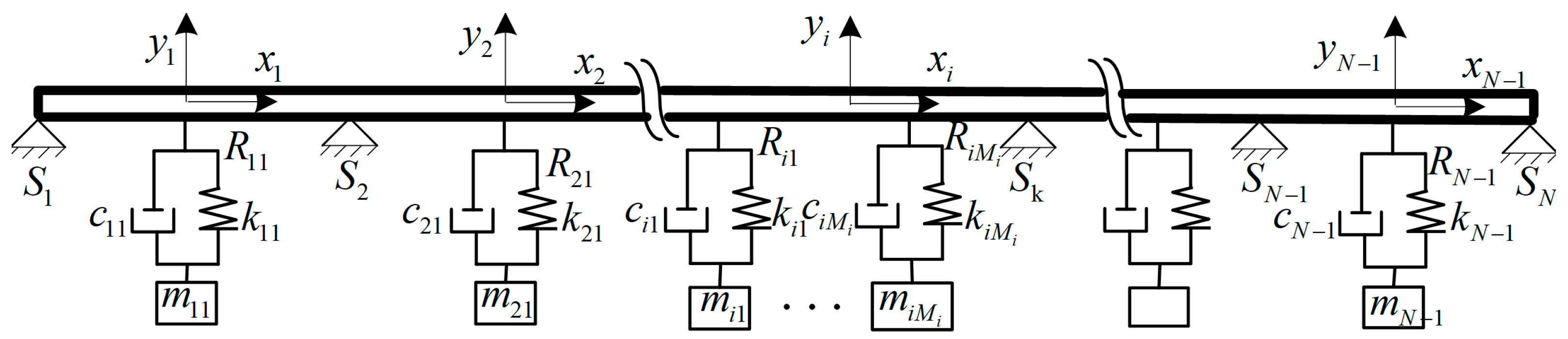
For the bridge system with TMDs, it is usually separated into the beam bridge and the TMDs subsystem in the process of dynamic modeling, and then the dynamic model of the scheme is constructed by coupling the interaction forces of these two subsystems. The partial differential equation controls the continuous scheme with infinite degrees of freedom (DOFs), known as the beam. To facilitate dynamic analysis and control, it needs to be converted to a discrete system with finite DOFs, described by the ordinary differential equation.
For a single-span bridge system with TMDs, because of the simple structure of the single-span bridge, the trigonometric function can be directly selected as its mode function to obtain the dynamic model with low dimension and high accuracy. As a result, this model is frequently used to analyze how the TMDs on the bridge reduce vibration under different loads, such as moving load [1,2,3,4,5,6,7] and wind load [8,9,10,11,12,13]. Wang et al. [1] analyzed the suppression impact of the TMD on bridge vibration caused by the train, and the findings indicate that the TMD has a good vibration suppression effect when the train is at resonance speed. Then, they analyzed the vibration suppression effect of multiple TMDs on the bridge under the resonant speed of the train [4]. The reduction of self-excited vibration between a vehicle and a bridge using the TMD was investigated by Zhou [6]. Andersen et al. [10] studied how the TMD affected the resonance of bridges caused by the vortex. Xu et al. [9] proposed a TMD with an inert device, which can better suppress the vortex-induced resonance response of the bridge. Domaneschi and Martinelli found that the energy dissipation device in passive TMDs can also perform better in wind buffering vibration [14]. In addition, many other scholars have proposed various types of TMDs [15,16], such as Pellizzari et al., who studied the optimal performance design criteria of MTMD based on structural uncertainty [17], which have been applied to single-span bridges to demonstrate their better vibration suppression effects compared to traditional TMDs [18,19].
For the multi-span continuous bridge system with TMDs, because of its complex structure, the mode function with analytical expression cannot be directly obtained as for the single-span bridge. The FEM is used to first determine the mode displacements of each node of the structure, and the mode functions of the bridge are fitted by the interpolation method [20,21]. The interaction between the bridge and the TMD is then used to build the dynamic model of the multi-span bridge. Based on this, many scholars have researched the vibration suppression effect of the TMD on multi-span bridges under vortex excitation [22,23] and seismic excitation [24,25], and the TMD optimization design for vibration control of multi-span bridges. Crespi et al., based on the FEM, evaluated the safety and durability of the structure based on a variety of reinforced concrete multi-span bridges [26,27].
Although the FEM and the interpolation method may be used to generate the mode functions of the multi-span continuous bridge, the process of obtaining the mode functions has the problems of a heavy workload and being time-consuming, which brings great inconvenience to the establishment of the dynamic model and the dynamic analysis based on the model. In contrast, using the analytical method to obtain the mode functions of the multi-span continuous bridges can not only ensure its accuracy but also greatly reduce the workload. In this regard, Ichikawa et al. [28] obtained the mode functions of multi-span bridges by combining the eigenfunction expansion method with the direct integration method. The coefficient matrix of the vibration scheme eigenfunction was established by Lin and Tsai [29] using the numerical assembly approach for the traditional FEM. The multi-span beam with spring-mass systems’ natural frequencies and mode functions may be found by solving the matrix. However, obtaining the modal function of a multi-span bridge by the analytical method mentioned above is still quite tedious, which brings difficulties to the dynamic modeling of the multi-span continuous bridge with TMDs. In recent years, Wei and Cao proposed a methodology suitable for obtaining the mode functions of complex flexible structures. The process of obtaining the mode functions is simple and straightforward, and has been utilized to model the dynamic behavior of flexible space manipulators [30], multi-beam jointed structures [31,32], and flexible spacecraft with jointed solar wings [33,34]. Based on this methodology, the presented work is devoted to obtaining the mode functions in analytical form for the purpose of establishing the analytical dynamic model of the multi-span bridge with TMDs.
In this research, the explicit orthogonality relations for mode forms of the multi-span beam are described. Mode shapes of the multi-span bridge were derived using the approach suggested in [30,32,34]. By applying the mode functions of the multi-span bridge and their orthogonal relations, the analytical dynamic model of the entire system is generated through the interaction force coupling between the multi-span continuous beam and the TMDs. To show the validity of the suggested model, the natural frequencies produced by the proposed model are compared with those obtained by the finite element software ANSYS. The dynamic responses of the system under the vortex-induced force are presented, based on the dynamic equations in the suggested model, to evaluate the suppressing impact of TMDs on the vibration response of the multi-span bridge.

2. Dynamic Modeling of the Bridge System

2.1. Bridge System

As shown in Figure 1, the continuous bridge is divided into N 1 spans by the simple supports, S k ( k = 1 , 2 , N ) , and the i-th span of the bridge carries a number N i of viscoelastic TMDs. R i j is the attaching point of the j-th TMD on the i-th span of the bridge. Each span of the continuous bridge is assumed to have an equal cross-sectional area and uniform material properties. The relevant physical parameters of the bridge are as follows: E is the modulus of elasticity, I is the moment of inertia of the bridge, ρ is the mass per unit length, and L i is the length of the i-th span of the bridge. Let ( x i , y i ) be the local coordinate of the i-th span of the bridge in the vertical plane, with the origin situated in the middle of the i-th span of the bridge.
According to the Euler–Bernoulli beam theory, the equation of motion for the i-th span of the bridge can be expressed as:
E I w i + ρ w ¨ i + ξ w ˙ i + η I w ˙ i = p i ( x , t ) + f i ( x , t ) ,   i = 1 , 2 , , N 1
where partial differentiation with respect to time t is indicated by an over-dot, and partial differentiation with respect to x is shown by a prime. w i is the vertical displacement of the i-th span of the bridge, p i ( x , t ) is the force acting on the i-th span of the bridge by the TMDs, f i ( x , t ) is the distributed external force on the i-th span of the bridge, and ξ and η are the external and internal damping coefficients of the bridge.
Corresponding to the TMD subsystem, the j-th force can be demonstrated as:
p i ( x , t ) = j = 1 N i δ ( x R i j ) [ c i j ( z ˙ i j w ˙ i ( L i 2 + R i j , t ) ) + k i j ( z i j w i ( L i 2 + R i j , t ) ) ]
where R i j is the position of the j-th TMD on the i-th span of the bridge. c i j and k i j are the damping coefficient and spring stiffness of the j-th TMD on the i-th span of the bridge, respectively, z i j is the vertical displacement of the j-th TMD on the i-th span of the bridge relative to the static equilibrium position, and w i ( l i 2 + a i j , t ) is the vertical displacement of the i-th bridge’s span at the attaching point, R i j .
The equation of motion is as follows for the j-th TMD on the i-th span of the bridge:
m i j z ¨ i j + c i j ( z ˙ i j w ˙ i ( L i 2 + R i j , t ) ) + k i j ( z i j w i ( L i 2 + R i j , t ) ) = 0 ,   j = 1 , 2 , N i .

2.2. Determination of Mode Shapes of the Continuous Bridge

First, the continuous bridge’s boundary value problem has to be examined, which includes the continuous conditions at the simple supports, S k ( k = 2 , 3 , N 1 ) , and the boundary conditions at the ends S 1 and S N . The continuous conditions at the simple supports, S k ( k = 2 , 3 , N 1 ) , are:
w k 1 ( L k 1 2 , t ) = w k ( L k 2 , t ) = 0
w k 1 ( L k 1 2 , t ) = w k ( L k 2 , t )
E I w k 1 ( L k 1 2 , t ) = E I w k ( L k 2 , t )
The boundary conditions at the ends S 1 and S N are:
w 1 ( L 1 2 , t ) = 0 ,   E I w 1 ( L 1 2 , t ) = 0
w N 1 ( L N 1 2 , t ) = 0 ,   E I w N 1 ( L N 1 2 , t ) = 0
To obtain the mode shapes of the continuous bridge, the system eigenvalue problem must be solved. The displacements of the continuous bridge are assumed to be separable in space and time, and they are expressed as:
w i ( x , t ) = φ i ( x ) e j ω t ,   i = 1 , 2 , , N 1
where ω is an unidentified constant that corresponds to the continuous bridge’s natural frequency. By using the separable solution given in Equation (9), and the equations of the motion for the i-th span of the bridge in Equation (1) without the damping, the force of the TMDs and the distributed external force are transformed into the following form:
E I φ i ( x ) ω 2 ρ φ i ( x ) = 0 ,   i = 1 , 2 , , N 1
The solution of Equation (10) is demonstrated as:
φ i ( x ) = A i cos ( β x ) + B i sin ( β x ) + C i cosh ( β x ) + D i sinh ( β x ) ,   x [ L i 2 , L i 2 ]
where β = ( ρ ω 2 E I ) 1 / 4 . Let:
ψ i = [ A i B i C i D i ] ,   ψ = [ ψ 1 ψ 2 ψ N 1 ] T
The characteristic equation can be obtained by adding Equation (11) into Equations (4)–(8), as:
H ( ω ) ψ = 0
where H ( ω ) R ( 4 N 4 ) × ( 4 N 4 ) .
For the coefficient vector ψ to be nonzero, the determinant of the matrix H ( ω ) must be zero, namely:
det [ H ( ω ) ] = 0
The solutions of Equation (14) represent the natural frequencies of the continuous bridge. Once the s-th natural frequency, ω bs , of the continuous bridge is solved by Equation (14), the coefficient vector ψ ( s ) can be determined by Equation (13). Using Equation (11) then yields the s-th mode shape for the continuous bridge.

2.3. Orthogonality of the Mode Shapes of the Continuous Bridge

The two different eigenvalues, ω b r and ω b s , are represented by the mode shapes ϕ r ( x ) and ϕ s ( x ) .
ϕ r ( x ) = [ φ 1 r φ 2 r φ N 1 r ] T ,   r = 1 , 2 ,
Substituting the separable solutions given in Equation (15) into Equation (1) without damping yields:
E I φ i r ( x ) = ω b r 2 ρ φ i r ( x ) ,   i = 1 , 2 , , N 1 .
Multiplying Equation (16) by φ i s ( x ) , integrate the resulting equations from x = L i / 2 to x = L i / 2 for the i-th span of the bridge and the sum of the resulting equations to obtain:
i = 1 N 1 L i 2 L i 2 E I φ i r ( x ) φ i s ( x ) d x = ω b r 2 i = 1 N 1 L i 2 L i 2 ρ φ i r ( x ) φ i s ( x ) d x .
Using the integration part in Equation (17) and employing the boundary and matching conditions in Equations (4)–(8) results in:
i = 1 N 1 L i 2 L i 2 E I φ i r ( x ) φ i s ( x ) d x = i = 1 N 1 L i 2 L i 2 E I φ i r ( x ) φ i s ( x ) d x .
From Equations (17) and (18), we get:
i = 1 N 1 L i 2 L i 2 E I φ i r ( x ) φ i s ( x ) d x = ω b r 2 i = 1 N 1 L i 2 L i 2 ρ φ i r ( x ) φ i s ( x ) d x .
By using Equation (19), exchanging the superscripts s and r results in:
i = 1 N 1 L i 2 L i 2 E I φ i r ( x ) φ i s ( x ) d x = ω b s 2 i = 1 N 1 L i 2 L i 2 ρ φ i r ( x ) φ i s ( x ) d x .
Equation (19) minus Equation (20) gives:
( ω b r 2 ω b s 2 ) i = 1 N 1 L i 2 L i 2 ρ φ i r ( x ) φ i s ( x ) d x .
The first orthogonality relation can be found in Equation (21) as:
i = 1 N 1 L i 2 L i 2 ρ φ i r ( x ) φ i s ( x ) d x = M s δ r s .
where M s represents the s - th modal mass of the continuous bridge, and δ r s is the Kronecker delta. The second orthogonality relation can be established by using Equations (19) and (22) as:
i = 1 N 1 L i 2 L i 2 E I φ i r ( x ) φ i s ( x ) d x = K s δ r s .
where K s represents the s-th modal stiffness of the continuous bridge.

3. Dynamic Model

By using the characteristic Equation (13) and the frequency Equation (14), the mode shapes of the continuous bridge can be determined. Then, the displacements of the bridge can be expressed as a series of spatial mode shapes multiplied by time-dependent modal coordinates, as:
w i ( x , t ) = r = 1 n ϕ i r ( x ) q r ( t ) .
where ϕ i r ( x ) is the r-th mode shape of the i-th span of the bridge, and q r ( t ) is the r-th modal coordinate.
Introducing Equation (24) into the equation of motion of the bridge in (1) leads to:
r = 1 m E I ϕ i r ( x ) q b r + r = 1 m ρ ϕ i r ( x ) q ¨ b r + r = 1 m ξ ϕ i r ( x ) q ˙ b r + r = 1 m η I ϕ i r ( x ) q ˙ b r p i ( x , t ) = f i ( x , t ) ,             i = 1 , 2 , , N 1 .
Multiplying Equation (25) by ϕ i s ( x ) , integrate the resulting equations from x = L i / 2 to x = L i / 2 for the i-th span of the bridge. Using the orthogonality relations in Equations (22) and (23) and arranging all the derived equations, we have:
M s q ¨ s ( t ) + C s q ˙ s ( t ) + K s q s ( t ) P s ( x , t ) = F s ( x , t ) ,   s = 1 , 2 , , n .
Combining Equations (3) and (26), we get:
M Y ¨ + C Y ˙ + K Y = F .
where M , C and K are ( n + i = 1 N 1 N i ) × ( n + i = 1 N 1 N i ) matrices, and Y and F are ( n + i = 1 N 1 N i ) × 1 vectors, and they are expressed as:
Y = [ q Z ] T ,   F = [ F 1 ( t ) F 2 ( t ) F n ( t ) 0 1 × i = 1 N 1 N i ] T , q = [ q 1 q 2 q n ] ,   Z = [ Z 1 Z 2 Z N 1 ] , Z i = [ z i 1 z i 2 z i N i ] ,   i = 1 , 2 , , N 1 , M = [ M b P 0 i = 1 N 1 N i × n m ] ,   C = [ C b 0 n × i = 1 N 1 N i C T c ] ,   K = [ K b 0 n × i = 1 N 1 N i K T k ] .
The other parameters in Equation (28) are presented in Appendix A.
By omitting the damping and external loads from Equation (27), the equations of motion of the system with multi-degrees-of-freedom are stated as:
M Y ¨ + K Y = 0 .
The solution of Equation (29) is written in the following form:
Y ( t ) = ϕ sin ( ω t + θ ) .
Equation (30) is substituted into Equation (29), resulting in:
[ K ω 2 M ] ϕ = 0 .
A nontrivial solution is possible only when:
det [ K ω 2 M ] = 0 .
The roots of Equation (32) represent the natural frequencies of the system, which are denoted in ascending order by ω 1 , ω 2 , . Once the r-th natural frequency, ω r , of the bridge system is solved by Equation (32), the corresponding vector, ϕ r , can be determined by Equation (31).

4. Results and Discussion

Based on the dynamic model in this paper, the natural frequencies and mode shapes of the system were obtained, which were then compared with those obtained from the finite element software ANSYS. Then, the dynamic responses of the bridge for different cases are given to study the vibration suppression effect of TMDs on the bridge.

4.1. Model Validation

The bridge system is a uniform three-span continuous beam with three spring-mass subsystems, as shown in Figure 2. The length of each span of the beam is L 1 = 0.3   m ,   L 2 = 0.4   m ,   L 3 = 0 . 3   m , and the position of the spring-mass subsystem is a 11 = a 21 = a 31 = 0.1   m . The relevant physical parameters of the bridge system are shown in Table 1. By solving the frequency Equation (32), the natural frequency of the bridge system can be obtained, and these results were compared with those obtained from the finite element software ANSYS, as shown in Table 2. For the finite element model, the beam, the spring, and the mass are modeled by the BEAM element, the SPRING element (body-body), and the MASS element, respectively. Each beam is divided into 400 elements. The first four mode shapes of the system were obtained by the characteristic Equation (31), as shown in Figure 3, where the positions of the spring-mass subsystems are represented by .
Table 2 shows that the results obtained from the proposed model were in excellent agreement with those obtained from ANSYS, where the largest difference in natural frequencies was only 0.26 % . In addition, the first four mode shapes obtained by the proposed model were exactly the same as those from the model in ANSYS, as shown in Figure 3. All the above findings prove the validity of the dynamic model proposed here.

4.2. Vibration Responses

Vortex-induced vibration is one of the most common wind-induced vibrations in bridges at low wind speeds. The vortex-induced vibration responses of the multi-span continuous bridge with TMDs were estimated by the presented model, in comparison to those of the multi-span continuous bridge without TMDs. Assuming that the vortex-induced force is a harmonic force model [35], its expression is:
f ( t ) = F v sin ( Ω t + θ )
where F v is the amplitude of the vortex force related to factors such as air density, wind speed, and structural size, and Ω is the frequency of vortex shedding.
Based on Den Hartog’s principle [36], the frequency, f T , and damping ratio, ξ T , of the TMD are selected as f T = f b / ( 1 + μ ) and ξ T = 3 μ / 8 ( 1 + μ ) , respectively, where f b is the natural frequency of the bridge, and μ is the mass ratio of the TMD to the mass of the span where the TMD is located, which is defined as:
μ = m i j ρ L i ,   i = 1 , 2 , , N 1 ,   j = 1 , 2 , N i .
In this section, the relevant physical parameters of the bridge system were selected as ρ = 155590   kg / m 3 ,   E = 2.1 × 10 11   Pa , and I = 29.87   m 4 .

4.2.1. Three-Span Continuous Bridge

For the first case, the length of each span of the bridge was selected as L 1 = L 2 = L 3 = 110   m . Then, the first four natural frequencies of the bridge were ω 1 = 0.82   Hz , ω 2 = 1.06   Hz , ω 3 = 1.54   Hz , and ω 4 = 3.30   Hz , and the damping ratios of the bridge were c b 1 = 1.1 % ,   c b 2 = 1.0 % ,   c b 3 = 0.9 % ,   c b 4 = 1.4 % . The first four mode shapes of the bridge without TMDs are shown in Figure 4. As can be seen from this figure, due to the symmetry of the bridge, the first and third mode shapes were symmetrical and the second and fourth mode shapes were anti-symmetrical. When the symmetric bridge was subjected to a uniformly distributed harmonic vortex-excited force, the anti-symmetric mode could not be excited. Therefore, the resonant responses on the first and the third modes were calculated to study the vibration suppression effect of TMDs, respectively. From Figure 4, it can be seen that the midpoint of each span of the bridge had a large deformation in the first and the third modes. Thus, the midpoint of each span of the bridge is regarded as the attachment position of the TMD, which is represented by Roman numerals.
In the resonant response of the first and third modes, the frequency–response curves of the three-span bridge with different cases for μ = 0.2 % and μ = 0.5 % were as shown in Figure 5 and Figure 6, respectively. In these figures, w ^ i is the displacement of the midpoint of the i-th span of the bridge. For the different cases, the Arabic numerals and Roman numerals represent the number and attachment position of TMDs, respectively, as shown in Table 3 and Table 4 and Figure 5 and Figure 6.
In order to investigate the vibration suppression effect of the TMDs, the vibration suppression effect, R i , of the i - th span of the bridge is defined as:
R i = w A i w B i w A i × 100 %
where w B i and w A i represent the displacement at the midpoint of the i - th span of the bridge with and without TMDs, respectively.
From Figure 5 and Table 3, it can clearly be seen that the increase of the mass of the TMD can improve the vibration suppression effect of the bridge but can also increase the difference in resonance frequency between the bridge with and without TMDs. In the cases of μ = 0.2 % and μ = 0.5 % , the installation of the TMD at the midpoint of any span of the bridge not only has an obvious vibration suppression effect on the span of the bridge where the TMD is installed, but also has a good vibration suppression effect on the other spans of the bridge. For example, by installing a TMD with a mass ratio of   0.2 % only at the midpoint of the first span, the amplitude at the midpoint of each span of the bridge can be reduced by at least more than 48 % . In addition, it is worth noting that the increase of the number of TMDs does not significantly enhance the vibration suppression effect, but it significantly increases the difference in resonance frequency between the bridges with and without TMDs.
From Figure 6 and Table 4, it is clear that the increase of the TMD mass can enhance the vibration suppression effect of the bridge and increase the difference in resonance frequency between the bridges with and without TMDs, which is the same as observed in the resonance response of the first mode. When the TMD mass ratio is   0.5 % , installing the TMD on the second span of the bridge can not only achieve a good vibration suppression effect (about 70 % ) on the second span of the bridge, but can also have a good vibration suppression effect on other spans of the bridge (about 70 % ). However, this can significantly change the resonant frequency of the whole bridge. When the TMD is installed on the first or third span of the bridge, compared with the second span of the bridge, the vibration suppression effect of the whole bridge can be reduced. At the same time, the difference in resonance frequency between the bridges with and without TMDs can be significantly reduced.
Based on the above analysis, the frequency–response curves of the three-span bridge for different cases are provided to study the vibration suppression effect of the TMD on the bridge in the resonant response of the first and third modes, as shown in Figure 7. In this figure, the mass ratio of the TMDs was   0.5 % and they were installed at the center of each span. Point A indicates that the TMDs for the first mode are installed at the first and third spans of the bridge, and the TMD for the third mode is installed at the second span of the bridge. Similarly, point B indicates that the TMD for the first mode is installed at the first span of the bridge, and the TMD for the third mode is installed at the second span of the bridge. Point C indicates that the TMD for the first mode is installed at the second span of the bridge, and the TMDs for the third mode are installed at the first and third spans of the bridge.
From Figure 7, it can be seen that the TMDs installed for the resonance response of the first and third modes have the same vibration suppression effect in the resonance response of the first mode as the TMD installed for the resonance response of the first mode only. This indicates that the vibration suppression effects of TMDs for resonance responses of different modes are not coupled with each other. For the vibration suppression effect of the TMD, the vibration suppression effect under the case of A was the best, followed by the case of B and the case of C, and the difference in the vibration suppression effect was small. For the effect of TMD on resonance frequency, the case of A had the largest effect on resonance frequency, and the smallest was for case C. These results can also be observed in Table 3 andTable 4 and Figure 5 and Figure 6.

4.2.2. Four-Span Continuous Bridge

For the second case, the length of each span of the bridge was L 1 = L 2 = L 3 = L 4 = 110   m . The first four natural frequencies of the bridge were ω 1 = 0.82   Hz ,   ω 2 = 0.96   Hz ,   ω 3 = 1.29   Hz ,   ω 4 = 1.66   Hz , and the damping ratios of the bridge were c b 1 = 1.1 % ,   c b 2 = 1.0 % ,   c b 3 = 1.0 % ,   c b 4 = 1.0 % . The first four mode shapes of the bridge without TMDs are depicted in Figure 8. It is clear from this figure that the first and third mode shapes were anti-symmetrical and the second and fourth mode shapes were symmetrical. Then, the resonant responses of the second and the fourth modes were calculated to study the vibration suppression effect of TMDs, respectively.
Through the comparison of the different mass ratios of TMDs in Figure 5 and Figure 6, it can be seen that the influence of the location of the TMDs on bridge vibration suppression did not change when the mass ratio of the TMDs was changed. Therefore, only the TMDs with a mass ratio of   0.5 % were analyzed in this case. The vibration suppression and frequency–response curves of the four-span bridge with distinct cases for the resonant response of the second and the fourth modes are shown in Table 5 and Table 6 and Figure 9 and Figure 10.
From Figure 9 and Table 5, it can be seen that the vibration suppression effect of the TMDs installed on the second and third spans of the bridge was the worst (about 44 % ). Installing the TMD on first span of the bridge can achieve good vibration suppression on the first span of the bridge (about 67 % ), and vibration suppression can also be achieved on other spans of the bridge. When the TMDs were installed on both the first and fourth spans of the bridge, the whole bridge could obtain a good vibration suppression effect. Compared to installing the TMDs on only the first span of the bridge, the vibration suppression effect of installing the TMDs on each span of the bridge did not show much improvement.
From Figure 10 and Table 6, it can be seen that the vibration suppression effect of the TMDs installed on the first and fourth spans of the bridge was the worst (about 48 % ). Installing the TMD on the second span of the bridge can achieve good vibration suppression on the second span of the bridge (about 69 % ), and vibration suppression can also be achieved on other spans of the bridge. When the TMDs were installed on both the second and third spans of the bridge, the whole bridge could obtain a good vibration suppression effect. Compared to installing the TMD on only the second span of the bridge, the vibration suppression effect of installing the TMDs on each span of the bridge did not show much improvement. At the same time, it can also be seen that the case with a better vibration suppression effect will have more changes in resonance frequency, which can also be observed in the results of the three-span bridge.
For the resonant responses of the second and fourth modes, in Figure 11, the mass ratio of the TMDs was   0.5 0 0 and they were installed at the center of each span. Point A indicates that the TMDs for the second mode were installed at the first and fourth spans of the bridge, and the TMDs for the fourth mode were installed at the second and third spans of the bridge. Similarly, point B indicates that the TMD for the second mode was installed at the first span of the bridge, and the TMD for the fourth mode was installed at the second span of the bridge. Point C indicates that the TMDs for the second mode were installed at the second and third spans of the bridge, and the TMDs for the fourth mode were installed at the first and fourth spans of the bridge. From Figure 11, it can be observed that the vibration suppression effect under the case of A was the best, followed by the case of B and the case of C. Furthermore, the case of A had the largest effect on the resonance frequency, followed by the case of B and the case of C.
From Figure 4, Figure 5, Figure 6, Figure 7, Figure 8, Figure 9, Figure 10 and Figure 11 it can be concluded that according to the mode shapes of the bridge, the location and number of the TMDs can be designed to achieve a reasonable vibration suppression effect. When the TMD is installed at the point where the mode displacement of the bridge is maximum, it can achieve the best effect of vibration suppression, but it can also greatly change the resonance frequency of the bridge. When the TMD is installed in the point where the mode displacement of the bridge is small, the vibration suppression effect can be reduced, but it can also slightly change the resonance frequency of the bridge.

5. Conclusions

In this paper, a dynamic modeling approach has been described to establish an analytical model for a continuous bridge with any number of spans and with any number of TMDs. Using the approach proposed in this paper, the analytical mode shapes of the multi-span continuous bridge can be easily obtained, which is very helpful for the design of the location and number of the TMDs to achieve the appropriate vibration suppression effect on the bridge. More importantly, the use of the analytical mode shapes of the multi-span continuous bridge resulted in fewer degrees of freedom for the model of the system. This is very useful for using analytical methods to study the vibration suppression effect of TMDs on the multi-span continuous bridge under a complex vortex force.
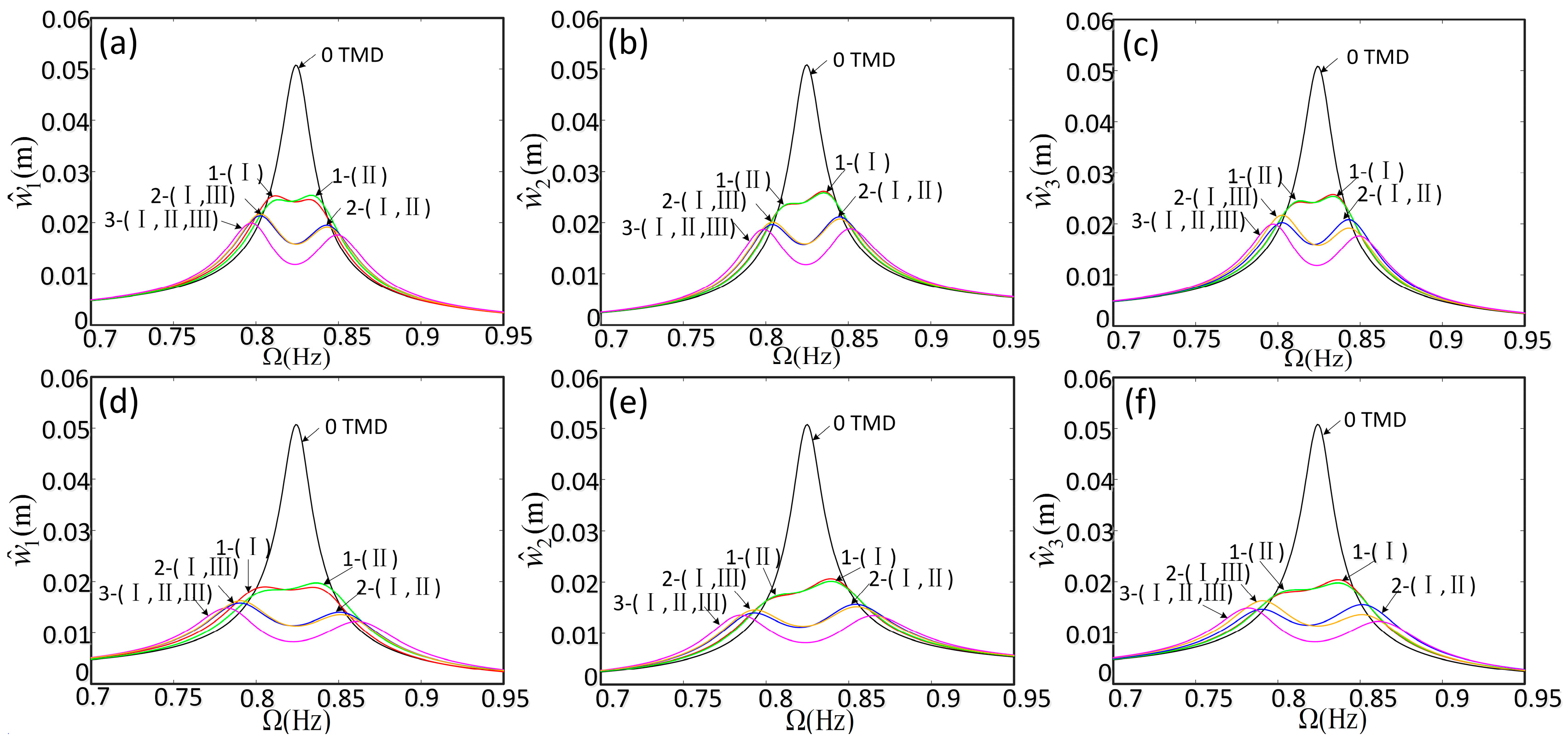
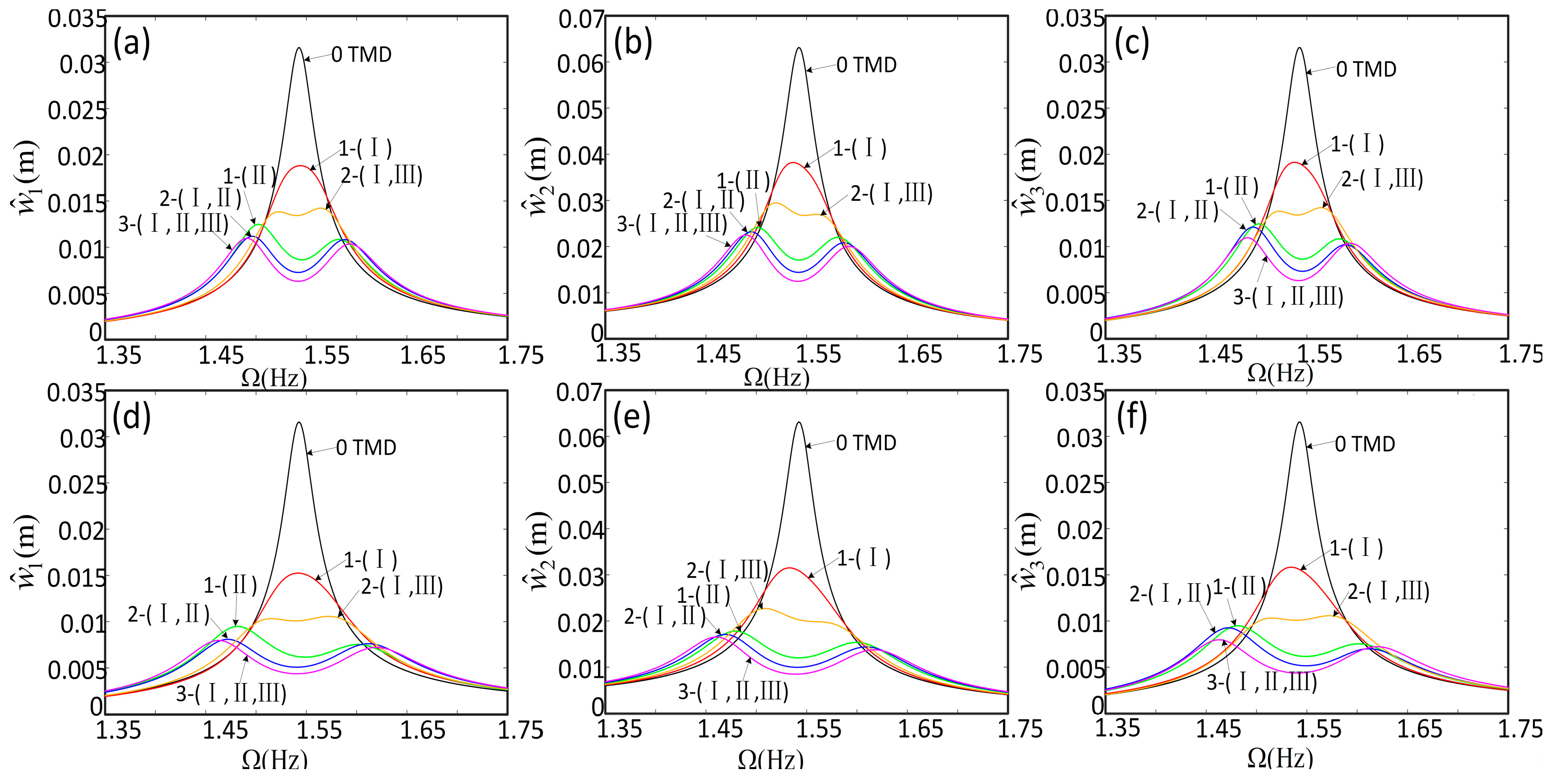
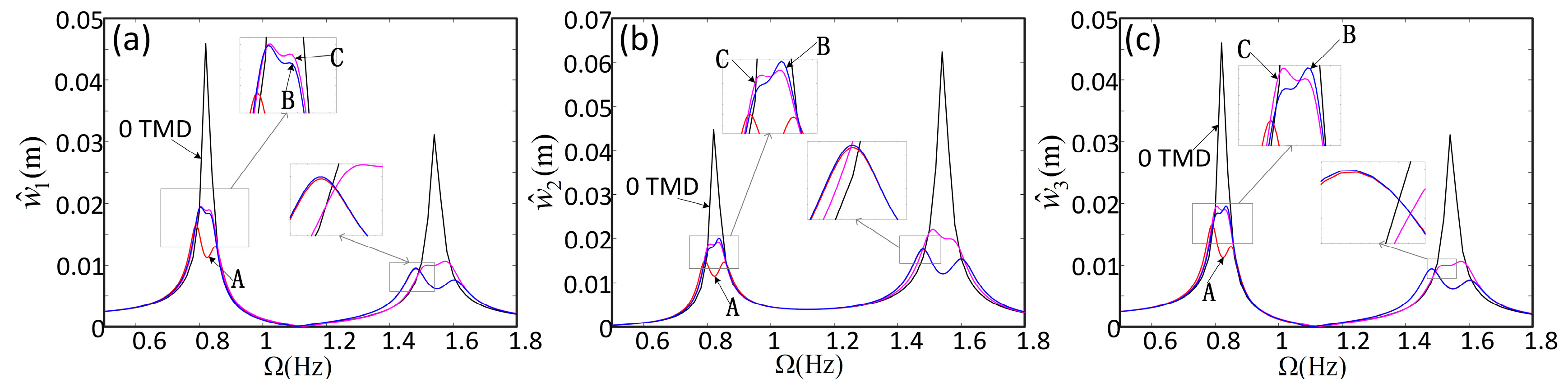
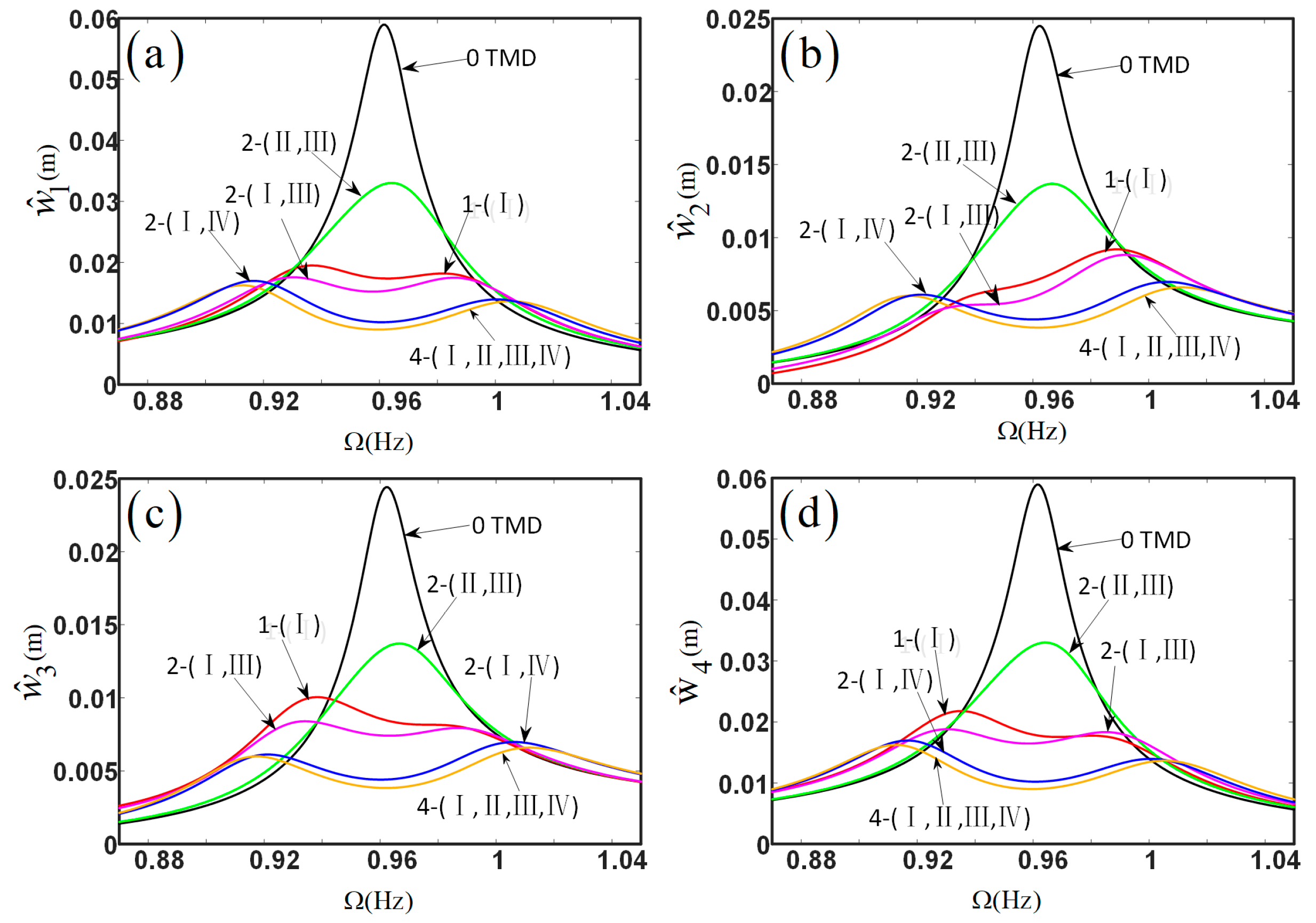
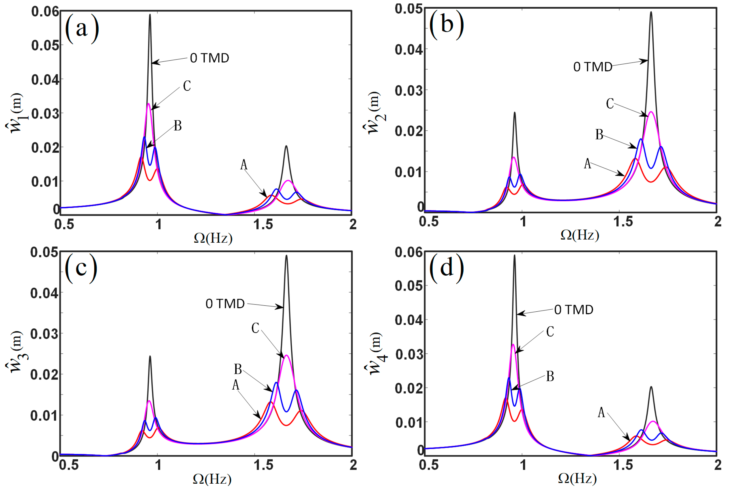
By comparing the natural frequencies calculated here with those obtained from the finite element software ANSYS, the validity of our approach has been verified. Then, based on the ODEs derived in the proposed model, the dynamic responses of three-span and four-span bridges have been calculated to study the influence of the location and number of TMDs on the vibration suppression of the bridge. The conclusions are summarized as follows:
(1)
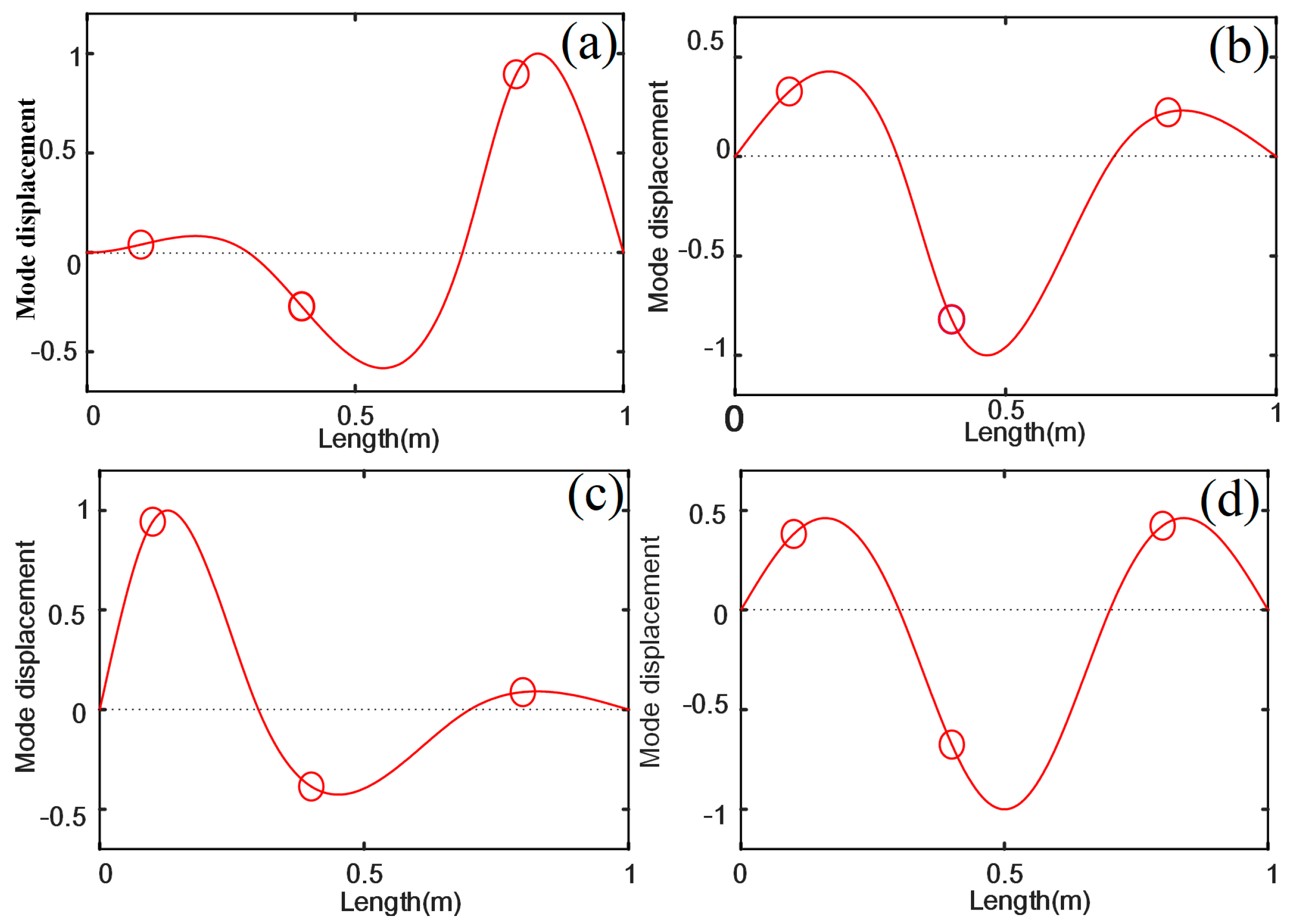
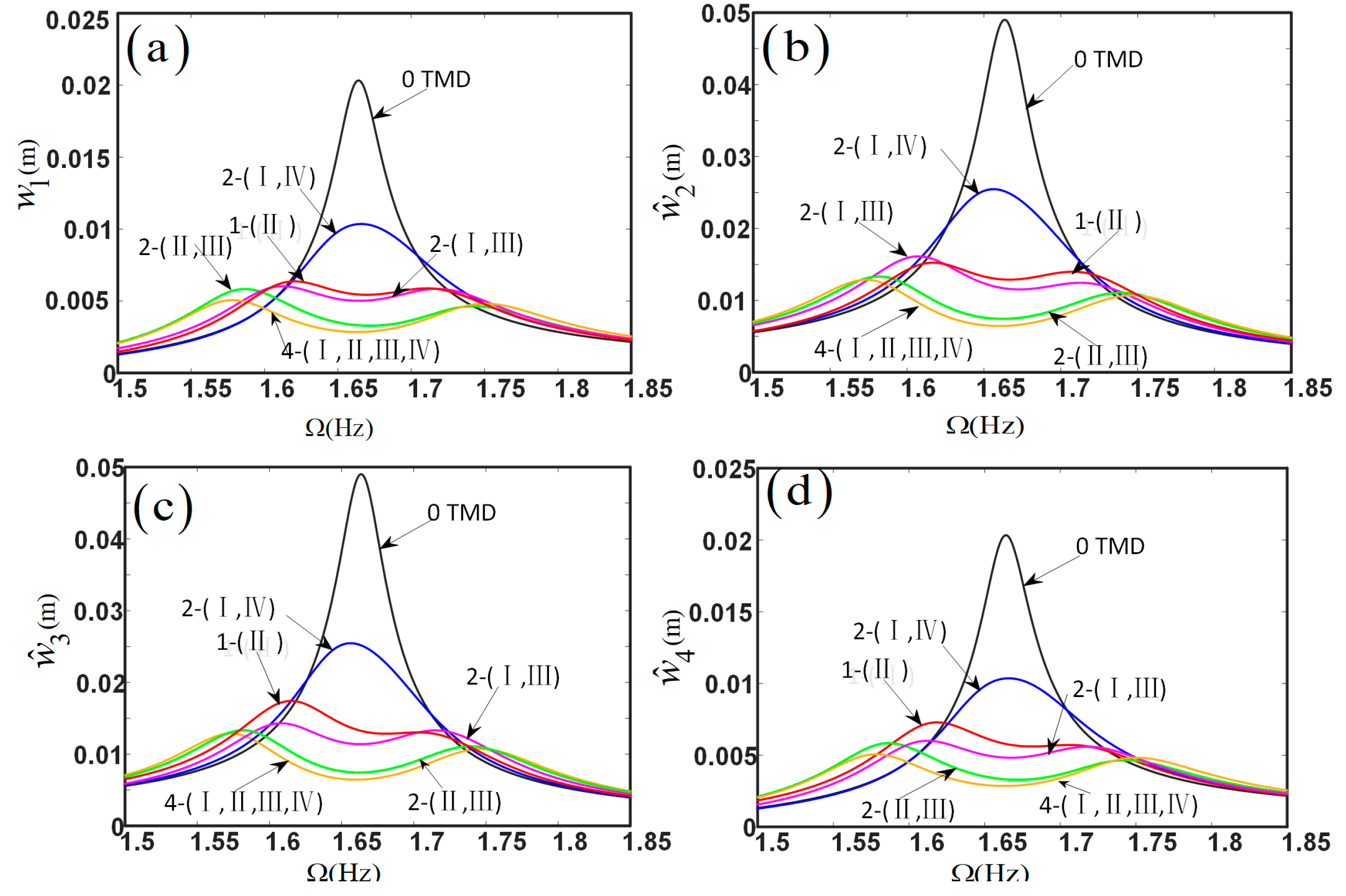
For the installation position of TMDs, the vibration suppression effect is closely related to the mode shape of the multi-span continuous bridge. When the TMD was installed at the point of maximum displacement in the mode shape of the bridge, its vibration suppression effect was the best, and the corresponding variation in the resonance frequency of the bridge was the largest.
(2)
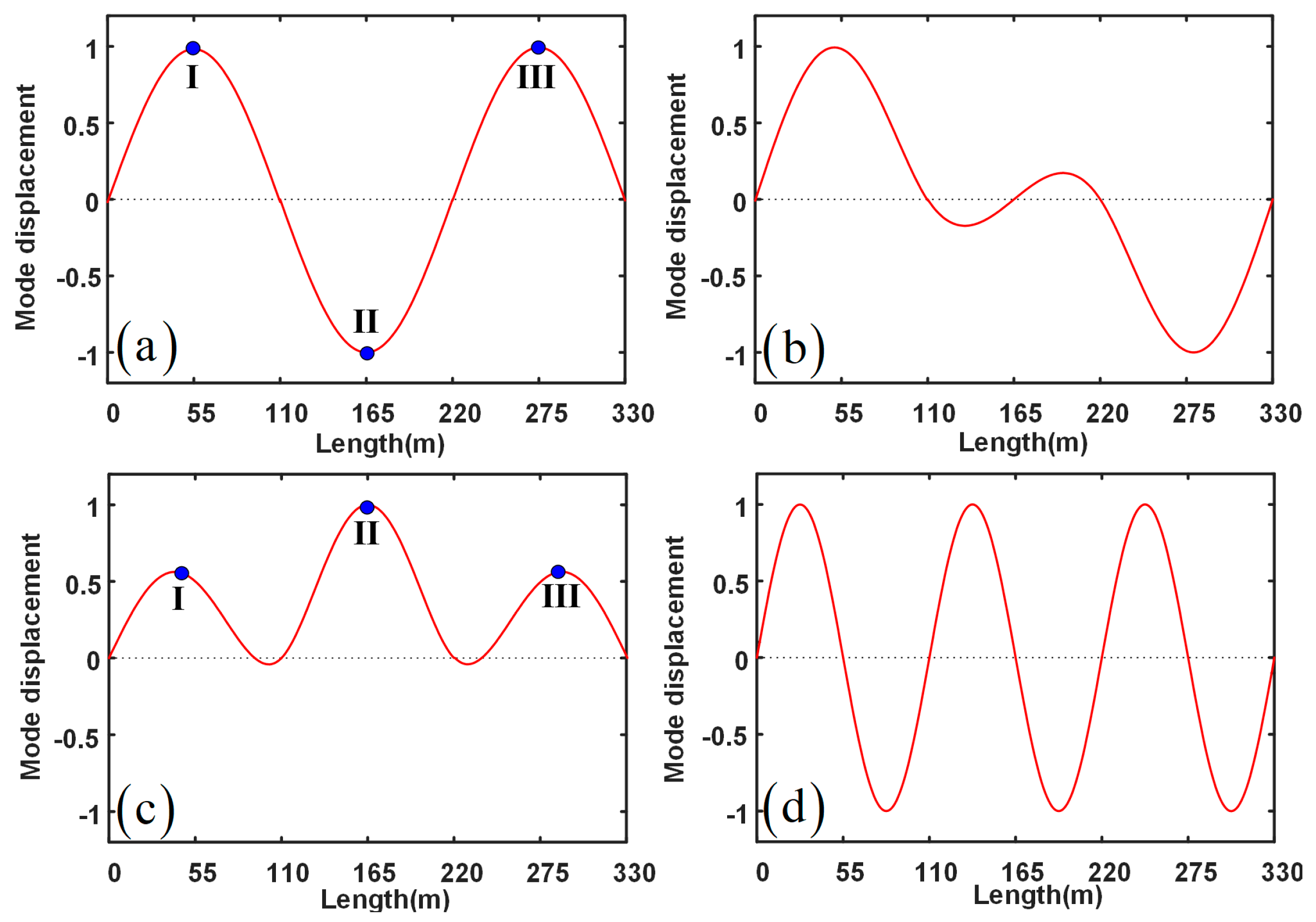
For the number of TMDs installed on a symmetrical multi-span continuous bridge, only one TMD needs to be installed at any point of maximum displacement in the mode shape of the bridge to have a good vibration suppression effect on the whole bridge. In this situation, when installing more TMDs at the other points of maximum displacement in the mode shape of the bridge, the improvement of the vibration reduction effect was not obvious.
In addition, the variable cross-section bridges are increasingly favored by long-span continuous multi-span bridges. In the future work, the method proposed in this paper will be applied to the dynamic modeling of continuous multi-span bridges with variable cross-sections.

Author Contributions

Conceptualization, J.W. and W.L.; methodology, J.W. and W.L.; software, W.L.; validation, W.L.; formal analysis, P.G.; investigation, J.W. and W.L.; resources, W.L. and P.G.; data curation, W.L.; writing—original draft preparation, W.L.; writing—review and editing, J.W. and W.L.; visualization, W.L.; supervision, J.W. and Y.D.; project administration, J.W. and Y.D.; funding acquisition, J.W. and Y.D. All authors have read and agreed to the published version of the manuscript.

Funding

This work was supported by the National Natural Science Foundation of China (Grant No. 12002298), the China Postdoctoral Science Foundation (Grant No. 2020M681578), and the Shandong Provincial Natural Science Foundation, China (Grant No. ZR2020QA038).

Institutional Review Board Statement

Not applicable.

Informed Consent Statement

Not applicable.

Data Availability Statement

Not applicable.

Conflicts of Interest

The authors declare no conflict of interest.

Appendix A

The relevant terms in Equation (28) are given as:
M b = [ M 1 M 2 0 0 M n ] , C b = [ c b 1 c b 2 0 0 c b n ] , K b = [ K 1 K 2 0 0 K n ] , M r = i = 1 N 1 l i 2 l i 2 ρ ϕ i r ( x ) ϕ i r ( x ) d x , K r = i = 1 N 1 l i 2 l i 2 E I ϕ i r ( x ) ϕ i r ( x ) d x , c b r = ξ ρ M r + η E K r , P = [ P 1 P 2 P n ] T , F r ( t ) = i = 1 N 1 L i 2 L i 2 f i ( x , t ) ϕ i r ( x ) d x , P r = [ P 1 r P 2 r P N 1 r ] , r = 1 , 2 , , m , P i r = [ ϕ i r ( a i 1 ) m i 1 ϕ i r ( a i 2 ) m i 2 ϕ i r ( a i N i ) m i N i ] , m = [ m 1 m 2 0 0 m N 1 ] , m i = [ m i 1 m i 2 0 0 m i N i ] , C T = [ C T 1 C T 2 C T n ] , C T r = [ C T 1 r C T 2 r C T N r ] , C T i r = [ ϕ i r ( a i 1 ) c i 1 ϕ i r ( a i 2 ) c i 2 ϕ i r ( a i N i ) c i N i ] , c = [ c 1 c 2 0 0 c N 1 ] , c i = [ c i 1 c i 2 0 0 c i N i ] , K T = [ K T 1 K T 2 K T n ] , K T r = [ K T 1 r K T 2 r K T N r ] , K T i r = [ ϕ i r ( a i 1 ) k i 1 ϕ i r ( a i 2 ) k i 2 ϕ i r ( a i N i ) k i N i ] , k = [ k 1 k 2 0 0 k N 1 ] , k i = [ k i 1 k i 2 0 0 k i N i ] .

References

  1. Wang, J.F.; Lin, C.C.; Chen, B.L. Vibration suppression for high-speed railway bridges using tuned mass dampers. Int. J. Solids Struct. 2003, 40, 465–491. [Google Scholar] [CrossRef]
  2. Li, J.; Su, M.; Fan, L. Vibration control of railway bridges under high-speed trains using multiple tuned mass dampers. J. Bridge Eng. 2005, 10, 312–320. [Google Scholar] [CrossRef]
  3. Ziyaeifar, M. Vibration control in train–bridge–track systems. Veh. Syst. Dyn. 2008, 46, 355–384. [Google Scholar] [CrossRef]
  4. Lin, C.C.; Wang, J.F.; Chen, B.L. Train-induced vibration control of high-speed railway bridges equipped with multiple tuned mass dampers. J. Bridge Eng. 2005, 10, 398–414. [Google Scholar] [CrossRef]
  5. Chen, Y.H.; Chen, D.S. Timoshenko beam with tuned mass dampers to moving loads. J. Bridge Eng. 2004, 9, 167–177. [Google Scholar] [CrossRef]
  6. Zhou, D.F.; Hansen, C.H.; Li, J. Suppression of maglev vehicle–girder self-excited vibration using a virtual tuned mass damper. J. Sound Vib. 2011, 330, 883–901. [Google Scholar] [CrossRef]
  7. Dyniewicz, B.; Konowrocki, R.; Bajer, C.I. Intelligent adaptive control of the vehicle-span/track system. Mech. Syst. Sig. Process. 2015, 58–59, 1–14. [Google Scholar] [CrossRef]
  8. Chen, J.; Chen, M.Z.Q.; Hu, Y. Vortex-induced vibration suppression of bridges by inerter-based dynamic vibration absorbers. Shock Vib. 2021, 2021, 4431516. [Google Scholar] [CrossRef]
  9. Xu, K.; Bi, K.; Han, Q.; Li, X.; Du, X. Using tuned mass damper inerter to mitigate vortex-induced vibration of long-span bridges: Analytical study. Eng. Struct. 2019, 182, 101–111. [Google Scholar] [CrossRef]
  10. Andersen, L.; Birch, N.W.; Hansen, A.H.; Skibelund, J.O. Response analysis of tuned mass dampers to structures exposed to vortex loading of simiu-scanlan type. J. Sound Vib. 2001, 239, 217–231. [Google Scholar] [CrossRef]
  11. Dai, J.; Xu, Z.D.; Gai, P.P. Parameter determination of the tuned mass damper mitigating the vortex-induced vibration in bridges. Eng. Struct. 2020, 221, 111084. [Google Scholar] [CrossRef]
  12. Ehsan, F.; Scanlan, R.H.; Bosch, H.R. Modeling spanwise correlation effects in the vortex-induced response of flexible bridges. J. Wind Eng. Ind. Aerodyn. 1990, 36, 1105–1114. [Google Scholar] [CrossRef]
  13. Dai, J.; Xu, Z.D.; Gai, P.P.; Xu, Y.W. Mitigation of vortex-induced vibration in bridges using semiactive tuned mass dampers. J. Bridge Eng. 2021, 26, 05021003. [Google Scholar] [CrossRef]
  14. Domaneschi, M.; Martinelli, L.; Po, E. Control of wind buffeting vibrations in a suspension bridge by TMD: Hybridization and robustness issues. Comput Struct. 2015, 155, 3–17. [Google Scholar] [CrossRef]
  15. Di Matteo, A.; Masnata, C.; Pirrotta, A. Simplified analytical solution for the optimal design of tuned mass damper inerter for base isolated structures. Mech. Syst. Sig. Process 2019, 134, 106337. [Google Scholar] [CrossRef]
  16. Asai, T.; Araki, Y.; Ikago, K. Energy harvesting potential of tuned inertial mass electromagnetic transducers. Mech. Syst. Sig. Process. 2017, 84, 659–672. [Google Scholar] [CrossRef]
  17. Pellizzari, F.; Marano, G.C.; Palmeri, A.; Greco, R.; Domaneschi, M. Robust optimization of MTMD systems for the control of vibrations. Probabilist Eng. Mech. 2022, 70, 103347. [Google Scholar] [CrossRef]
  18. Miguel, L.F.F.; Lopez, R.H.; Torii, A.J.; Miguel, L.F.F.; Beck, A.T. Robust design optimization of TMDs in vehicle–bridge coupled vibration problems. Eng. Struct. 2016, 126, 703–711. [Google Scholar] [CrossRef]
  19. Jin, X.; Chen, M.Z.Q.; Huang, Z. Minimization of the beam response using inerter-based passive vibration control configurations. Int. J. Mech. Sci. 2016, 119, 80–87. [Google Scholar] [CrossRef]
  20. Zheng, D.Y.; Cheung, Y.K.; Au, F.T.K.; Cheng, Y.S. Vibration of multi-span non-uniform beams under moving loads by using modified beam vibration functions. J. Sound Vib. 1998, 212, 455–467. [Google Scholar] [CrossRef]
  21. Luu, M.; Zabel, V.; Könke, C. An optimization method of multi-resonant response of high-speed train bridges using TMDs. Finite Elem. Anal. Des. 2012, 53, 13–23. [Google Scholar] [CrossRef]
  22. Fujino, Y.; Yoshida, Y. Wind-induced vibration and control of trans-tokyo bay crossing bridge. J. Struct. Eng. 2002, 128, 1012–1025. [Google Scholar] [CrossRef]
  23. Battista, R.C.; Pfeil, M.S. Reduction of vortex-induced oscillations of Rio–Niterói bridge by dynamic control devices. J. Wind Eng. Ind. Aerodyn. 2000, 84, 273–288. [Google Scholar] [CrossRef]
  24. Sgobba, S.; Marano, G.C. Optimum design of linear tuned mass dampers for structures with nonlinear behaviour. Mech. Syst. Sig. Process. 2010, 24, 1739–1755. [Google Scholar] [CrossRef]
  25. Matin, A.; Elias, S.; Matsagar, V. Distributed multiple tuned mass dampers for seismic response control in bridges. Proc. Inst. Civ. Eng. Struct. Build. 2019, 173, 217–234. [Google Scholar] [CrossRef]
  26. Crespi, P.; Zucca, M.; Longarini, N.; Giordano, N. Seismic assessment of six typologies of existing RC bridges. Infrastructures 2020, 5, 52. [Google Scholar] [CrossRef]
  27. Crespi, P.; Zucca, M.; Valente, M. On the collapse evaluation of existing RC bridges exposed to corrosion under horizontal loads. Eng. Fail Anal. 2020, 116, 104727. [Google Scholar] [CrossRef]
  28. Ichikawa, M.; Miyakawa, Y.; Matsuda, A. Vibration analysis of the continuous beam subjected to a moving mass. J. Sound Vib. 2000, 230, 493–506. [Google Scholar] [CrossRef]
  29. Lin, H.Y.; Tsai, Y.C. Free vibration analysis of a uniform multi-span beam carrying multiple spring–mass systems. J. Sound Vib. 2007, 302, 442–456. [Google Scholar] [CrossRef]
  30. Wei, J.; Cao, D.Q.; Liu, L.; Huang, W.H. Global mode method for dynamic modeling of a flexible-link flexible-joint manipulator with tip mass. Appl. Math. Modell. 2017, 48, 787–805. [Google Scholar] [CrossRef]
  31. Wei, J.; Yu, T.; Jin, D.P.; Liu, M.; Cao, D.Q.; Wang, J.J. Nonlinear dynamic modeling and analysis of an L-shaped multi-beam jointed structure with tip mass. Materials. 2021, 14, 7279. [Google Scholar] [CrossRef] [PubMed]
  32. Wei, J.; Cao, D.Q.; Huang, H.; Wang, L.C.; Huang, W.H. Dynamics of a multi-beam structure connected with nonlinear joints: Modelling and simulation. Arch. Appl. Mech. 2018, 88, 1059–1074. [Google Scholar] [CrossRef]
  33. Wei, J.; Cao, D.Q.; Huang, H. Nonlinear vibration phenomenon of maneuvering spacecraft with flexible jointed appendages. Nonlinear Dyn. 2018, 94, 2863–2877. [Google Scholar] [CrossRef]
  34. Wei, J.; Cao, D.Q.; Wang, L.C.; Huang, H.; Huang, W.H. Dynamic modeling and simulation for flexible spacecraft with flexible jointed solar panels. Int. J. Mech. Sci. 2017, 130, 558–570. [Google Scholar] [CrossRef]
  35. Ehsan, F.; Scanlan Robert, H. Vortex-induced vibrations of flexible bridges. J. Eng. Mech. 1990, 116, 1392–1411. [Google Scholar] [CrossRef]
  36. Den Hartog, J.P. Mechanical Vibrations; McGraw-Hill Book Company: New York, NY, USA; London, UK, 1934. [Google Scholar]
Figure 1. Schematic diagram of a multi-span continuous bridge with TMDs.
Jmse 11 01017 g001
Figure 2. Schematic diagram of a bridge system.
Jmse 11 01017 g002
Figure 3. The first four mode shapes of the bridge system: (ad) the first to fourth mode shapes.
Jmse 11 01017 g003
Figure 4. The first four mode shapes of the three-span bridge: (ad) the first to fourth mode shapes.
Jmse 11 01017 g004
Figure 5. Frequency–response curves of three-span bridge for the resonant response of the first mode: (ac): the first to third spans μ = 0.2 % , and (df): the first to third spans μ = 0.5 % .
Jmse 11 01017 g005
Figure 6. Frequency–response curves of a three-span bridge for the resonant response of the third mode: (ac): the first to third spans μ = 0.2 % , and (df): the first to third spans μ = 0.5 % .
Jmse 11 01017 g006
Figure 7. Frequency–response curves of a three-span bridge for the resonant response of the first and third modes: (ac): the first to third spans μ = 0.5 % .
Jmse 11 01017 g007
Figure 8. The first four mode shapes of a four-span bridge: (ad) the first to fourth mode shapes.
Jmse 11 01017 g008
Figure 9. Frequency–response curves of a four-span bridge for the resonant response of the second mode: (ad): the first to fourth spans μ = 0.5 % .
Jmse 11 01017 g009
Figure 10. Frequency–response curves of a four-span bridge for the resonant response of the fourth mode: (ad): the first to fourth spans μ = 0.5 % .
Jmse 11 01017 g010
Figure 11. Frequency–response curves of a four-span bridge for the resonant response of the second and fourth modes: (ad): the first to fourth spans μ = 0.5 % .
Jmse 11 01017 g011
Table 1. Parameter values for the bridge system.
ParameterValue
Beam mass density, ρ   ( kg / m ) 15.3875
Beam elastic modulus, E   ( Pa ) 2.069 × 10 11
Beam diameter, d   ( m ) 0.05
Mass of first spring-mass, m 1   ( kg ) 3.0775
Mass of second spring-mass, m 2   ( kg ) 4.6163
Mass of third spring-mass, m 3   ( kg ) 7.6938
Stiffness of first spring-mass, k 1 ( N / m ) 1.9043 × 10 5
Stiffness of second spring-mass, k 2 ( N / m ) 2.2217 × 10 5
Stiffness of third spring-mass, k 3 ( N / m ) 2.8564 × 10 5
Table 2. The five lowest natural frequencies of the bridge system, ω   ( Hz ) .
ω 1 ω 2 ω 3 ω 4 ω 5
Proposed model30.64634.89439.570835.9641367.950
Model from ANSYS30.56734.81539.504835.9571367.962
Table 3. The values of R i on the three-span bridge for the resonant response of the first mode.
Cases R 1 R 2 R 3
μ = 0.2 % μ = 0.5 % μ = 0.2 % μ = 0.5 % μ = 0.2 % μ = 0.5 %
1 ( I ) 50.4 % 62.6 % 48.6 % 59.4 % 49.2 % 59.8 %
1 ( II ) 50.2 % 61.0 % 49.0 % 60.2 % 50.0 % 61.0 %
2 ( I , II ) 58.1 % 68.9 % 58.5 % 69.1 % 59.1 % 69.5 %
2 ( I , III ) 57.5 % 68.1 % 59.3 % 70.1 % 57.3 % 67.9 %
3 ( I , II , III ) 60.6 % 70.9 % 63.0 % 73.2 % 60.8 % 70.7 %
Table 4. The values of R i on the three-span bridge for the resonant response of the third mode.
Cases R 1 R 2 R 3
μ = 0.2 % μ = 0.5 % μ = 0.2 % μ = 0.5 % μ = 0.2 % μ = 0.5 %
1 ( I ) 40.5 % 51.6 % 39.5 % 50.1 % 39.6 % 50.0 %
1 ( II ) 60.4 % 69.9 % 61.8 % 71.8 % 60.4 % 69.9 %
2 ( I , II ) 64.6 % 74.4 % 63.2 % 72.9 % 61.7 % 70.9 %
2 ( I , III ) 55.1 % 66.5 % 53.2 % 64.0 % 55.1 % 66.5 %
3 ( I , II , III ) 65.2 % 74.7 % 64.3 % 73.9 % 65.2 % 74.7 %
Table 5. The values of R i on the four-span bridge for the resonant response of the second mode.
Cases R 1 R 2 R 3 R 4
1 ( I ) 66.9 % 62.4 % 59.2 % 63.1 %
2 ( I , III ) 70.2 % 64.1 % 65.7 % 68.1 %
2 ( I , IV ) 71.2 % 71.4 % 71.4 % 71.2 %
2 ( II , III ) 44.1 % 44.1 % 44.1 % 44.1 %
4 ( I , II , III , IV ) 71.2 % 73.1 % 73.1 % 71.2 %
Table 6. The values of R i on the four-span bridge for the resonant response of the fourth mode.
Cases R 1 R 2 R 3 R 4
1 ( II ) 68.5 % 68.8 % 64.5 % 64.0 %
2 ( I , III ) 70.4 % 67.1 % 70.8 % 70.4 %
2 ( I , IV ) 48.8 % 48.0 % 48.0 % 48.8 %
2 ( II , III ) 71.4 % 72.9 % 72.9 % 71.4 %
4 ( I , II , III , IV ) 74.9 % 73.7 % 73.7 % 74.9 %
Disclaimer/Publisher’s Note: The statements, opinions and data contained in all publications are solely those of the individual author(s) and contributor(s) and not of MDPI and/or the editor(s). MDPI and/or the editor(s) disclaim responsibility for any injury to people or property resulting from any ideas, methods, instructions or products referred to in the content.

