Article

A Small Floating Platform Designed for Unmanned Defense System

1
School of Mechanical Engineering, Nanjing University of Science and Technology, Nanjing 210094, China
2
Hubei Academy of Aerospace Technology, Wuhan 430043, China
3
Road Machinery Branch of Xugong Group Construction Machinery Co., Ltd., Xuzhou 221004, China
4
Hainan Institute, Zhejiang University, Sanya 572025, China
*
Author to whom correspondence should be addressed.
These authors contributed equally to this work.
J. Mar. Sci. Eng. 2023, 11(2), 278; https://doi.org/10.3390/jmse11020278
Submission received: 3 December 2022 / Revised: 22 January 2023 / Accepted: 23 January 2023 / Published: 26 January 2023
(This article belongs to the Special Issue Advances in Marine Structures)

Abstract

:
A small floating platform designed for an unmanned short-range defense system is proposed. The structures of the proposed floating platform and weapon system are detailed and described. The floating platform is investigated via virtual prototype technology in the aspects of the platform motion under sea waves of up to Beaufort wind and Douglas sea (wind-sea) scale 5. The motion equations of the floating platform are established according to the ship motion theory, and the movement of the floating platform under different wind-sea scales are simulated and analysed via multi-body fluid dynamics analysis software. To decide the proper size of the platform, the dynamic response of the floating platforms with different sizes is analysed and evaluated under various sea conditions based on multi-body dynamics. A scaled model experiment was conducted and compared with simulation results to verify the theoretical model. A verification experiment was also conducted in a water tank for the performance of the platform via simulated wave disturbance. Results show that the designed floating platform could provide a stable platform in the horizontal direction under a wind-sea scale 3 environment for the defense weapon system, which well meets the design requirement.

1. Introduction

Presently, the world is facing significant challenges in terms of energy shortage, environmental pollution, greenhouse gas emission, and energy supply in rural areas, which give rise to a heavy burden on sustainable development [1,2]. Renewable energy has been attracting attention worldwide in order to tackle these issues. In this situation, the ocean has become one of the goals for countries to compete for due to its huge economic, political, and military interest.
Unmanned offshore platforms can be used as both civil and military equipment. For example, tension-leg platform (TLP), spar, and Floating Production Storage and Offloading (FPSO) have been widely used for oil and wind turbine systems in deep water, with huge size, complex control ability, and poor mobility and flexibility [3,4,5,6]. The unmanned naval vessels, equipped with advanced control systems and communication systems, can carry out ocean reconnaissance and anti-submarine operations, but they generally operate in offshore waters, and the overall system is relatively large and complex. The shipborne platform is mainly used for the takeoff and landing of large shipborne unmanned aerial vehicles (UAVs), with strong load capacity and lack of flexibility [7].
A floating platform is susceptible to large oscillations such as the aerodynamic force of wind and the hydrodynamic force of the wave, which may compromise its performance and structural stability [8]. In particular, the offshore platform tends to have a swaying motion induced by sea waves, including multi-dimensional motions such as roll and pitch [9], which could reach up to 10° and angular velocity up to 10°/s [10]. Therefore, to provide a stable platform for the integrated instrument, the platform must be capable of adjusting its inclination induced by sea waves [11].
Uncontrollable inclination can cause unexpected damage, such as interference and collision between the floating body and other objects or other floating bodies, especially if the two floating bodies need to be in a relative static position relationship. Although there are many ways to deal with damage, collision reduction methods, materials, or devices have been proposed [12,13,14,15]. However, it is more important to consider the mechanism of floating body sloshing to restrain a floating body’s motion induced by sea waves. Since the 1940s, researchers have begun to focus on the hydrodynamic theory of ship sway, and Green’s function was applied to establish the hull disturbance velocity potential function to solve the ship motion problem, which is still an important model for the swaying problem to this day [16]. After the 1950s, the slicing theory proposed by Corvin-kraukowski [17] and its improved methods has been developed to calculate ship motion in oblique waves, which can be used for solving ship motion of six degrees of freedom (DOF) [16]. Along with the development of the slicing theory, the three-dimensional theory of hydrodynamic calculation of ship motion has also been developed. Compared with the slicing theory, it has higher calculation accuracy and is closer to the test results. In recent years, nonlinear ship motion has attracted great attention, such as the second-order steady wave drift force and slow-varying wave drift force suffered by ships and marine engineering structures [18]. When analysing the motion of offshore floating platforms under random waves, the analysis method of ship motion for reference [19,20] can be used. However, there are still some differences between the floating platform structure and the ship structure. Therefore, it is necessary to analyse the movement characteristics of offshore floating platforms according to their specific characteristics.
An unmanned platform is one of the best ways to realize surface information perception, early warning, and reconnaissance. A small-size floating platform on the water surface, which is portable and easy to release, provides a stable platform for information detection on the sea surface. The structure of the floating platform currently designed is mainly different from that of the ship structure in aspect ratio. The overall height of the floating platform is much larger than the diameter/width/length, while the overall height of the ship is generally smaller than the width or length of the ship. This is the main difference between the floating platform and the ship, which leads to the stability problem of the floating platform in the wave environment. Therefore, it is necessary to compensate for or control the influence of waves. In addition, the small scale platform in this paper mainly refers to the small ratio between the feature size of the floating platform and the wavelength, and a ratio less than 0.2 is called small scale.
Previous studies on the dynamic response of floating platforms mainly focused on large-sized, hinged, or single floating platforms. This paper proposes a small floating platform designed for a short-range defense system, which could buy time for the retreat of valuable objects from the enemy air force. The influence of ocean waves on the working performance of the floating platform is investigated in this paper. The dynamic model of the multi-body system is established based on the research method of the shipborne rocket weapon, and its dynamic characteristics are studied in theory and simulation. The dynamic response of the floating platforms with different sizes is analysed and evaluated under various sea conditions based on multi-body dynamics to decide the proper size of the platform. A preliminary floating test was carried out using a scaled platform and scaled wave generation, followed by a verification experiment in a water tank, to verify the performance of the platform.

2. System Structural Design

2.1. Design Requirement

The defense system needs to work at wind-sea scale 3 wave conditions, and the entire platform cannot exceed the swaying range of ±15°. The wave classification standards are shown in Table 1.
The structural design of the overall system is shown in Figure 1, which is mainly composed of a floating platform, a weapon system (including an infrared detector, rotating parts, pitching parts, and base components), and a self-leveling system. The floating platform is designed to carry the whole weapon system, enabling the system to float on the sea surface and resist wave-caused swaying motion. Then, the weapon system searches for and locks the target utilizing the infrared detector. In order to compensate for the wave-induced swaying angle on the weapon system, a real-time leveling system is attached at the bottom of the system. The total load carried by the floating platform is 262.82 kg including the search aiming system, and the displaced volume is V = 262.82 + 22 1025 = 0.278 m3.

2.2. Structural Design

Four inflatable rubber airbags are preliminarily selected as the main frame of the floating platform, as shown in Figure 2.
The four airbags are overlapped together and rigidly connected with the fixed support of the weapon system through bolts to form an intersecting parallel shape. The airbag is inflated and opened by the gas generating device after being initiated at the target location. Airbag diameter and length are the main design variables, which can be determined by the following aspects: (a) The airbag can provide enough buoyancy for the defense system; (b) The platform can reduce the swaying angle within ±15°, creating a good environment for the leveling system. For the former, it can be obtained via the buoyancy equation F f l o a t i n g = ρ w a t e r g v = G s y s t e m , and the displaced volume is V = G s y s t e m ρ w a t e r g = M ρ w a t e r .

3. Methods

When a floating platform deviates from its initial equilibrium position under the impact of sea waves, the ability to recover the initial equilibrium position by itself is called stability. According to different inclination angles, the stability can be divided into the initial stability and the large inclination stability. The inclination for initial stability is less than 10~15°, and the large inclination stability inclination is greater than 15°. In this study, to reduce the workload of the leveling system, the swaying angle of the floating platform needs to be within 15°. The swaying of the platform with different sizes can be obtained by adjusting the platform size, which is selected based on the initial stability angles.

3.1. Motion Equation of Floating Platform

The force induced by the wind and waves could lead to the swaying motion of the floating platform. The basic form of sway motion includes roll, pitch, yaw, heave, sway, and surge, as shown in Figure 3. The direction of the coordinate system in Figure 3 is the same as that of the fixed coordinate system of the weapon system, where the origin is located in the static water surface, with x axis parallel to the pitch drive side, and y axis points to the direction of the gun tube at the angle of 0°, perpendicular to the waterline. Roll is the floating platform sway around x axis, and the roll angle is φ . Pitch is the floating platform sway around the y axis, and the pitch angle is θ . Yaw is the floating platform sway around the z axis, and the yaw angle is ψ .
This study adopts linear wave theory for motion calculations [20,21]. According to the analysis of ship swaying motion in the linear range, assuming that the platform swaying angle has a small range, it should be solved in the linear range. Therefore, the hydrodynamic calculation of the platform swaying in regular waves can be decomposed into the solution of the radiation problem and the diffraction problem. The radiation problem only considers the forced oscillation of the platform in still water. In the diffraction problem, it is assumed that the platform is in the equilibrium position; there is no rocking motion, only the action of wave incident wave. According to the force balance, the hydrodynamic force in these two kinds of problems is balanced with the hydrostatic restoring force of the platform and the inertia force of the platform rocking, which makes the problem solved. The problem of irregular waves can be regarded as the linear superposition of many regular waves.
According to the principle of force balance, the hydrodynamic force in these two kinds of problems is balanced with the hydrostatic restoring force of the platform and the inertial force of the platform swaying. Then, it can be solved via the statistical value of platform swaying in irregular waves by using spectral analysis.
It is assumed that the water environment is an ideal fluid which is uniform, incompressible, and non-viscous. The flow field satisfies the following conservation law [22]: Equation of continuity and Euler equation:
· v = 0
( t + v · ) v = ( p ρ + g y )
where v ( x , y , z , t ) is the velocity vector; p ( x , y , z , t ) is pressure; ρ is the density of water. As the curl in the irrotational flow field is zero, then:
Ω = × v = 0
The velocity potential function ϕ ( x , y , z , t ) in the irrotational flow field satisfies
v = ϕ ( x , y , z , t )
which also yields to the Laplace equation 2 ϕ ( x , y , z , t ) = 0 , expressed in rectangular coordinates by:
2 ϕ x 2 + 2 ϕ y 2 + 2 ϕ z 2 = 0
In combination with the above equations,
p ρ + g y + v 2 2 + φ t = C ( t )
where C ( t ) is a function of time t.
After the constant velocity potential is obtained, the pressure distribution of the flow field can be calculated according to the Lagrangian integral formula Equation (6), to further determine the fluid force exerted on the platform and establish the differential equation of the platform motion.
In order to make the solution of the Lagrangian equation unique, the following boundary conditions should be applied:
  • Boundary conditions on the platform surface:
From the impenetrability of the material surface, it can be obtained that:
φ n | S = U n
where the left side of Equation (7) represents the normal velocity of a mass point on the surface S of the object, and the right side represents the normal projection of the motion velocity of a point on the surface S. The equation indicates that there is no liquid flow in or out of the object when the normal velocity at any point of surface S is equal to the normal velocity of any fluid mass point close to this point.
  • Boundary conditions on the free surface:
A free surface is often thought of as a flat surface of z = 0 , that is, an undisturbed still surface. In the secondary plane,
2 ϕ 2 t + g ϕ z = 0
  • Radiation conditions:
For linear hydrodynamic problems caused by finite range disturbances,
lim R R ( ϕ R + 1 C ϕ t ) = 0
where R is the horizontal distance from a point at infinity to the disturbance, and C is the wave propagation velocity.
  • Infinite water depths meet:
lim y ϕ = 0
indicating that the influence of disturbance decreases with the increase in water depth.

3.2. The Motion Equation of the Floating Platform

Newton’s momentum theorem and moment of momentum theorem of rigid body mechanics can be used to establish the equations of the platform motion, including three translational equations and three rotational equations [23,24,25,26,27]. The momentum and momentum moment theorems are:
d G d t = F
d Q d t = M
where G is the rigid body momentum; Q is the momentum distance around the mass center; F is the resultant of the external force acting on the particle; M is the external torque around the mass center.
To simplify the calculation, it is assumed that the moving coordinate system of the platform is located at the mass center of the platform, that is, the origin is at the mass center of the platform, then:
d G d t = d ( M v ) d t = M ( v t + ω × v ) = F
d Q d t = ( I ω ) t = I ( ω t + ε × ω ) = M
where M is the mass of the rigid body, v is the motion velocity of the mass center, ω is the angular velocity of rotation around an instantaneous axis of the mass center, and I is the moment of inertia around an instantaneous axis of the mass center.
As the platform motion is within a small angle range, the nonlinear influence can be ignored and only the first-order linear response needs to be considered. Equations (13) and (14) can be simplified as:
M v t = F
I ω t = M
In order to simply the six degrees of freedom motion of the platform, a matrix
[ m i j ] = [ M M 0 M I 11 I 12 I 13 0 I 21 I 22 I 23 I 31 I 32 I 33 ]
and a vector: { x j } = { x ¯ , y ¯ , z ¯ , α , β , γ } are introduced, where x , y , z are the displacements and α , β , γ are the angular rotations.
Equations (15) and (16) then can be written as
m i j x ¨ j = N i ( i , j = 1 , 2 , 3 , 4 , 5 , 6 )
where N i is the combined external forces or external torques acting on the platform, which is the general description of the linear motion equation of the floating platform on the waves.
When the platform is swaying, the forces acting on the platform mainly include the wave-induced disturbing force, the fluid reaction force generated by the platform swaying, the static restoring force generated by an off-balance position, and external forces such as wind-caused force, where the former two are called fluid forces. The fluid force and torque are equal to the integral of fluid pressure acting on the normal surface of the platform along the wetted surface of the platform.
Pressure p can be calculated by the velocity potential function ϕ according to the linear Lagrangian integral:
p ( x , y , z , t ) = ρ ϕ t ρ g z
Then the fluid force F on the platform is:
F i = S p n i d S       i = 1 , 2 , 3
and the torque M is:
M i = S p ( r × n ) i d S       i = 1 , 2 , 3
where r is the vector diameter from a point on the surface to the origin of the moving coordinate system, and n is the unit normal vector of the platform surface.
Substitute Equation (19) into Equations (20) and (21) to get:
F i = ρ S g z n i d S ρ S ϕ t n i d S
M ´ i = ρ S g z ( r × n ) i d S ρ S φ t ( r × n ) i d S
As the movement of the platform is within a small angle range, and the difference between the instantaneous wet surface S when swaying and the stationary wet surface S0 is insignificant, S can thus be replaced by S0:
F i ( d ) = ρ S 0 ϕ t n i d S
M i ( d ) = ρ S 0 φ t ( r × n ) i d S
The Equations (24) and (25) are expressed by a generalized coordinate vector as:
F i ( d ) = ρ S 0 φ t n i d S       i = 1 , 2 , 3 , 4 , 5 , 6
and the rest are static terms. Equation (26) describes the main driving force of the platform’s swaying motion.
The total velocity potential in the flow field can be decomposed into constant wave potential ϕ ¯ ( x , y , z ) , incident wave velocity potential ϕ I ( x , y , z , t ) , diffraction velocity potential ϕ D ( x , y , z , t ) and radiation velocity potential ϕ R ( x , y , z , t ) ; then the total velocity potential is expressed by:
ϕ = ϕ ¯ + ϕ I + ϕ D + ϕ R
In addition, the radiation velocity potential can also be expressed as:
φ R = x ˙ o j φ j       ( j = 1 , 2 , 3 , 4 , 5 , 6 )
where x o j is the oscillating motion displacement, and ϕ j is the normalized velocity potential corresponding to the motion mode j .
Substitute Equations (27) and (28) into Equation (26):
F i ( d ) = ρ S 0 ϕ I t n i d S ρ S 0 ϕ D t n i d S ρ S 0 x ˙ o j ϕ j t n i d S
where the first two elements are wave disturbing forces, denoted as:
F w i = F w i k + F w i d
where F w i k = ρ i ω S 0 ϕ I n i d S , and F w i d = ρ i ω S 0 ϕ D n i d S ,
and the third term is the fluid reaction force on the platform, denoted as:
F R = x ¨ o j μ i j x ˙ o j λ i j
where μ i j is the additional mass coefficient, and λ i j is the additional damping coefficient.
In Equation (26), the static term is the restoring force and moment of the platform sway motion, denoted as
F i ( s ) = C i j · x o j       i , j = 1 , 2 , 3 , 4 , 5 , 6
where { x o j } = ( x ¯ , y ¯ , z ¯ , α , β , γ ) , and { C i j } is the coefficient matrix of restoring force.
The wind load calculation is based on:
F w = C j ( θ ) × v 2
where C j is the wind coefficient corresponding to different wind direction angles θ , and v is the wind speed on the platform surface.
The specific motion equation of the platform on waves can be derived by substituting Equations (30)–(33) into Equation (18):
( m i j + μ i j ) x ¨ o j + λ o j x ˙ o j + C i j x o j = F w i k + F w i d + F w       i , j = 1 , 2 , 6

3.3. Description of Waves

The irregularity of sea waves brings many difficulties to the mathematical wave description. The most commonly used mathematical method is the wave energy spectrum method. In this method, it is assumed that waves are two-dimensional, that is, waves are only generated in a plane, with only one fixed advance direction for each wave, and an infinitely long crest line perpendicular to the advance direction. It is also assumed that irregular waves of two-dimensional magnitude are formed by the linear superposition of regular waves with many different amplitudes and wavelengths [28,29]. For the regular wave in the irregular wave formed by superposition, the wave energy per unit area is:
E = 1 2 ρ g ξ a 2
where ρ is the density of water, g is the gravitational acceleration, and ξ a is the amplitude.
The energy per unit area of the wave in the frequency range ( ω , ω + Δ ω ) is:
E Δ ω = 1 2 ρ g Δ ω ξ a i 2
Set E Δ ω = ρ g S ( ω ) Δ ω , then
ρ g S ( ω ) Δ ω = 1 2 ρ g Δ ω ξ a i 2
S ( ω ) = 1 2 Δ ω ξ a i 2 Δ ω
where S ( ω ) is the wave energy spectrum of irregular waves and represents the average wave energy distribution on a small frequency band. The total area under the wave energy spectrum curve represents the total wave energy per unit area.
Among all descriptions of the wave energy spectrum, Pearson–Moskovitch spectrum (P–M) has engineering practical value and basic significance, which can be described by:
S ( ω ) = A ω 5 exp ( B ω 4 )
where A = 0.0081 g 2 , B = 0.74 ( g U ) 4 , and U is the wind speed at 19.5 m above sea surface.

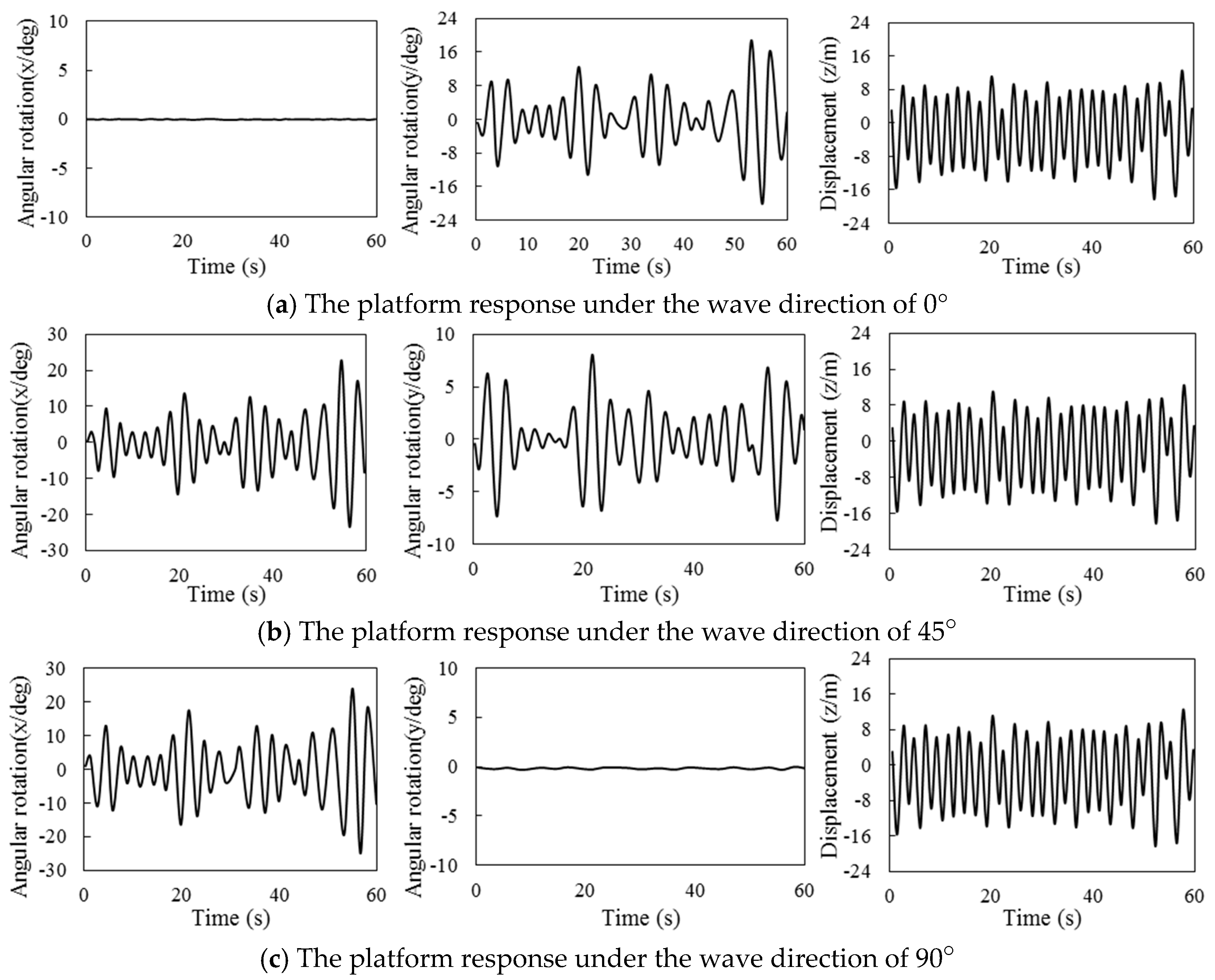
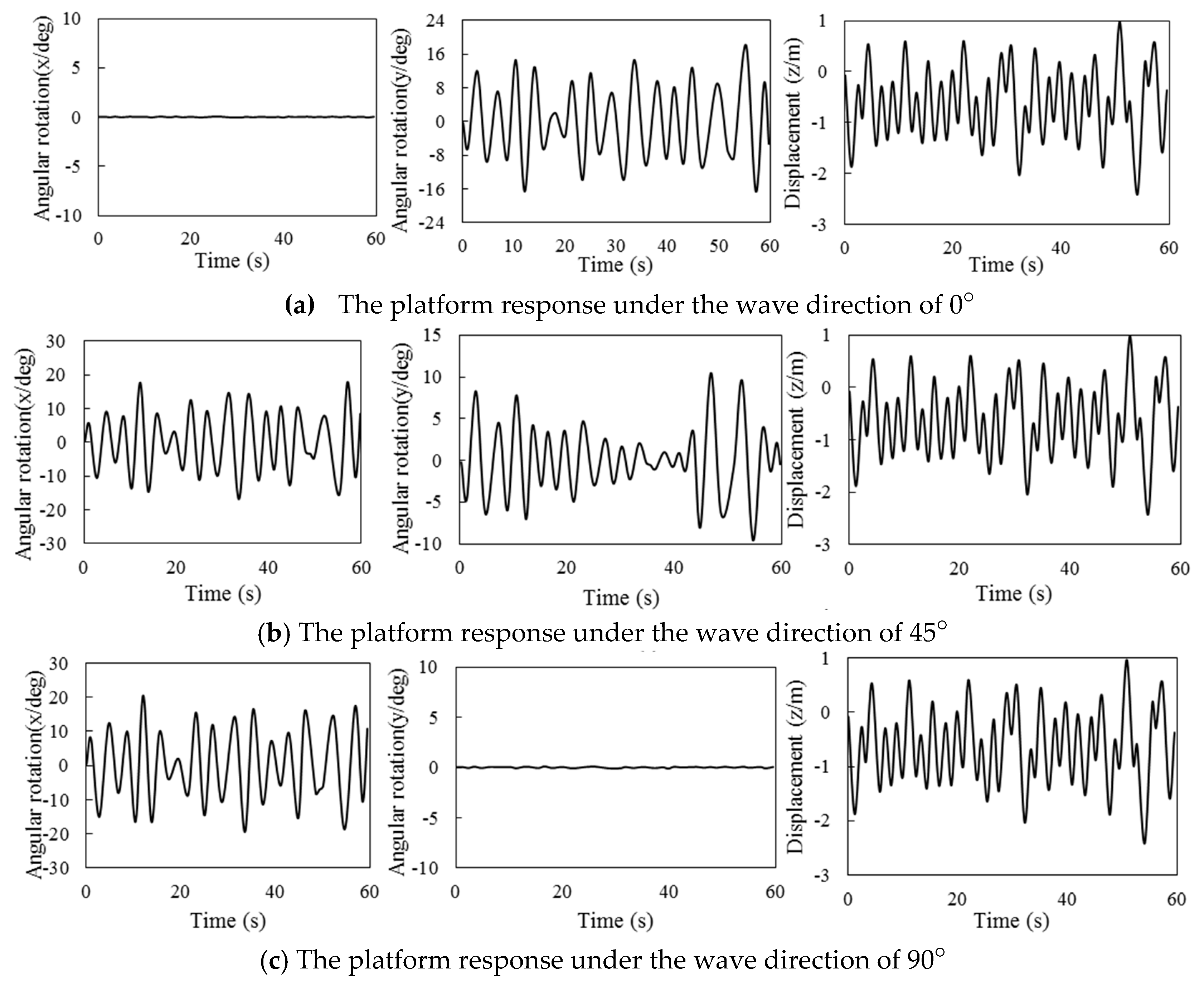
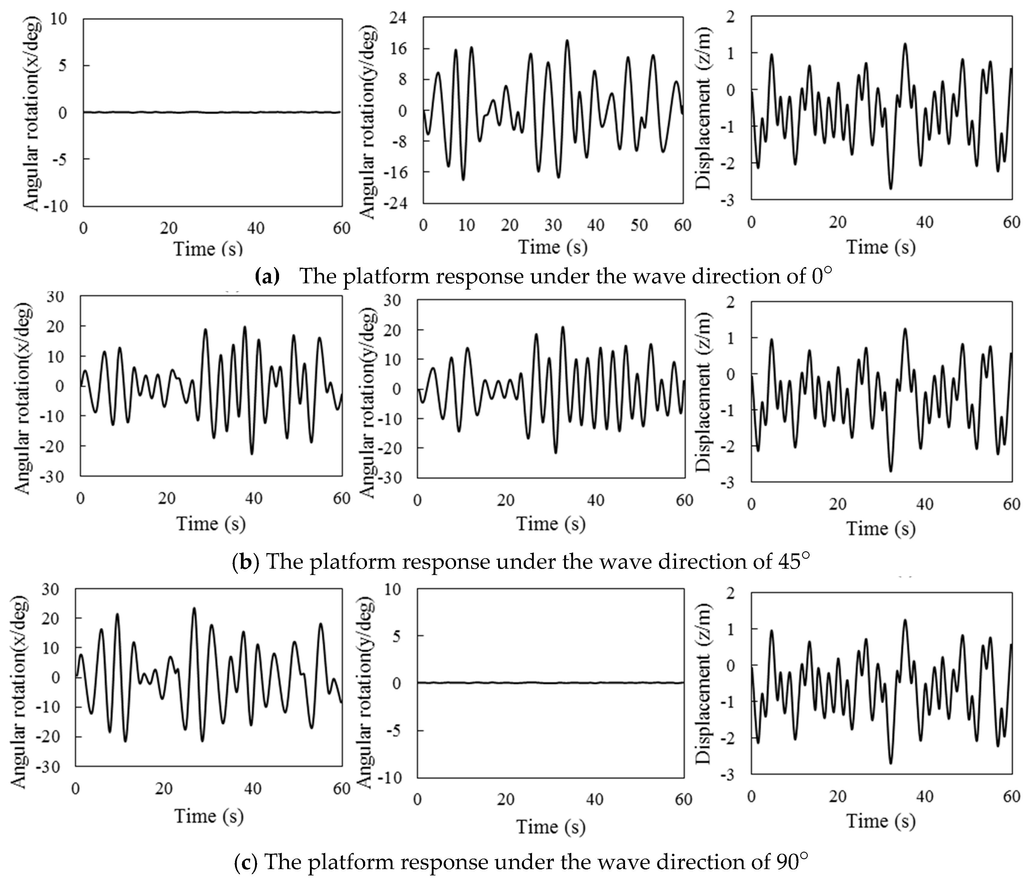
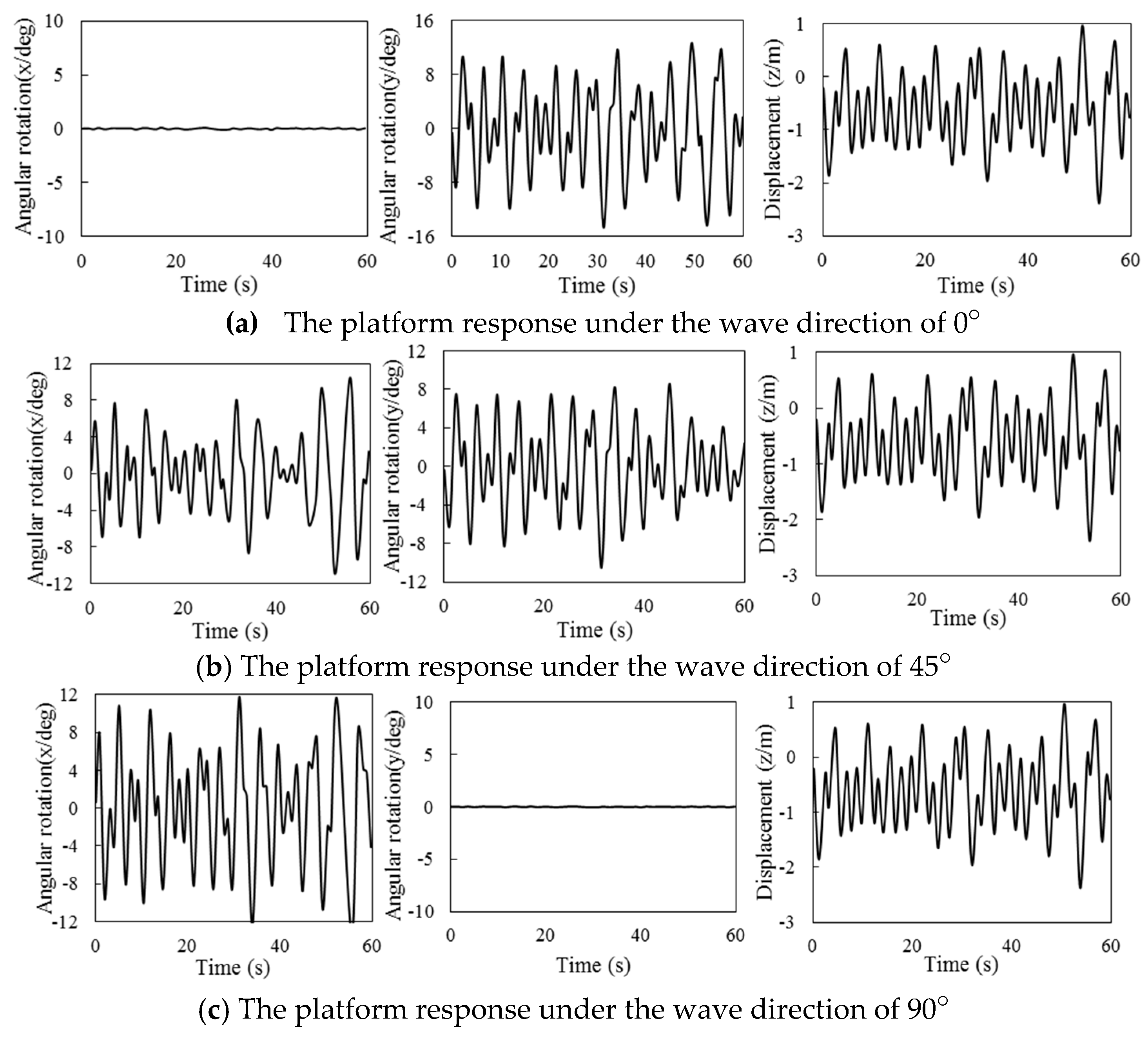
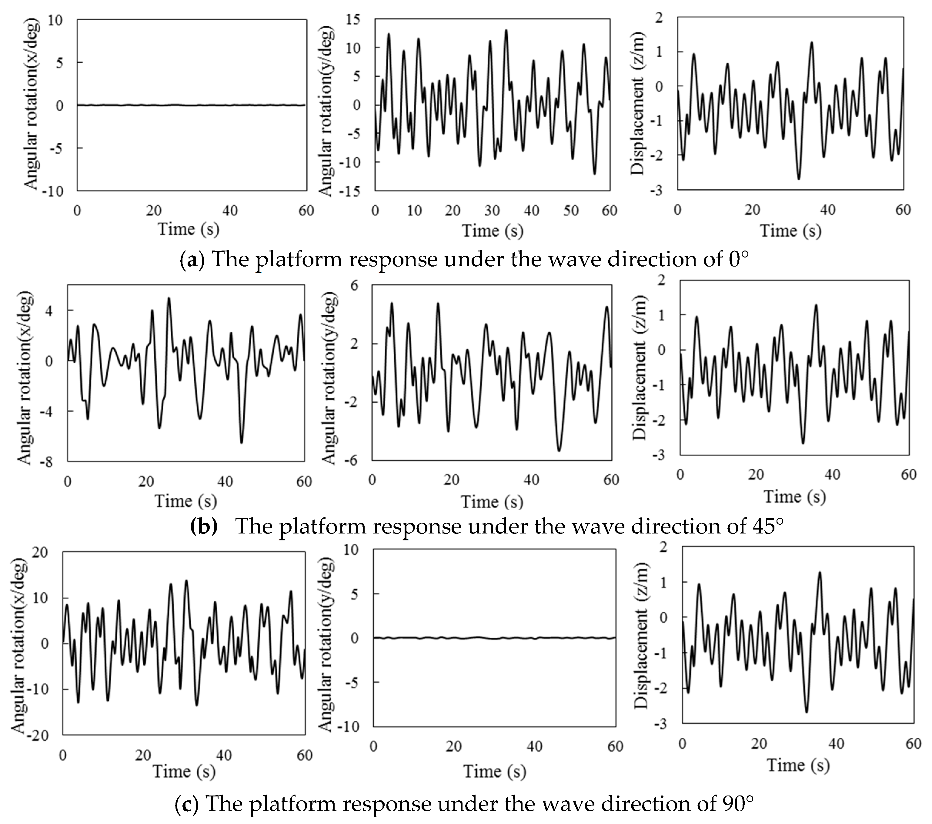
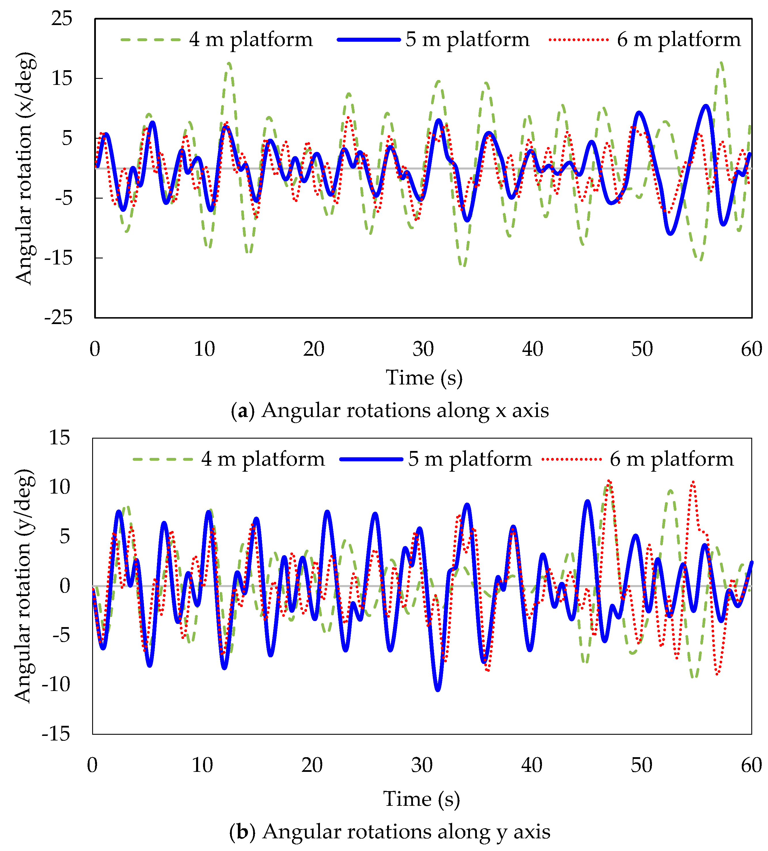
4. Simulation Results

In order to obtain the swaying situation of different sizes of the airbag, three airbag lengths are selected, namely, four meters, five meters, and six meters, which is mainly decided by enough buoyancy provided by the airbag and the small sway angle of 15 degrees induced by the sea wave under a level 3 sea state. According to the working environment of the weapon system, three sea conditions (wind-sea scale 3, 4, and 5) are selected. The wave directions are set to 0°, 45°, and 90°, respectively, and the roll, pitch, and heave motions are the main considered sway motions, as the design described in this paper is mainly used to provide a stable platform for the aiming instrument. Therefore, most attention is paid to the swing angle induced by sea waves, and the floating platform is symmetrical and even circular in all directions. In this situation, roll, pitch, and heave are the three kinds of motion that have the greatest influence on swing angle generation. Figure 4 represents the finite element model of the floating platform. The cylindrical shell in the z axis represents the fixed support structure of the load system rigidly connected to the floating platform, and the rest represent the airbag surface model.
Figure 4 shows the finite element model of the floating platform. The simulation process is as follows: Firstly, model information and statics environment are input into the finite element multi-body fluid dynamics simulation software. Then, relevant parameters used for radiation/diffraction analysis are input for radiation/diffraction analysis. Finally, wind load, wave load, and other environmental parameters need to be input for simulation. After the post-processing stage, the final simulation results can be obtained.

4.1. Four-Meter Airbag in Different Wind-Sea Scales

Figure 5 shows the response of the floating platform with wave directions of 0°, 45°, and 90°, respectively. Figure 5a is the platform response at the wave direction of 0° (the one on the left shows the angular variation around the x axis, the middle one shows the angular variation around the y axis, and the last one shows the heave movement). Figure 5b,c shows the platform responses with the 45° and 90° wave directions, respectively. The following figures are arranged in the same way as Figure 4. Figure 5 and Figure 6 show the responses of the floating platform with wave directions of 0°, 45°, and 90°, respectively, under wind-sea scale 4 and 5, respectively.
The following results can be derived in Figure 5, Figure 6 and Figure 7. For the same wind-sea scale, under a wave direction of 0°, waves travel along the x axis, and the main motion of the platform is the pitch motion around y axis and heave motion along z axis. The average peak of the pitch angle is at about 10° and roll angle is close to 0°, with heaving motion near the mass center moving up and down under the wind-sea scale 3. As the wave direction increases to 45°, the rolling angle increases, with the average peak reaching 10° and the pitch angle peak decreasing to 5°, but the heave motion hardly changes. When the wave direction is 90°, the rolling angle is obviously larger than the pitching angle, with the average peak value close to 10°, the pitching angle close to 0°, and a relatively stable heave motion. It can be seen that the motion of the platform under the 45° wave direction is the joint action of roll, pitch, and heave, while the platform under 0° or 90° wave is the joint action of pitch (or roll) and heave motion.
From Figure 5, Figure 6 and Figure 7, it also can be seen that as the wind-sea scale number increases, the peak value of the swaying angle of the platform increases. Under the wave direction of 0°, the peak of the swaying angle in wind-sea scale 4 is about 12°, and it is about 15° in wind-sea scale 5. Under a wave direction of 45°, the peak value of the swaying angle is about 15° in wind-sea scale 4 and 18° in wind-sea scale 5. Under a 90° wave direction, the peak value is about 16° in wind-sea scale 4 and about 20° in wind-sea scale 5. The mass center displacement of heave motion also shows a trend of gradual increase; the heave motion in wind-sea scale 5 shows obvious irregularity, and the fluctuation of the platform is more serious. It can be seen that the rolling, pitching, and heave motions increase with the increase in the wind-sea scale number.

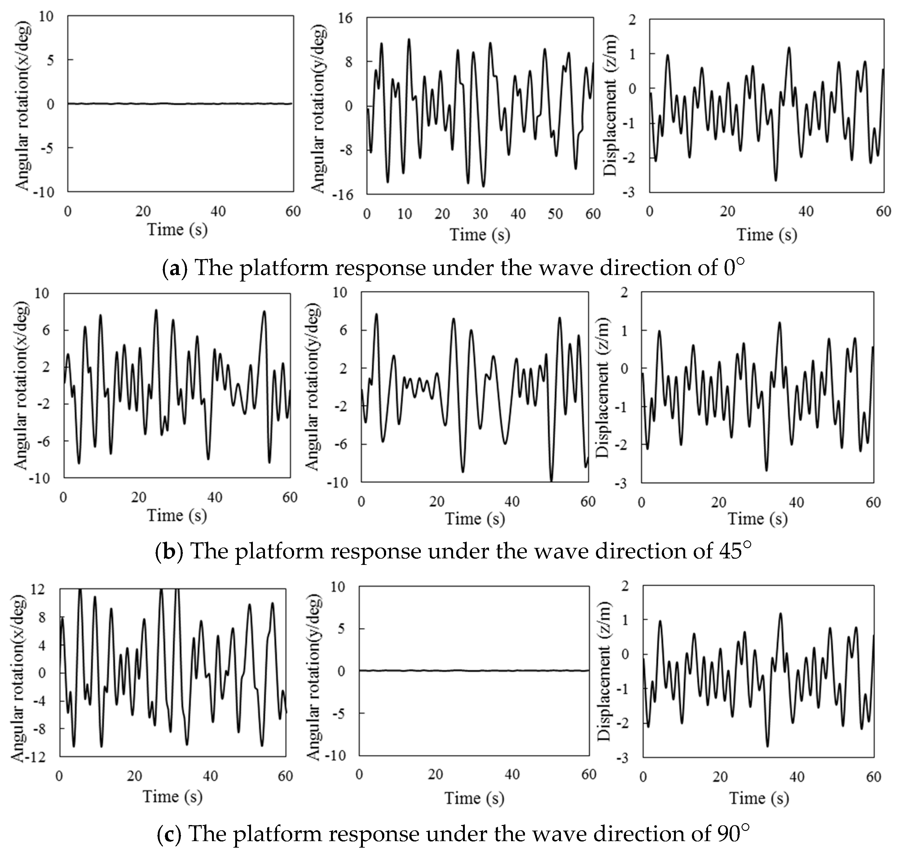
4.2. Five-Meter Airbag in Different Wind-Sea Scales

Figure 8, Figure 9 and Figure 10 show the response of the floating platform with a five-meter airbag, at 0°, 45°, and 90° wave directions under wind-sea scales 3–5, respectively. It can be seen that the platform motion with a five-meter airbag in the same sea condition is similar to that of the four-meter airbag, but the swaying angle obviously decreases. At 0° wave direction, the average peak value of the swaying angle is about 6°, 10°, and 12°, under the sea conditions of wind-sea scale 3, 4, and 5, respectively. When the wave direction is 45°, the peak value of the swaying angle is about 5°, 5°, and 8°, under the wind-sea scale 3, 4, and 5, respectively. At 90° wave direction, it is about 5°, 10°, and 12°, under the wind-sea scale 3, 4, and 5, respectively. The displacement of the mass center in heave motion has only little change compared with that of the four-meter airbag.

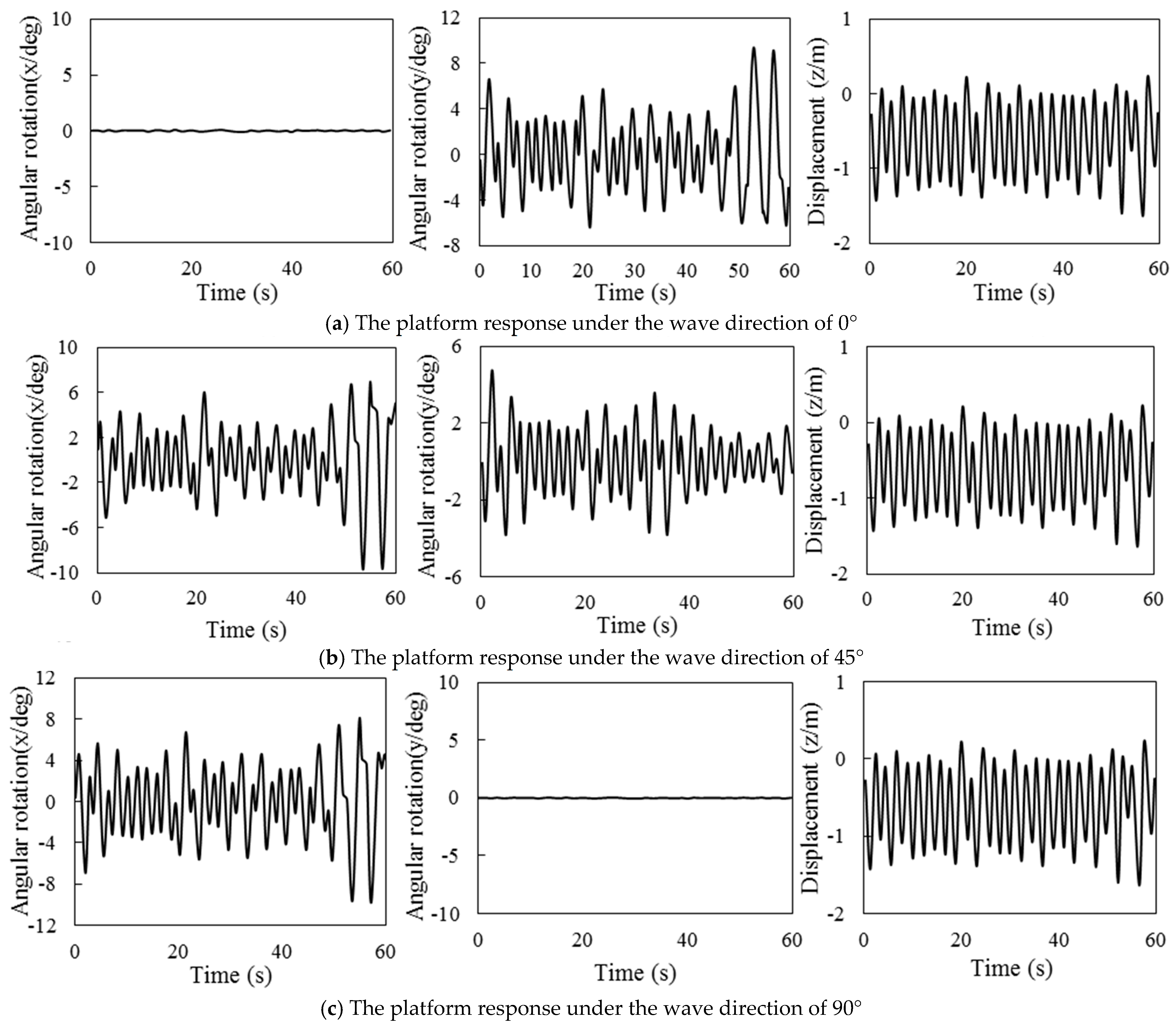
4.3. Six-Meter Airbags in Different Wind-Sea Scales

Figure 11, Figure 12 and Figure 13 are the response of the platform at wave directions of 0°, 45°, and 90°, respectively, under the conditions of wind-sea scale 3–5, respectively. As can be seen from Figure 11, Figure 12 and Figure 13, if the airbag length continues to increase, the swaying and heave degrees at all wind-sea scale conditions decrease correspondingly. The average peak value of the swaying angle of each wave is about 5° under wind-sea scale 3, and it is 8° and 10° for wind-sea scale 4 and 5, respectively.

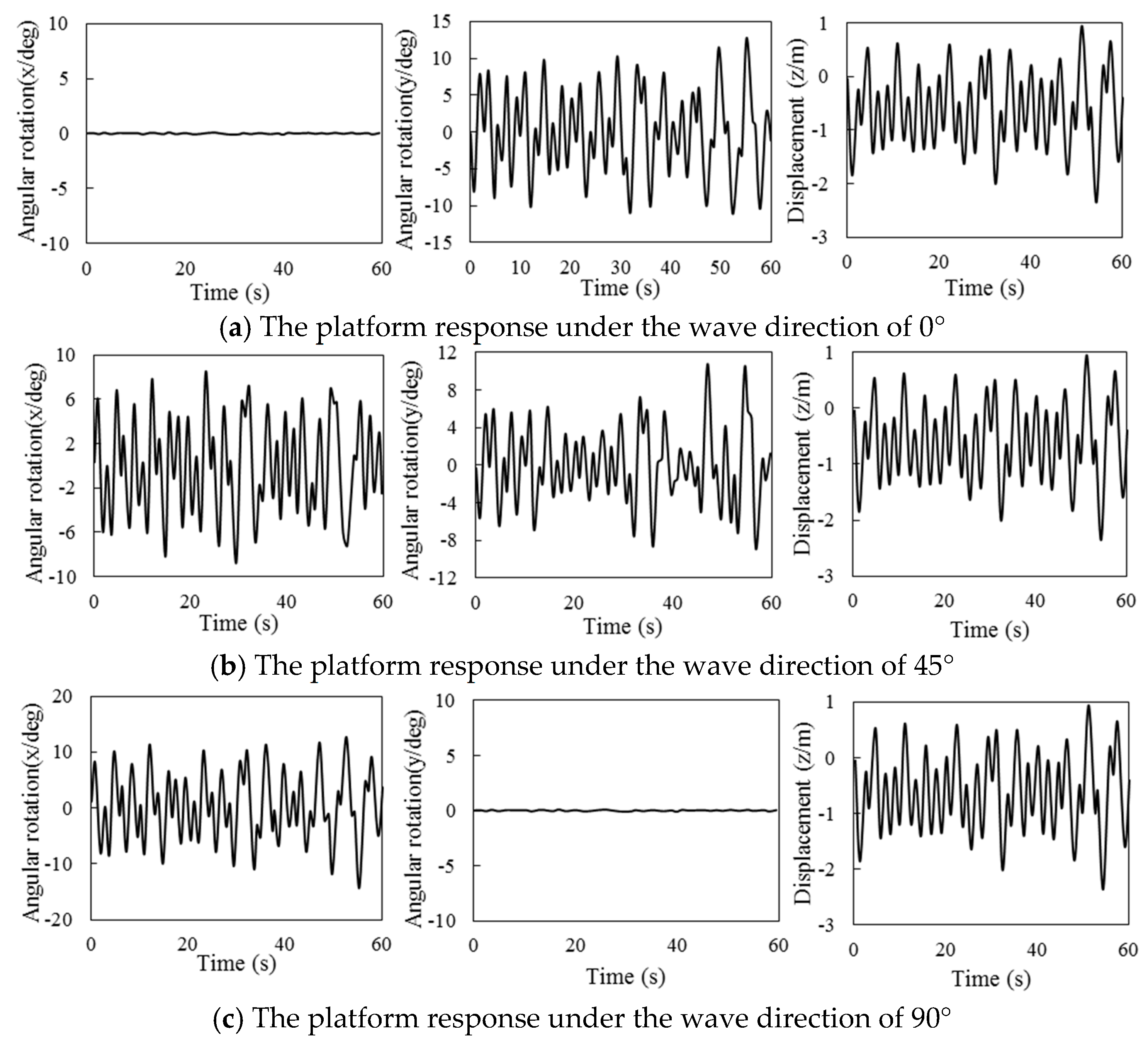
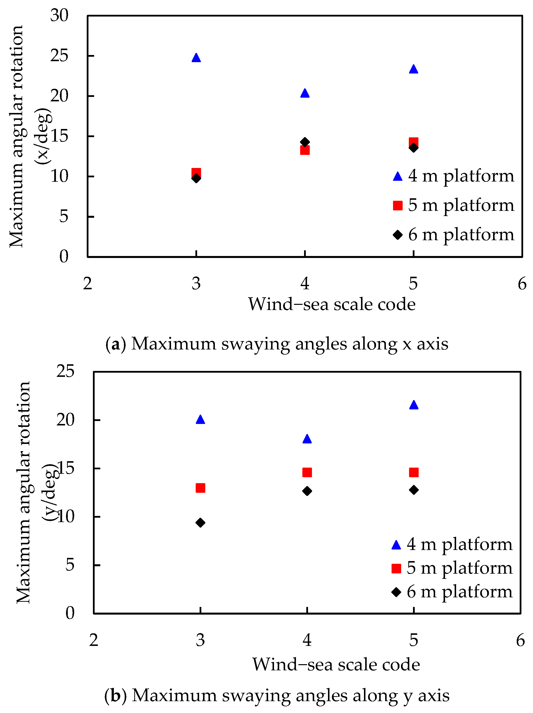
4.4. Result Discussion
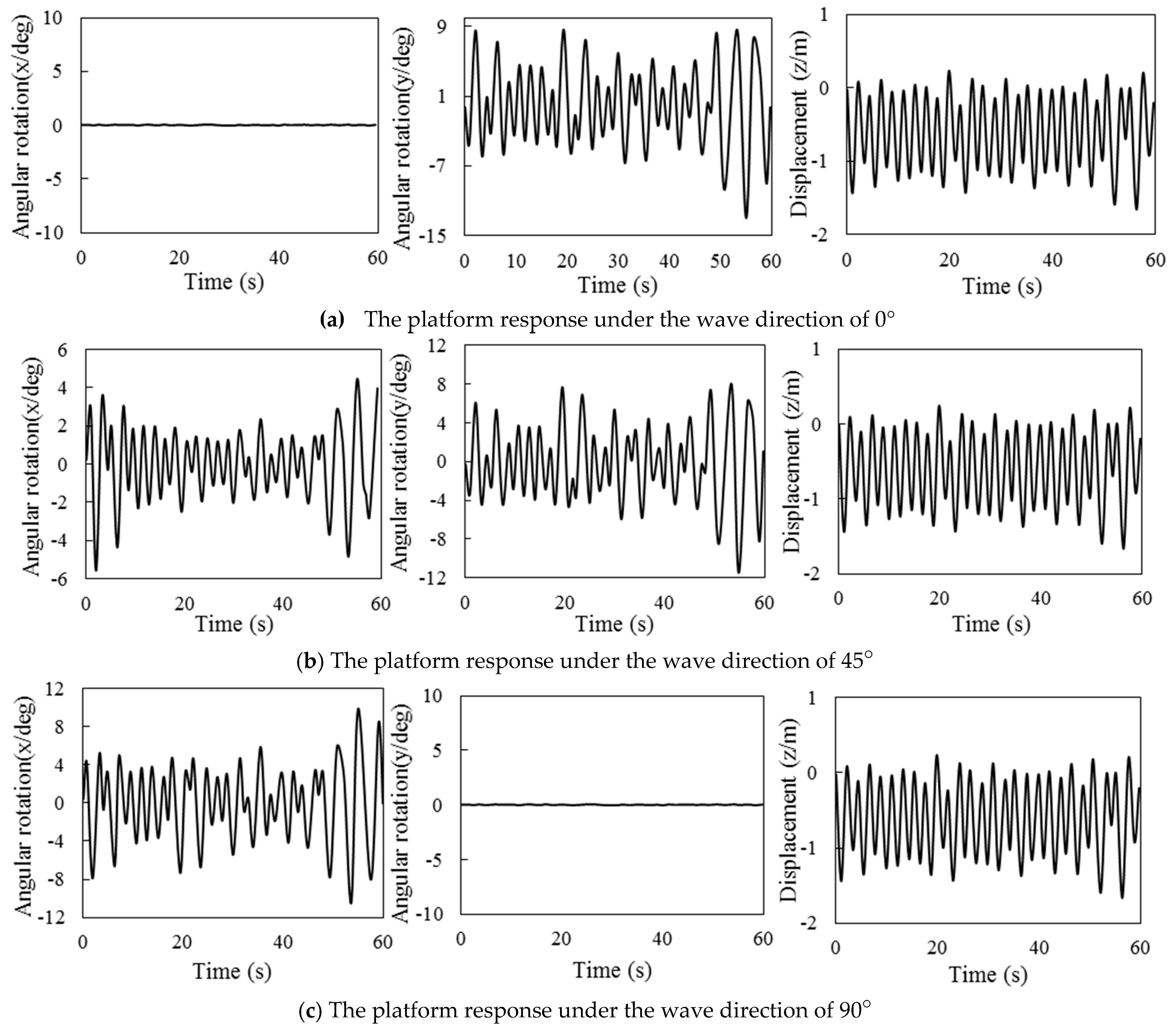
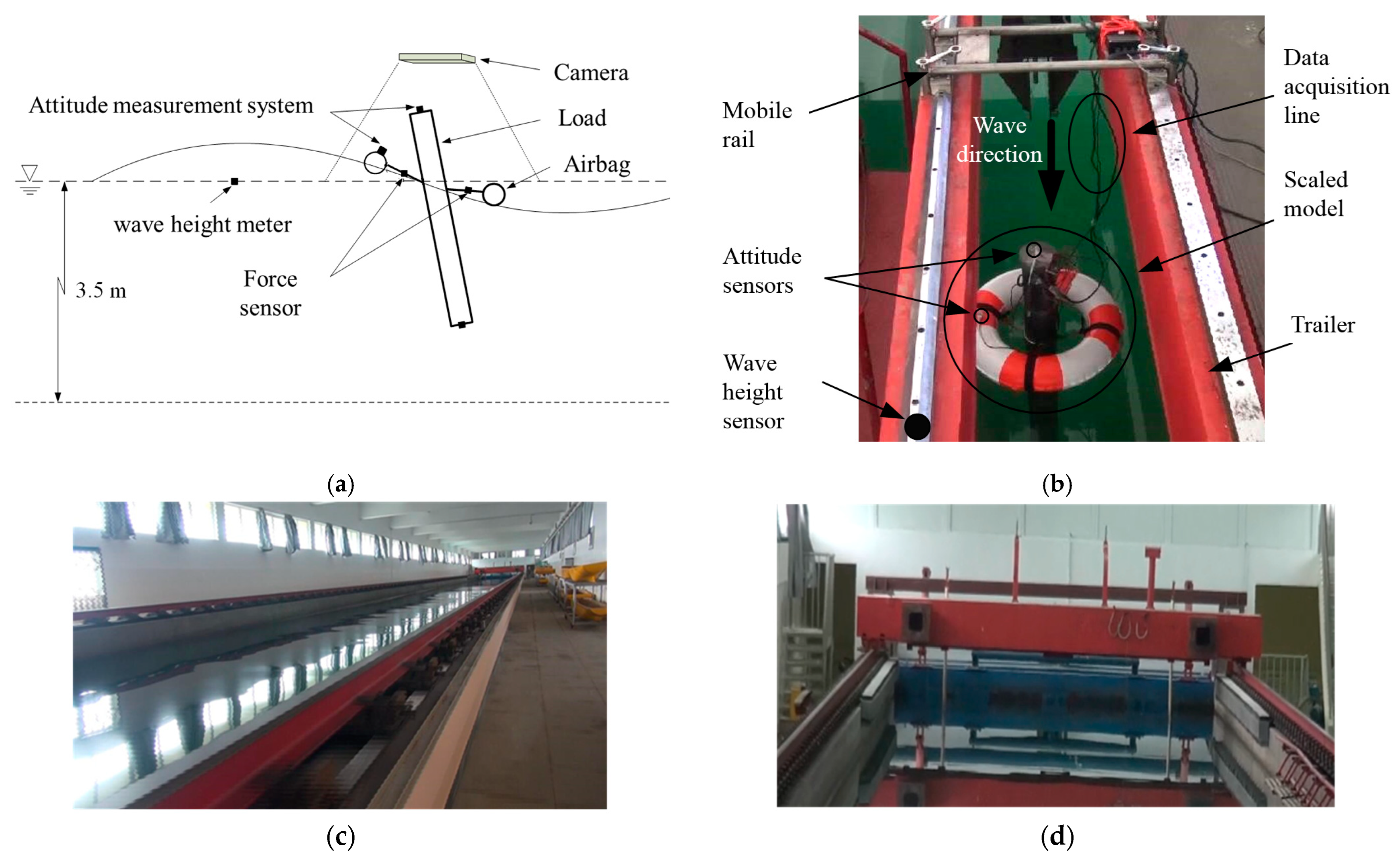
The effect of different airbag lengths on the swaying angle is investigated via comparing platform rotations under the same working conditions. Taking the wave direction of 45° as an example, angular rotations along x and y axis are compared as shown in Figure 14. It shows that increasing the length of the airbag can effectively reduce the swaying angle of the platform, but there is no significant change between a 5 m platform and a 6 m platform.
Figure 15 gives the maximum swaying angles of different size platforms in various sea conditions (up to wind-sea scale 5) during simulations. It shows that the maximum swaying angle of the 4 m platform obviously outnumbers 15°in all wind-sea scales, while the other two are within ±15° in all situations. In addition, the platform shows the tendency of automatically returning to the equilibrium position during swaying movement.
Based on the simulation results, and considering that the increment of airbag length can result in an increase in the overall mass and its inflation time, it is reasonable to select an airbag with a length of five meters.

5. Test Results

5.1. Experimental Setup

A preliminary floating test was carried out by using a scaled model in a sea wave simulating tank. The scaled model was produced based on the Froude and Strouhal theory. In this experiment, the model needs to meet the following three similarity criteria, which are geometric similarity, kinematic similarity, and dynamic similarity, respectively. It is very difficult to ensure the similarity of all dynamic conditions between the ship or ocean engineering structure and the scaled model. Since the viscous force plays a non-important role in the model experiment, the influence of viscosity is usually not considered, and only the two principles of gravitational similarity and inertia force similarity are guaranteed, which are the Froude and Strouhal numbers between the real-size structure and the scaled model and are kept equal, following the Equation (40).
F r = V m g L m = V s g L s ,   S t = V m T m L m = V s T s L s ,
where Fr represents Froude number, St represents Stohar number, and V, L, and T, respectively, represent characteristic physical quantities corresponding to velocity, line scale, and period. m represents the model and S is the entity.
After the reduction, the height of the main body of the model is 1.75 m, with a diameter of 0.125 m, and a mass of 21.875 kg with a center mass of 0.54 m. The diameter of the floating sac is 0.59 m.
The scale model experiment was carried out in the towing tank of the Key Laboratory of Ocean Engineering Technology, Zhejiang Ocean University. The towing tank and wave generator are shown in Figure 16c,d. The tank is 130 m long, 6 m wide, and 4 m deep. The front end of the tank is a hydraulic plate wave generation machine, which can produce unidirectional regular and irregular waves. The generated wave height is 0 to 0.35 m, with a period of 0.5 to 5 s. A clipping device is installed at the back end to absorb wave energy to prevent wave reflection from affecting the platform response. The schematic diagram of the scaled model experiment layout of the floating platform is shown in Figure 16a,b. The experiment model is arranged symmetrically in the tank 25 m away from the wave generator, where the waves from the wave-maker are stable. The scaled model in the tank is a rootless system on the water surface, and displacement along the wave direction will be generated under the action of waves. Therefore, the scaled model and the data acquisition lines are connected with the mobile guide, which can slide with the experimental model. The roll angle response of the floating platform is collected via the attitude measurement system, with an acquisition frequency of 100 Hz. In addition, a wave height meter used to measure the wave height and frequency generated by the wave maker, a tension sensor used to measure the change of elastic force between the floating sac and the connecting part of the platform during the movement of the floating platform, and a pressure sensor used to measure the change of water pressure at the bottom of the floating platform in the process of movement were also employed in the experiment.
The marine environment for the floating platform is level 3 wind-sea scale, and the design parameters of the experimental conditions corresponding to the scaled model are shown in Table 2. Regular waves were applied in all experiments, and each experiment was repeated three times.

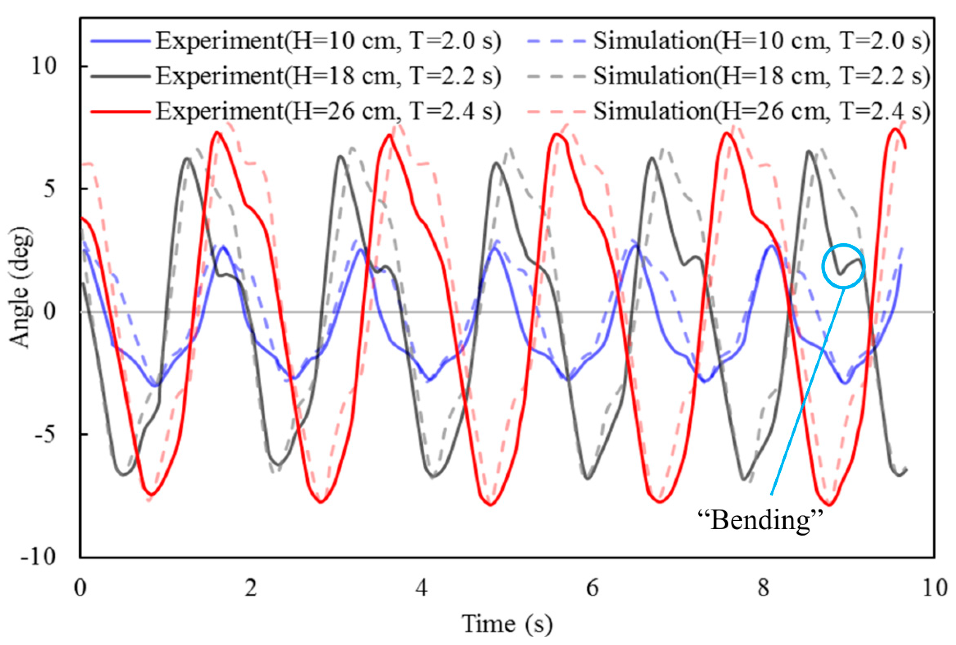
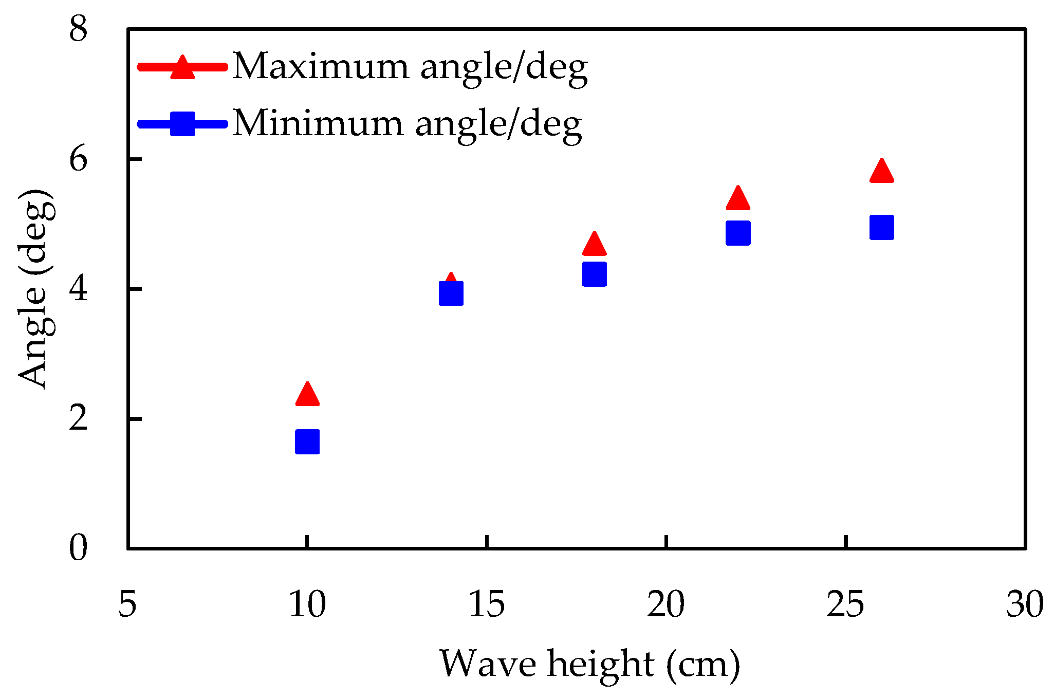
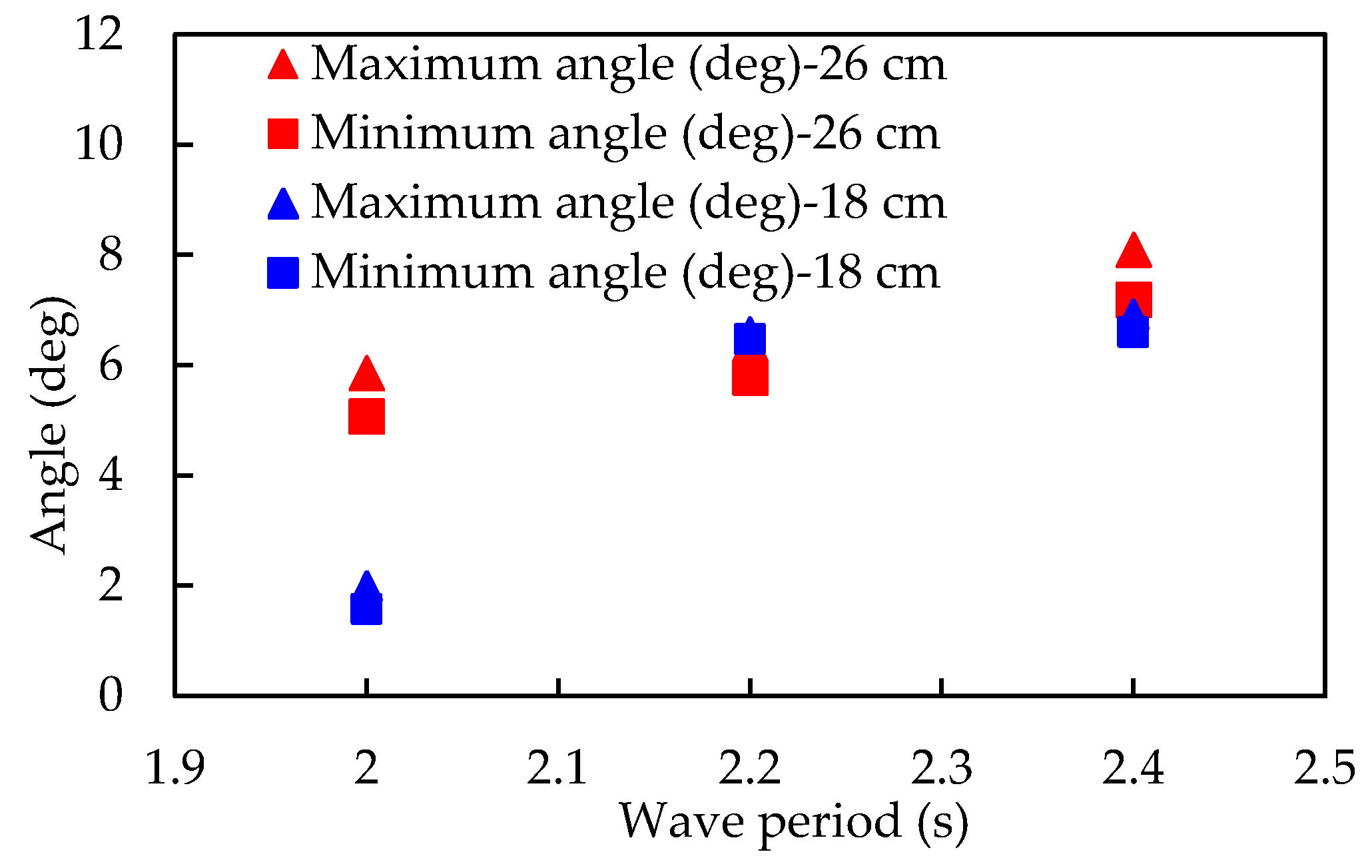
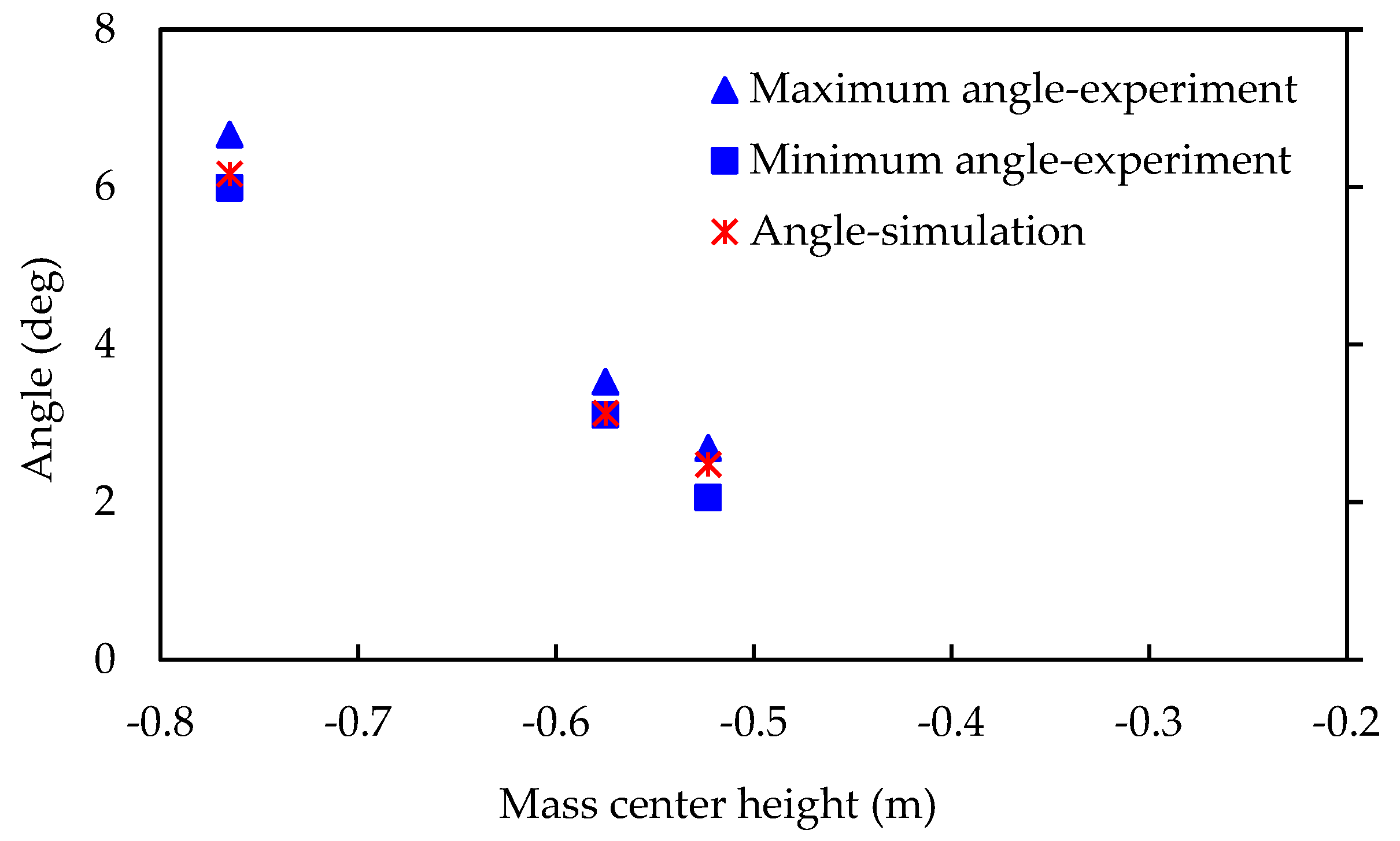
5.2. Test Results Analysis

The effects of the following system parameters, including the center of mass, the radius of the floating platform, the wave height, and the period of the wave, were studied. Figure 17 shows the comparison of the angle response of the floating platform under different wave conditions.
As shown in Figure 17, the experimental results agree well with the numerical simulation, and the angle of the platform is obviously related to the wave height and period. During all the periods, there is a typical “bending” phenomenon (denoted in Figure 16) in the experimental and simulation results, where shows some difference between the two results. This is because the airbag has a certain elasticity, which causes the delay of the angle response.
The angle response of the floating platform under different wave heights and periods was tested, and the results are shown in Figure 18 and Figure 19. Figure 18 shows that wave height has a significant influence on the platform angle. The maximum angle increases from around 2.4° to 5.8° when the wave height is changed from 10 cm to 26 cm. In Figure 19, the period change also shows its influence on the angle response. The maximum angle under 18 cm wave height increases by 5° when the wave period increases from 2 s to 2.4 s, and it is 2.3° for the situation of a 26 cm wave height.
The effect of two parameters, mass center and airbag radius, were investigated in the scaled model experiment to verify the design, the results of which are shown in Figure 20 and Figure 21. Figure 20 indicates that the maximum angle decreases with the increase in the position of the center of mass. The maximum angle decreases as the radius of the floating airbag decreases, as shown in Figure 21. Therefore, appropriate system mass center and platform radius can reduce the maximum sway angle of the system.
The results show that the floating platform design will meet the requirements of the design. In all working conditions of wind-sea scale 3, the swaying angle of the platform is within ±15°.

5.3. Stabilization Experiment in a Water Tank

In order to verify the auto-leveling performance of the floating platform in free deep water, a simulated test of the floating platform was carried out in an experimental water tank with a length and width of 6 m and a depth of 3 m, located in the underwater laboratory of Nanjing University of Science and Technology. Before the experiment, the floating platform was sealed and waterproofed. The floating capsule of the floating platform adopts a parallel floating capsule which is convenient for the experiment and can meet the requirements, connected with the floating platform by a nylon rope which is used for producing wave disturbance. The designed surface floating platform is shown in Figure 22.
The surface wave disturbance is exerted by the disturbance rope on both sides of the platform and the disturbance is generated manually via repeatedly pulling the rope. After the system is started, the slosh angle of about 0.4 Hz and ±10° is manually created, respectively. The obtained attitude stability curve is shown in Figure 23.
As can be seen from Figure 23, under the conditions of ±10 ° and 0.5 Hz of simulated sea wave disturbance, the platform can stabilize itself within the range of ±0.36 °. The result shows that the attitude stabilization system can achieve the dynamic stability of the water surface of the load system and meet the design requirements.

6. Conclusions

In this paper, an offshore unmanned auto-leveling sea-surface drifting platform is proposed. The mechanical structure, control system hardware, and software of the principle prototype are introduced. The motion equations of the floating platform are established according to the ship motion theory, and the movement of the floating platform under different wind-sea scales is simulated and analysed via multi-body fluid dynamics analysis software. The simulation results show that the proper length size of the airbag is five meters. A scaled model experiment was conducted and compared with simulation results to verify the theoretical model. A verification experiment was also conducted in a water tank for the performance of the platform via simulation of the wave disturbance. The results show that the designed floating platform could provide a stable platform in the horizontal direction under a wind-sea scale 3 environment for the defense weapon system, which well meets the design requirement. Experimental results show that the auto-leveling system can achieve a real-time leveling against the angle deviation induced by waves, with a leveling accuracy of 0.2° in a simulated wave with the angle of 12°, which well meets the requirements of observation equipment.

Author Contributions

Conceptualization, Z.M. and J.L.; Formal analysis, K.X. and F.Z.; Funding acquisition, Y.L.; Investigation, Z.M. and K.X.; Methodology, F.Z. and K.X.; Resources, J.L.; Software, Z.M.; Writing—original draft, Z.M. and K.X.; Writing—review and editing, J.L. and Y.L. All authors have read and agreed to the published version of the manuscript.

Funding

The research was supported by the Project of Sanya Yazhou Bay Science and Technology City, (No: SKJC-2022-PTDX-005) and the Research Startup Funding from Hainan Institute of Zhejiang University (NO. 0208-660202-10102080003).

Institutional Review Board Statement

Not applicable.

Informed Consent Statement

Not applicable.

Data Availability Statement

The data presented in this study are available on request from the corresponding author.

Conflicts of Interest

The authors declare no conflict of interest.

References

  1. Li, Q.A.; Maeda, T.; Kamada, Y.; Murata, J.; Kawabata, T.; Furukawa, K. Analysis of Aerodynamic Load on Straight-bladed Vertical Axis Wind Turbine. J. Therm. Sci. 2014, 23, 315–324. [Google Scholar] [CrossRef]
  2. Zhao, H.; Wu, Q.; Hu, S.; Xu, H.; Rasmussen, C.N. Review of energy storage system for wind power integration support. Appl. Energy 2015, 137, 545–553. [Google Scholar] [CrossRef]
  3. Borg, M.; Collu, M. Frequency-domain characteristics of aerodynamic loads of offshore floating vertical axis wind turbines. Appl. Energy 2015, 155, 629–636. [Google Scholar] [CrossRef]
  4. Gueydon, S.; Wuillaume, P.; Jonkman, J.; Robertson, A.; Platt, A. Comparison of Second-Order Loads on a Tension-Leg Platform for Wind Turbines (No. NREL/CP-5000-63840); National Renewable Energy Lab.(NREL): Golden, CO, USA, 2015.
  5. Bredmose, H.; Lemmer, F.; Borg, M.; Pegalajar-Jurado, A.; Mikkelsen, R.F.; Larsen, T.S.; Fjelstrup, T.; Yu, W.; Lomholt, A.K.; Boehm, L.; et al. The Triple Spar campaign: Model tests of a 10MW floating wind turbine with waves, wind and pitch control. Energy Procedia 2017, 137, 58–76. [Google Scholar] [CrossRef] [Green Version]
  6. Greco, M.; Lugni, C.; Faltinsen, O.M. Influence of motion coupling and nonlinear effects on parametric roll for a floating production storage and offloading platform. Philos. Trans. A Math. Phys. Eng. Sci. 2015, 373, 20140110. [Google Scholar] [CrossRef]
  7. Chen, Y.; Ye, J.; Zhang, X.; Liang, F. Experimental study on predictive control of stable platform system of shipborne helicopter. J. Dalian Marit. Univ. 2010, 36, 77–80. [Google Scholar]
  8. Cordle, A.; Jonkman, J. State of the Art in Floating Wind Turbine Design Tools (No. NREL/CP-5000-50543); National Renewable Energy Lab.(NREL): Golden, CO, USA, 2011.
  9. Tran, T.-T.; Kim, D.-H. The platform pitching motion of floating offshore wind turbine: A preliminary unsteady aerodynamic analysis. J. Wind. Eng. Ind. Aerodyn. 2015, 142, 65–81. [Google Scholar] [CrossRef] [Green Version]
  10. Chakrabarti, S. Handbook of Offshore Engineering (2-Volume Set); Elsevier: Amsterdam, The Netherlands, 2005. [Google Scholar]
  11. Hilkert, J. Inertially stabilized platform technology concepts and principles. IEEE Control Syst. Mag. 2008, 28, 26–46. [Google Scholar]
  12. Li, H.W.; Xu, Z.D.; Wang, F.; Gai, P.P.; Gomez, D.; Dyke, S.J. Development and Validation of a Nonlinear Model to Describe the Tension–Compression Behavior of Rubber-Like Base Isolators. J. Eng. Mech. 2023, 149, 04022104. [Google Scholar] [CrossRef]
  13. Li, Q.Q.; Xu, Z.D.; Dong, Y.R.; He, Z.H.; He, J.X.; Yan, X. Hyperelastic Hybrid Molecular Chain Model of Thermal-Oxidative Aging Viscoelastic Damping Materials Based on Physical–Chemical Process. J. Eng. Mech. 2023, 149, 04022099. [Google Scholar] [CrossRef]
  14. Dai, J.; Xu, Z.D.; Gai, P.P.; Hu, Z.W. Optimal design of tuned mass damper inerter with a Maxwell element for mitigating the vortex-induced vibration in bridges. Mech. Syst. Signal Process. 2021, 148, 107180. [Google Scholar] [CrossRef]
  15. Xu, Z.D.; Yang, Y.; Miao, A.N. Dynamic analysis and parameter optimization of pipelines with multidimensional vibration isolation and mitigation device. J. Pipeline Syst. Eng. Pract. 2021, 12, 04020058. [Google Scholar] [CrossRef]
  16. Yingzhong Liu, G.L. The Theory of Motion of a Ship on Waves, 1st ed.; Shanghai Jiao Tong University Press: Shanghai, China, 1987. [Google Scholar]
  17. Korvin-Kroukovsky, B.V.; Jacobs, W.R. Pitching and Heaving Motions of a Ship in Regular Waves; Experimental Towing TANK: Hoboken, NJ, USA; Stevens Institute of Technology: Hoboken, NJ, USA, 1957; Volume 659. [Google Scholar]
  18. Wang, L.; Wu, Q.; Liu, J.; Li, S.; Negenborn, R.R. State-of-the-art research on motion control of maritime autonomous surface ships. J. Mar. Sci. Eng. 2019, 7, 438. [Google Scholar] [CrossRef] [Green Version]
  19. Yang, Y.-S. Review on ship motion control. J. Traffic Transp. Eng. 2003, 3, 34–39. [Google Scholar]
  20. Kim, Y.; Shin, Y.S.; Lin, W.M.; Yue, D.K.P. September. Study on sloshing problem coupled with ship motion in waves. In Proceedings of the 8th International Conference on Numerical Ship Hydrodynamics, Busan, Republic of Korea, 22–25 September 2003. [Google Scholar]
  21. Bishop RE, D.; Price, W.G. An investigation into the linear theory of ship response to waves. J. Sound Vib. 1979, 62, 353–363. [Google Scholar] [CrossRef]
  22. Crippa, G.; Nobili, C.; Seis, C.; Spirito, S. Eulerian and Lagrangian Solutions to the Continuity and Euler Equations with L^1 Vorticity. SIAM J. Math. Anal. 2017, 49, 3973–3998. [Google Scholar] [CrossRef] [Green Version]
  23. Martelli, M.; Viviani, M.; Altosole, M.; Figari, M.; Vignolo, S. Numerical modelling of propulsion, control and ship motions in 6 degrees of freedom. Proc. Inst. Mech. Eng. Part M J. Eng. Marit. Environ. 2014, 228, 373–397. [Google Scholar] [CrossRef]
  24. Benetazzo, A. Accurate measurement of six degree of freedom small-scale ship motion through analysis of one camera images. Ocean. Eng. 2011, 38, 1755–1762. [Google Scholar] [CrossRef]
  25. Lee, S.; You, J.M.; Lee, H.H.; Lim, T.; Park, S.T.; Seo, J.; Rhee, K.P. Experimental study on the six degree-of-freedom motions of a damaged ship floating in regular waves. IEEE J. Ocean. Eng. 2015, 41, 40–49. [Google Scholar]
  26. Suzuki, R.; Ueno, M.; Tsukada, Y. Numerical simulation of 6-degrees-of-freedom motions for a manoeuvring ship in regular waves. Appl. Ocean. Res. 2021, 113, 102732. [Google Scholar] [CrossRef]
  27. Zhang, X.; Yin, Y.; Jin, Y. 6-DOF mathematical model of ship motion in regular waves. J. Traffic Transp. Eng. 2007, 7, 4. [Google Scholar]
  28. Mousaviraad, S.M.; Carrica, P.M.; Stern, F. Development and validation of harmonic wave group single-run procedure for RAO with comparison to regular wave and transient wave group procedures using URANS. Ocean. Eng. 2010, 37, 653–666. [Google Scholar] [CrossRef]
  29. Gervelas, R.; Trarieux, F.; Patel, M. A time-domain simulator for an oscillating water column in irregular waves at model scale. Ocean. Eng. 2011, 38, 1007–1013. [Google Scholar] [CrossRef]
Figure 1. Structure diagram of the surface unmanned drifting platform.
Jmse 11 00278 g001
Figure 2. Structure diagram of the floating platform.
Jmse 11 00278 g002
Figure 3. The coordinate system setting of the floating platform.
Jmse 11 00278 g003
Figure 4. Finite element model of floating platform.
Jmse 11 00278 g004
Figure 5. The platform response under wind−sea scale 3 with different wave directions.
Jmse 11 00278 g005
Figure 6. The platform response under wind−sea scale 4 with different wave directions.
Jmse 11 00278 g006
Figure 7. The platform response under wind−sea scale 5 with different wave directions.
Jmse 11 00278 g007
Figure 8. The platform response under wind−sea scale 3 with different wave directions.
Jmse 11 00278 g008
Figure 9. The platform response under wind−sea scale 4 with different wave directions.
Jmse 11 00278 g009
Figure 10. The platform response under wind−sea scale 5 with different wave directions.
Jmse 11 00278 g010
Figure 11. The platform response under wind−sea scale 3 with different wave directions.
Jmse 11 00278 g011
Figure 12. The platform response under wind−sea scale 4 with different wave directions.
Jmse 11 00278 g012
Figure 13. The platform response under wind−sea scale 5 with different wave directions.
Jmse 11 00278 g013
Figure 14. Angular rotations of different size platforms under wave direction of 45° in wind−sea scale 4.
Jmse 11 00278 g014
Figure 15. Maximum angular rotations of different size platforms under different wind−sea scales.
Jmse 11 00278 g015
Figure 16. Experiment setup for scaled model verification (a) Sketch of the experiment setup, (b) Experiment setup, (c) The towing tank, (d) The wave generator.
Jmse 11 00278 g016
Figure 17. Experimental and simulation results of the platform angle response under different wave conditions.
Jmse 11 00278 g017
Figure 18. Angle response under different wave heights at 2 s wave period.
Jmse 11 00278 g018
Figure 19. Angle response under different wave periods with wave heights of 18 cm and 26 cm.
Jmse 11 00278 g019
Figure 20. Effects of the mass center on the angular response of the platform.
Jmse 11 00278 g020
Figure 21. Effects of the airbag radius on the angular response of the platform.
Jmse 11 00278 g021
Figure 22. Floating platform setup for water surface stabilization experiment.
Jmse 11 00278 g022
Figure 23. System stability curve at ±10° periodic wave disturbance.
Jmse 11 00278 g023
Table 1. World Meteorological Organization(WMO) wind-sea scale code.
WMO Wind-Sea Scale CodeCharacteristicsWave Height (m)
0Calm (Glassy)0
1Calm (Rippled)<0.1
2Smooth (Wavelets)0.1–0.5
3Slight0.5–1.25
4Moderate1.25–2.5
5Rough2.5–4
Table 2. Parameter settings of the generated waves.
ConditionsPeriod (s)Height (cm)
1210
2214
3218
4222
5226
62.218
72.418
82.226
92.426
102.218
112.218
Disclaimer/Publisher’s Note: The statements, opinions and data contained in all publications are solely those of the individual author(s) and contributor(s) and not of MDPI and/or the editor(s). MDPI and/or the editor(s) disclaim responsibility for any injury to people or property resulting from any ideas, methods, instructions or products referred to in the content.

