Article

Enhancing Power Transmission Stability of AUV’s Wireless Power Transfer System with Compact Planar Magnetic Coupler

1
School of Electrical Engineering, Xi’an University of Technology, Xi’an 710048, China
2
School of Marine Science and Technology, Northwestern Polytechnical University, Xi’an 710072, China
3
School of Astronautics, Northwestern Polytechnical University, Xi’an 710072, China
4
School of Electrical Engineering, Xi’an Jiaotong University, Xi’an 710049, China
*
Author to whom correspondence should be addressed.
J. Mar. Sci. Eng. 2023, 11(3), 566; https://doi.org/10.3390/jmse11030566
Submission received: 13 February 2023 / Revised: 28 February 2023 / Accepted: 2 March 2023 / Published: 6 March 2023
(This article belongs to the Special Issue Frontiers in Deep-Sea Equipment and Technology II)

Abstract

:
In this paper, a wireless power transfer (WPT) system with a compact planar magnetic coupler for an autonomous underwater vehicle (AUV) is proposed. A passive induction (PI) coil is integrated into the circular transmitter (Tx) coil to build a uniform magnetic field (UMF), which can guarantee the stable output of the WPT system under uncertain radial and axial misalignments for AUV. Based on normalized magnetic induction intensity distribution analysis, a UMF constructing method with a PI coil is given, aiming to eliminate the fluctuation of magnetic field intensity, and the PI coil design principles and flow chart are obtained. The theoretical analysis shows the proposed integrated coil can effectively enhance the radial misalignment tolerance compared with a conventional circular spiral coil. The zero-phase angle (ZPA) input condition can be achieved by adjusting the series capacitor connected with the Tx coil in S-S compensation topology. Experimental results show that the proposed magnetic coupler containing an integrated coil significantly improves the stability of output power and power transfer efficiency within the possible radial and axial misalignments compared with a conventional coupler. It was demonstrated that the output power changes less than 5.5% and the power transfer efficiency maintains at approximately 84.5% in arbitrary radial positions within the possible working region with an axial transfer distance of 50 mm in saltwater.

1. Introduction

AUVs play an increasingly important role in the development and utilization of marine resources, scientific exploration, and military applications. Power supply is the key problem that restricts the long-term continuous operation of AUVs. The last decade has witnessed rapidly growing extensive research on WPT technology; recently, WPT has been widely used in electric vehicles, household appliances, and industrial devices [1]. Compared to conventional energy supplement approaches for AUVs, such as battery swapping [2] and wet-mate contact charging [3], which suffer from limited maneuverability, and insulation and worn conductor issues, WPT technology has attracted increasing attention to becoming a reliable and safe underwater charging method for AUV [4,5].
The magnetic coupler is the key component that determines the performance of a WPT system, including output power, power transfer efficiency, misalignment tolerance, and electromagnetic compatibility. Various magnetic couplers for AUVs with different structures have been studied [6,7,8,9,10,11,12,13]. A three-phase WPT system for a lightweight AUV was proposed in [6], which enhanced the system’s misalignment tolerance to rotational offsets, but the axial and radial misalignments were not considered. Wu et al. [7] developed a magnetic coupler structure with a quadruple Tx coil and crossed dipole Rx coil to prevent rotational and axial misalignment. Zeng et al. [8] proposed a novel hybrid transmitter composed of conical and planar spiral coils. The experimental results showed that the proposed WPT system’s output power changes were within 5.7%, and the power transfer efficiency was maintained at approximately 86% in an excessive misalignment area with a transfer distance of 2 cm. A magnetic coupler structure with a spiral tube type is adopted in [10] to be compatible with the structure of AUV. In addition, Wang et al. [14] aimed at proposing an omnidirectional and positioning-tolerant planar-type AUV docking and charging platform, which has no constraints on AUV structures. However, two main shortcomings restricted their application—on the one hand, some couplers are unconsolidated and space-consuming; furthermore, some magnetic couplers are incompatible with an AUV’s hull, and modifications are inevitable, which have negative effects on the hydrodynamic or pressure-resistant performance of AUVs. On the other hand, in most couplers’ design procedures, radial, axial, and rotational misalignments, which may be caused by docking errors or ocean current impact, were not taken into consideration simultaneously.
In order to guarantee AUVs obtain a stable power supply from the WPT system under uncertain misalignments, a UMF in a specified charging area should be formed. Some scholars have conducted relevant research on the construction of a UMF with a planar electromagnetic coupling coil. Wang et al. proposed a method of using a multiple-antiparallel square spiral structure transmitting coil to form a UMF [15]. In the literature [16], the geometric parameters of the anti-parallel square spiral transmitting coil were optimized by genetic algorithm, and the magnetic field uniformity factor was defined; the measurement results showed that the magnetic field uniformity factor was reduced from 0.154 to 0.089 after optimization. Zhang et al. added a compensation structure to the circular array coil, and extended the range of UMF [17]. A novel hybrid structure composed of a coil and a spiral winding was proposed for enhancing the uniform magnetic field distribution over the charging surface by Hui et al. [18]. A planar distributed multi-coil transmitter structure composed of a chief coil and booster coils to stretch the uniformity of the magnetic field was proposed in [19]. Transmitter arrays have also been proposed to build a UMF [20,21]. The above-mentioned UMF construction methods change the original coupling coil structure, resulting in variations in parameters such as self-inductance, which increases the complexity of WPT system modeling and analysis.
This paper proposes a WPT system with a compact planar magnetic coupler for an AUV. PI coil is incorporated into the circular Tx coil to generate a UMF, which enhances the radial and axial misalignment tolerance. The magnetic coupler is suitable for an AUV’s WPT system because of its compact planar structure, and modifications to the AUV’s hull are unnecessary. Additionally, the circular magnetic coupler has inherent insensitivity to rotational misalignments. Circuit analysis demonstrates that the addition of a PI coil changes the input impedance of the WPT system with S-S compensation topology. The ZPA input condition can be maintained by adjusting the value of compensation capacitor C1, which allows the WPT system to remain with high efficiency when the load changes. Theoretical analysis reveals that a PI coil improves the stability of output power; meanwhile, it brings little effect to power transfer efficiencies of less than 3%. Experimental results verify the proposed magnetic coupler’s performance in stability enhancement of output power and power transfer efficiency under different radial and axial misalignments in comparison with a conventional coupler. A comparison of some UMF construction methods and the proposed magnetic coupler of this work is obtained, as shown in Table 1.

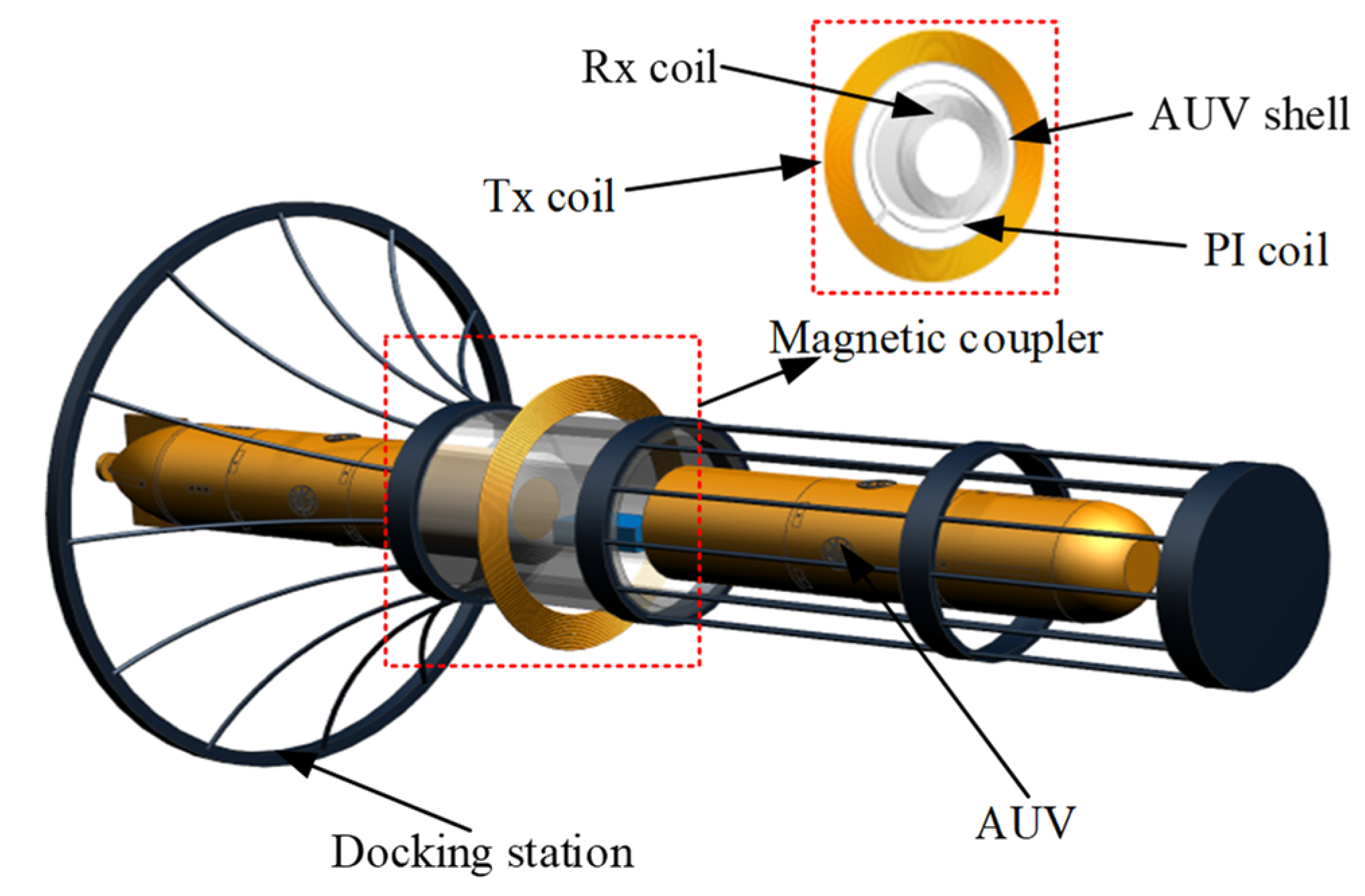
2. Magnetic Coupler Design

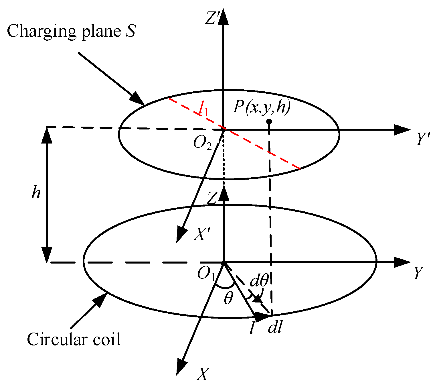
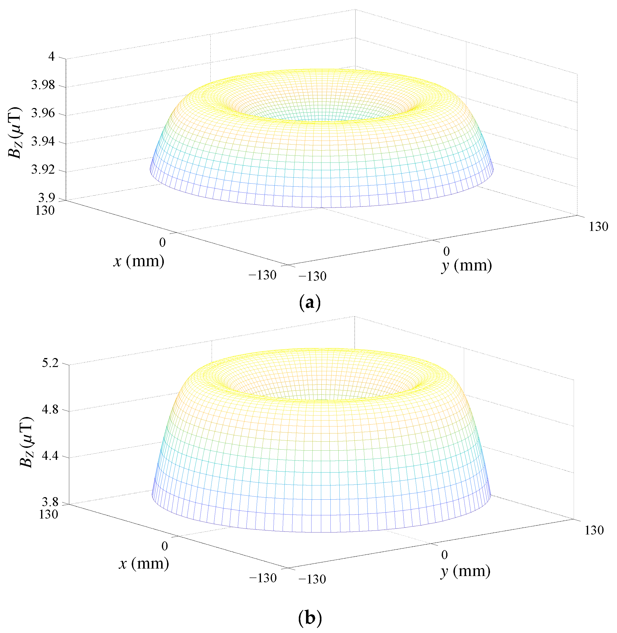
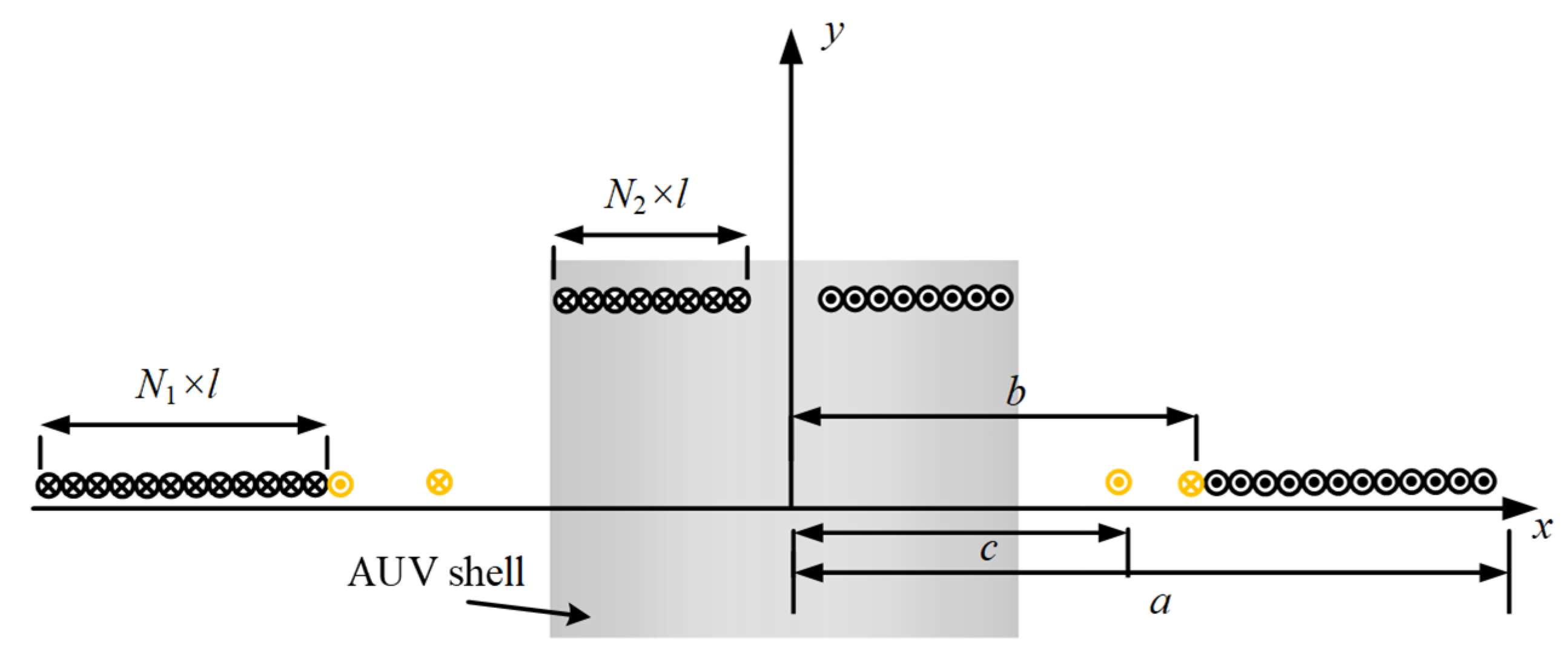
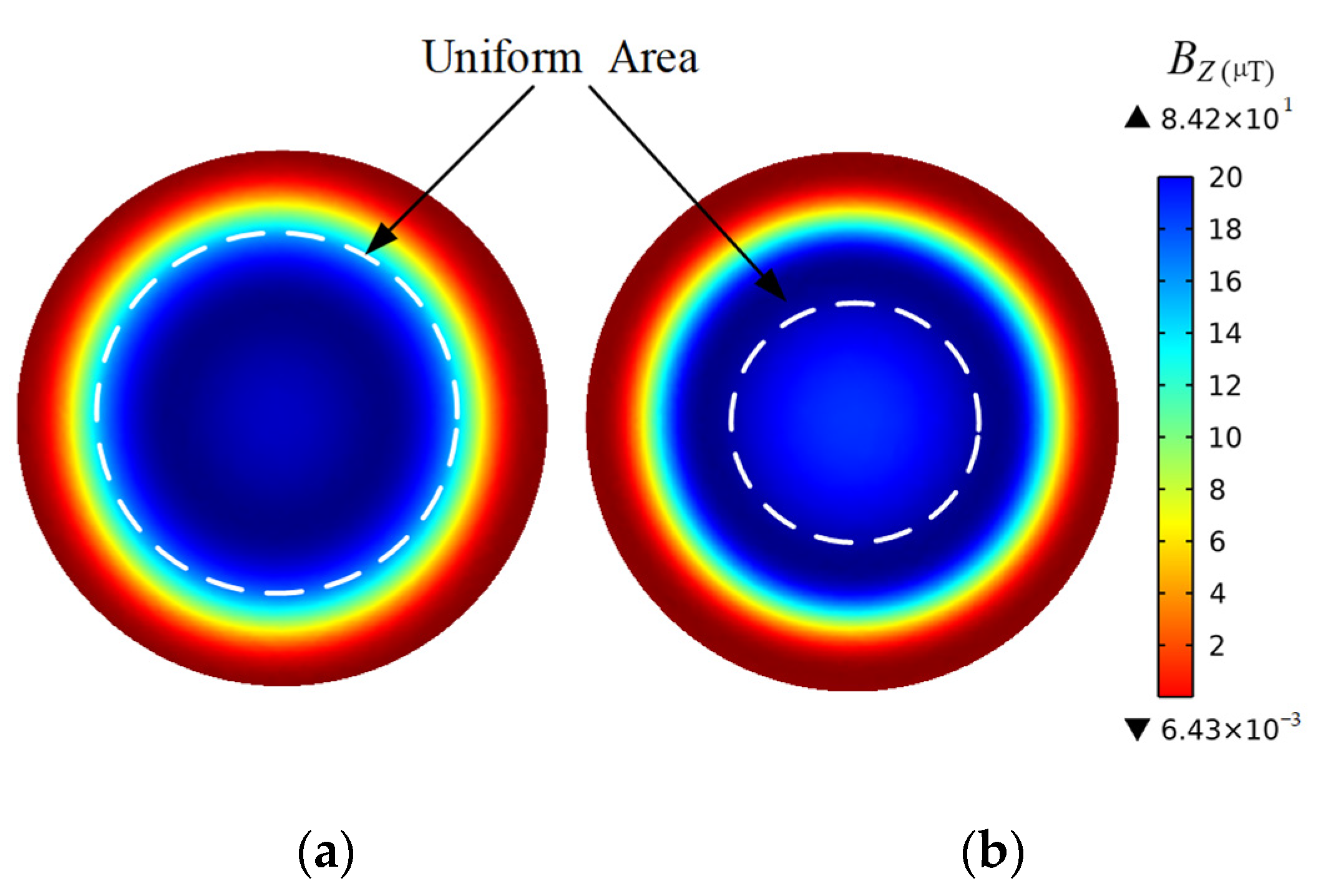
2.1. Discussion of Magnetic Field Distribution of Circular Coil

Suppose that the radius of a single-turn circular Tx coil is a; simultaneously, the receiver (Rx) coil is located in the circular charging plane S at the gap of h, and the radius of the S-plane is greater than the radius of the Rx coil, as shown in Figure 1.
Where θ is the included angle between O 1 l and the X-axis. When the Rx coil moves arbitrarily in the S-plane, the power “picked” by the Rx coil is determined by the magnetic induction intensity BZ in the Z direction generated by the Tx coil [15]. According to Biot–Savart’s Law, assuming that the current flowing through the circular coil is I, the BZ generated at any point P on the S-plane can be expressed as
B z = μ 0 I 4 π 0 2 π a 2 a x cos θ ( h 2 + a 2 + x 2 2 a x cos θ ) 3 / 2 d θ
where μ0 is the vacuum permeability. It can be seen from Equation (1) that the radius of the Tx coil a and the gap h determine the strength of BZ. The outer diameter of the Rx coil should fit the dimension of the AUV as closely as possible. Set the outer diameter of the Rx coil as 200 mm, when the AUV is recharged, the maximum radial misalignment is 30 mm, which means that the S-plane is a circular plane with a radius of 130 mm. When the AUV drives into the underwater docking station for power replenishment, a misalignment between the Tx coil and the Rx coil will inevitably occur due to the influence of ocean current and docking error, which mainly includes the following three types: axial, radial, and rotational misalignments. Since the circular coil has good resistance to rotational offset, it will not be studied in this section.
To simplify the analysis, assume the current I flows through each circular coil as 1A, the distribution of BZ in the S-plane at h = 50 mm and 70 mm, as shown in Figure 2.
Comparing the magnetic induction intensity distribution cloud Figure 2a,b, it can be seen that when h is 50 mm, the BZ at the center of the S-plane is much smaller than the edge part, which means that when the Rx coil is located at the center, the “picked” power will be significantly less than at the edge. When h is selected as 70 mm, the magnetic induction intensity distribution across the S-plane is more uniform, and the Rx coil is allowed to “dock” or move to any position in the area with stable output power.
The BZ distribution produced by the circular coil is symmetrical, so the uniformity of BZ distribution can be described by the degree of discretization of the magnetic induction intensity at each point on line l1 with the center point in Figure 1. The deviation of BZ distribution on line l1 is defined as
λ ( x ) = B Z ( x ) B Z ( 0 ) B Z ( 0 ) ( x = 0 , 1 130 )
Figure 3 describes the discretization of BZ distribution on line l1 when h = 50 mm and 70 mm, respectively, according to Equation (2).
According to previous design experience [16], the area that the deviation of BZ distribution within 0.1 is specified as the UMF region and it is labeled as S1. It can be seen from Figure 3 that when h = 70 mm, the distribution of BZ in the entire S-plane meets the requirements of UMF, but when the Rx coil is located in the plane of h = 50 mm, the received power will fluctuate sharply with the change of position.

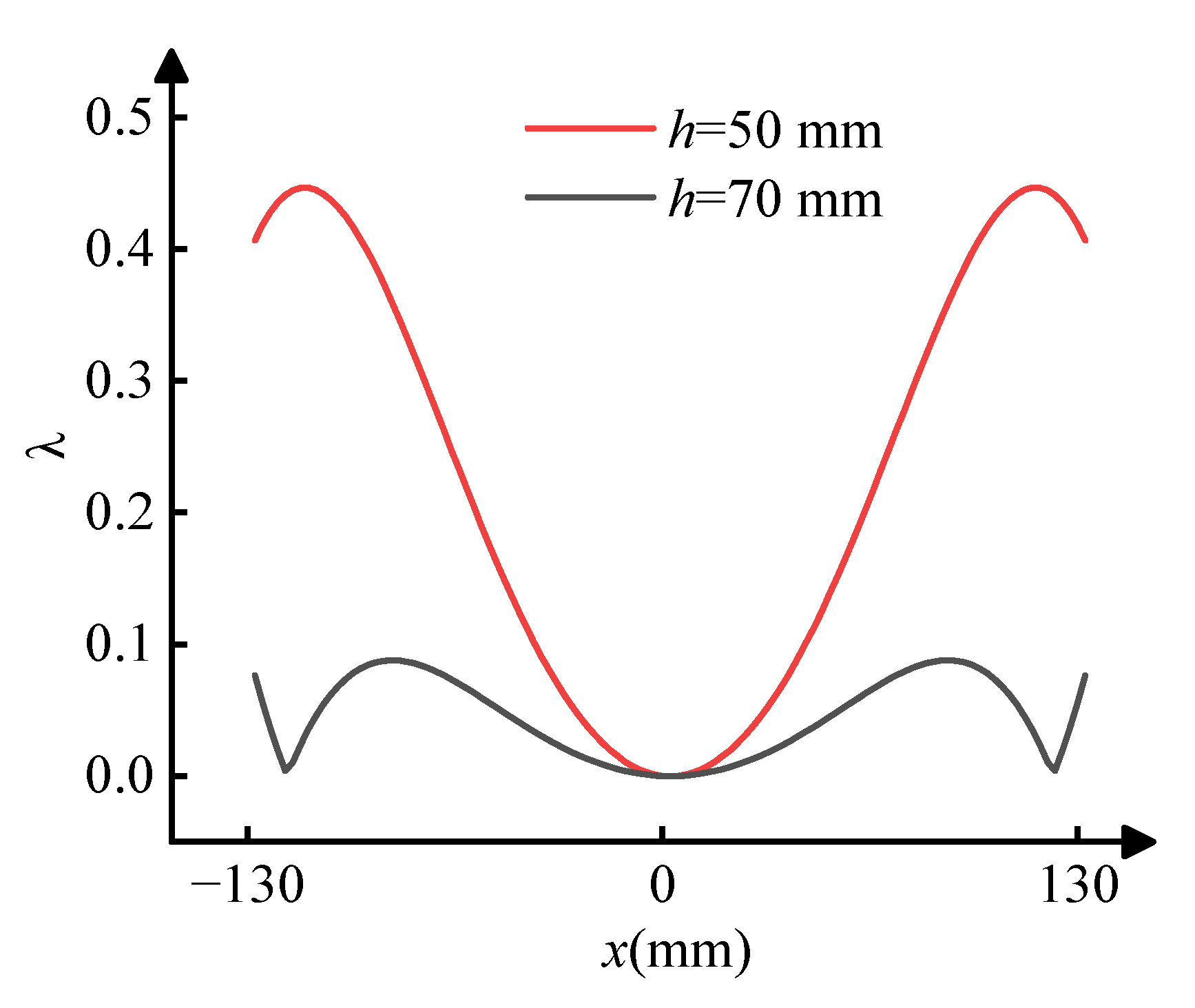
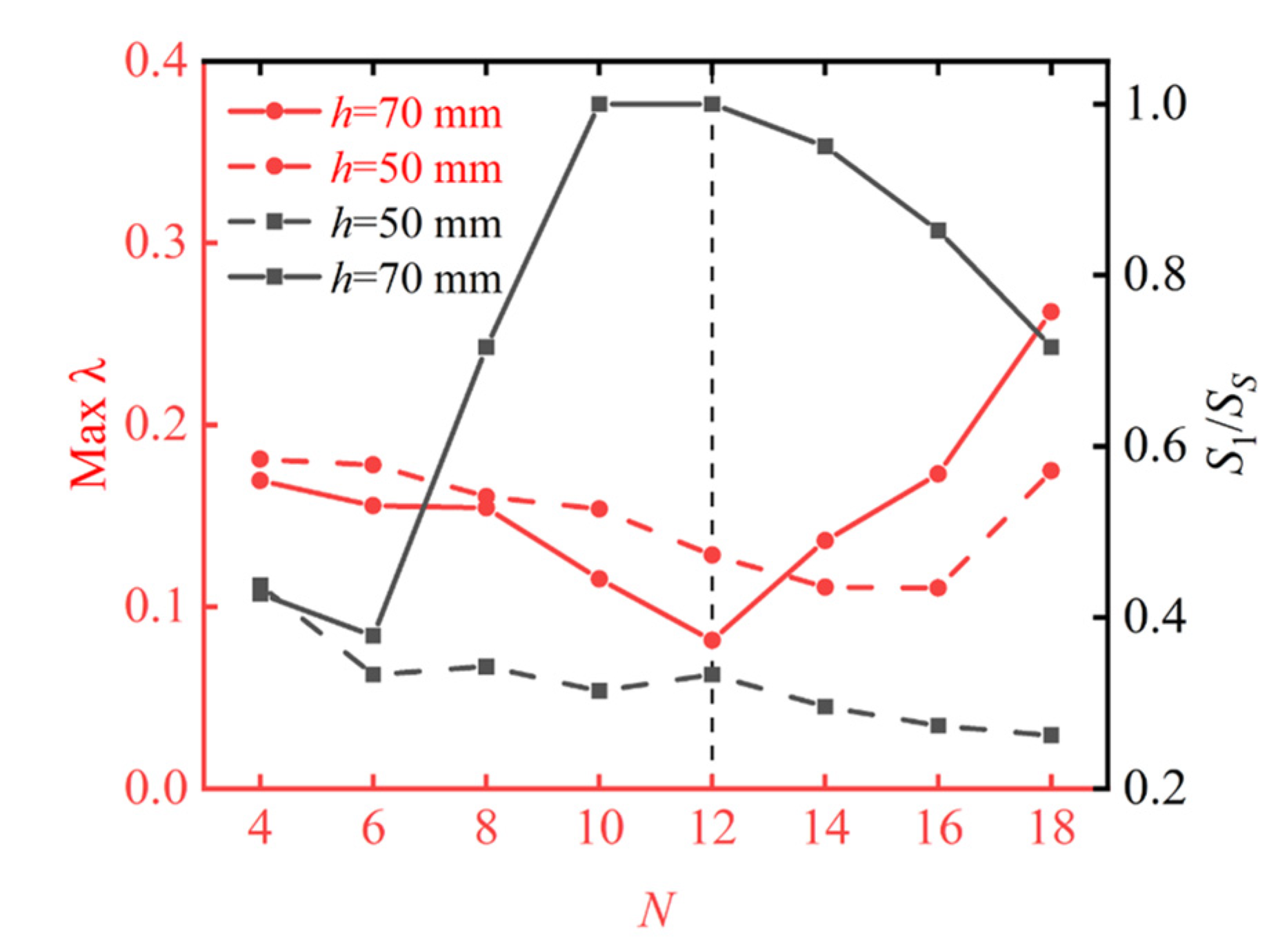
2.2. Analysis of the Circular Coil Turns

When the outer diameter of the Tx coil is determined, the average radius of the coil decreases as the turn numbers of the coil increase. In addition, the distribution of BZ calculated by Equation (1) ignores the single-turn coil thickness, and the results may differ from the actual value. By using COMSOL simulation software, the influence of different circular coil turn numbers on the BZ distribution in the S-plane can be more accurately analyzed. The maximum discretization of BZ and the ratio of UMF area to the total area of the S-plane with h = 50 mm and h = 70 mm under different coil turn numbers are shown in Figure 4.
As can be seen from Figure 4, the distribution of BZ and the area of the UMF region at h = 70 mm is related to the turn numbers N of the circular coil. When N = 12, the distribution of BZ in the entire S-plane meets the conditions of a UMF; at the same time, the fluctuation of BZ is minimal. However, for h = 50 mm, as shown in Figure 4, by adjusting the turn numbers of the circular coil, the area of the UMF region S1 always stays at a low level. Some other methods need to be taken to increase the area of the UMF region when h = 50 mm.

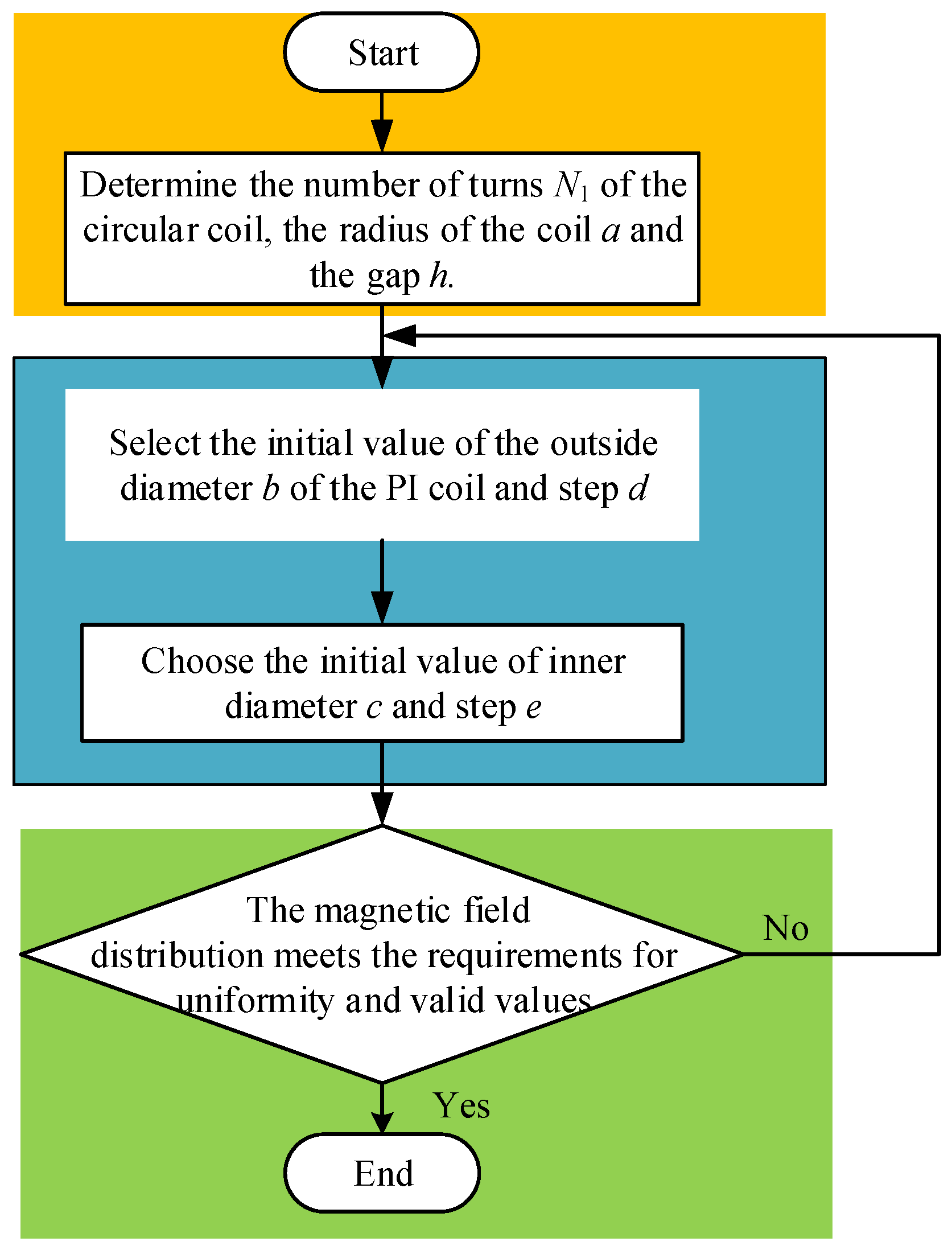
2.3. Constructing UMF with a PI Coil

In the WPT system shielding measures, there is a method of reactive resonant shielding, which suppress the leakage magnetic field by passive coil [22]. Similarly, we can utilize the method of adding a PI coil to enhance or weaken the magnetic field in a specific area, and thus achieve the purpose of building a UMF.
The proposed magnetic coupler with an integrated PI coil is shown in Figure 5. When the alternating magnetic field generated by the Tx coil passes through the PI coil, an induced electromotive force is generated on the coil, and the induction coil will produce a magnetic field with opposite direction. Using this property, combined with an induced magnetic field distribution of circular coil, the parameters of the PI coil are designed to construct a UMF.
The induced voltage Vind generated on the PI coil can be expressed as
V i n d = d ϕ d t = j ω B z e j ω t S 2
where φ is the magnetic flux through the plane PI coil located, and S2 is the area of the PI coil. The induced current Iind in the PI coil can be expressed as
I i n d = V i n d Z 2 = V i n d j ω L 2 + R 2
where L2 is the self-inductance of the PI coil and R2 is the parasitic resistance of the PI coil. According to Equation (1), the magnetic induction intensity generated by the PI coil at any point P on the S-plane can be calculated as
B z = N μ 0 I i n d 4 π L d l × e r r 2
Since the magnetic induction intensity satisfies the law of superposition, the magnetic induction intensity at any point P on the S-plane is the sum of the magnetic induction intensity generated by Tx coil and the magnetic induction intensity generated by the PI coil, expressed as
B z = B z + B z
According to (3)–(6), when the parameters of the Tx coil are fixed, the area S2 of the PI coil determines the magnetic induction intensity at point P. The direction of the current in the PI coil can be determined by Lenz’s law, as shown in Figure 6.
Since AUV needs to maintain a radial offset of at least 30 mm; in other words, the inner diameter of the PI coil should be greater than 130 mm, assuming c = 130 mm. Figure 7 shows the magnetic induction intensity distribution on line l1 varying with the size of the PI coil.
The effect of PI coil on the BZ distribution can be concluded as per the following:
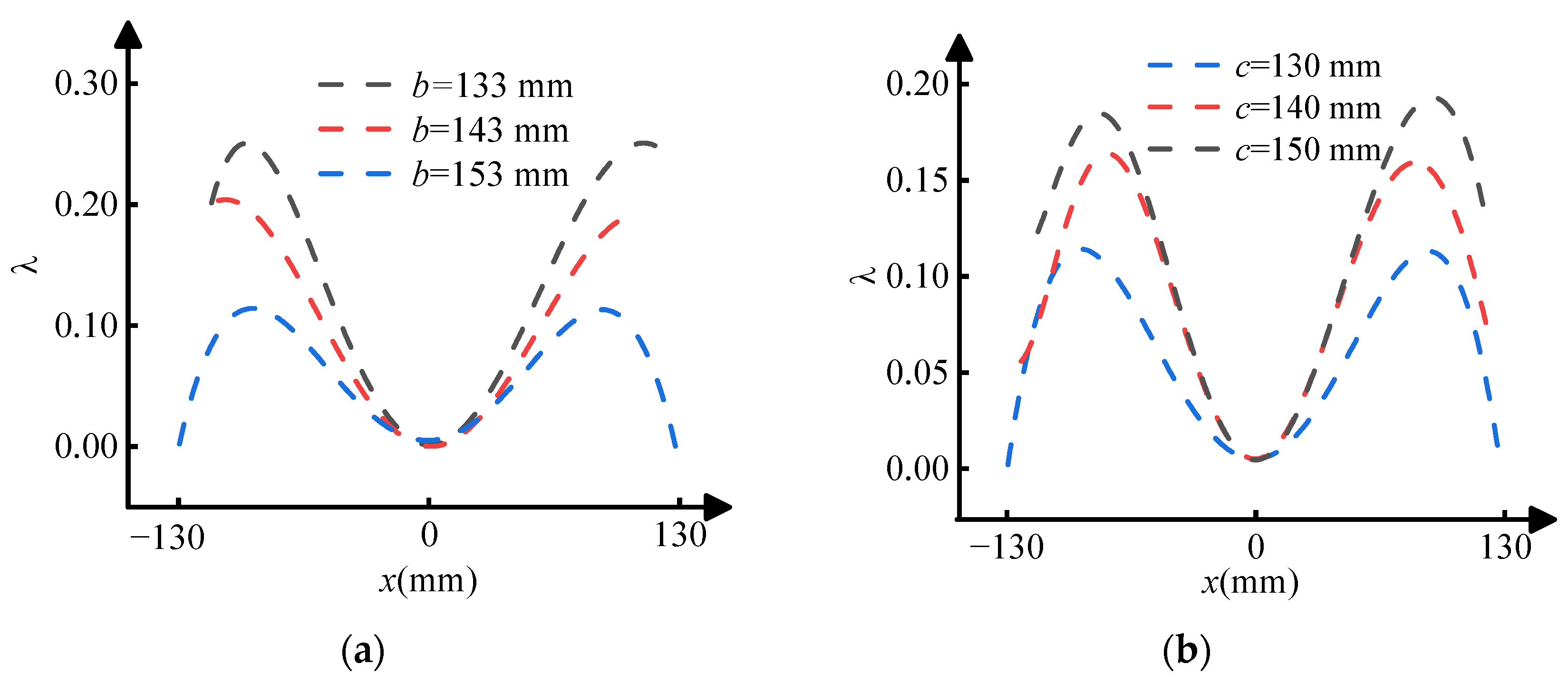
  • By adjusting the parameters of the PI coil, the fluctuation of magnetic induction intensity can be reduced to extend the UMF area.
  • The deviation of BZ distribution on line l1 reduces with the increase in the outer diameter of PI coil b. The outer diameter of the PI coil can be fixed to the inner diameter of the Tx coil.
  • When the outer diameter of PI coil b is determined, the deviation of BZ distribution on line l1 reduces as the inner diameter of PI coil c decreases.
The above discussion shows that the introduction of a PI coil can improve the uniformity of the induced magnetic field distribution. The values of parameters b and c that meet the requirements can be obtained through the flowchart shown in Figure 8.
It is finally determined that b = 153 mm, which is the outermost turn of the PI coil when wound tightly to the inside of the Tx coil, and the inner diameter c is selected as 130 mm. Figure 9 shows the magnetic induction intensity distribution on the S-plane when adding a PI coil and using only circular coil.
Comparing Figure 9a,b, it can be clearly seen that the magnetic induction intensity at the center of the corresponding area of the plane has increased, and the distribution of the magnetic induction intensity is more uniform after adding a PI coil.
From the above analysis, it can be seen that when the gap h between the Tx coil and the Rx coil is 50 mm, the PI coil can improve the anti-offset ability of the system; the parameters of the magnetic coupling mechanism are listed in Table 2. When h is 70 mm, the system maintains good anti-offset ability, and there is no need to start a PI coil.

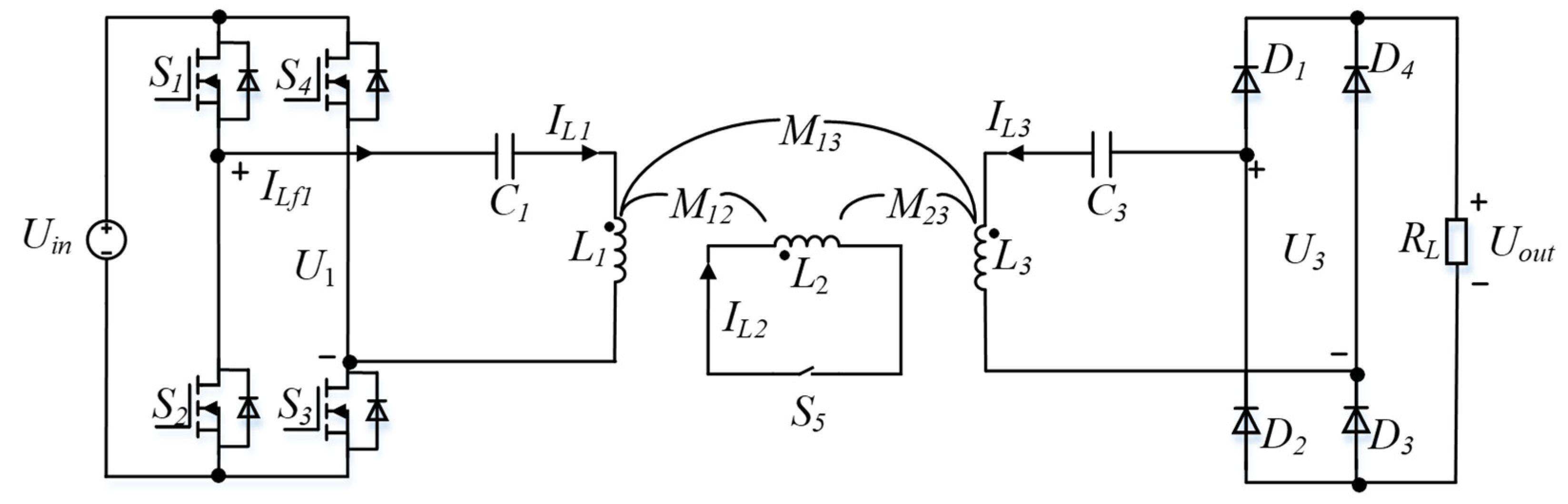
3. Circuit Design and Analysis

3.1. System Circuit Structure Design with a PI Coil

The proposed WPT system circuit structure with a PI coil is shown in Figure 10. The DC voltage Uin is converted to AC voltage U1 through a full-bridge inverter consisting of four MOSFETS (S1S4). The power is transmitted from the primary side to the secondary side through the resonant network and electromagnetic coupling mechanism. C1 and C3 are the compensation capacitors. The electromagnetic coupling mechanism consists of Tx coil L1, Rx coil L3, and PI coil L2. M12, M13, and M23 represent the coupling between each coil, respectively. Switch S5 controls the switching of the PI coil. The DC voltage on load RL is obtained by the secondary side compensation network output voltage U3 through a rectifier consisting of four DIODES (D1D4). Moreover, the S-S compensation topology has the characteristics of simple structure and high efficiency, which is suitable for underwater WPT applications with limited space.

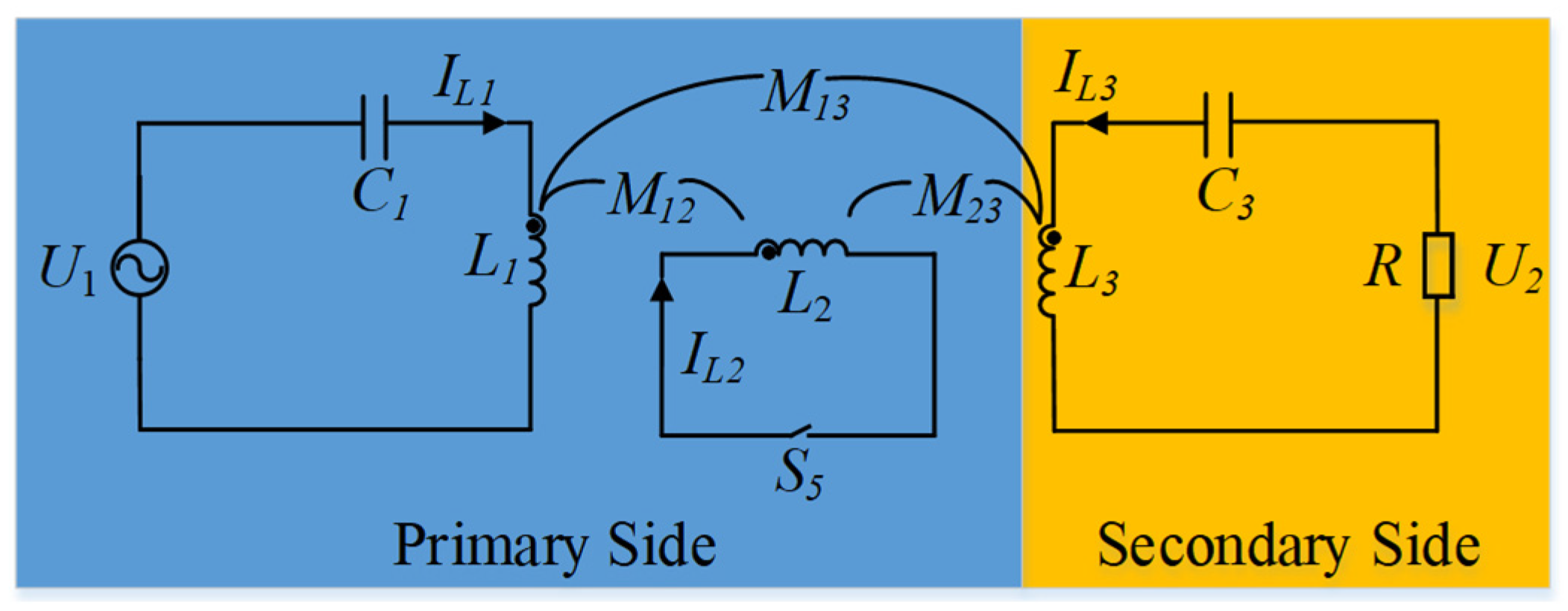
3.2. Circuit Modelling Analysis

To simplify the analysis, the fundamental harmonic approximation is used and all higher-order harmonics are ignored. The simplified model of the proposed WPT system is shown in Figure 11.
The root mean square (RMS) value of the fundamental voltage component can be expressed as
U 1 = 2 2 U i n π
The equivalent load resistance RL can be calculated as [23]
R = 8 π 2 R L
When switch S5 is turned on, according to Kirchhoff’s voltage law, the following equation can be obtained.
U 1 0 0 = j ω L 1 + 1 j ω C 1 j ω M 12 j ω M 13 j ω M 12 j ω L 2 j ω M 23 j ω M 13 j ω M 23 j ω L 3 + 1 j ω C 3 + R · I 1 I 2 I 3
where ω represents the angular frequency of the WPT system. When the system is resonant, the relationship between the circuit components is expressed as
ω L 1 = 1 ω C 1 ω L 3 = 1 ω C 3
By substituting (10) into (9), the current can be obtained as
I 1 = ω M 23 2 + L 2 R j ω M 12 2 R + A j U 1 I 2 = M 12 R ω M 13 M 23 j ω M 12 2 R j A U 1 I 3 = L 2 M 13 M 12 M 23 M 12 2 R + A j U 1
where A = ω ( L 2 M 13 2 2 M 12 M 13 M 23 ) . When switch S5 is turned off, the PI coil no longer functions, and the circuit structure becomes a typical S-S compensation.

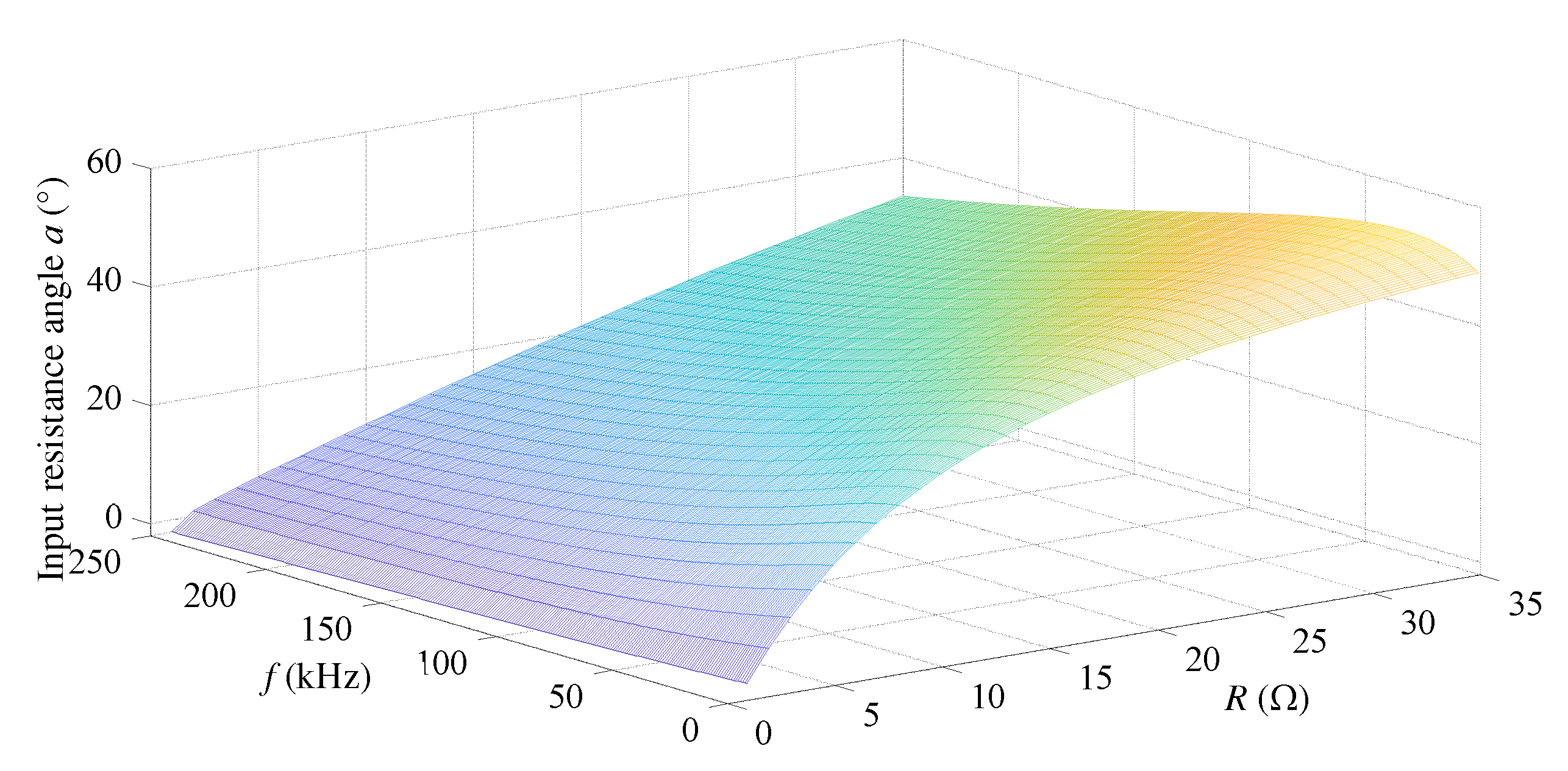
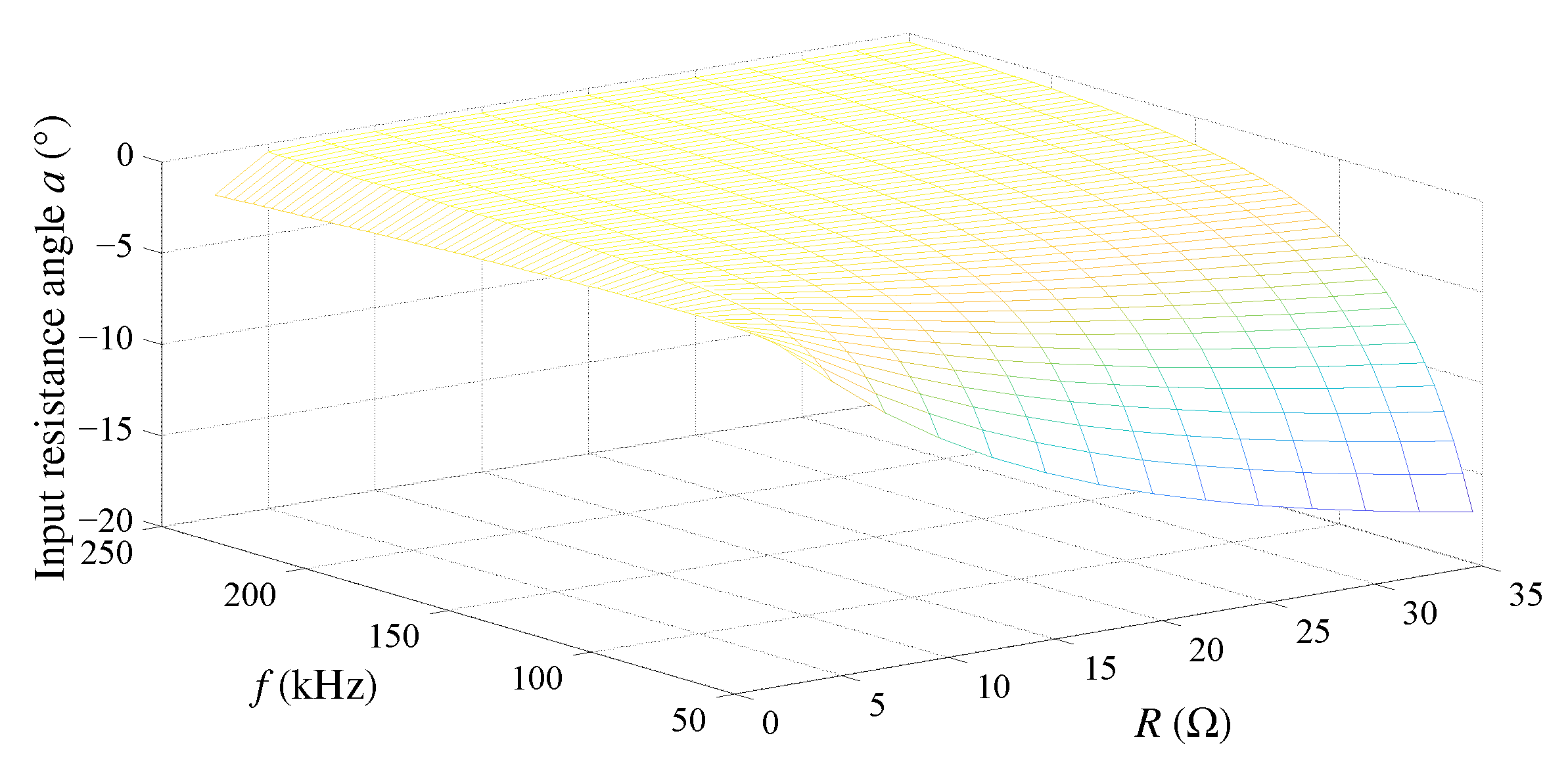
3.3. Analysis of the ZPA Characteristics of the Proposed WPT System

Maintaining ZPA operating characteristics to avoid reactive power loss is critical to improving the overall efficiency of the WPT system [24]. The S-S compensation structure has ZPA operation characteristics [25], but when a PI coil is added, the input impedance of the WPT system becomes
Z i n = U 1 I L f 1 = R i n + j X i n = ω 2 M 12 2 M 23 2 R A L 2 R ω 2 M 23 4 + L 2 2 R 2 + j A ω M 23 2 ω M 12 2 R 2 L 2 ω 2 M 23 4 + L 2 2 R 2 α ( rad ) = arctan X i n Z i n
where α represents the input impedance angle. The addition of a PI coil brings an imaginary part to the input impedance, and ZPA can no longer be realized. As can be seen from (12), the input impedance angle α is related to the angular frequency ω, equivalent load R, the inductance of PI coil L2, and coupling between coils. M12, M23, and M13 are 1.9 µH, 0.1 µH, and 7.51 µH, respectively. With the calculation of MATLAB, the relationship among the input impedance angle α, load R and system frequency f is shown in Figure 12.
As can be seen from Figure 12, the input impedance angle α tends to decrease as the load increases, but the decrease in α can be mitigated by increasing the system frequency f. Considering that when the system frequency is higher than 300 kHz, the propagation of high-frequency electromagnetic fields in seawater will produce large eddy current losses [26], the system operating frequency is selected as 244 kHz.
Equation (12) is simplified to obtain the real and imaginary parts of the input impedance.
r e a l ( Z i n ) = ω 2 M 12 2 M 23 2 R A L 2 R ω 2 M 23 4 + L 2 2 R 2 i m a g ( Z i n ) = A ω M 23 2 ω M 12 2 R 2 L 2 ω 2 M 23 4 + L 2 2 R 2
Since the value of M23 is very small, it can be omitted in the analysis. The imaginary part of the input impedance can be expressed as
i m a g ( Z i n ) = ω M 12 2 L 2
It means that the introduction of a PI coil brings an imaginary part to the input impedance, which is related to M12. By adjusting the value of compensation capacitor C1, the ZPA characteristics can be maintained in the WPT system and the relationship between C1 and mutual inductance M12 is expressed as
j ω L 1 + 1 j ω C 1 = j ω M 12 2 L 2
Figure 13 shows the relationship between the input impedance angle and system frequency f, load R after adjusting C1. It can be seen that when the operating frequency is set to 244 kHz, the ZPA characteristics of the system will not be affected as the load changes.

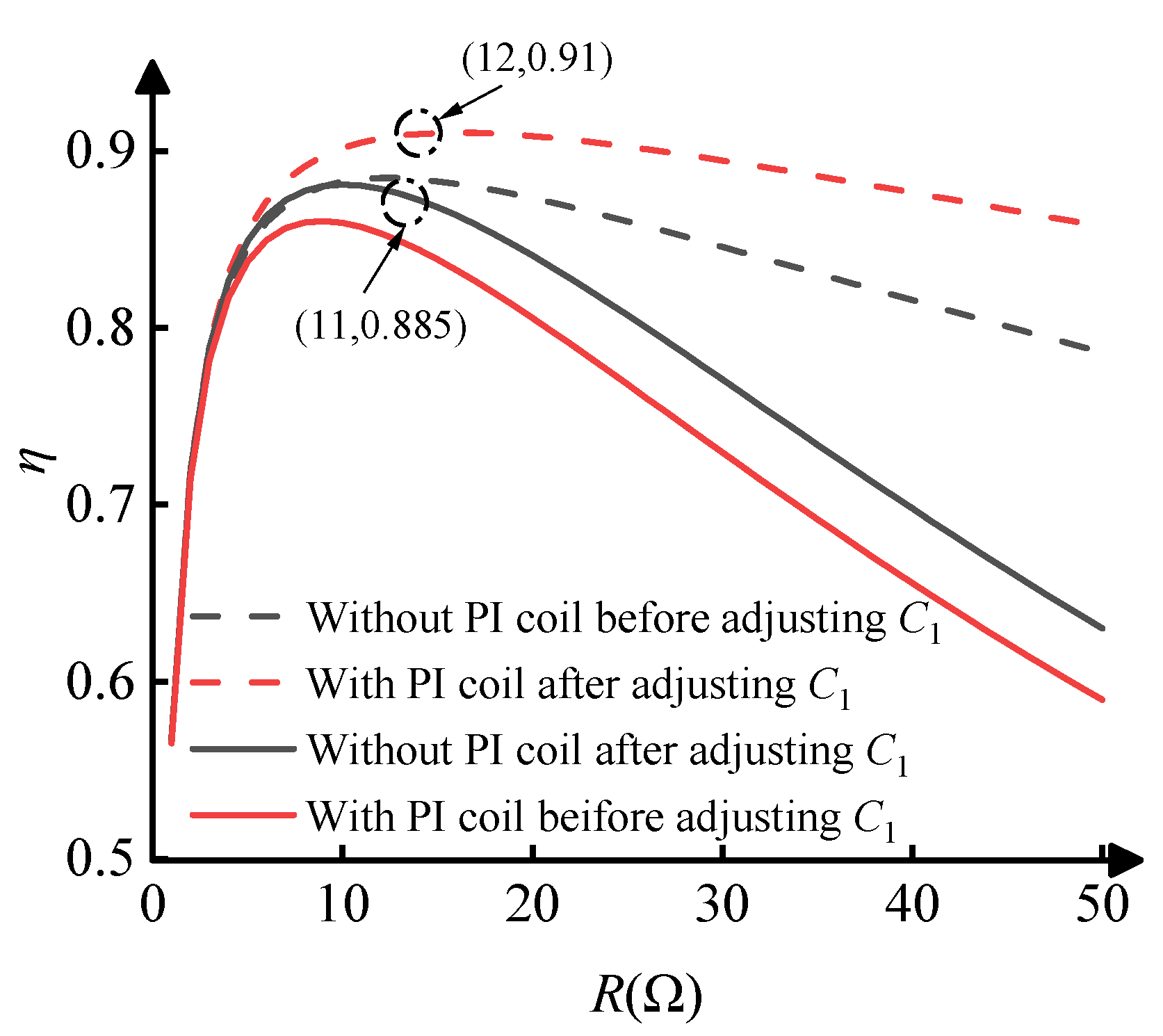
3.4. System Efficiency Analysis

This section focuses on the effect of a PI coil on the power transmission characteristics of the WPT system. In the above analysis, the influence of the parasitic resistance of each coil on the system is not taken into account because its value is very small. However, when analyzing system efficiency, it cannot be ignored. In addition, in the marine environment, the impact of eddy current losses caused by the propagation of electromagnetic fields in seawater on WPT system efficiency also needs to be considered. When a PI coil is operating, the power transfer efficiency η and system output power Pout can be expressed as
η = I 3 2 R P e d d y + I 1 2 R 1 + I 2 2 R 2 + I 3 2 ( R 3 + R ) P o u t = I 3 2 R
where R1, R2, and R3 are the parasitic resistance of L1, L2, and L3, respectively. The effect of load changes on power transfer efficiency is shown in Figure 14. It can be seen that when the load changes within 0~50 Ω, the power transfer efficiency of the WPT system after adding a PI coil and without a PI coil are consistent, both increase sharply at first, and then decrease slowly. Meanwhile, the introduction of a PI coil reduces the optimal efficiency of the system by about 3%.

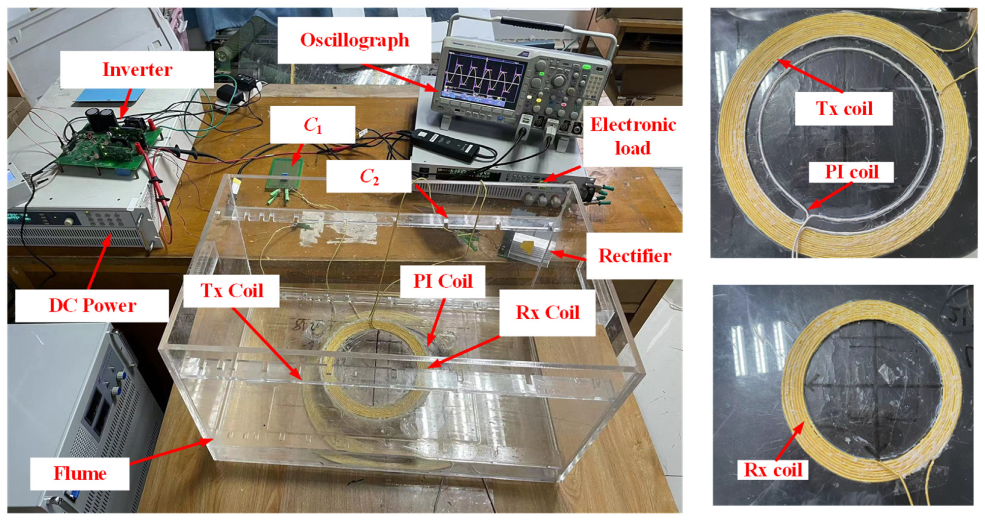
4. Experimental Verification

An experimental platform is built to verify the proposed structure, as shown in Figure 15. To reduce the skin and proximity effects, the Litz wires are employed for the construction of Tx, Rx, and PI coils. They are wound by AWG 38 litz wires with 400 strands. The structure of the Tx coil, Rx coil, and a PI coil are also shown in Figure 15. The water tank is built to realistically simulate the marine environment, and the gap between coils is filled by saltwater with a salinity of 4‰. The electronic load is used to simulate the load change in the WPT system. The parameters of the proposed WPT system are listed in Table 3.

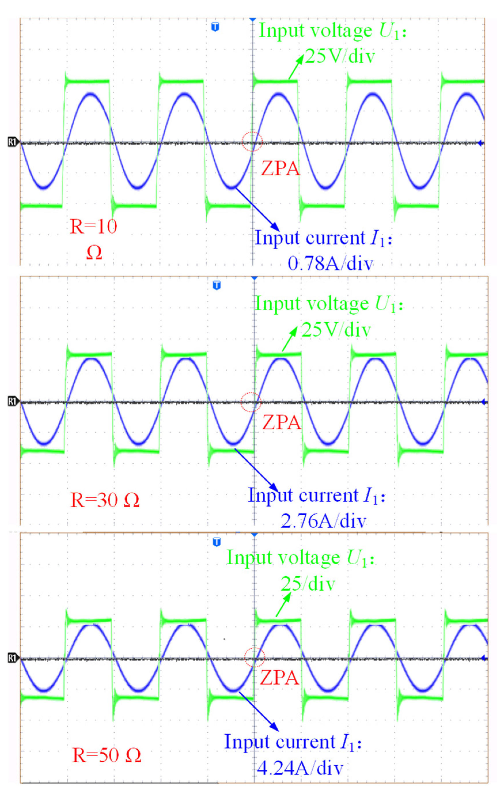
4.1. Verification of ZPA Characteristics of the Proposed WPT System

The ZPA characteristics of the system are verified by measuring the phase angle of the input voltage and current with an Oscilloscope. Considering that the internal resistance of the batteries does not change much during the charging process, the resistance of the electronic load gradually increases from 10 to 50 Ω. The experimental waveforms of input voltage and current are shown in Figure 16.
As can be seen in Figure 16, the phase angle of input voltage and current does not change with the variation in load resistance. Through the above analysis and experiment, it can be verified that the WPT system with the addition of a PI coil is still able to maintain the ZPA characteristics after adjusting the compensation capacitor C1.

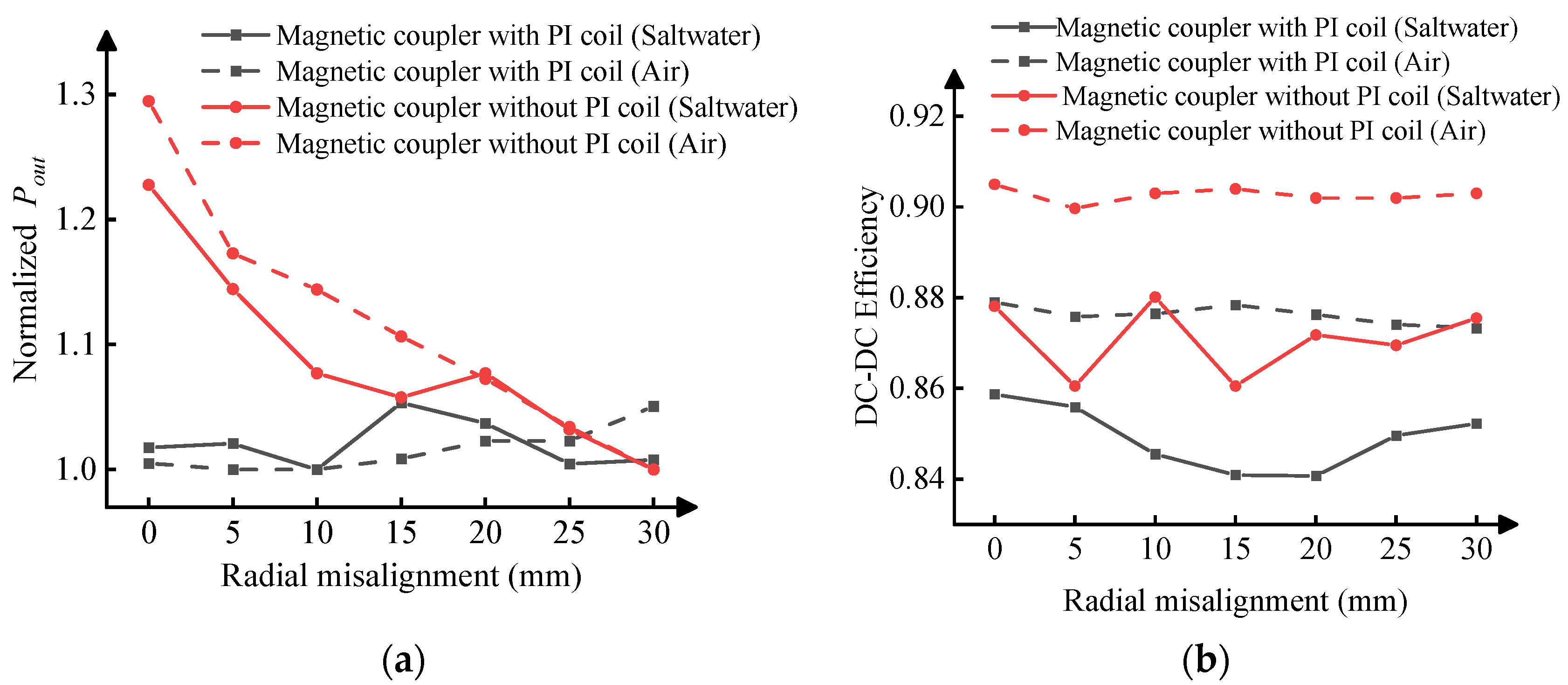
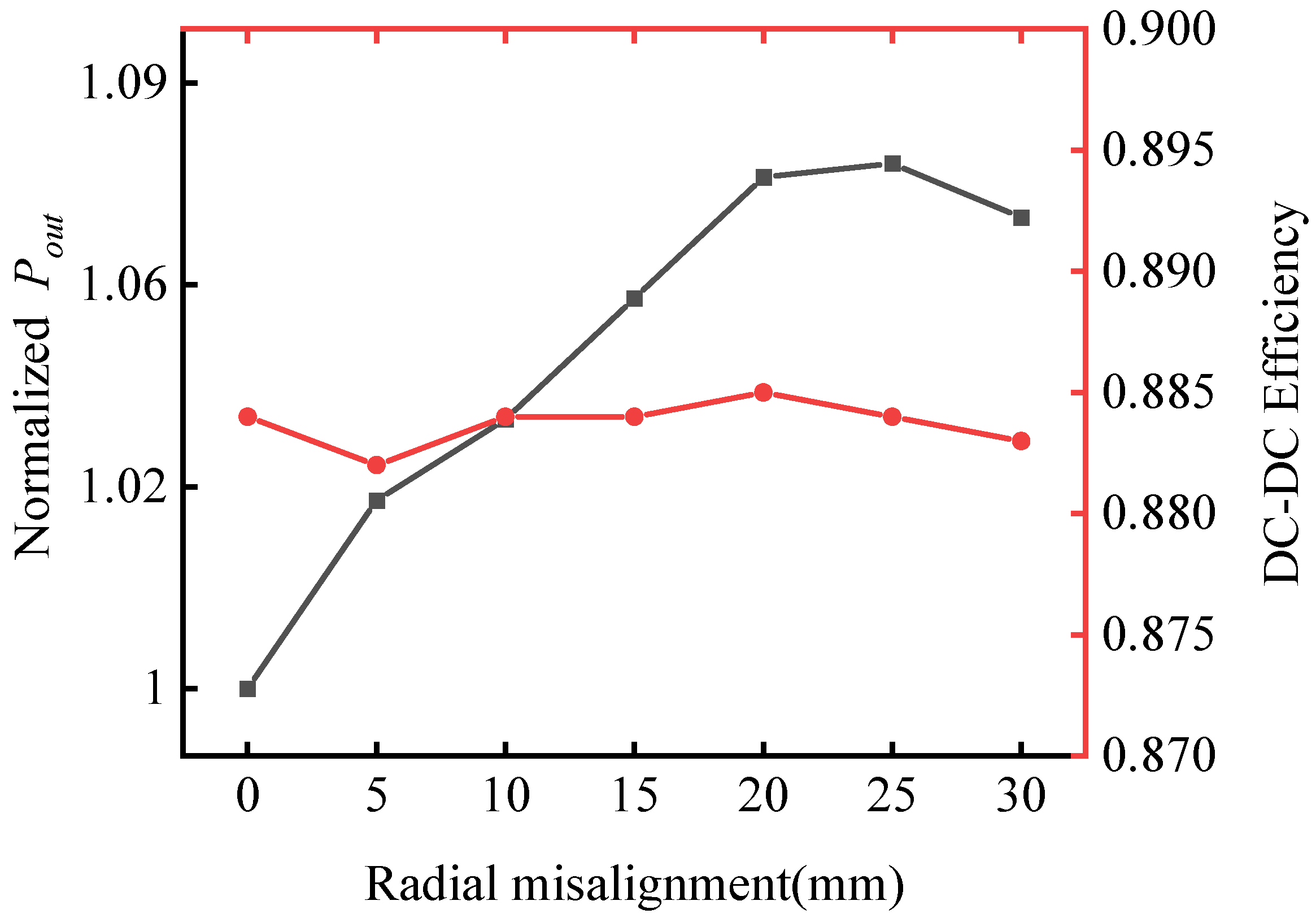
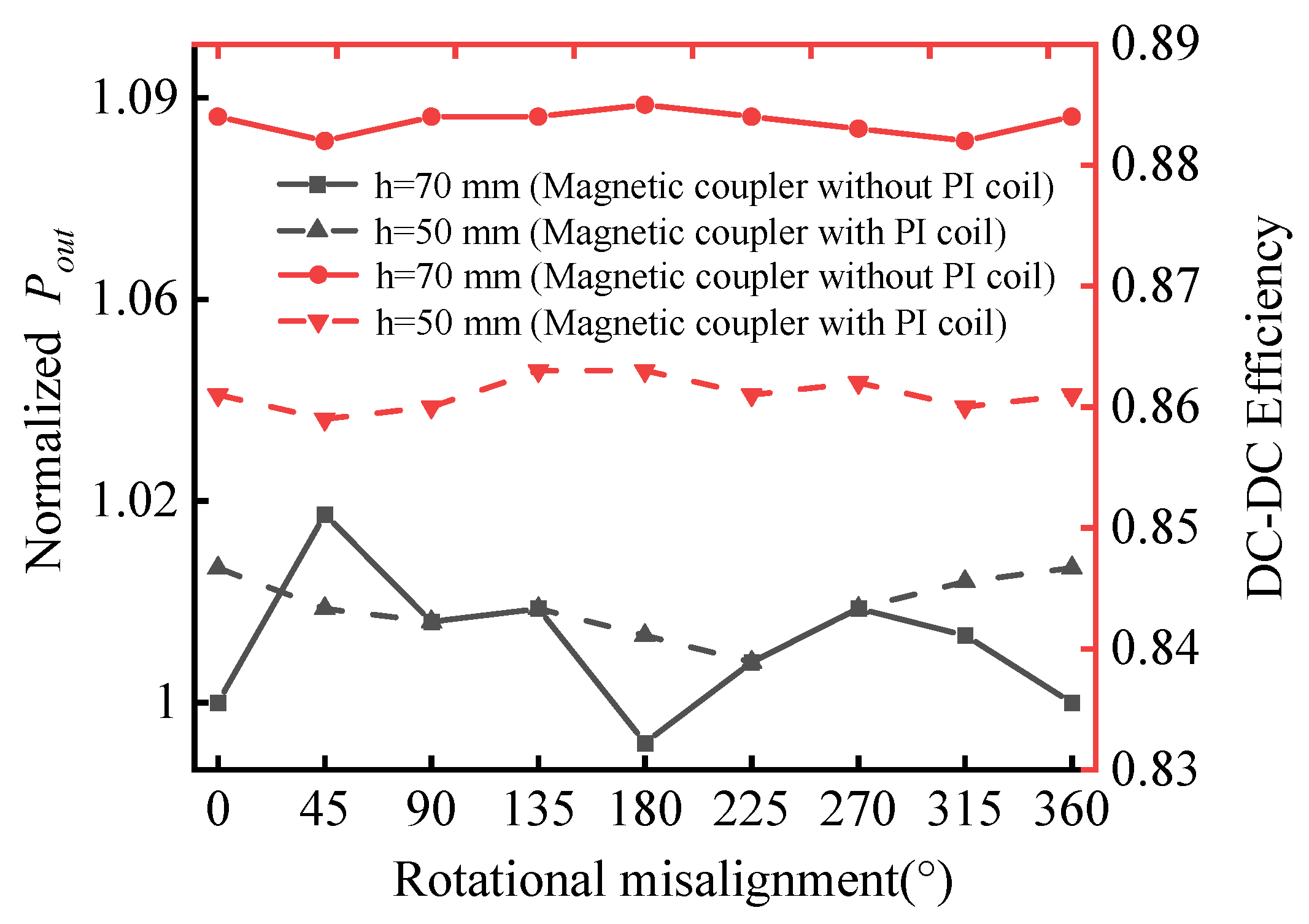
4.2. Verification of System Output Characteristics

The introduction of the PI coil changes the output characteristic of the WPT system, and in order to compare the fluctuation of output power, the output power of the system is normalized, as shown in Figure 17. In addition, the comparison test of the proposed WPT system in air and saltwater is added to verify the function of the PI coil.
Compared with the output power of the WPT system without a PI coil, the fluctuation of output power decreases by 17% with the introduction of a PI coil, as can be seen in Figure 17. The stability of the output power of the system is improved significantly with the addition of a PI coil. A PI coil brings negative effects to the transmission efficiency, which cause approximately a 3% decrease in power transfer efficiency compared with the WPT system without a PI coil. Figure 18 shows the output power and efficiency of the WPT system varying with radial misalignments when only a circular coil is used at the Tx coil when h = 70 mm.
As can be seen from Figure 18, when h = 70 mm, the WPT system using only a circular coil at the Tx coil can meet the fluctuation of output power within 0.08, while maintaining the power transfer efficiency at 88.5%. Figure 19 shows the output power and efficiency of the WPT system varying with rotational misalignments.
As can be seen from Figure 19, the output power and efficiency of the WPT system vary very little as the rotational degree changes. The introduction of a PI coil does not affect the good resistance to rotational misalignments of the circular coil.

5. Discussion

A method to improve the anti-offset ability of the WPT system by using PI coil is proposed in this paper, and the influence of PI coil on the magnetic field distribution of circular coil is studied from the perspective of deviation analysis. However, the principle and function of PI coil have not been deeply analyzed. In future work, the UMF construction method with PI coil will be studied by accurate theoretical analysis and experimental verification. Furthermore, mutual inductance will be taken into consideration in the parameter optimization of PI coil to deal with intricate position misalignments in the WPT system.
Although the stability of the output power of the system under different misalignments has been improved with the introduction of a PI coil, it has a certain negative impact on the power transfer efficiency. In the subsequent work, a design tradeoff among power transfer efficiency, output power stability, and coils’ geometric layout will be investigated.

6. Conclusions

A WPT system with circular coils and a PI coil for an autonomous underwater vehicle is proposed in this paper. A PI coil is introduced to enhance or weaken the magnetic field in a specific area and build a UMF in a WPT system. The theoretical analysis shows that the proposed magnetic coupler can effectively eliminate the deviation of magnetic field distribution in comparison with traditional circular spiral coils. Experimental results show that the addition of a PI coil significantly improves the stability of the system’s output power and power transfer efficiency. The WPT system’s output power changes within 5.5% and the power transfer efficiency maintains at approximately 84.5% in arbitrary radial positions with an axial distance of 50 mm in saltwater. Meanwhile, compared to the WPT system without a PI coil, the fluctuation of output power is reduced by 17%.

Author Contributions

Conceptualization, H.W. and J.L.; methodology, H.W., J.L. and K.Z.; software, J.L. and Z.Y.; validation, H.W., J.L. and Z.Y.; formal analysis, K.Z., J.Y. and J.L.; investigation, H.W. and K.Z.; resources, B.S. and X.T.; data curation, J.L., J.Y. and Z.Y.; writing—original draft preparation, H.W. and J.L.; writing—review and editing, H.W., J.L. and K.Z.; visualization, J.L.; supervision, B.S. and X.T.; project administration, K.Z. and H.W.; funding acquisition, K.Z. and H.W. All authors have read and agreed to the published version of the manuscript.

Funding

This work was supported in part by the National Natural Science Foundation of China under Grant 52171338, in part by the China Postdoctoral Science Foundation under Grant 2021M702638, in part by the Natural Science Basic Research Plan in Shaanxi Province of China under Grant 2023-JC-QN-0475, and in part by the Starting Research Fund for Postdoctoral Researcher from Xi’an University of Technology under Grant 119-451121005.

Institutional Review Board Statement

Not applicable.

Informed Consent Statement

Not applicable.

Data Availability Statement

Not applicable.

Conflicts of Interest

The authors declare no conflict of interest.

References

  1. Feng, H.; Tavakoli, R.; Onar, O.C.; Pantic, Z. Advances in High-Power Wireless Charging Systems: Overview and Design Considerations. IEEE Trans. Transp. Electrif. 2020, 6, 886–919. [Google Scholar] [CrossRef]
  2. Harakare, A.; Barhate, N.; Randad, N.; Varghese, A.G.; Gupta, A.; Dave, P.; Modi, S.; Shrivastava, A.; Khare, L.; Raj, S. Design of Battery Management System for an Autonomous Underwater Vehicle. In Proceedings of the OCEANS 2022—Chennai, Chennai, India, 21–24 February 2022. [Google Scholar]
  3. Painter, H.; Flynn, J. Current and Future Wet-Mate Connector Technology Developments for Scientific Seabed Observatory Applications; Oceans: Boston, MA, USA, 2006; pp. 1–6. [Google Scholar]
  4. Mohsan, S.A.H.; Khan, M.A.; Mazinani, A.; Alsharif, M.H.; Cho, H.-S. Enabling Underwater Wireless Power Transfer towards Sixth Generation (6G) Wireless Networks: Opportunities, Recent Advances, and Technical Challenges. J. Mar. Sci. Eng. 2022, 10, 1282. [Google Scholar] [CrossRef]
  5. Yan, Z.; Zhang, Y.; Song, B.; Zhang, K.; Kan, T.; Mi, C. An LCC-P Compensated Wireless Power Transfer System with a Constant Current Output and Reduced Receiver Size. Energies 2019, 12, 172. [Google Scholar] [CrossRef] [Green Version]
  6. Kan, T.; Mai, R.; Mercier, P.P.; Mi, C.C. Design and Analysis of a Three-Phase Wireless Charging System for Lightweight Autonomous Underwater Vehicles. IEEE Trans. Power Electron. 2018, 33, 6622–6632. [Google Scholar] [CrossRef]
  7. Wu, S.; Cai, C.; Chai, W.; Li, J.; Cui, Q.; Yang, S. Uniform Power IPT System With Quadruple-Coil Transmitter and Crossed Dipole Receiver for Autonomous Underwater Vehicles. IEEE Trans. Ind. Appl. 2022, 58, 1289–1297. [Google Scholar] [CrossRef]
  8. Zeng, Y.; Rong, C.; Lu, C.; Tao, X.; Liu, X.; Liu, R.; Liu, M. Misalignment Insensitive Wireless Power Transfer System Using a Hybrid Transmitter for Autonomous Underwater Vehicles. IEEE Trans. Ind. Appl. 2022, 58, 1298–1306. [Google Scholar] [CrossRef]
  9. Yan, Z.; Zhang, Y.; Kan, T.; Lu, F.; Zhang, K.; Song, B.; Mi, C.C. Frequency Optimization of a Loosely Coupled Underwater Wireless Power Transfer System Considering Eddy Current Loss. IEEE Trans. Ind. Electron. 2019, 66, 3468–3476. [Google Scholar] [CrossRef]
  10. Liu, P.; Gao, T.; Zhao, R.; Mao, Z. A Novel Conformal Coil Structure Design of Wireless Power Transfer System for Autonomous Underwater Vehicles. J. Mar. Sci. Eng. 2022, 10, 875. [Google Scholar] [CrossRef]
  11. Wang, Y.; Song, B.; Mao, Z. Application of Shielding Coils in Underwater Wireless Power Transfer Systems. J. Mar. Sci. Eng. 2019, 7, 267. [Google Scholar] [CrossRef] [Green Version]
  12. Yan, Z.; Wu, M.; Zhao, C.; Hu, Q.; Zhu, L.; Qiao, L.; Wang, L. Free-Rotation Wireless Power Transfer System Based on Composite Anti-Misalignment Method for AUVs. IEEE Trans. Power Electron. 2023, 38, 4262–4266. [Google Scholar] [CrossRef]
  13. Yan, Z.; Zhao, C.; Hu, Q.; Wu, M.; Qiao, L.; Zhang, K.; Hu, Y. An Underwater Inductive Power Transfer System with a Compact Receiver and Reduced Eddy Current Loss. J. Mar. Sci. Eng. 2022, 10, 1900. [Google Scholar] [CrossRef]
  14. Wang, T.; Zhao, Q.; Yang, C. Visual navigation and docking for a planar type AUV docking and charging system. Ocean. Eng. 2021, 224, 108744. [Google Scholar] [CrossRef]
  15. Wang, S.; Hu, Z.; Rong, C.; Lu, C.; Chen, J.; Liu, M. Planar Multiple-Antiparallel Square Transmitter for Position-Insensitive Wireless Power Transfer. IEEE Antennas Wirel. Propag. Lett. 2018, 17, 188–192. [Google Scholar] [CrossRef]
  16. Zhang, Y.; Wang, L.; Guo, Y.; Zhang, Y. Optimisation of planar rectangular coil achieving uniform magnetic field distribution for EV wireless charging based on genetic algorithm. IET Power Electron. 2019, 12, 2706–2712. [Google Scholar] [CrossRef]
  17. Zhang, C.; Wang, W.; Xu, C.; Yang, J. Research on Uniform Magnetic Field Compensation Structure of Array Circular Coils for Wireless Power Transfer. IEEE Trans. Magn. 2021, 57, 1–5. [Google Scholar] [CrossRef]
  18. Xun, L.; Hui, S.Y. Optimal Design of a Hybrid Winding Structure for Planar Contactless Battery Charging Platform. IEEE Trans. Power Electron. 2008, 23, 455–463. [Google Scholar] [CrossRef]
  19. Bharadwaj, A.; Srivastava, V.K.; Sharma, A.; Reddy, C.C. A Switchable Multicoil Antenna With Booster Coil to Improve Coverage in WPT Systems. IEEE Trans. Antennas Propag. 2022, 70, 2490–2498. [Google Scholar] [CrossRef]
  20. Mirbozorgi, S.A.; Maghsoudloo, E.; Bahrami, H.; Sawan, M.; Gosselin, B. Multi-resonator arrays for smart wireless power distribution: Comparison with experimental assessment. IET Power Electron. 2020, 13, 4183–4193. [Google Scholar] [CrossRef]
  21. Pahlavan, S.; Shooshtari, M.; Jafarabadi Ashtiani, S. Star-Shaped Coils in the Transmitter Array for Receiver Rotation Tolerance in Free-Moving Wireless Power Transfer Applications. Energies 2022, 15, 8643. [Google Scholar] [CrossRef]
  22. Kim, J.; Kim, J.; Kong, S.; Kim, H.; Suh, I.S.; Suh, N.P.; Cho, D.H.; Kim, J.; Ahn, S. Coil Design and Shielding Methods for a Magnetic Resonant Wireless Power Transfer System. Proc. IEEE 2013, 101, 1332–1342. [Google Scholar] [CrossRef]
  23. Zhang, W.; Wong, S.; Tse, C.; Chen, Q. Analysis and Comparison of Secondary Series- and Parallel-Compensated Inductive Power Transfer Systems Operating for Optimal Efficiency and Load-Independent Voltage-Transfer Ratio. IEEE Trans. Power Electron. 2014, 29, 2979–2990. [Google Scholar] [CrossRef]
  24. Yang, L.; Ren, L.; Shi, Y.; Wang, M.; Geng, Z. Analysis and Design of a S/S/P-Compensated Three-coil Structure WPT System With Constant Current and Constant Voltage Output. IEEE J. Emerg. Sel. Top. Power Electron. 2022. early access. [Google Scholar] [CrossRef]
  25. Chen, Y.; Zhang, H.; Park, S.-J.; Kim, D.-H. A Switching Hybrid LCC-S Compensation Topology for Constant Current/Voltage EV Wireless Charging. IEEE Access 2019, 7, 133924–133935. [Google Scholar] [CrossRef]
  26. Bana, V.; Kerber, M.; Anderson, G.; Rockway, J.D.; Phipps, A. In Underwater wireless power transfer for maritime applications. In Proceedings of the 2015 IEEE Wireless Power Transfer Conference (WPTC), Boulder, CO, USA, 13–15 May 2015. [Google Scholar]
Figure 1. Schematic diagram of charging plane S formed by the circular coil.
Jmse 11 00566 g001
Figure 2. BZ distribution in the S-plane with different h. (a) h = 70 mm; (b) h = 50 mm.
Jmse 11 00566 g002
Figure 3. The discretization of BZ distribution on line l1.
Jmse 11 00566 g003
Figure 4. Influence of coil turn numbers N on BZ distribution.
Jmse 11 00566 g004
Figure 5. Proposed WPT system with a PI coil for AUV.
Jmse 11 00566 g005
Figure 6. Cross-sectional view of the proposed magnetic coupler.
Jmse 11 00566 g006
Figure 7. Magnetic induction intensity distribution varying with PI coil size: (a) When the outside diameter of PI coil changes; (b) When the inner diameter of PI coil changes.
Jmse 11 00566 g007
Figure 8. Design flowchart of parameters b and c.
Jmse 11 00566 g008
Figure 9. The magnetic induction intensity distribution on the S-plane: (a) with PI coil; (b) without PI coil.
Jmse 11 00566 g009
Figure 10. Proposed circuit of the WPT system.
Jmse 11 00566 g010
Figure 11. Equivalent circuit of the WPT system.
Jmse 11 00566 g011
Figure 12. The relationship between input impedance angle α and system frequency f, load R.
Jmse 11 00566 g012
Figure 13. The relationship between input impedance angle α and system frequency f, load R after adjusting C1.
Jmse 11 00566 g013
Figure 14. Power transfer efficiency varying with load.
Jmse 11 00566 g014
Figure 15. Experimental platform.
Jmse 11 00566 g015
Figure 16. The input voltage and current waveform of the WPT system after adding a PI coil under different loads.
Jmse 11 00566 g016
Figure 17. The output power and system efficiency varying with radial misalignments when h = 50 mm: (a) normalized output power; (b) system efficiency.
Jmse 11 00566 g017
Figure 18. The output power and system efficiency varying with radial misalignments when h = 70 mm.
Jmse 11 00566 g018
Figure 19. The output power and efficiency varying with rotational misalignments.
Jmse 11 00566 g019
Table 1. Comparison of some UMF construction methods.
References[15][17][8][19]This Work
Magnetic
coupler
structure
Jmse 11 00566 i001Jmse 11 00566 i002Jmse 11 00566 i003Jmse 11 00566 i004Jmse 11 00566 i005
Compact of magnetic coupler (volume)★★★★★★★★☆☆★★☆☆☆★★☆☆☆★★★★★
Misalignment
tolerance
★★★☆☆★★★★☆★★★★★★★★★☆★★★★☆
UMF construction
effect
★★★★☆★★★★☆★★★☆☆★★★★★★★★★☆
Easy to construct★★☆☆☆★★☆☆☆★★☆☆☆★☆☆☆☆★★★★★
A higer “★” represents better performance on this item, ★★★★★ means best.
Table 2. The parameters of magnetic coupling mechanism.
ParametersDefinitionsValue
NTx coil turn number12
aRadius of Tx coil200 mm
N2Rx coil turn number8
a1Radius of Rx coil100 mm
bOutside radius of PI coil153 mm
cInner radius of PI coil130 mm
RSRadius of single-turn wire1.95 mm
Table 3. The parameters of the proposed WPT system.
ParametersDefinitionsValue
L1Inductance of Tx coil94.38 μH
R1Resistance of Tx coil1105.1 mΩ
L2Inductance of PI coil1.68 μH
R2Resistance of PI coil124 mΩ
L3Inductance of Rx coil21.85 μH
R3Resistance of Rx coil303.99 mΩ
Lf1Inductance of compensating inductor8.93 μH
RLf1Resistance of compensating inductor155.49 mΩ
fSystem frequency244 kHz
U1Input voltage100 V
Disclaimer/Publisher’s Note: The statements, opinions and data contained in all publications are solely those of the individual author(s) and contributor(s) and not of MDPI and/or the editor(s). MDPI and/or the editor(s) disclaim responsibility for any injury to people or property resulting from any ideas, methods, instructions or products referred to in the content.

