
Initial Design of a Novel Barge-Type Floating Offshore Wind Turbine in Shallow Water
 , and
, and
Abstract
:1. Introduction
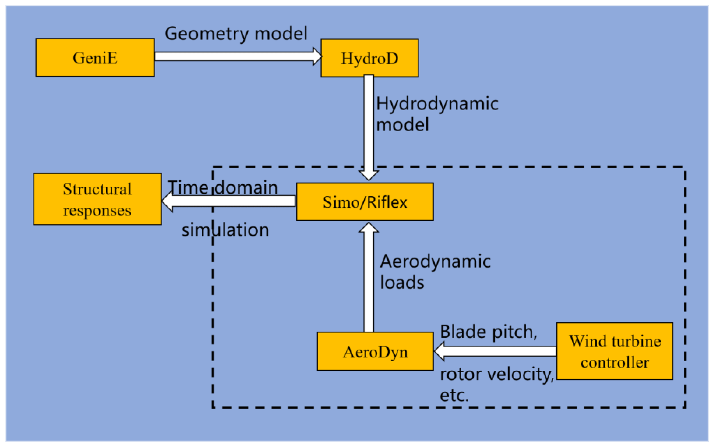
2. Methodology Description
2.1. Aerodynamics
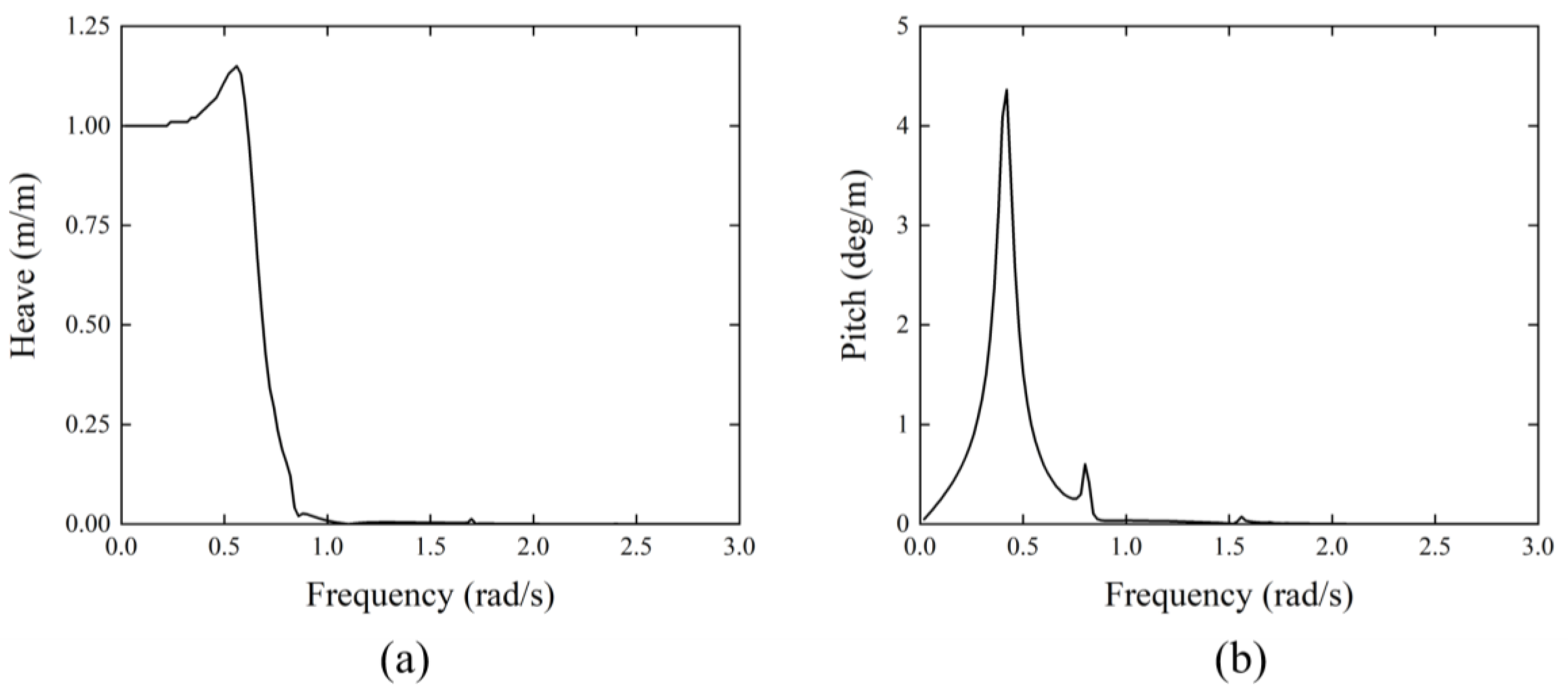
2.2. Hydrodynamics
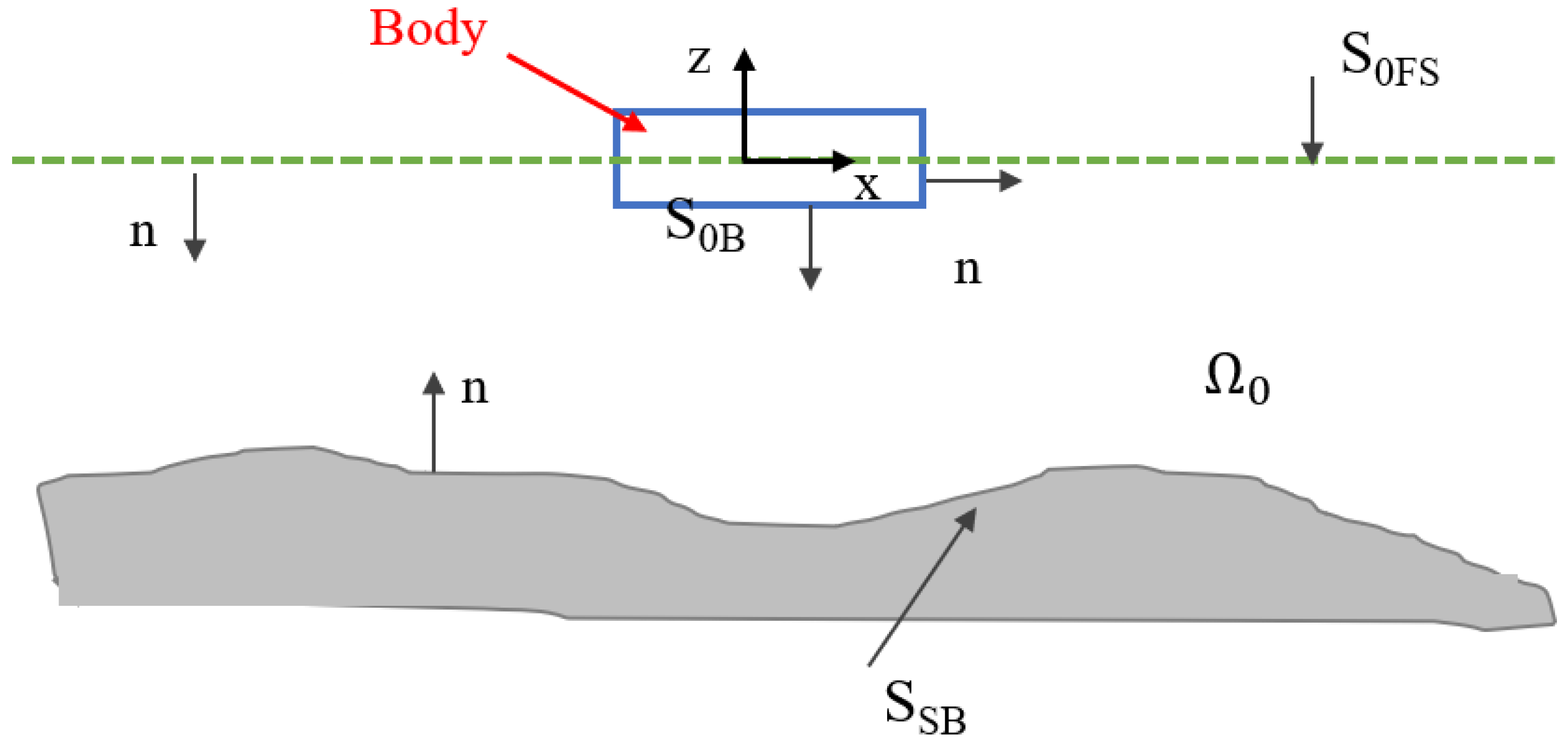
2.2.1. Governing Equations
2.2.2. Equations of Motion
3. Numerical Model
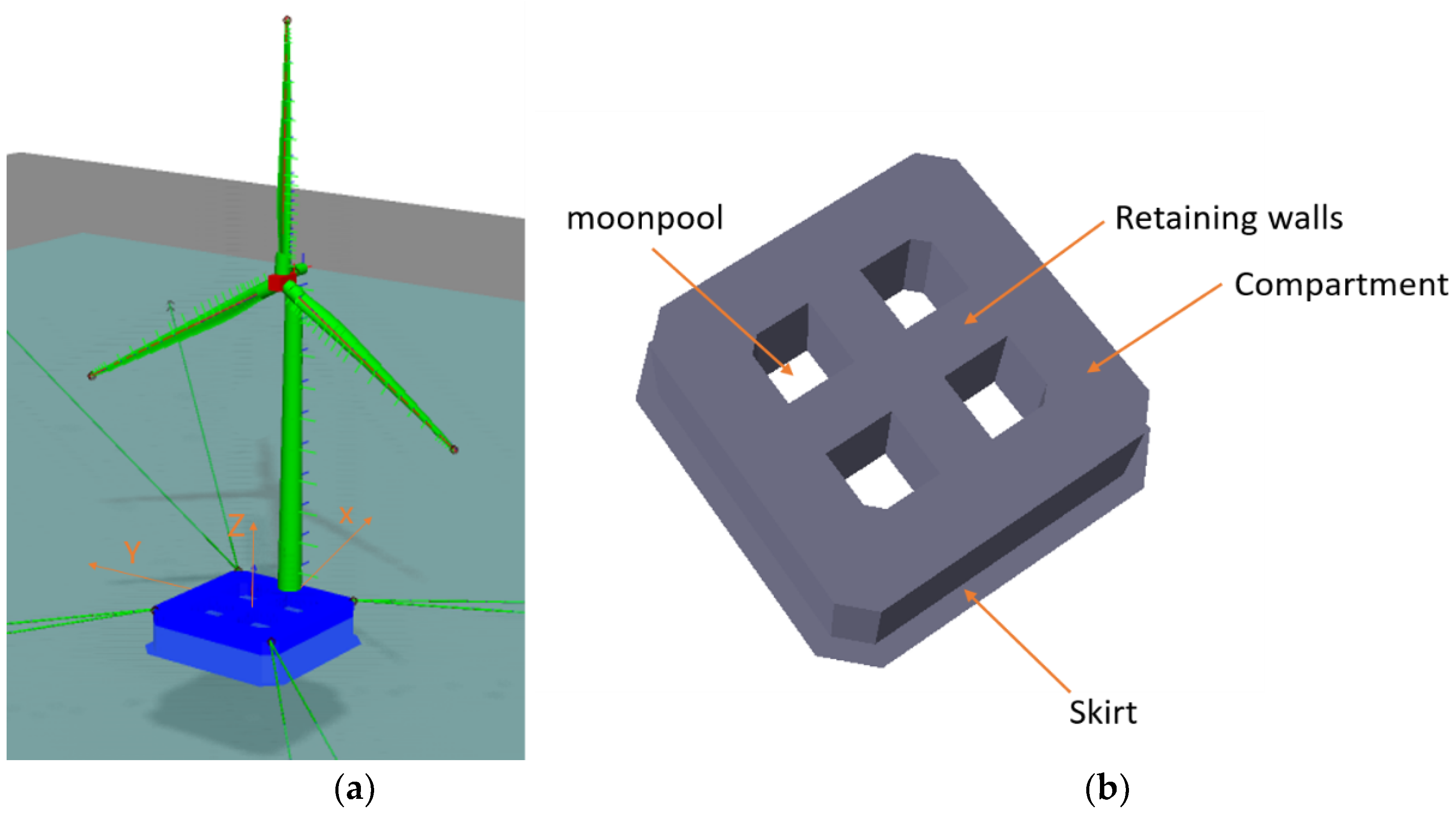
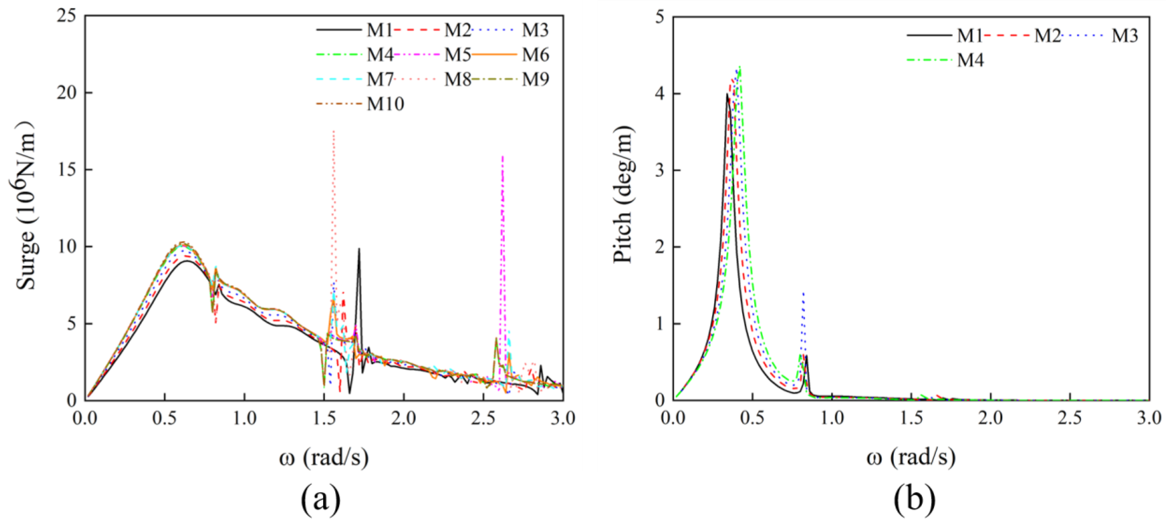
3.1. Design of the Substructure for the 10 MW Wind Turbine
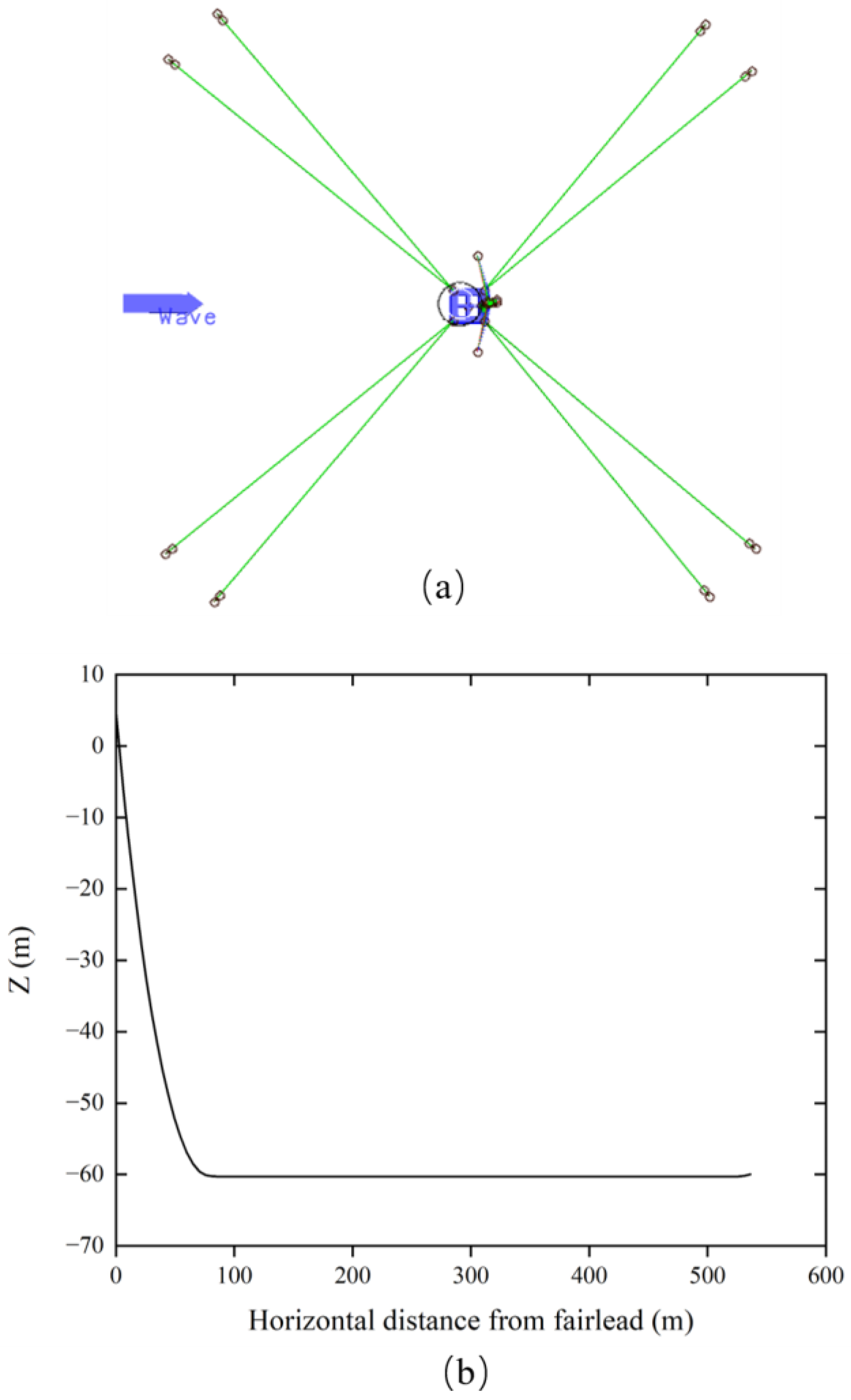
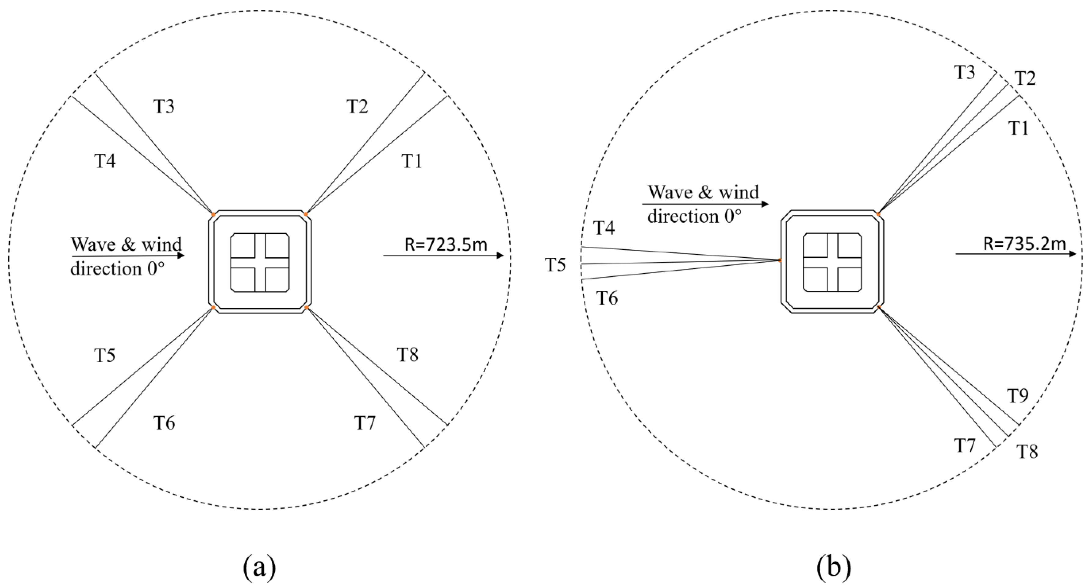
3.2. Mooring System
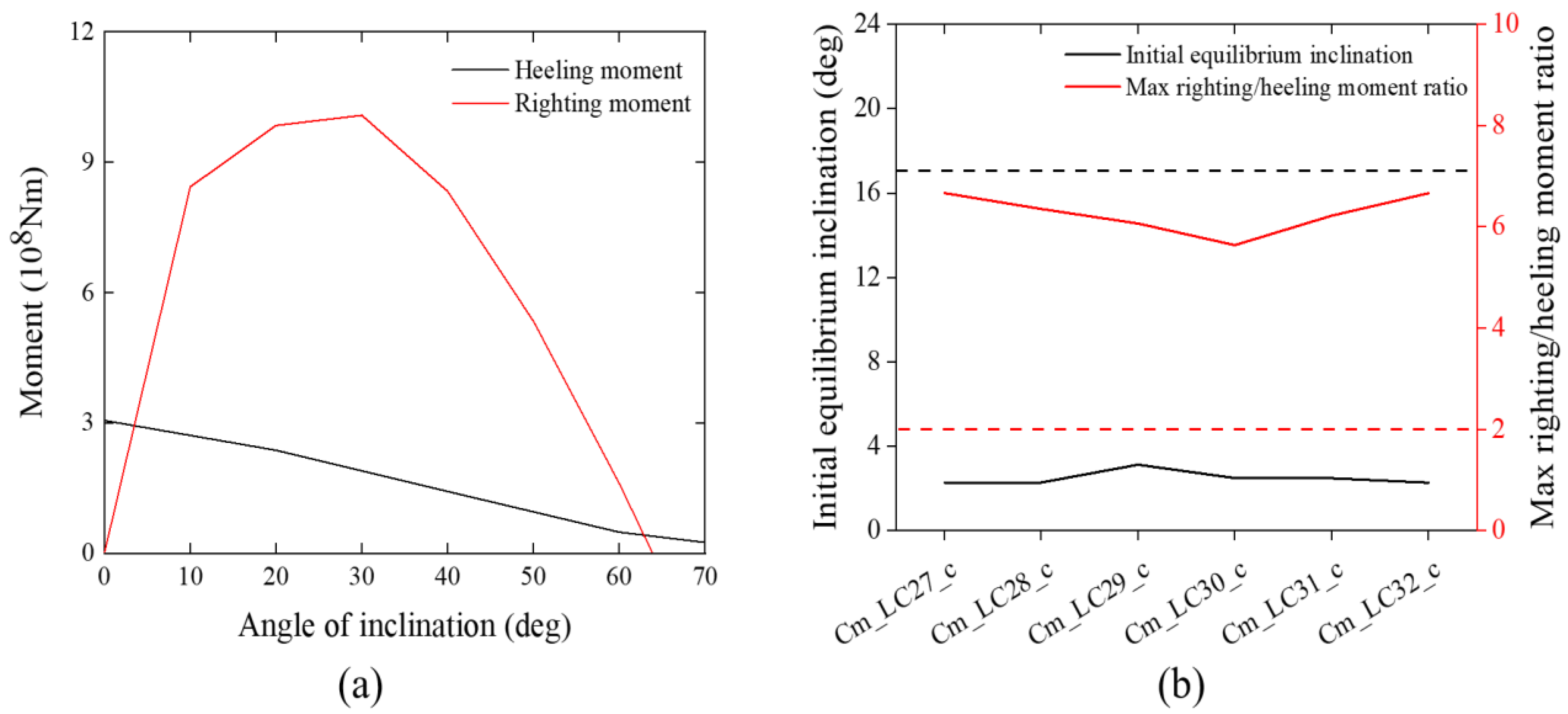
4. Stability Analysis
- (1)
- The area under the righting moment curve being equal to or greater than 140% of the area under the wind heeling moment curve for the inclination angles until the second intercept.
- (2)
- Over the entire range of angles from upright to the second intercept, the righting moment curve shall be positive.
- (1)
- The ratio of the max righting moment and heeling moment should be greater than 2.
- (2)
- The initial equilibrium inclination for the damaged condition should be less than 17°
5. Coupled Time Domain Analysis
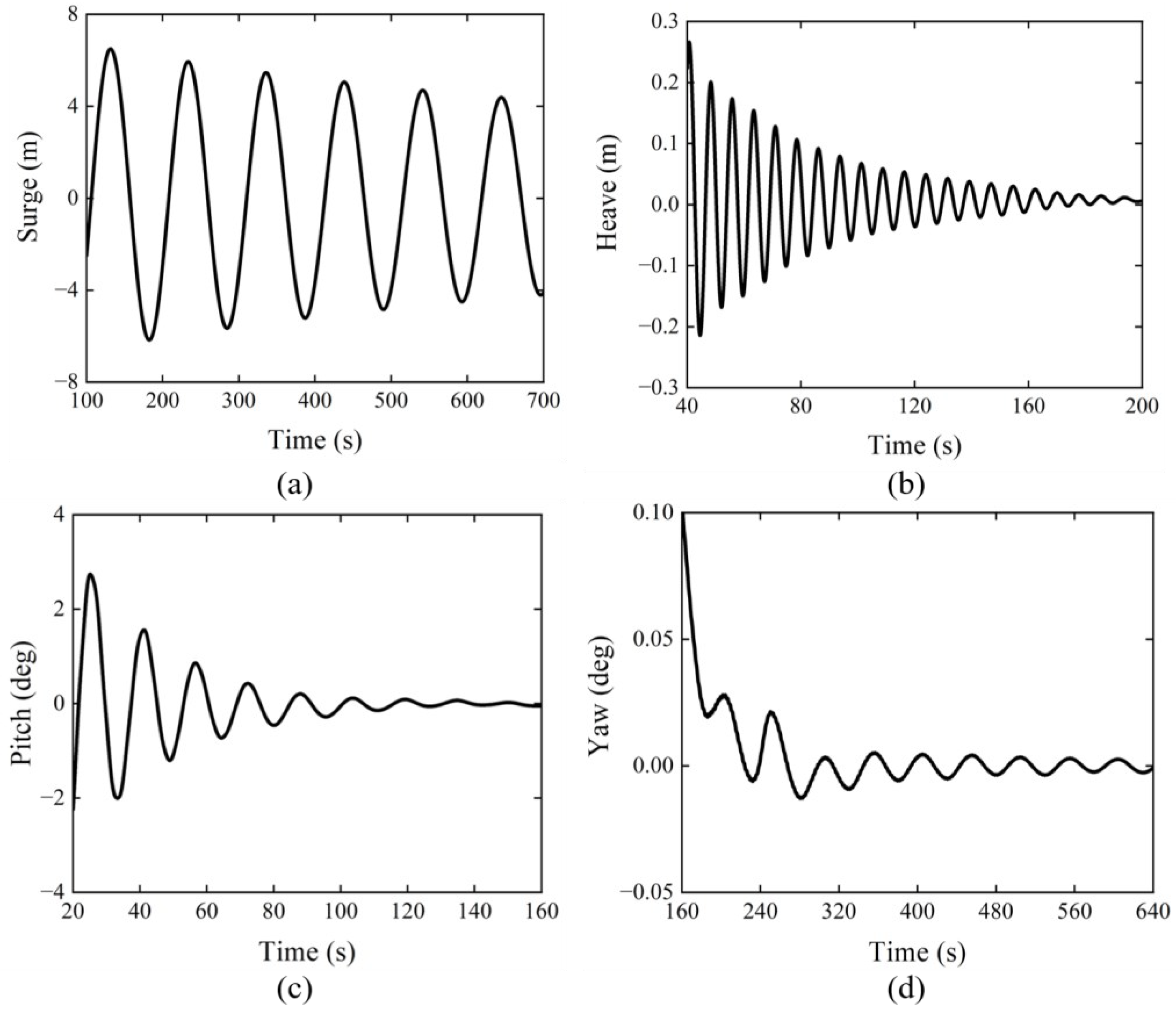
5.1. Free Decay Tests
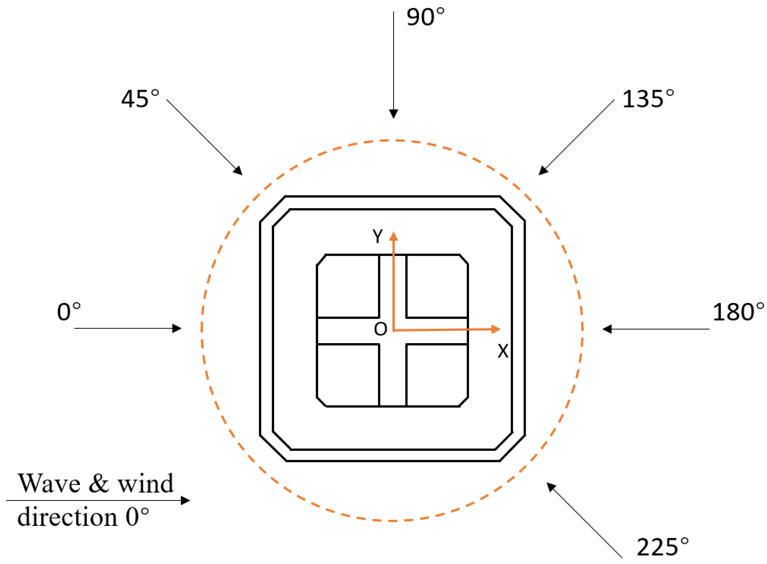
5.2. Environmental Conditions
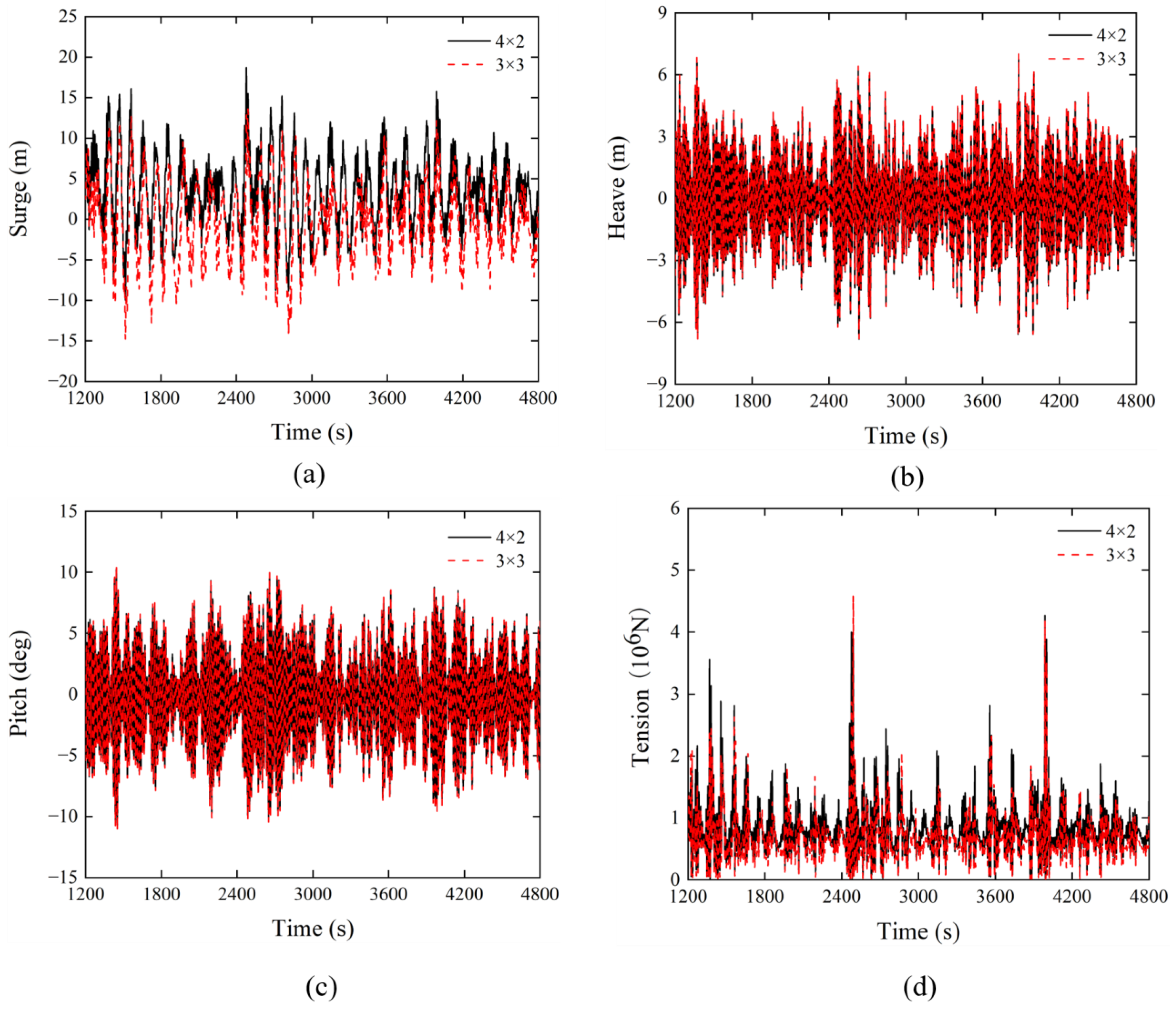
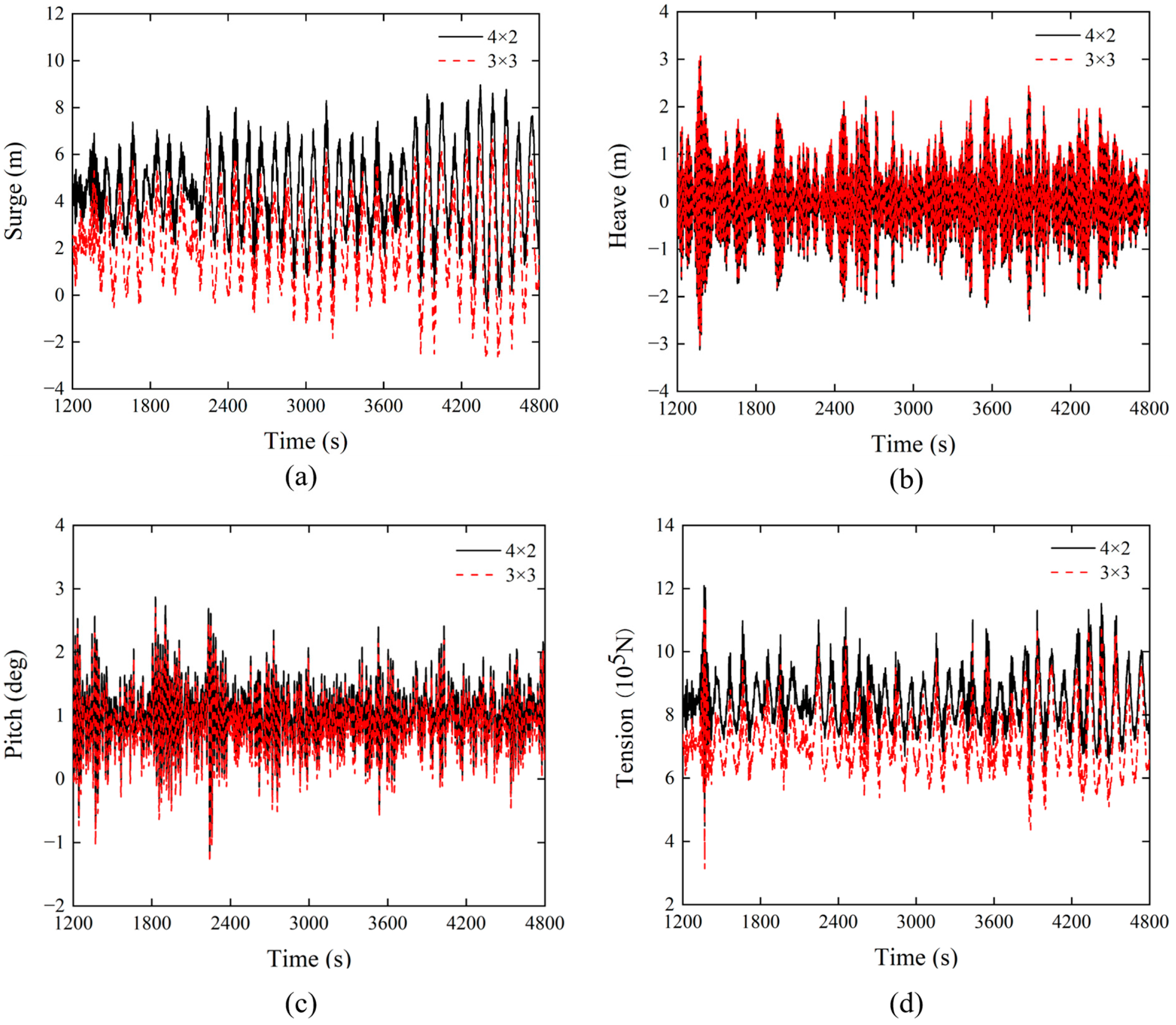
5.3. Comparative Analysis of Different Mooring System Designs
5.4. Influences of Wind and Wave Loads on the Barge-Type FOWT Dynamics
6. Conclusions and Future Work
- (1)
- The newly designed barge FOWT system is proven to have reasonably good stability. Its six DoF natural periods and intact and damage stability meet the relevant DNV recommendations.
- (2)
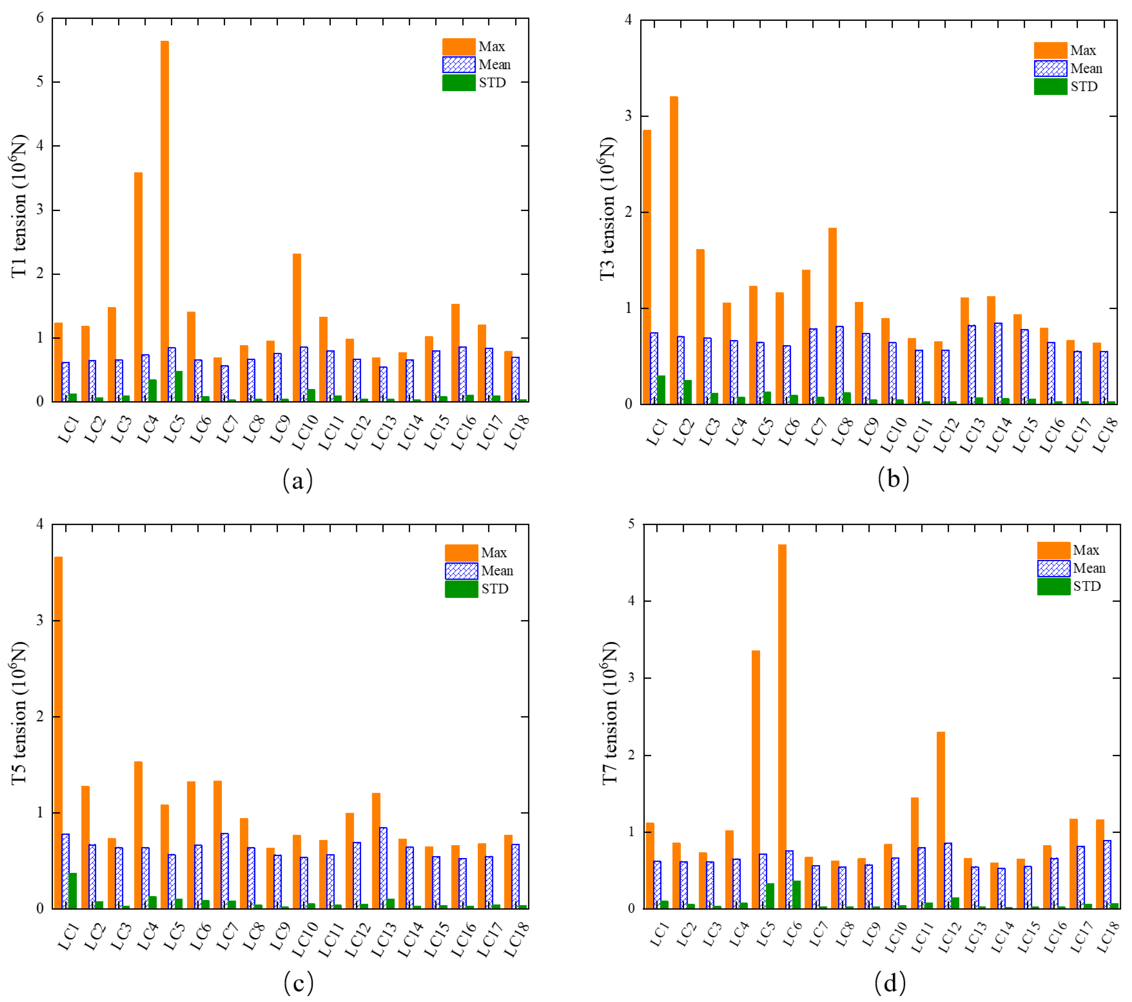
- The difference in the dynamic response of the barge FOWT with the 4 × 2 and the 3 × 3 mooring system design is not very significant. Therefore, the 4 × 2 mooring system design is chosen from an economic point of view. The maximum mooring line tension is 5634.3 kN, which is sufficiently smaller than the breaking load of the mooring lines.
- (3)
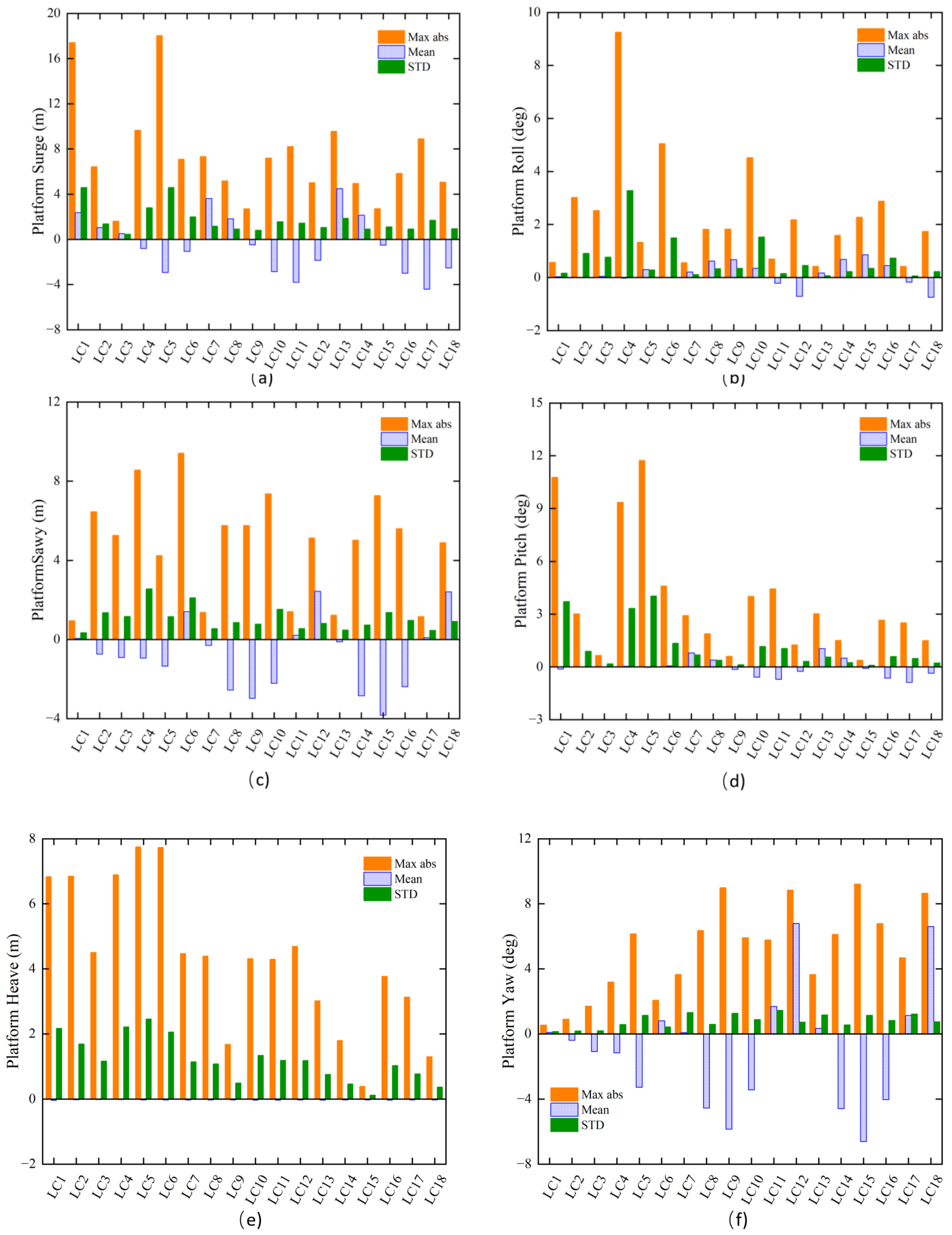
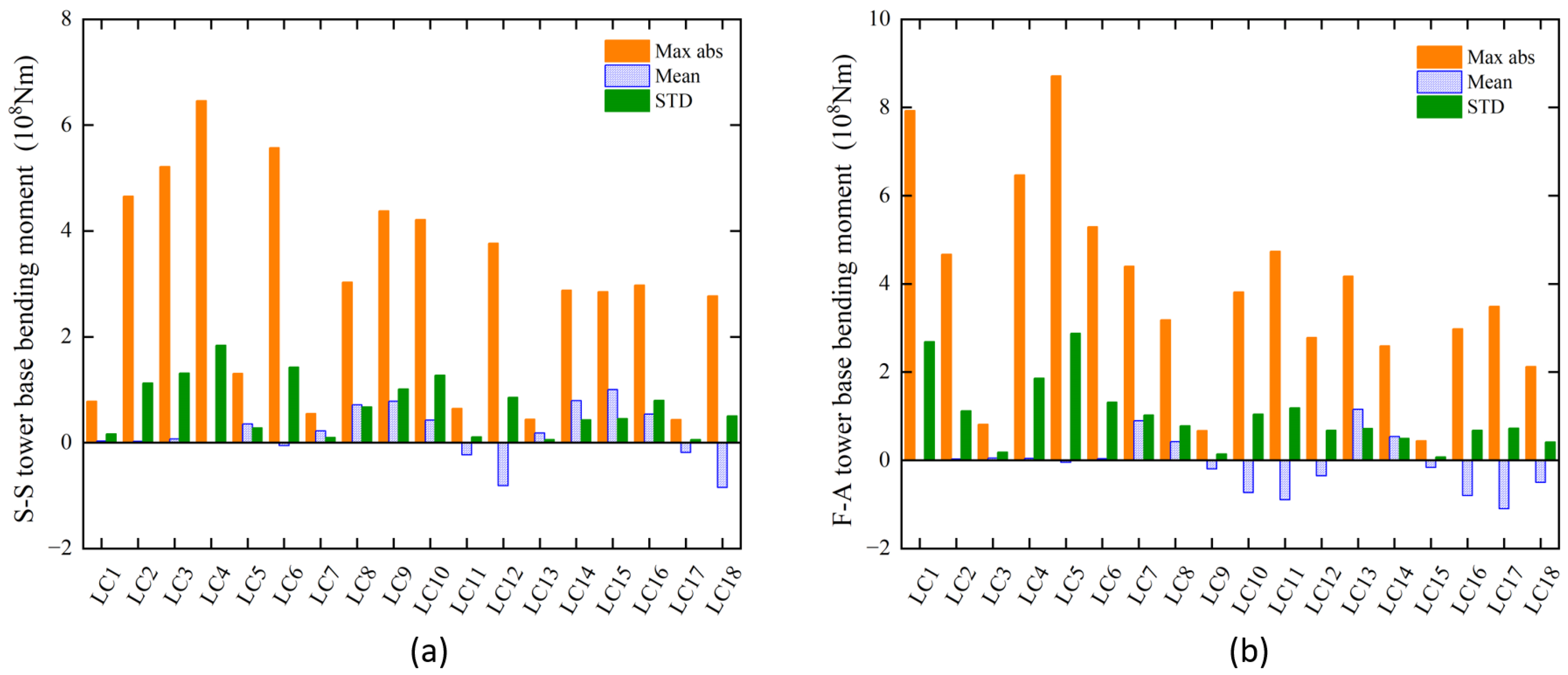
- The platform motions under the considered 18 load cases are also studied. The motion responses of the integrated barge-type FOWT system are within reasonable ranges. Particularly, the largest pitch and roll responses are demonstrated to be acceptable based on the limited scope of simulations.
- (1)
- Considering more complete environmental conditions (e.g., including current effects);
- (2)
- Checking that the critical structural responses against the ultimate strengths of relevant materials;
- (3)
- Ensuring that the platform meets the design life through fatigue assessment;
- (4)
- Checking the proposed mooring system can well function with the failure of an arbitrary mooring line;
- (5)
- Ensuring the design of turbine and blades meeting the relevant standards.
Author Contributions
Funding
Institutional Review Board Statement
Informed Consent Statement
Data Availability Statement
Conflicts of Interest
References
- Shi, W.; Zhang, L.; Karimirad, M.; Michailides, C.; Jiang, Z.; Li, X. Combined effects of aerodynamic and second-order hydrodynamic loads for three semisubmersible floating wind turbines in different water depths. Appl. Ocean Res. 2023, 130, 103416. [Google Scholar] [CrossRef]
- U.S. Department of Energy DOE. 20% Wind Energy by 2030: Increasing Wind Energy’s Contribution to U.S. Electricity Supply; Executive Summary; U.S. Department of Energy: United States, 2008. Available online: https://www.energy.gov/eere/wind/articles/20-wind-energy-2030-increasing-wind-energys-contribution-us-electricity-supply-0 (accessed on 17 March 2022).
- Barthelmie, R.J.; Pryor, S.C. Climate Change Mitigation Potential of Wind Energy. Climate 2021, 9, 136. [Google Scholar] [CrossRef]
- Shi, W.; Zeng, X.; Feng, X.; Shao, Y.; Li, X. Numerical study of higher-harmonic wave loads and runup on monopiles with and without ice-breaking cones based on a phase-inversion method. Ocean Eng. 2023, 267, 113221. [Google Scholar] [CrossRef]
- Chen, J.; Pei, A. A Review of the Key Technologies for Floating Offshore Wind Turbines. South Energy Constr. 2020, 7, 8–20. (In Chinese) [Google Scholar]
- Zhang, L.; Shi, W.; Zeng, Y.; Michailides, C.; Zheng, S.; Li, Y. Experimental investigation on the hydrodynamic effects of heave plates used in floating offshore wind turbines. Ocean Eng. 2023, 267, 113103. [Google Scholar] [CrossRef]
- Jonkman, J.M. Dynamics Modeling and Loads Analysis of an Offshore Floating Wind Turbine; Technical Report NREL/TP-500-41958; University of Colorado: Boulder, CO, USA, 2007. [Google Scholar]
- Wayman, E.N.; Sclavounos, P.D.; Butterfield, S.; Jonkman, J.; Musial, W. Coupled Dynamic Modeling of Floating Wind Turbine Systems. In Proceedings of the 2006 Offshore Technology Conference, Houston, TX, USA, 1–4 May 2006. [Google Scholar]
- Jonkman, J.M.; Buhl, M.L. Loads Analysis of a Floating Offshore Wind Turbine Using Fully Coupled Simulation. In Proceedings of the Wind Power 2007 Conference and Exhibition, Los Angeles, CA, USA, 3–6 June 2007. [Google Scholar]
- Jonkman, J.; Matha, D. A Quantitative Comparison of the Responses of Three Floating Platforms. In Proceedings of the European Offshore Wind 2009 Conference and Exhibition, Stockholm, Sweden, 14–16 September 2009. [Google Scholar]
- Zhao, Z.; Shi, W.; Wang, W.; Qi, S.; Li, X. Dynamic Analysis of a Novel Semi-submersible Platform for a 10 MW Wind Turbine in Intermediate Water Depth. Ocean Eng. 2021, 237, 109688. [Google Scholar] [CrossRef]
- Ren, Y.; Venugopal, V.; Shi, W. Dynamic Analysis of a Multi-column TLP Floating Offshore Wind Turbine with Tendon Failure Scenario. Ocean Eng. 2022, 245, 110472. [Google Scholar] [CrossRef]
- Mayilvahanan, A.; Selvam, P.R. Time Domain Response Analysis of Barge Floater Supporting an Offshore Wind Turbine. Int. J. Ocean Clim. Syst. 2011, 2, 303–314. [Google Scholar] [CrossRef] [Green Version]
- Bossler, A. Floating Offshore Wind Foundations: Industry Consortia and Projects in the United States. Europe and Japan, Maine International Consulting LLC. 2013. Available online: https://1library.net/document/qm6v837y-floating-offshore-foundations-industry-consortia-projects-pro (accessed on 19 March 2022).
- Borisade, F.; Choisnet, T.; Cheng, P.W. Design Study and Full Scale MBS-CFD Simulation of the IDEOL Floating Offshore Wind Turbine Foundation. J. Phys. 2016, 753, 92002. [Google Scholar] [CrossRef] [Green Version]
- Guignier, L.; Courbois, A.; Mariani, R.; Choisnet, T. Multibody Modelling of Floating Offshore Wind Turbine Foundation for Global Loads Analysis. In Proceedings of the Twenty-Sixth (2016) International Ocean and Polar Engineering Conference, Rhodes, Greece, 26 June–1 July 2016. [Google Scholar]
- Choisnet, T.; Geschier, B.; Vetrano, G. Initial Comparison of Concrete and Steel Hulls in the Case of IDEOL’S Square Ring Floating Substructure, WWEC 2016. Available online: https://www.researchgate.net/publication/335727818 (accessed on 24 March 2022).
- Kosasih, K.M.A.; Niizato, H.; Okubo, S.; Mitani, S.; Suzuki, H. Wave Tank Experiment and Coupled Simulation Analysis of Barge-Type Offshore Wind Turbine. In Proceedings of the 29th International Society of Offshore and Polar Engineering Conference (ISOPE-2019), Hawaii, HI, USA, 16–21 June 2019. [Google Scholar]
- Vijay, K.G.; Karmakar, D.; Uzunoglu, E.; Soares, C.G. Performance of Barge-Type Floaters for Floating Wind Turbine. In Proceedings of the 2nd International Conference of Renewable Energies Offshore (Renew 2016), Lisbon, Portugal, 24–26 October 2016. [Google Scholar]
- Ikoma, T.; Nakamura, M.; Moritsu, S.; Aida, Y.; Masuda, K.E.H. Effects of Four Moon Pools on a Floating System Installed with Twin-VAWTs. In Proceedings of the ASME 2019 2nd International Offshore Wind Technical Conference, St. Julian’s, Malta, 3–6 November 2019. [Google Scholar]
- Ikoma, T.; Tan, L.; Moritsu, S.; Aida, Y.; Masuda, K. Motion Characteristics of a Barge-type Floating Vertical-axis Wind Turbine with Moonpools. Ocean Eng. 2021, 230, 109006. [Google Scholar] [CrossRef]
- Sintef Ocean. SIMA Documentation. Available online: https://sima.sintef.no/doc/4.4.0/sima/index.html (accessed on 21 May 2022).
- Manwell, J.F.; McCowan, J.G.; Rogers, A.L. Wind Energy Explained: Theory, Design and Application; John Wiley & Sons: New York, NY, USA, 2002. [Google Scholar]
- Zeng, Y.; Shi, W.; Ren, Z.; Li, X. Turbulence Model Effects on the Hydrodynamic Response of an Oscillating Water Column (OWC) with Use of a Computational Fluid Dynamics Model. Energy 2022, 261, 124926. [Google Scholar] [CrossRef]
- Greco, M. Lecture Notes to TMR 4215: Sea Loads; Department of Marine Technology, Norwegian University of Science and Technology: Trondheim, Norway, 2012. [Google Scholar]
- Craig, R.R.; Kurdila, A.J. Fundamentals of Structural Dynamics, 2nd ed.; John Wiley: Hoboken, NJ, USA, 2006; pp. 13–78. [Google Scholar]
- Naess, A.; Moan, T. Stochastic Dynamics of Marine Structures; Cambridge University Press: Cambridge, UK, 2012. [Google Scholar]
- Bak, C.; Zahle, F.; Bitsche, R.; Kim, T.; Yde, A.; Henriksen, L.C.; Natarajan, A.; Hansen, M.H. Description of the DTU 10 MW Reference Wind Turbine; DTU Wind Energy Report-I-0092; Technical University of Denmark: Roskilde, Demark, 2013. [Google Scholar]
- Wang, Q. Design and Dynamic Analysis of a Steel Pontoon-Type Semi-Submersible Floater Supporting the DTU 10MW Reference Turbine; Norwegian University of Science and Technology: Trondheim, Norway, 2014. [Google Scholar]
- Musial, W.; Butterfield, S.; Ram, B. Energy from Offshore Wind: Preprint. Available online: https://www.nrel.gov/docs/fy06osti/39450.pdf (accessed on 2 February 2023).
- DNV. SESAM User Manual, HydroD V6.1.02. Wave Load & Stability Analysis of Fixed and Floating Structures; DNV: Høvik, Norway, 2022. [Google Scholar]
- DNV. DNVGL-RP-0286 Coupled Analysis of Floating Wind Turbines; DNV: Høvik, Norway, 2019. [Google Scholar]
- DNV. DNVGL-OS-E301 Position Mooring; DNV: Høvik, Norway, 2015. [Google Scholar]
- DNV. Wadam User Manual, Wadam V10.1.03. Wave Analysis by Diffraction and Morison Theory; DNV: Høvik, Norway, 2022. [Google Scholar]
- DNV. DNVGL-OS-C301 Stability and Watertight Integrity; DNV: Høvik, Norway, 2020. [Google Scholar]
- Ormberg, H.; Bachynski, E.E. Global analysis of floating wind turbines: Code development, model sensitivity and benchmark study. In Proceedings of the 22th International Offshore and Polar Engineering Conference, Rhodes, Greece, 17–23 June 2012. [Google Scholar]
- Bachynski, E.E. Design and Dynamic Analysis of Tension Leg Platform Wind Turbines. Ph.D. Thesis, Norwegian University of Science and Technology, Trondheim, Norway, 2014. [Google Scholar]
- Liu, Z. Comparative Hydrodynamic Performance Analysis of Three Typical Kinds of Semi-submersible Floating Foundation of Offshore Wind Turbines. Master’s Thesis, South China University of Technology, Guangzhou, China, 2020. [Google Scholar]
- IEC. 61400-3; Wind Turbines-Part 3: Design Requirements for Offshore Wind Turbines. International Electrotechnical Commission: Geneva, Switzerland, 2009.
- IEC. 61400-1; Wind Turbines-Part 1: Design Requirements for Offshore Wind Turbines. International Electrotechnical Commission: Geneva, Switzerland, 2005.
- Jonkman, J.; Buhl, J.M.L. TurbSim User’s Guide; NREL/TP-500-39797. 2006. Available online: https://www.nrel.gov/docs/fy06osti/39797.pdf (accessed on 10 July 2022).
- Xu, K.; Larsen, K.; Shao, Y.; Zhang, M.; Gao, Z.; Moan, T. Design and Comparative Analysis of Alternative Mooring Systems for Floating Wind Turbines in Shallow Water with Emphasis on Ultimate Limit State Design. Ocean Eng. 2021, 219, 108377. [Google Scholar] [CrossRef]
- Kosasih, K.; Suzuki, H. Demonstration Experiment and Numerical Simulation Analysis of Full-Scale Barge-Type Floating Offshore Wind Turbine. J. Mar. Sci. Eng. 2020, 8, 880. [Google Scholar] [CrossRef]


| Parameter | Values |
|---|---|
| Wind Regime | IEC class 1 A |
| Cut-in wind speed | 4.0 m/s |
| Rated wind speed | 11.4 m/s |
| Cut-out wind speed | 25.0 m/s |
| Rotor diameter | 178.3 m |
| Hub diameter | 5.6 m |
| Hub Height | 119.0 m |
| Minimum rotor speed | 6.0 rpm |
| Maximum rotor speed | 9.6 rpm |
| Maximum tip speed | 90.0 m/s |
| Hub overhang | 7.1 m |
| Shaft tilt angle | 5.0 deg |
| Blade mass | 230,667 kg |
| Nacelle mass | 446,036 kg |
| Tower Mass | 591,758 kg |
| Model ID | Platform Width (Incl. Skirt) | Compartment Width | Skirt Width | Retaining Walls Width |
|---|---|---|---|---|
| M1 | 54 | 10 | 3 | 6 |
| M2 | 56 | 10 | 3 | 6 |
| M3 | 58 | 10 | 3 | 6 |
| M4 | 60 | 10 | 3 | 6 |
| M5 | 60 | 10 | 3 | 7 |
| M6 | 60 | 10 | 3 | 8 |
| M7 | 60 | 11 | 3 | 6 |
| M8 | 60 | 12 | 3 | 6 |
| M9 | 60.6 | 10 | 3.3 | 6 |
| M10 | 61 | 10 | 3.5 | 6 |
| Model ID | Frequency (rad/s) | Periods (s) |
|---|---|---|
| M1 | 0.34 | 18.48 |
| M2 | 0.38 | 16.53 |
| M3 | 0.4 | 15.71 |
| M4 | 0.42 | 14.96 |
| Parameter | Value |
|---|---|
| Barge dimensions (including skirt) | 60 × 60 × 15 m |
| Moonpool dimension | 14 × 14 m |
| Width of retaining walls | 6 m |
| Compartment width | 10 m |
| Skirt width | 3 m |
| Draft | 10 m |
| Barge COG | (−1.349 m, 0 m, −4.595 m) |
| Platform mass (including ballast) | 20,371.539 t |
| Platform steel mass | 4996.68 t |
| Displacement | 21,112.20 m3 |
| Parameter | Valuer |
|---|---|
| Line type | Studless chain |
| Mooring line diameter | 0.153 m |
| Mooring line length | 723.5 m |
| Submerged weight per unit length | 0.447 t/m |
| Radius to anchor from the platform centerline | 735.23 m |
| Minimum breaking load | 2.04 × 10⁴ kN |
| Axial stiffness | 2.1 × 10⁶ kN |
| Pretension at fairlead | 635.23 kN |
| DoF | Natural Periods [s] | |
|---|---|---|
| Simulated | Recommended | |
| Surge/Sway | 103.09 | ~100 |
| Heave | 7.62 | 5–10 |
| Pitch/Roll | 15.67 | 9–16 |
| Yaw | 52.91 | 50–100 |
| Load Case ID | Return Period (Year) | HS (m) | TP (s) | VHub (m/s) | Direction (°) | Turbine Status |
|---|---|---|---|---|---|---|
| LC1 | 50 | 8.96 | 13.50 | 34.16 | 0 | Parked |
| LC2 | 8.45 | 10.40 | 36.78 | 45 | ||
| LC3 | 8.13 | 9.30 | 40.05 | 90 | ||
| LC4 | 8.69 | 16.40 | 35.55 | 135 | ||
| LC5 | 10.16 | 13.80 | 49.01 | 180 | ||
| LC6 | 9.07 | 11.50 | 37.79 | 225 | ||
| LC7 | 5 | 5.10 | 11.10 | 20.77 | 0 | Operating |
| LC8 | 6.21 | 9.80 | 24.92 | 45 | ||
| LC9 | 5.94 | 8.20 | 24.96 | 90 | ||
| LC10 | 5.47 | 13.60 | 23.37 | 135 | ||
| LC11 | 4.99 | 12.20 | 20.15 | 180 | ||
| LC12 | 6.42 | 10.00 | 24.82 | 225 | ||
| LC13 | 2 | 3.50 | 10.80 | 15.22 | 0 | Operating |
| LC14 | 4.22 | 8.70 | 19.17 | 45 | ||
| LC15 | 3.68 | 7.00 | 17.40 | 90 | ||
| LC16 | 4.34 | 12.20 | 18.76 | 135 | ||
| LC17 | 3.81 | 10.40 | 15.64 | 180 | ||
| LC18 | 4.11 | 8.30 | 18.79 | 225 |
| Parameter | 4 × 2 Mooring System | 3 × 3 Mooring System |
|---|---|---|
| Maximum surge (m) | 6.42 | 6.24 |
| Maximum sway (m) | 6.45 | 12.03 |
| Maximum mooring tension (kN) | 3201.59 | 2152.00 |
Disclaimer/Publisher’s Note: The statements, opinions and data contained in all publications are solely those of the individual author(s) and contributor(s) and not of MDPI and/or the editor(s). MDPI and/or the editor(s) disclaim responsibility for any injury to people or property resulting from any ideas, methods, instructions or products referred to in the content. |
© 2023 by the authors. Licensee MDPI, Basel, Switzerland. This article is an open access article distributed under the terms and conditions of the Creative Commons Attribution (CC BY) license (https://creativecommons.org/licenses/by/4.0/).
Share and Cite
Zhou, Y.; Feng, S.; Guo, X.; Tian, F.; Han, X.; Shi, W.; Li, X. Initial Design of a Novel Barge-Type Floating Offshore Wind Turbine in Shallow Water. J. Mar. Sci. Eng. 2023, 11, 464. https://doi.org/10.3390/jmse11030464
Zhou Y, Feng S, Guo X, Tian F, Han X, Shi W, Li X. Initial Design of a Novel Barge-Type Floating Offshore Wind Turbine in Shallow Water. Journal of Marine Science and Engineering. 2023; 11(3):464. https://doi.org/10.3390/jmse11030464
Chicago/Turabian StyleZhou, Yiming, Sensen Feng, Xiaojiang Guo, Feng Tian, Xu Han, Wei Shi, and Xin Li. 2023. "Initial Design of a Novel Barge-Type Floating Offshore Wind Turbine in Shallow Water" Journal of Marine Science and Engineering 11, no. 3: 464. https://doi.org/10.3390/jmse11030464